1
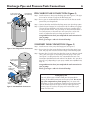
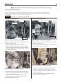
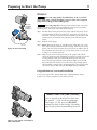
OWNER’S MANUAL
Shallow Well Jet Pumps/
Tank Systems
293 Wright Street, Delavan, WI 53115
“HN” Series
Installation/Operation/Parts
For further operating, installation,
or maintenance assistance:
Call 1-262-728-9181
© 2005, Sta-Rite Industries
S410 (Rev. 7/13/05)
Safety
2
READ AND FOLLOW
SAFETY INSTRUCTIONS!
This is the safety alert symbol. When you see this
symbol on your pump or in this manual, look for
one of the following signal words and be alert to the
potential for personal injury:
warns about hazards that will cause serious
personal injury, death or major property damage if
ignored.
warns about hazards that can cause serious
personal injury, death or major property damage if
ignored.
ELECTRICAL SAFETY
Capacitor voltage may be hazardous. To discharge motor capacitor, hold insulated handle screwdriver
BY THE HANDLE and short capacitor terminals together.
Do not touch metal screwdriver blade or capacitor terminals. If in doubt, consult a qualified electrician.
GENERAL SAFETY
Do not touch an operating motor. Modern
motors are designed to operate at high temperatures. To
avoid burns when servicing pump, allow it to cool for 20
minutes after shut-down before handling.
Do not allow pump or any system component to freeze.
To do so will void warranty.
warns about hazards that will or can cause
minor personal injury or property damage if ignored.
Pump water only with this pump.
The label NOTICE indicates special instructions which
are important but not related to hazards.
Wear safety glasses at all times when working on pumps.
Carefully read and follow all safety instructions in this
manual and on pump.
Keep safety labels in good condition.
Replace missing or damaged safety labels.
WARNING
Wire motor for correct
voltage. See “Electrical”
section of this manual and
motor nameplate.
Ground motor before
connecting to power
supply.
Hazardous voltage.
Can shock, burn, or
cause death.
Ground pump before
connecting to power
supply. Disconnect power
before working on pump,
motor or tank.
Meet National Electrical Code, Canadian
Electrical Code, and local
codes for all wiring.
Follow wiring instructions in this manual
when connecting motor to
power lines.
Periodically inspect pump and system components.
Keep work area clean, uncluttered and properly lighted;
store properly all unused tools and equipment.
Keep visitors at a safe distance from the work areas.
Pump body may explode if used as a
booster pump unless relief valve capable of passing full
pump flow at 75 psi is installed.
WARNING
Hazardous pressure!
Install pressure relief
valve in discharge pipe.
Release all pressure on
system before working on
any component.
Table of Contents
3
Thank you for purchasing a top quality, factory tested pump.
Page
General Safety .....................................................................................................2
Installation ........................................................................................................4,5
Connecting Discharge Piping...............................................................................6
Electrical ...........................................................................................................7,8
Preparing To Start The Pump................................................................................9
Troubleshooting..................................................................................................10
Repair Parts .......................................................................................................11
Warranty ............................................................................................................12
Performance Chart
GPM at depth to water
Model
HP
Disch.
PSI
5 Ft.
10 Ft.
15 ft.
20 Ft.
25 Ft.
Shut Off
Pressure PSI
HNC-L
1/2 HP
30
40
50
15.0
12.5
8.0
13.0
11.4
6.8
11.6
10.1
6.1
8.7
8.2
4.8
6.9
6.8
3.5
70
HND-L
3/4 HP
30
40
50
21.4
20.8
13.5
19.1
18.7
11.6
16.5
15.8
10.1
13.3
13.2
7.4
9.5
9.3
2.4
67
HNE-L*
1 HP
30
40
50
28.5
28.3
21.5
25.0
24.4
18.3
21.4
21.0
10.9
17.4
17.2
3.1
12.6
12.3
1.6
67
* Performance taken with 1-1/2 NPT suction pipe.
Performance Chart for Export Models
GPM at depth to water
Model
HP
Disch.
PSI
5 Ft.
10 Ft.
15 ft.
20 Ft.
25 Ft.
Shut Off
Pressure PSI
HNDX
3/4 HP
30
40
50
15.0
12.5
8.0
13.0
11.4
6.8
11.6
10.1
6.1
8.7
8.2
4.8
6.9
6.8
3.5
70
HNEX
1 HP
30
40
50
21.4
20.8
13.5
19.1
18.7
11.6
16.5
15.8
10.1
13.3
13.2
7.4
9.5
9.3
2.4
67
HNFX
1-1/2 HP
30
40
50
28.5
28.3
21.5
25.0
24.4
18.3
21.4
21.0
10.9
17.4
17.2
3.1
12.6
12.3
1.6
67
Installation
4
To Household
Water System
Pump Priming
Tee and Plug
Suction Pipe
From Well
Priming
Tee and
Plug
Check
Valve
Drive point
below water
level
Drive
Coupling
2346 0396
Drive
Point
Not
to
Scale
Figure 1: Driven Point Installation
To Household
Water System
Pump Priming
Tee and Plug
Suction Pipe
From Well
Check
Valve
Priming
Tee and
Plug
Sanitary
Well Seal
Well
Casing
REPLACING AN OLD PUMP
Hazardous voltage. Disconnect power to pump before working on pump or motor.
Step 1. Drain and remove the old pump. Check the old pipe for scale, lime,
rust, etc., and replace it if necessary.
Step 2. Install the pump in the system. Make sure that all pipe joints in the
suction pipe are air-tight as well as water tight. If the suction pipe
can suck air, the pump will not be able to pull water from the well.
Step 3. Adjust the pump mounting height so that the plumbing connections
do not put a strain on the pump body. Support the pipe so that the
pump body does not take the weight of piping or fittings.
You have just completed the well plumbing for your new shallow
well jet pump. Please go to Page 6 for discharge pipe and tank connections.
WELL POINT (DRIVEN POINT) INSTALLATION
(Figure 1)
Step 1. Drive the well, using “drive couplings” and a “drive cap”. “Drive
fittings” are threaded all the way through and allow the pipe ends to
butt against each other so that the driving force of the maul is carried by the pipe and not by the threads. The ordinary fittings found
in hardware stores are not threaded all the way through the fitting
and can collapse under impact. “Drive fittings” are also smoother
than standard plumbing fittings, making ground penetration easier.
Step 2. Mount the pump as close to the well as possible
Step 3. Use the fewest possible fittings (especially elbows) when connecting
the pipe from the well point to the pump suction port. The suction
pipe should be at least as large as the suction port on the pump
(include a check valve if your pump is not equipped with one – see
Figure 1). Support the pipe so that there are no dips or sags in the
pipe, so it doesn’t strain the pump body, and so that it slopes slightly upward from the well to the pump (high spots can cause air
pockets which can air lock the pump). Seal the suction pipe joints
with teflon tape or a teflon based pipe joint compound. Joints must
be air- and water-tight. If the suction pipe can suck air, the pump
cannot pull water from the well. If one well point does not supply
enough water, consider connecting two or three well points to one
suction pipe.
You have just completed the suction piping for your new shallow
well jet pump. Please go to Page 6 for discharge pipe and tank connections
CASED WELL INSTALLATION, 2" OR LARGER
CASING (Figure 2)
Step 1. Mount the pump as close to the well as possible.
2347 0396
Not
to
Scale
10'
Min.
Foot
Valve
5–10'
Figure 2: Cased Well Installation
Step 2. Assemble the foot valve, strainer, and well pipe (see Figure 2). Make
sure that the foot valve works freely.
Step 3. Lower the pipe into the well until the strainer is five feet above the
bottom of the well. It should also be at least 10 feet below the well’s
water level while the pump is running in order to prevent the pump
from sucking air. Install a sanitary well seal.
Installation
To Household
Water System
5
Pump Priming
Tee and Plug
Suction Pipe
From Well
Check
Valve
Priming
Tee and
Plug
Step 4. Install a priming tee, priming plug, and suction pipe to the pump
(see Figure 2). Connect the pipe from the well to the pump suction
port, using the fewest possible fittings – especially elbows – as fittings increase friction in the pipe (however, include a foot valve –
see Figure 2). The suction pipe should be at least as large as the
suction port on the pump. Use teflon tape or a teflon-based pipe
joint compound on threaded pipe joints. Support the pipe so that
there are no dips or sags in the pipe, so it doesn’t strain the pump
body, and so that it slopes slightly upward from the well to the
pump (high spots can cause air pockets which can air lock the
pump). Seal the suction pipe joints with teflon tape or a teflon
based pipe joint compound. Joints must be air- and water-tight. If
the suction pipe can suck air, the pump cannot pull water from the
well.
You have just completed the suction piping for your new shallow
well jet pump. Please go to Page 6 for discharge pipe and tank
connections.
Not
to
Scale
INSTALLATION FOR SURFACE WATER (Figure 3)
2348 0396
10'
Min.
Foot
Valve
5–10'
Screen
Figure 3: Surface Water Installation
Step 1. The pump should be installed as close to the water as possible,
with the fewest possible fittings (especially elbows) in the suction
pipe. The suction pipe should be at least as large as the suction port
on the pump.
Step 2. Assemble a foot valve and suction pipe (see Figure 3). Make sure
that the foot valve works freely. Use teflon tape or a teflon-based
pipe joint compound on threaded pipe joints. Protect the foot valve
assembly from fish, trash, etc, by installing a screen around it (see
Figure 3).
Step 3. Lower the pipe into the water until the strainer is five feet above the
bottom. It should also be at least 10 feet below the water level in
order to prevent the pump from sucking air.
Step 4. Install a priming tee, priming plug, and suction pipe to the pump
(see Figure 3). Support the pipe so that there are no dips or sags in
the pipe, so it doesn’t strain the pump body, and so that it slopes
slightly upward from the well to the pump (high spots can cause air
pockets which can air lock the pump). Seal the suction pipe joints
with teflon tape or a teflon based pipe joint compound. Joints must
be air- and water-tight. If the suction pipe can suck air, the pump
cannot pull water from the well.
You have just completed the plumbing for your new shallow well
jet pump. Please go to Page 6 for discharge pipe and tank connections.
Discharge Pipe and Pressure Tank Connections
To Household
Water System
Pump Priming
Tee and Plug
From Well
Pressure
Switch
6
PRE-CHARGE TANK CONNECTION (Figure 4)
Step 1. Install two tees in the pump discharge port (see Figure 4). The pipe
size must be at least as large as the discharge port.
Step 2. Run a pipe or reinforced hose from one arm of the first tee to the
port on the pre-charged tank.
Step 3. Connect the other end of the discharge tee to your plumbing system.
Step 4. Check the pre-charge of air in the tank with an ordinary tire gauge.
The pre-charge should be 2 PSI less than the cut-in setting of the
pump’s pressure switch. The pre-charge is measured when there is
no water pressure in the tank. Your new pump has a 30/50 PSI
switch, so adjust the tank pre-charge pressure to 28 PSI.
Check
Valve
Congratulations! You have just completed the tank connection for
your jet pump.
Please go to Pages 7 and 8 for electrical hookup.
STANDARD TANK CONNECTION (Figure 5)
2349 0396
Figure 4: Pre-charged Tank Connections
To Household
Water System
Air Volume
Control
Pump
Priming Tee
and Plug
Air Volume
Control Tube
Step 2. Run a pipe from the pump discharge port to the inlet port of your
tank. The pipe size must be at least as large as the discharge port.
Step 3. Remove the 1/8" NPT pipe plug from the pump Air Volume Control
(AVC) port (see Figure 5). Run tubing from the pump’s AVC port
(see Figure 5) to the port on the AVC mounted on the tank. See
instructions provided with tank and AVC for details. AVC port location will vary, depending on your pump model (see exploded view,
Page 11).
Congratulations! You have just completed the tank connection for
your jet pump.
Please go to Pages 7 and 8 for electrical hookup.
2350 0396
From
Well
Pressure
Switch
Step 1. Install one tee in the pump discharge port (see Figure 5).
Check
Valve
Figure 5: Standard Tank Connections
Sealing Pipe Joints
Use only Teflon tape or Teflon based joint compounds for
making all threaded connections to the pump itself. Do not use
pipe joint compounds on plastic pumps: they can react with
the plastic in pump components. Make sure that all pipe joints
in the suction pipe are air tight as well as water tight. If the
suction pipe can suck air, the pump will not be able to pull
water from the well.
Electrical
7
Disconnect power before working on pump, motor, pressure switch, or wiring.
MOTOR SWITCH SETTINGS
NOTE: 1/2 HP motors are wired for 115 volts only, and have no motor wiring to change.
3/4 HP or 1 HP motor terminal boards (located under the motor end cover) should look like one of those below.
If the motor can operate at either 115 or 230 volts, it is set at the factory to 230 volts. Do not change motor wiring
if line voltage is 230 volts, or if you have a single voltage motor.
Never wire a 115 volt motor to a 230 volt line.
Plug Type Voltage Selector
Dial Type Voltage Selector
Power Supply Connections
Power Connections
Voltage Change Plug
Voltage
Change
Dial
Pressure Switch
ound Wire Connection
Pressure Switch
Ground Wire Connection
Figure 6: Voltage set to 230 volts, Plug Type
Figure 8: Voltage set to 230 volts, Dial Type
Voltage is factory set to 230 volts. To change to 115 volts:
1. Make sure power is off.
2. Pull the voltage change plug off of the tabs.
3. Move the voltage change plug to the 115 volt position. The plug will now cover 2 metal tabs and the
arrow on the plug will line up with the 115V arrow on
the label (see Figure 7).
Voltage is factory set to 230 volts. To change to 115 volts:
1. Make sure power is off.
2. Turn the dial counter-clockwise until 115 shows in the
dial window as shown in Figure 9.
Figure 9: Voltage set to 115 volts, Dial Type
Figure 7: Voltage set to 115 volts, Plug Type
4. Attach the incoming power leads to the two outer
screws on the pressure switch as shown in Figure 6.
5. Attach the ground wire to one of the grounding
connections, shown in Figure 6.
6. If there are other wires, they should be capped.
7. Reinstall the Motor end cover.
3. Attach the incoming power leads to the two outer
screws on the pressure switch as shown in Figure 8.
4. Attach the ground wire to the grounding connections
as shown in Figure 8.
5. If there are other wires, they should be capped.
6. Reinstall the Motor end cover.
Electrical
8
Connection Procedure:
Hazardous voltage. Can shock, burn, or
kill. Connect ground wire before connecting power supply wires. Use the wire size (including the ground wire)
specified in the wiring chart. If possible, connect the
pump to a separate branch circuit with no other appliances on it.
Step 1. Connect the ground wire first as shown in Figure
6. The ground wire must be a solid copper wire
at least as large as the power supply wires.
Step 2. There must be a solid metal connection between
the pressure switch and the motor for motor
grounding protection. If the pressure switch is not
connected to the motor, connect the green
ground screw in the switch to the green ground
screw under the motor end cover. Use a solid
copper wire at least as large as the power supply
wires.
Explosion hazard. Do not ground to a gas
supply line.
WIRING CONNECTIONS
Fire hazard. Incorrect voltage can cause a
fire or seriously damage the motor and voids the warranty. The supply voltage must be within ±10% of the motor
nameplate voltage.
Step 3. Connect the ground wire to a grounded lead in a
service panel, to a metal underground water
pipe, to a metal well casing at least ten feet (3M)
long, or to a ground electrode provided by the
power company or the hydro authority.
NOTICE: Dual-voltage motors are factory wired for 230
volts. If necessary, reconnect the motor for 115 volts, as
shown. Do not alter the wiring in single voltage motors.
Install, ground, wire, and maintain your pump in compliance with the United States National Electrical Code
(NEC) or the Canadian Electrical Code (CEC), as applicable, and with all local codes and ordinances that apply.
Consult your local building inspector for code information.
Step 4. Connect the power supply wires to the pressure
switch as shown in Figure 6.
You have just completed the wiring for your
pump.
Please go to Page 9 for startup preparations.
Wiring Chart – Recommended Wire and Fuse Sizes
DISTANCE IN FEET(METERS) FROM MOTOR TO SUPPLY
Model
Volts
Max. Load
Amp
HNC-L
115/230
12.2/6.1
Branch Fuse
Rating Amp
20/15
0 - 100
(0 - 30)
101 - 200
(31 - 61)
201 - 300
(62 - 91)
301 - 400
(92 - 122)
401 - 500
(123 - 152)
6/12 (14/3)
6/12 (14/3)
AWG WIRE SIZE (mm2)
12/14 (3/2)
10/14 (5.5/2)
8/14 (8.4/2)
HND-L
115/230
14.8/7.4
20/15
12/14 (3/2)
8/14 (8.4/2)
6/14 (14/2)
6/12 (14/3)
4/10 (21/5.5)
HNE-L
115/230
19.9/10.0
25/15
10/14 (5.5/2)
8/14 (8.4/2)
6/12 (14/3)
4/10 (21/5.5)
4/10 (21/5.5)
Wiring Chart – Recommended Wire and Fuse Sizes - HNX Series Pumps
DISTANCE IN FEET(METERS) FROM MOTOR TO SUPPLY
Model
Volts
Max. Load
Amp
Branch Fuse
Rating Amp
0 - 100
(0 - 30)
101 - 200
(31 - 61)
201 - 300
(62 - 91)
301 - 400
(92 - 122)
401 - 500
(123 - 152)
AWG WIRE SIZE (mm2)
HNDX
115/230
12.2/6.1
20/15
12/14 (3/2)
10/14 (5.5/2)
8/14 (8.4/2)
6/12 (14/3)
6/12 (14/3)
HNEX
115/230
14.8/7.4
20/15
12/14 (3/2)
8/14 (8.4/2)
6/14 (14/2)
6/12 (14/3)
4/10 (21/5.5)
HNFX
115/230
19.9/10.0
25/15
10/14 (5.5/2)
8/14 (8.4/2)
6/12 (14/3)
4/10 (21/5.5)
4/10 (21/5.5)
Preparing to Start the Pump
9
PRIMING
Never run pump against closed discharge. To do so can boil
water inside pump, causing hazardous pressure in unit, risk of explosion
and possibly scalding persons handling pump.
Fill pump
and piping
through
priming tee.
Never run pump dry. Running pump without water may cause
pump to overheat, damaging seal and possibly causing burns to persons
handling pump. Fill pump with water before starting.
Step 1. Remove the priming plug from the pump and fill the pump, fill all
piping between the pump and the well, and make sure that all piping in the well is full. If you have also installed a priming tee in the
suction piping, remove the plug from the tee and fill the suction
piping.
Step 2. Replace all fill plugs.
2351 0396
Figure 10: Prime the Pump
Step 3. Power on! Start the pump. If you don’t have water after 2 or 3 minutes, stop the pump and remove the fill plugs. Refill the pump and
piping. You may have to repeat this several times in order to get all
the trapped air out of the piping. A pump lifting water 25’ may take
as long as 15 minutes to prime.
Step 4. After the pump has built up pressure in the system and shut off,
check the pressure switch operation by opening a faucet or two and
running enough water out to bleed off pressure until the pump
starts. The pump should start when pressure drops to 30 PSI and
stop when pressure reaches 50 PSI. Run the pump through one or
two complete cycles to verify correct operation. This will also help
clean the system of dirt and scale dislodged during installation.
Congratulations on a successful installation.
If you were unsuccessful, please refer to the Troubleshooting section
(Page 10) or call our customer service technical staff.
Nozzle Clean Out (Low Pressure)
Use an icepick or brad awl to clean out
the nozzle – 3/16" maximum diameter
(see Figure 11). Be sure you DO NOT
enlarge the hole in the nozzle. Use teflon
tape on plug when reassembling to seal it.
1465 0497
Figure 11: Use Icepick or Brad Awl to
Clean Out Nozzle
Troubleshooting
SYMPTOM
Motor will not run
Motor runs hot and
overload kicks off
Motor runs but no
water is delivered*
* (Note: Stop pump;
then check prime
before looking for
other causes.
Unscrew priming
plug and see if water
is in priming hole).
Pump does not
deliver water to full
capacity
10
POSSIBLE CAUSE(S)
CORRECTIVE ACTION
Disconnect switch is off
Fuse is blown or circuit breaker tripped
Starting switch is defective
Wires at motor are loose,
disconnected, or wired incorrectly
Be sure switch is on.
Replace fuse or reset circuit breaker.
DISCONNECT POWER; Replace starting switch.
Refer to instructions on wiring (Pages 7 and 8). DISCONNECT POWER;
check and tighten all wiring.
Pressure switch contacts are dirty
Capacitor voltage may be hazardous. To discharge
capacitor, hold insulated handle screwdriver BY THE HANDLE and
short capacitor terminals together. Do not touch metal screwdriver
blade or capacitor terminals. If in doubt, consult a qualified electrician.
DISCONNECT POWER and file contacts with emery board or nail file.
Motor is wired incorrectly
Voltage is too low
Refer to instructions on wiring.
Check with power company. Install heavier wiring if wire size is too small
(See Electrical / Wiring Chart).
Pump cycles too frequently
See section below on too frequent cycling.
Pump in new installation did
not pick up prime through:
1. Improper priming
2. Air leaks
In new installation:
3. Leaking foot valve or check valve
Pump has lost prime through:
1. Air leaks
2. Water level below suction pipe inlet
Foot valve or strainer is plugged
Ejector or impeller is plugged
Check valve or foot valve is stuck shut
Pipes are frozen
Foot valve and/or strainer are
buried in sand or mud
Water level is too low for shallow well
setup to deliver water
1. Re-prime according to instructions.
2. Check all connections on suction line, AVC, and ejector with
soapy water or shaving cream.
3. Replace foot valve or check valve.
In installation already in use:
1. Check all connections on suction line and shaft seal.
2. Lower suction line into water and re-prime. If receding water level
in well exceeds 25’ (7.6M), a deep well pump is needed.
Clean foot valve or strainer.
Clean ejector or impeller.
Replace check valve or foot valve.
Thaw pipes. Bury pipes below frost line. Heat pit or pump house.
Raise foot valve and/or strainer above bottom of water source.
Clean foot valve and strainer.
A deep well jet package may be needed (over 25 ft. to water)
to deliver water.
Water level in well is lower than
estimated
Steel piping (if used) is corroded or
limed, causing excess friction
Piping is too small in size
Packed well point
A deep well jet will be needed if your well is more than 25’ (7.6M)
depth to water.
Replace with plastic pipe where possible, otherwise with new steel pipe.
Pump delivers water but
does not shut off or
pump cycles too
frequently
Pressure switch is out of adjustment or
contacts are welded together
Faucets have been left open
Venturi, nozzle or impeller is clogged
Standard pressure tank is waterlogged
and has no air cushion
Pipes leak
Foot valves leak
Air charge too low in pre-charged tank
DISCONNECT POWER; adjust or replace pressure switch.
Air spurts from faucets
Pump is picking up prime
Leak in suction side of pump
Well is gaseous
Intermittent over-pumping of well.
(Water drawn down below foot valve.)
Use larger piping.
Backflush well point or sink new point.
Close faucets.
Clean venturi, nozzle or impeller.
Drain tank to air volume control port. Check AVC for defects. Check
all connections for air leaks.
Check connections.
Replace foot valve.
DISCONNECT POWER and open faucets until all pressure is relieved.
Using tire pressure gauge, check air pressure in tank at valve stem
located on the tank. If less than pressure switch cut-in setting (30-50
PSI), pump air into tank from outside source until air pressure is 2 PSI
less than cut-in setting of switch. Check air valve for leaks (use soapy
solution) and replace core if necessary.
When pump has picked up prime, it should pump solid water with no air.
Suction pipe is sucking air. Check joints for leaks with soapy water.
Consult factory about installing a sleeve in the well
Lower foot valve if possible, otherwise restrict pump discharge
Repair Parts
11
1
2
19
20
3
4
18
5
6
7
8
9
11
17
10
16
12
15
11A
14
Nozzle
Cleanout
Port
11B
13
2763 0197
12
REPAIR PARTS LIST
Key
No.
1
2
2
3
4
5
6
7
8
9
10
11
11A
11B
12
13
14
15
16
17
18
19
20
•
•
•
Part Description
Motor
Capscrew 3/8-16x1-1/4" Lg. Hex Hd.
Capscrew 3/8-16x1-1/2" Lg. Hex Hd.
Water Slinger
Seal Plate Assembly
Gasket, Seal Plate
Shaft Seal
Impeller
Volute Diffuser
Gasket, Diffuser
Quick Connect, 1/4" NPT
Pump Body Assembly*
Venturi
Nozzle
Pipe Plug, 1/4" NPT Hex Hd.
Capscrew 3/8-16x1-1/2" Lg. Hex Hd.
Base
Rubber Pad
Tube, 1/4" I.D. (length varies)
Quick Connect Elbow, 1/4" NPT
Pressure Switch
Locknut, 1/2"
Connector
Diffuser Screw, #8-32x3/4"
Diffuser Washer, #8 Ext. Tooth
Pulsation Plug
Qty.
1
4
2
1
1
1
1
1
1
1
1
1
1
1
HNC-L
1/2 HP
J218-590PKG
U30-75ZP
–
17351-0009
N3-9
N20-35
U109-6A
J105-42P
L1-25P
N20-34
U11-217P
N176-43B
N32P-75
N34P-21 (#47)
( ) U78-941ZPV(3)
2 –
1 J4-9
1 C35-5
1 U37-676P
1 U11-218P
1 U217-1216
1 U36-112ZPP
1 L43-5C
3 –
3 –
1 –
HNDX
3/4 HP
HND-L
3/4 HP
HNEX
1 HP
HNE-L
1 HP
HNFX
1-1/2 HP
J218-590PKG
U30-75ZP
–
17351-0009
N3-9
N20-35
U109-6A
J105-42P
L1-25P
N20-34
U11-217P
N176-43B
N32P-75
N34P-21 (#47)
U78-941ZPV(3)
–
J4-9
C35-5
U37-676P
U11-218P
U217-1216
U36-112ZPP
L43-5C
–
–
–
J218-596PKG
–
U30-76ZP
17351-0009
L3-10
C20-21
U109-6A
J105-8PAN
L1-23P
N20-34
U11-217P
N176-44
N32P-64
J34P-44 (#54)
U78-941ZPV(4)
U30-76ZP
J4-9C
C35-5
U37-672P
U11-218P
U217-1216
U36-112ZPP
L43-5C
U30-489SS
U43-21SS
–
J218-596PKG
–
U30-76ZP
17351-0009
L3-10
C20-21
U109-6A
J105-8PAN
L1-23P
N20-34
U11-217P
N176-44
N32P-64
J34P-44 (#54)
U78-941ZPV(4)
U30-76ZP
J4-9C
C35-5
U37-672P
U11-218P
U217-1216
U36-112ZPP
L43-5C
U30-489SS
–
–
J218-601PKG
–
U30-76ZP
17351-0009
L3-10
C20-21
U109-6A
J105-22PA
L1-23P
N20-34
U11-217P
N176-44A
N32P-65
J34P-44 (#54)
U78-941ZPV(4)
U30-76ZP
J4-9C
C35-5
U37-677P
U11-218P
U217-1216
U36-112ZPP
L43-5C
U30-489SS
U43-21SS
U17-1131
J218-601PKG
–
U30-76ZP
17351-0009
L3-10
C20-21
U109-6A
J105-22PA
L1-23P
N20-34
U11-217P
N176-44A
N32P-65
J34P-44 (#54)
U78-941ZPV(4)
U30-76ZP
J4-9C
C35-5
U37-677P
U11-218P
U217-1216
U36-112ZPP
L43-5C
U30-489SS
U43-21SS
U17-1131
• Not illustrated.
* Models HNC-L and HNDX require 3 pipe plugs; other models require 4 pipe plugs.
12
LIMITED WARRANTY
Sta-Rite Industries warrants to the original consumer of the products listed below, that they will be free from
defects in material and workmanship for the Warranty Period from the date of original installation or manufacture
as noted.
Product
Warranty Period
Water Systems Products – jet pumps,
small centrifugal pumps, submersible pumps
and related accessories
whichever occurs first:
1 year from date of original installation, or
2 years from date of manufacture
Hydro-Flow Filters
1 year from date of purchase
Signature 2000 Fibrewound Tanks
5 years from date of original installation
Pro-Source Steel Pressure Tanks
5 years from date of original installation
Pro-Source Epoxy-Line Tanks
3 years from date of original installation
Sump/Sewage/Effluent Products
1 year from date of original installation, or
2 years from date of manufacture
Our warranty will not apply to any product that has been subject to negligence, misapplication, improper installation or maintenance. In the event a three phase submersible motor is operated with single phase power through
a phase converter, or if three-leg ambient compensated, extra-quick trip overload relays of recommended size
are not used, our warranty is void.
Buyer’s only remedy and Sta-Rite Industries’ only duty is to repair or replace defective products (at Sta-Rite
Industries’ choice). Buyer agrees to pay all labor and shipping charges associated with this warranty and to
request warranty service through the installing dealer as soon as a problem is discovered. If warranty service is
requested more than 30 days after the Warranty Period has ended, it will not be honored.
STA-RITE INDUSTRIES SHALL NOT BE LIABLE FOR ANY CONSEQUENTIAL, INCIDENTAL, OR CONTINGENT DAMAGES WHATSOEVER.
THE FOREGOING WARRANTIES ARE EXCLUSIVE AND IN LIEU OF ALL OTHER EXPRESS WARRANTIES.
IMPLIED WARRANTIES, INCLUDING BUT NOT LIMITED TO THE IMPLIED WARRANTIES OF MERCHANTABILITY AND FITNESS FOR A PARTICULAR PURPOSE, SHALL NOT EXTEND BEYOND THE WARRANTY PERIOD PROVIDED HEREIN.
Certain states do not permit the exclusion or limitation of incidental or consequential damages or the placing of
limitations on the duration of an implied warranty, therefore, the limitations or exclusions herein may not apply.
This warranty sets forth specific legal rights and obligations, however, additional rights may exist, which may vary
from state to state.
Supersedes all previous publications.
Sta-Rite Industries, 293 Wright St., Delavan, WI 53115