1
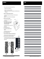
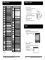
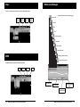
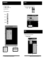
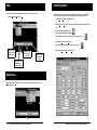
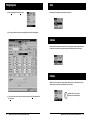
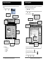
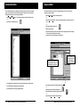
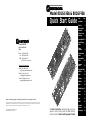
®
Model 801GC-ISA & 801GF-ISA
Quick Start Guide
Index
Page
Installation
2
Start-Up
3
Connecting to
Generator
4
Buttons, Icons,
Messages
5
Create New File 6
®
2111 Big Timber Rd
Elgin, IL 60123-1100
U.S.A.
Phone: (847) 888-0450
Fax: (847) 888-2802
BBS: (847) 888-0115
[≤19.2KB, 8-N-1 protocol]
Format Timing
Editor
7
Timing
Diagrams
8
Custom Image
Editor
9
Command File
Editor
10
Internet Connections:
Sequence
Editor
World Wide Web Site:
http://www.quantumdata.com
SequenceSelect
and Run
12
Sales & Service E-mail:
[email protected]
Reset
13
Calibrate
13
Initialize
13
Gates
14
Technical Support E-mail:
[email protected]
11
Multiple Syncs 14
Entire contents Copyright © 1996 by Quantum Data, Inc. All rights reserved.
The information contained in this document is provided for use by our customers and may not be incorporated into other products or
publications without the expressed written consent of Quantum Data. Information furnished by Quantum Data is believed to be
accurate and reliable. However, no responsibility is assumed by Quantum Data for its use.
801GC-ISA & 801GF-ISA Quick Start Guide
Part # 68-00152 (Rev. B / 20-Mar-96)
This Quick Start Guide is designed to help you get your
generator up and running quickly. Detailed operating
instructions are in the Owner's and Programmer's Manual.
Select
15
Status
15
Step
16
DPMS
16
Standard
Formats
17
TestImages
18
Installation
Notes
Before you install the Quantum Data 801GC-ISA or 801GF-ISA card
1.
■
Determine which port is available for use
■
Determine the correct ISA or base I/O address
■
Make sure the contents of the kit are near your computer so you can follow the steps in order
without stopping.
Make sure your computer and monitor are turned off.
This protects the card from possible electrical damage when you connect your system
components later.
Important — For now, leave the line cord for the computer plugged in.
2.
Remove the cover from the computer.
Power supply
See the manual that came with your computer for
specific instructions.
3.
Touch the metal part of the power supply case
inside the computer to discharge any static
electricity that you might have.
See the manual that came with your computer to locate
its power supply.
4.
Unplug the computer’s line cord.
5.
Locate a full-size, unobstructed slot on your
computer.
See the manual that came with your computer.
6.
Remove the backplate for this slot.
7.
Remove the 801GC-ISA or 801GF-ISA card from its static-proof bag.
Hold the card by its edges to avoid touching the connector on the card.
8.
Prepare the card for your correct ISA or base I/O address.
0
1
2
This is done by placing the provided jumpers in the pattern for your ISA or
I/O shown in this table. The card comes with a default setting of ISA 0
(base I/O 300H).
Jumper
Locations
= jumper in
ISA
Base I/O
(Hex)
ISA 7
268
ISA 6
260
ISA 5
258
ISA 4
250
ISA 3
318
ISA 2
310
ISA 1
308
ISA 0
300
= jumper out
There are two other jumper positions:
X and M. Position X is empty and M
always has a jumper.
GC
•2•
GF
Model 801GC-ISA & 801GF-ISA Quick Start Guide
Model 801GC-ISA & 801GF-ISA Quick Start Guide
• 19 •
Installation – continued
AvailableTestImages
Name
Name
Description
Description
9.
Format
ColorBar
GrayBar
Raster
BriteBox
QuartBox
CheckBy3
Check511
Check_11
Dot_10
P
Details of the format driving the display
S
Details of any format in memory
P
Full height color bars
S
Split field color bars
Focus_Cx
P
Full height gray scale bars
Focus_H
symbols. Include a “Cx” symbol, an
S
Split field gray scale bars
Focus_Oo
“Oo” symbol, the letter “H”, an “@”
P
Active video area set to black pixels
Focus_@6
character in 3 different sizes, a
S
Active video area set to white pixels
Focus_@7
Japanese Kanji “Kan” character,
P
Single white box in center of screen
Focus_@8
S
Adds 4 corner boxes
KanjiKAN
P
White box 1/4 of video area
MEMESony
S
Inverted - black on white
MESony_R
P
P
3x3 b and w checkerboard w/ black box
MESony_G
P
S
3x3 b and w checkerboard w/ white box
MESony_B
P
Blue MEME Sony image on black
P
5 patches of 1 on - 1 off pixels
MEMEPlus
P
White MEME clusters w/ white cross
S
Inverted on a white background
P
Full screen of 1 on - 1 off pixels
S
Inverted (looks almost the same)
MEPlus_R
P
Single pixel white dots on a black
MEPlus_G
background at various densities
MEPlus_B
Dot_12
SMPTE133
P
Based on SMPTE RP-133 pattern
S
Gray scale boxes replaced with
P
Full screen of white characters or
and a “MEME” cluster.
S
Replace the cover on the computer.
Plug in your computer.
14.
Make sure all the cable connections are secure.
Inverted - black on white
P
Red MEME Plus image on black
Blue MEME Plus image on black
2 sizes of white random text
Text_16
S
Reversed text - black on white
size boxes. Partial boxes at edges.
Cubes
P
Orbiting color cubes w/ green frame
S
On white background w/o frame
P
Moving boxes at various speeds
S
Inverted - black boxes on white
Persist
centerline may be different size
Hatch_24o
S
Inverted - black lines and dots
Hatch8x8
P
8x8 box white crosshatch
S
Inverted - black lines
Flat
P
White crosshatch and center patch
FlatGray
All active pixels set to gray
S
Inverted - black lines and patch
Flat_R
All active pixels set to red
Hatch_M
P
Magenta crosshatch and dots on black
Flat_G
All active pixels set to green
Hatch_G
P
Green crosshatch and dots on black
Flat_B
Strokes0
P
Horizontal red, green, and blue lines
Box_50mm
P
50 and 64 mm boxes w/ format data
Strokes1
P
Diagonal red, green, and blue lines
Box_64mm
S
Inverted - black boxes on white
Grill_44
P
Vertical black and white grill lines from
Ramp
P
Full screen gray scale (TV)
4 on - 4 off to 1 on - 1 off
Burst
P
Ref levels plus sine waves (TV)
Horizontal black and white grill lines
TVHatch
P
Crosshatch w/ sine-sq lines (TV)
4 on - 4 off to 1 on - 1 off
PulseBar
P
Sine-sq pulses plus white bar (TV)
Hatch64W
Grill_33
Grill_22
S
Grill_11
Slot
Green MEME Plus image on black
White crosshatches and dots w/ equal
Hatch_12o
Connector
between clusters
S
P
Similar to “i” versions but boxes on
Don't force the card into the slot. If there’s a lot of
resistance, pull it out and try again.
13.
Hatch_10i
P
Don't bend or wiggle the card.
■
12.
P
Hatch_10o
■
Green MEME Sony image on black
Text_9
Inverted - black lines and dots
Handle the card only by its edges.
Red MEME Sony image on black
on a white background
Inverted - black dots on white
S
■
Use the screw to secure the backplate attached to
the card.
S
Hatch_24i
Insert the card into the slot and press the card firmly
until the connector is in place.
11.
Inverted versions - black characters
Dot_24
Hatch_12i
10.
color boxes top and bottom
Align the card with the slot.
Regulate
P
Blinking white box w/ thin border
S
Blinking white box w/ thick border
P
All active pixels set to white
Start-Up
■
Open Windows™, if needed.
■
Insert the Quantum Data Video Generator Manager disk in the disk drive.
■
Select Run from the Program Manager File menu.
■
Type — a:\setup
(if disk is in A drive)
All active pixels set to blue
■
Linearty
P
Crosshatch, circles, and tic marks
TVBar100
P
Color bars @ 100 IRE intensity
Press ENTER or click OK.
LinFocus
P
Crosshatch, w/ center mark, circle and
TVBar_75
P
Color bars @ 75 IRE intensity
■
After a few seconds, a VGM Installation Is Complete message appears.
“@” focus character blocks
Stairs20
P
Gray stairstep @ 20% increments
■
Press ENTER or click OK.
S
Inverted - black on white
SMPTEbar
P
Color bars plus encoder ref. signals
CirclesL
P
Multiple white circles
Outline_0
P
Outline w/ diagonals and center cross
■
The VGM icon appears.
CirclesS
S
Inverted - black circles on white
S
Inverted - black on white
■
P
Outline w/ center cross
Double click on the icon
to begin the program.
S
Inverted - black on white
Outline_1
P = Primary
S = Secondary
• 18 •
Model 801GC-ISA & 801GF-ISA Quick Start Guide
Model 801GC-ISA & 801GF-ISA Quick Start Guide
•3•
Connecting to Generator
■
Connect to your generator.
■
Select Port from the Generator menu.
■
■
Select the correct Com or ISA port.
Click Settings to modify
Com port settings.
AvailableStandardFormats
File Name Video Horiz x Vert
Type Active Pixels
Line
Rate
Frame
Rate
File Name Video Horiz x Vert
Type Active Pixels
1024 x 768
Line
Rate
Frame
Rate
File Name Video Horiz x Vert
Type Active Pixels
1024 x 768
Line
Rate
Frame
Rate
MDA_M7
M2
720 x 350
18.432 49.816
DMT1075
RGB
60.023
75.029
SON1072
RGB
HGC_text
M2
720 x 350
18.141
49.030
DMT1275
RGB 1280 x 1024 79.976
75.025
SON1274
RGB 1280 x 1024 78.855 74.112
57.870 71.799
HGCgraph
M2
720 x 348
18.519
50.051
MAC_TVus
RGB
640 x 480
15.734 29.970•
SON1276
RGB 1280 x 1024 81.206 76.179
CGA_M14
C4
640 x 200
15.700
59.924
MAC_TVos
RGB
512 x 384
15.734 29.970•
INT1160
RGB
1184 x 884
55.200
60.000
EGA_m2
C6
640 x 350
21.851
59.702
MAC_12m
Mono
512 x 384
24.480 60.147
INT1176
RGB
1184 x 884
71.712
76.047
IBM_3179
C3
640 x 400
25.560
60.000
MAC_12c
RGB
512 x 384
24.480 60.147
INT1660
RGB 1664 x 1248 77.940
60.00
IBM_3164
C3
640 x 400
27.648
64.749
MAC_12ce
RGB
560 x 384
24.480 60.147
INT1676
RGB 1664 x 1248 100.73 76.020
AT&T_SVC
C6
640 x 400
25.862
59.866
MAC_13LC RGB
640 x 480
34.975 66.619
BAR2060
RGB 2048 x 2048 126.86
AT&T_IVC
C6
640 x 400
25.862
59.866
MAC_13m
Mono
640 x 480
35.000 66.667
BAR2080
RGB 2048 x 1536 126.86 79.187
AT&T_EVC
C6
640 x 350
25.862
59.866
MAC_13c
RGB
640 x 480
35.000 66.667
BAR2560
RGB
2560 x 2048
126.91
PGA_400
RGB
640 x 400
30.296 59.638
MAC_15
Mono
640 x 870
68.850 75.000
PAL_Y
RGB
920 x 574
15.625 25.000•
PGA_480
RGB
640 x 480
30.296 59.638
MAC_16
RGB
832 x 624
49.107 75.087
PAL_Yus
RGB
768 x 575
15.625 25.000•
VGA_m1
RGB
720 x 350
31.469 70.087
MAC_1960
RGB
1024 x 768
48.193 59.278
PAL_Yos
RGB
640 x 480
15.625 25.000•
VGA_m2
RGB
720 x 400
31.469 70.087
MAC_19
RGB
1024 x 768
60.241 74.927
RS170Y
RGB
752 x 484
15.734 29.970•
VGA_m3
RGB
640 x 480
31.469 59.941
MAC_21
RGB
1152 x 870
68.681 75.062
RS170Yus
RGB
640 x 480
15.734 29.970•
60.008
60.034
VGA_m4
RGB
1024 x 768
35.522 43.478•
NECPC400 RGB
640 x 400
24.823 56.416
RS170Yos
RGB
512 x 384
15.734 29.970•
XGA_m4a
RGB
1053 x 754
35.414 43.453•
NECPC750 RGB
1120 x 750
32.857 40.021•
PAL_4xSC
EYC
910 x 574
15.625 25.000•
XGA_m4b
RGB
1056 x 768
35.602 43.470•
SUN1061
RGB 1024 x 1024 65.267 61.399
PALTV601
EYC
720 x 574
15.625 25.000•
XGA_m5
RGB
1024 x 768
56.287 70.008
SUN1077
RGB
1024 x 768
62.040 77.069
PAL_TVus
EYC
768 x 574
15.625 25.000•
XGA_m6
RGB 1360 x 1024 56.469 51.476•
SUN1166
RGB
1152 x 900
61.796 65.950
PAL_TVos
EYC
640 x 480
15.625 25.000•
XGA6475
RGB
640 x 480
39.375 75.000
SUN116B
RGB
1152 x 900
61.846 66.004
PAL_N
EYC
910 x 574
15.625 25.000•
XGA1076
RGB
1024 x 768
61.080 75.782
SUN1176
RGB
1152 x 900
71.713 76.047
NTSC_443
EYC
752 x 484
15.734 29.970•
IBM6Km1
RGB 1024 x 1024 63.360
60.000
SUN117B
RGB
1152 x 900
71.809 76.149
NTSC4xSC EYC
752 x 484
15.734 29.970•
IBM6Km2
RGB 1280 x 1024 63.363
60.002
SUN1267
RGB 1280 x 1024 71.722 66.718
NTSC_601
EYC
720 x 484
15.734 29.970•
IBM6Km3
RGB 1280 x 1024 70.755
67.003
SUN126B
RGB 1280 x 1024 71.678 66.677
NTSCTVus
EYC
640 x 480
15.734 29.970•
IBM6Km4
RGB
1280 x 1024
70.755
67.003
SUN1276
RGB 1280 x 1024 81.130 76.107
NTSCTVos EYC
512 x 384
15.734 29.970•
VG900601
RGB
800 x 600
35.156 56.250
SUN1667
RGB 1600 x 1280 89.286 66.931
HDTV_1J
RGB 1920 x 1035 33.750 30.000•
VG900602
RGB
800 x 600
37.879 60.317
HP1060
RGB
1024 x 768
47.700
60.000
HDTV_2J
RGB 1920 x 1035 33.750 30.000•
VS900603
RGB
800 x 600
48.077 72.188
HP1070
RGB
1024 x 768
56.476
70.069
HDTV_4J
RGB 1920 x 1035 33.750 30.000•
VS901101
RGB
640 x 480
37.861 72.809
HP1075A
RGB
1024 x 768
62.937
74.925
HDTV_1E
RGB 1920 x 1152 31.250 25.000•
VG901101
RGB
1024 x 768
48.363 60.004
HP1075B
RGB
1024 x 768
60.241
75.020
HDTV_2E
RGB 1920 x 1152 31.250 25.000•
VS910801
RGB
1024 x 768
56.476 70.069
HP1260
RGB 1280 x 1024 63.338
59.979
HDTV_4E
RGB 1872 x 1152 31.250 25.000•
DMT6475
RGB
640 x 480
37.500
75.000
HP1272
RGB 1280 x 1024 78.125
72.005
TEST150
RGB 2048 x 1024 50.403 46.887
DMT8075
RGB
800 x 600
46.875
75.000
HP1275
RGB 1280 x 1024 79.976
75.025
TEST250
RGB 2048 x 2048 79.719 35.861•
Notes
Video Types:
■
Select the appropriate Connector, Baud Rate, Data Bits, Stop Bits, Parity, Flow Control, and
Generator for the Com port only.
■
Click OK.
■
Confirmation appears in the lower right corner.
•4•
Model 801GC-ISA & 801GF-ISA Quick Start Guide
C3 = 3-bit digital color. C4 = 4-bit digital color (CGA). C6 = 6-bit digital color (EGA).
M2 = 2-bit digital monochrome. RGB = separate red green and blue analog color.
Mono = analog monochrome. EYC = analog color television (w/sub-carrier) / S-video (separate lumi and
chroma).
Line and Frame Rates:
The line rates are in units of KHz. The frame rates are in units of Hz. Some rates are rounded to three
decimal places. A bullet (•) after the vertical rate indicates the number is the frame rate for a 2:1 interlaced
format.
Model 801GC-ISA & 801GF-ISA Quick Start Guide
• 17 •
Step …
Buttons, Icons, Messages
The Step … tool lets you move to the next, or previous, saved image or format.
Functions will be discussed on the following pages.
Open from PC
Previous
Format
Next
Format
Previous
Image
Next
Image
Save to PC
Print
Close
Format timing editor
Image editor
Sequence editor
Command file editor
Send file to generator’s memory
DPMS
Receive file from generator
The DPMS screen lets you select various power-saving modes.
Full on
Suspend
Standby
Off
Help or Status Bar
Active Communication
Setting
Active File Name
Model # and
Firmware Revision
• 16 •
Model 801GC-ISA & 801GF-ISA Quick Start Guide
Model 801GC-ISA & 801GF-ISA Quick Start Guide
•5•
CreateNewFile
■
Select New from the File menu.
■
Select the File Type you want to create.
■
Press ENTER or click OK.
Select …
The Select screen lets you select any saved image or format.
■
Choose Select … in the View menu.
or
■
Click on the appropriate icon …
Timing .............
Image ..............
Sequence ........
Command .......
Scroll to select the
desired format or image.
Status
The Status screen displays all the current VGM data.
■
Tool bars float and can
be docked on any side.
Double click to return
to previous position.
•6•
Select Status in the View menu.
It is not necessary to be
connected to a generator
to work on the Editors.
Model 801GC-ISA & 801GF-ISA Quick Start Guide
Model 801GC-ISA & 801GF-ISA Quick Start Guide
• 15 •
Gates
Format Timing Editor
The Gates screen lets you turn individual video elements and sync types on and off.
The Format Timing Editor lets you create or edit timing formats. Any of the active fields can be
modified. This screen also lets you examine the timing diagram for the image(s) you create.
■
Select Gates in the View menu.
■
Select New in the File menu. Then select Format.
or
■
Select Open in the File menu. Then select the existing timing (.fmt) format you want to edit.
or
■
Click on the Timing format editor icon ......
■
Any of the highlighted fields can be edited.
■
Transmit to the generator by clicking on the Send file to generator icon ......
or
■
By selecting Transmit from the File menu.
■
Save the timing format to the PC by clicking on the Save icon .....
or
Image – Draws
alternative versions
of test images.
Sync Gates – Turn
different sync types
on and off.
■
By selecting Save or Save As from the File menu.
Output – Turns all
signal outputs on
and off.
Video Gates – Turn
individual video
elements on and off.
Multiple Syncs
Multiple Syncs in the Tools menu lets you turn on more than one sync at the same time if your
monitor supports it.
• 14 •
Model 801GC-ISA & 801GF-ISA Quick Start Guide
Model 801GC-ISA & 801GF-ISA Quick Start Guide
•7•
Timing Diagrams
■
Select Timing Diagrams from the Tools menu.
■
Click on any horizontal or vertical value to highlight that portion of the timing diagram.
Reset
Reset begins the normal power-on sequence for the generator.
Calibrate
Calibrate compares the generator outputs with an internal precision reference voltage and adjusts
the outputs to ensure that accurate signal swings exit the RGB video and pixel clock outputs.
Initialize
Initialize returns the generator to all factory default settings. ALL user-created data stored in nonvolatile memory is erased and a self calibration cycle is performed.
■
•8•
To turn off and return to video and sync selection, again click on the Timing Diagrams from
the Tools menu.
Model 801GC-ISA & 801GF-ISA Quick Start Guide
!
Initialize erases ALL user-created
data stored in non-volatile memory.
Model 801GC-ISA & 801GF-ISA Quick Start Guide
• 13 •
Sequence Select and Run
Custom Image Editor
As its name implies, the Sequence Select and Run screen lets you select and run any saved
sequence.
The Image Editor lets you create or edit images. You can select any of the existing primitives, and
specify its color, location, and when appropriate, its fill pattern.
■
Select Sequence in the Tools menu.
■
Select New in the File menu. Then select Image.
or
■
Select Open in the File menu. Then select the existing image (.img) format you want to edit.
or
Click on the
desired sequence.
■
Click on the Image editor icon .....
Select a primitive by double
clicking on it in the list box or
by dragging and dropping.
The tool bar is inactive while
you’re in the Sequence Editor.
Enter an image name.
Enter the number of
the sequence step
you wish to display.
Click on to wrap
sequence from
last to first step.
List box updates as
cells are selected.
Headings update for the
primitive selected.
Starts/stops
the sequence.
Move the cursor to Color.
Select the color by double
clicking on it in the list box or
by dragging and dropping.
Manually steps forward
or backward through
the sequence.
Click on to display
sequence step on monitor.
Move the cursor and
enter the desired X
and Y location.
If fills are available for
the primitive, select
the desired pattern.
Reset to first step.
■
Function Keys
•
•
•
•
F1 – Previous step
F2 – Next step
F3 – Start/stop
F4 – Reset
■
If you wish, continue entering other primitives.
■
Transmit the image(s) to the generator and draw it on the monitor by clicking on Draw.
or
■
Click on the Send file to generator icon .......
■
Save the image(s) to the PC by clicking on the Save icon ......
or
■
• 12 •
Model 801GC-ISA & 801GF-ISA Quick Start Guide
By selecting Save or Save As from the File menu.
Model 801GC-ISA & 801GF-ISA Quick Start Guide
•9•
Command File Editor
Sequence Editor
The Command File Editor lets you display and send to the generator any saved format timing,
image, or sequence file. Also new format timing, image, or sequence files can be created by
selecting New in the File menu, then selecting Command.
The Sequence Editor lets you sequence or edit existing images. You have control over each
format, image, mode, and delay.
■
or
■
■
Select Open in the File menu. Then select the existing command (.cmd) file you want.
Select New in the File menu. Then select Sequence.
or
■
Click on the Command editor icon .....
Select Open in the File menu. Then select the existing sequence (.seq) format you want to
edit.
or
■
Click on the Sequence editor icon ......
■
Enter a sequence name.
■
Select the first format you want in the sequence. Move to Image and select the first image.
Then enter the mode and delay for the image.
■
Continue to select and enter images for this sequence.
Formats, images, and sequences
must be named before they can
be downloaded to the generator.
■
Command files are created when you save custom format, image, or sequence files.
■
For ATE applications, download these command files.
■
Command files can be read by any ASCII text editor.
■
List box updates as cells
are selected. Select by
double clicking or by
dragging and dropping.
Transmit by clicking on the Transmit Sequence button.
or
■
By clicking on the Send file to generator icon ....
■
Save the sequence to the PC by clicking on the Save icon .......
or
■
• 10 •
Model 801GC-ISA & 801GF-ISA Quick Start Guide
By selecting Save or Save As from the File menu.
Model 801GC-ISA & 801GF-ISA Quick Start Guide
• 11 •