1
Owners
Manual
FOR POTABLEWATER
HEATING ONLY
NOT SUITABLE FOR
SPACEHEATING
NOT FOR USE IN
MOBILE HOMES
Model
No.
153.335803
-153.335814
-153.335815
153.335844
153.335861
153.335903
_153.335914
--.153.335915
40 Gal. High Altitude
40 Gal.
40 Gal.
40 Gal. High Altitude LP.
40 Gal. L.R
50GaL High Altitude
50 Gal.
50 GaL
153.335941
153.335961
50 Gal. High Altitude LR
50 Gal. L.R
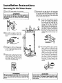
KENMORE
POWER MISER
POWER VENT
GAS WATER HEATER
• Safety Instructions
• Care and Maintenance
• Installation
• Troubleshooting
• Operation
• Parts
TM
8
List
For Your Safety
AN ODORANT
IS ADDED
WATER
HEATER
TO THE
GAS
USED
BY THIS
WARNING: If the information in these instructions are not fol- I
lowed exactly, a fire or explosion may result, causing property
damage, personal injury or death.
I
-Do not store or use gas.oline or other flammable vapors and liquids in the vicinity of this or any other appliance.
-WHAT TO DO IF YOU SMELL GAS
: Do not try to light any appliance.
Do not touch any electrical switch; do not use any phone in your
building.
Immediately
call your gas suppher from a neighbor's phone.
i Follow the gas supplier'sinstructions.
If you can not reach your gas supplier, call the fire department.
-Installation
and service must be performed
service agency or the gas supplier.
Caution:
Read and Follow
All Safety Rules and
Operating Instructions
Before First Use of
This Product.
Savethis Manualfor Future Reference.
Sears, Roebuck
by a qualified installer,
_,WARNING
Improper
installation, adjus_on,
service or maintenance
can cause DEATH, SERIOUS BODILY INJURY, OR PROPERTY DAMAGE. Refer to this.manual
for assistance or consult the local Sears
Serv ce Center or gas utility for further information.
AWARNING
Flammable
vapors may be drawn
i of the structure to this appliance.
by air currents
from
_,WARNING
READ THE GENERAL SAFETY SECTION
BEGINNING
COVER AND THEN THIS ENTIRE MANUAL
BEFORE
OR OPERATING THIS WATER HEATER.
and Co., Hoffman
Estates,
IL 60179
U.S.A.
other
areas
ON INSIDE
INSTALLING
1
I
I
I
I
Safety Precautions
AW,.ARNING
.
.
Imp,roper installation, ad|ustment, alteratlon, service or I
maintenance can cause death, serious bodily injury, or I
property damage. Refer to this manual for assistanceor I
consult your local Sears Service Center for further
information.
AWARNING
WATER HEATERS EQUIPPED FOR ONE TYPE GAS
ONLY: This water heater is equipped for one type gas
only. Check the model rating plate near the gas control
valve for the correct gas. DO NOT USE THIS WATER
HEATER WITH ANY GAS OTHER THAN THE ONE
SHOWN ON THE MODEL RATING PLATE. Failure to
usethe correct gascan causeproblemswhich can result in
DEATH, SERIOUS BODILY INJURY, OR PROPERTY
DAMAGE. If you have any questions or doubts consult
your gassupplier or local utility.
AWARNING
INSTALLATIONS IN AREAS WHERE FLAMMABLE LIQUIDS (VAPORS) ARE LIKELY TO BE PRESENT OR
STORED (GARAGES, STORAGE, AND UTILITY AREAS,
ETC): Flammable liquids (such as gasoline, solvents,
propane (LP) or butane, etc.), all of which emit flammable
vapors, may be improperly stored or used in such areas.
The gaswater heater pilot light or main burner can ignite
such vapors. The resulting flashback and fire can cause
death or serious burns to anyone in the area, as well as
property damage.
If installation in such areas is your only option, then the
installation must be accomplished in a way that the pilot
flame and main burner flame are elevated from the floor
at least 18 inches. While this may reduce the changesof
flammable vapors from a floor spill being ignited, gasoline
and other flammable substancesshouldnever be stored or
used in the same room or area containing a gas water
heater or other open flame or spark producingappliance.
NOTE: Flammable vapors may be drawn by air currents
from other areasof the structure to the appliance.
_,WARNING
If this water heater will be used in beauty shops, barber
shops, cleaning establishments, or self-service laundries
with dry cleaning equipment, it is imperative that the
water heater or water heaters be installed so that combustion and ventilation air be taken from outside these
areas. Refer to the "Locating The New Water Heater"
section of this manual and also the latest edition of the
i National Fuel Gas Code, ANSI Z223.1, also referred to as
I NFPA 54 for specificsprovided concerningair required.
_,WARNING
I
A E_ can start if combustible materials such as clothing, I
cleaningmaterials, or flammable liquidsare placedagainst
or next to the water heater.
_,WARNING
At the time of manufacture this water heater was provided with a combination temperature-pressuros relief vaive
certified by a nationally recognized testing laboratory
that maintains periodic inspection of production of listed
equipment or materials, as meeting the requirements
for Relief Valves and Automatic Gas Shutoff Devices for
Hot Water Supply Systems, and the latest edition of
ANSI Z21.22 and the code requirements of ASME. If
replaced, the valve must meet the requirements of local
codes,but not lessthan a combination temperature and
pressure relief valve certified as meeting the requirements for Relief Valves and Automatic Gas Shutoff
Devices for Hot Water Supply Systems,ANSI Z21.22 by
a nationally recognized testing laboratory that maintains
periodic inspection of production of listed equipment or
materials.
The valve must be marked with a maximum set pressure
not to exceed the marked hydrostatic working pressure
of the water heater (150 Ibs./sq. in.) and a discharge _
capacity not less than the water heater input rate as
shown on the model rating plate. (Electric heaters watts divided by 1000 x 3415 equal BTU/Hr. rate.)
Your local jurisdictional authority, while mandating the
use of a temperature-pressure relief valve complying
with ANSI Z21.22 and ASME, may require a valve model
different from the one furnishedwith the water heater.
Compliance with such local requirements must be satisfied by the installer or end user of the water heater with
a locally prescribed temperature-pressure relief valve
installed in the designatedopening in the water heater in
place of the factory furnished valve.
For safe operation of the water heater, the relief valve
must not be removed from it's designated opening or
plugged.
The temperature-pressure relief valve must be installed
directly into the fitting of the water heater designated
for the relief valve. Positionthe valve downward and provide tubing so that any dischargewill exit only within 6
inches above, or at any distance below the structural
floor. Be certain that no contact is made with any live
electrical part. The discharge opening must not be
blocked or reduced in size under any circumstances.
Excessivelength, over 30 feet, or use of more than four
elbows can cause restriction and reduce the discharge
capacity of the valve.
No valve or other obstruction is to be placed between
the relief valve and the tank. Do not connect tubing
directly to dischargedrain unlessa 6" air gap is provided.
To prevent bodily injury, hazard to life, or property damage, the relief valve must be allowed to discharge water
in quantities should circumstances demand. If the discharge pipe is not connected to a drain or other suitable
means, the water flow may causeproperty damage.
The Discharge Pipe:
Must not be smaller in size than the outlet pipe size of
the valve, or have any reducing couplings or other
restrictions.
Must not be pluggedor blocked.
Must be of material listed for hot water distribution.
Must be installed so as to allow complete drainage of
both the temperature-pressure relief valve, and the
dischargepipe.
Must terminate at an adequate drain.
Must not have any valve between the relief valve and
tank.
Safety Precautions
AWARNING
_WARNING
A gas water heater .cannotoperate properly without the
correct amount of mr for combustion. Do not install in a
confined area such a closet, unless you provide air as
shownin the "Locating The New Water Heater" section.
Never obstruct the flow of ventilation air. If you have any
doubts or questionsat all, call your gas company. Failure
to providethe proper amount of combustionair can result
in a fire or explosion and can cause death, serious bodily
injury, or property damage.
This water heater must not be installed directly on carpeting. Carpeting must be protected by a metal or wood
panel beneath the appliance extending beyond the full
width and depth of the appliance by at least 3 inches
(76.2mm) in any direction, or if the appliance is installed
in an alcove or closet, the entire floor must be covered by
the panel. Failure to heed this warning may result in a
fire hazard.
_,WARNING
The power vent water heater requires its own (separate)
venting system. It cannot be connectedto an existing vent
pipe or chimney. It must be terminated horizontallyto the
outdoors. Failure to properly installthe venting system can
result in asphyxiation, a fire or explosion and can cause
DEATH, SERIOUS BODILY INJURY, OR PROPERTY
DAMAGE.
AWARNING
HOTTER WATER CAN SCALD: Water heaters are
intended to produce hot water. Water heated to a temperature which will satisfyclothes washing, dish washing
and other sanmzing needs can scald and permanently
injure you upon contact. Some people are more likely to
be permanently injured by hot water than others. These
includethe elderly, children, the infirm, or physically/mentally handicapped. If anyone using hot water in your home
fits into one of these groups or if there is a local code or
state law requiring a certain temperature water at the hot
water tap, then you must take specialprecautions. In addition to using the lowest possibletemperature setting that
satisfiesyour hot water needs, a means such as a mixing
valve, should be used at the hot water taps used by these
people or at the water heater. Mixing valves are available
at plumbing supply or hardware stores. Follow manufacturers instructions for installation of the valves. Before
changing the factory setting on the thermostat, read the
"Temperature Regulation" section in this manual.
AWARNING
No vent damper installation is compatible with this power
vented water heater design.No vent damper, whether it is
operated thermally or otherwise is to be installed on this
power vented water heater. Alteration of any part of the
factory-furnished vent assemblycouldresultin improper operation due to restriction of flue gases,spillageof flue gases
and may causecarbon monoxide poisoning.
AWARNING
•The applianceand its individualshutoffvalve must be disconnected from the gas supply piping system during any
pressure testing of the gas system at test pressures in
excessof I/2 pound per squareinch (3.5kPa).
•The appliancemust be isolated from the gas supply piping system by closingits individual manual shutoff valve
during any pressure testing of the gas supply piping system at test pressures equal or lessthan I/2 pound per
square inch (3.5kPa).
_,WARNING
Soot build-up indicates a problem that requires correction before further use. Turn "off" gas to water heater
and leave "off" until repairs are made, because failure to
correct the cause of the sooting can result in a fire or
explosion causingdeath, serious bodily injury, or property
damage.
_,WARNING
AWARNING
Chemical vapor corrosion of the flue and vent system
may occur if air for combustion contains certain chemical
vapors. Spray can propellants, cleaningsolvents,refHgera.
tor and air conditioner refrigerants, swimming pool
chemicals, calcium and sodium chloride, waxes, bleach,
and process chemicals are typical compounds which are
potentially corrosive.
BEFORE LIGHTING [PROPANE (L.R) GAS WATER
HEATERS]: Propane (L.R) gas is heavier than air. Should
there be a leak in the system, the gaswill settle near the
ground. Basements, crawl spaces, skirted areas under
mobile homes (even when ventilated), closets and areas
below ground level will serve as pockets for the accumulation of this gas. Before attempting to light or relight the
water heater's pilot or turning on a nearby electrical light
switch, be absolutely sure there is no accumulated gas in
the are_ Search for odor of gasby sniffingat ground level
in the vicinity of the appliance. If odor is detected, follow
steps indicated at "For Your Safety" on the cover page of
this manual then leavethe premises.
AE,WARNING
Obstructed or deteriorated vent systems may present a
serious health risk or asphyxiation.
Safety Precautions continued on page 4.
3
Safety Precautions
AWARNING
I
I
The water heater with draft hood installed must be prop- J
Jerly vented to a chimney which terminates outdoors. I
I Never operate the water heater unlessit is vented to the J
outdoors and has adequate air supply to avoid risks of J
Jimproper operation, explosionor asphyxiation.
AWARNING
J
Vent termination must not be within 4 feet of any items J
such as gas meters, gas valves or other gas regulating J
equipment.
I
ACAUTION
AWARNING
Minimum clearancesbetween the water heater and combustibleconstructionare I" at the sidesand roar, 4" at the
front, and 6" from the vent pipe. Clearance from the top
of the jacket is 18" on most models. Note that a lesser
dimension may be allowed on some models. Refer to the
label on the water heater adjacent to the gascontrol valve
for all cleerance_
_WARNING
I
Do not use this applianceif any part of it has been under J
Jwater. Immediately call a Sears Service Technician to J
inspect the applianceand to replace the gascontrol or any
part of the burner system which hasbeen under water.
J
_E,WARNING
HYDROGEN GAS: Hydrogen gas can be produced in a hot
water system that has not been used for a long period of
time (generally two weeks or more). Hydrogen gas is
extremely flammable and explosive. To prevent the possibility of injury under these conditions,we recommend the
hot water faucet be opened for several minutes at the
kitchen sink before any electrical appliances which are
connected to the hot water system are used(such as a dishwasber or washing machine). If hydrogen gasis present,
there will probably be an unusual sound similar to air
escaping through the pipe as the hot water faucet is
opened. There must be no smoking or open flame near
the faucet at the time it isopen.
AWARNING
INSULATING JACKETS: When installing an external
water heater insulationjacket on a gaswater heater:
DO NOT cover the temperaturo-prossure rolief valve.
DO NOT put insulation over any part of the top of the
gaswater heater.
DO NOT put insulationover the gascontrol valve or gas
control valve/burner cover, or any accessareas to the
burner.
DO NOT let insulation around the gas water heater to
get within 8 inches of the floor (air must get to the
burner).
• DO NOT cover or remove operating instructions, and
safety related warning labelsand materials affixed to the
water heater.
Failure to heed this will result in the possibilityof a fire or
explosion.
WATER HEATERS EVENTUALLY LEAK: Installation of
the water heater must be accomplishedin such a manner
that if the tank or any connectionsshould leak, the flow of
water will not causedamage to the structure. When such
locations cannot be avoided a suitable drain pan should
be installed under the water heater. Drain pans are avalable at your local Sears store. Such a drain pan must be
not greater than I I/2 inches deep, have a minimum
length and width of at least 2 inches greater than the
water heater dimensions and must be piped to an adequate drain. The pan must not restrict combustion air
flow. Under no circumstances is the manufacturer or
Sears to be held liable for any water damage in connecion with this water heater.
Table of Contents
Safety Precautions .............
2-4
Table of Contents ..........................................................................................................
5
Customer l_esponslt_lllUes ............................................................................................
6
Product _pecmcauons ..................................................................................................
6
Materials and Basic Tools Needed ..........................................................................
7
Materials Needed ......................................................................................................................................................................
Basic Tools ................................................................................................................................................................................
7
7
Installation Instructions ...............................................................................................
8-20
Removing the Old Water Heater ...............................................................................................................................................
8
Locating the New Water Heater ..........................................................................................................................................
9-10
Combustion Air and Ventilation .............................................................................................................................................
10
Venting Clearances .............................................................................................................................................................
10
Combustion Air and Ventilation for Appliances jn Unconfined Spaces ...................................................................................
11
Combustion Air and Ventilation for Appliances in Confined Spaces .......................................................................................
11
Water Piping ...........................................................................................................................................................................
12
Temperature-Pressure Relief Valve...........................................................................................................................................
13
Filling the Water Heater ..........................................................................................................................................................
14
Wiring ...............................................................................................................................................................................
14-15
Venting ..............................................................................................................................................................................
15-18
Gas Piping ..............................................................................................................................................................................
19
Installation Checklist ..............................................................................................................................................................
20
"Uperatmg
"-"
Instructions .................................................................................................
21-24
Eighting .............................................................................................................................................................................
Temperature
Remalation...
J
0
' ......................................................................................................................................................
22-23
24
Service and Adjustment ...............................................................................................
25-27
Tank (Sedimen0 Cleaning ......................................................................................................................................................
Venting System Inspection ......................................................................................................................................................
Oiling Instructions ..................................................................................................................................................................
Burner Inspection ...................................................................................................................................................................
Burner Cleaning .....................................................................................................................................................................
L.P. Gas Control Valve & Burner Assembly Replacement Information ....................................................................................
Draining .................................................................................................................................................................................
Temperature-Pressure Relief Valve Operation ..........................................................................................................................
Drain Valve Washer Replacement
....................
Housekeeping .........................................................................................................................................................................
Service ....................................................................................................................................................................................
25
25
25
25
25
26
26
26
97
27
27
"_ 11 "
"lrout)Jestiootmg
Guide .................................................................................................
28-30
Condensation .........................................................................................................................................................................
Smoke/Odor ...........................................................................................................................................................................
Thermal Expansion .................................................................................................................................................................
Strange Sounds .......................................................................................................................................................................
Smelly Water ...........................................................................................................................................................................
Air in Hot Water Faucets ........................................................................................................................................................
High Temperature Shut OffSystem ........................................................................................................................................
Not Enough Hot Water ..........................................................................................................................................................
Water is too Hot .....................................................................................................................................................................
Leakage Checkpoints ..............................................................................................................................................................
28
28
28
28
29
29
29
29
29
30
Parts Order List ..............................................................................................................
32-35
Customer
Responsibilities
Thank You for purchasing a Sears water heater. Properly
This manual contains instructions for the installation, op_ation, and maintenance of the gas-fired water heater. It also
contains warnings through out t_e manual that you must read
and be aware of. All warnings and all instructions are essential
to the proper operation of the water heater and your safety.
Since we cannot put everything on the first few pages, READ
THE ENTIRE MANUAL BEFORE ATTEMPTING TO
INSTALL OR OPERATE THE WATER HEATER.
The installation must conform with the instructions in this
manual; gas company rules; and Local Codes, or in the
absence of Local Codes, with the latest edition of the National
Fuel Gas code, ANSI Z223.1, also referred to as NFPA 54.
This publication is available from your local government or
public library or gas company or by writing NFPA,
Batterymarch Park, Quincy, MA 02269.
If after reading this manualyou have any questions or do not
understand any portion of the instructions, call the Sears
Service Center.
Carefully plan the place where you are going to put the water
heater. Correct combustion, vent action, ana vent pipe installation are very important in preventing death from possible
carbon monoxide poisoning and fires.
Examine the location to ensure the water heater complies with
the "Locating the New Water Heater" section in this manual.
For California installation this water heater must be braced,
anchored, or strapped to avoid falling or moving during an
earthquake. See instructions for correct installation procedures. Instructions may be obtained from your local dealer,
wholesaler, public utilities or California Office of the State
Architect, 400 P Street, Sacramento, CA 95814.
installed and maintained, it should give you years of trouble free service. If you should decide that you want the new water heater professionally installed by Sears call the local Sears Service Center or any
Sears store. They will arrange for prompt, quality installation by Sears
authorized contractors.
Abbreviations Found In This Instruction Manual
A.G.A. - American Gas Association
A.N.S.I. - American National Standards Institute
AWARNING
This gas-fired water heater is design certified by the
American Gas Association Laboratories under American
National Standards for Gas Water Heaters. The installation must conform with this manual, Local Codes and with
the latest edition of the National Fuel Gas Code, ANSI
Z223.1.
This publicationis availablefrom your focal government or
public library, gas company, or by writing NFPA,
Batterymarch Park, Quincy, MA 02269.
• Read the "Safety Precautions" section, pages 2 and 3 of this
manual first and then the entire manual carefully. If you dont
follow the safety rules, the water heater will not operate properly. It could cause DEATH, SERIOUS
BODILY INJURY
AND/OR PROPERTY DAMAGE.
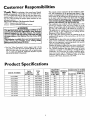
Product
Specifications
40,000
RECOVERY
RATE GALS.
PER HOUR
@ 90°F RISE
40.9
MINIMUM
VENT
PIPE
3"
NATURAL
40,000
40.9
40
NATURAL
40,000
153.335844
40
PROPANE
153.335861
40
PROPANE
TYPE
OF
GAS
153.335803
TANK
CAPACITY
IN GALLONS
40
NATURAL
153.335814
40
153.335815
MODEL NUMBER
B.ZU.
RATE
DIMENSIONS IN INCHES
HEIGHT TO
DIAMETER
JACKET TOP
18"
60"
3"
18"
60"
40.9
3"
18"
60"
40,000
40.9
3"
18"
60"
40,000
40.9
3"
18"
60"
3"
20"
59½"
153.335903
50
NATURAL
40,000
40.9
153.335914
50
NATURAL
40,000
4O.9
3"
20"
59½"
153.335915
50
NATURAL
40,000
40.9
3"
20"
59½"
153.335941
50
PROPANE
40,000
40.9
3"
20"
59½"
40,000
40.9
3"
20"
59½"
153.335961
50
PROPANE
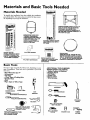
Materials and Basic Tools Needed
Materials Needed
To simplify the installation Sears has available the installation
_larts shown below. You may or may not need all of these materis, depending on your type of installation.
f
Gas
Water Heater
Installation
Kit
WATER HEATER STAND 24"x24"x18"
FOR USE WITH WATER HEATERS
INSTALLED IN RESIDENTIAL
GARAGES HAVING A DIAMETER 24"
OR LESS AND A RATED CAPACITY 75
GALLONS OR LESS
/
EXPANSION
TANKS FOR
THERMAL EXPANSION
CONDITIONS
AVAILABLE IN
2 GALLON AND 5 GALLON
CAPACITY THROUGH
LOCAL SEARS STORE OR
SERVICE CENTERS
WATER HEATER
INSTALLATION
KIT WITH
FLEXIBLE CONNECTORS
FOR 3/4" GALVANIZED
OR
I/2"COPPER PLUMBING
PVC VENT
HEATER
WITH
ELBOW
(
()
PVC VENT
FLEXIBLE WATER
GAS CONNECTOR
FITTINGS
EXTENSION
WATER HEATER HEAT
TRAPS HELP REDUCE HEAT
LOSS DUE TO THERMAL
SYPHONING
DRAIN PANS
AVAILABLE IN 20" DIAMETER FOR
WATER HEATERS HAVING A DIAMETER 18" OR LESS AND AVAILABLE IN
28" DIAMETER FOR WATER HEATERS
HAVING A DIAMETER 26" OR LESS
Basic Tools
You may or may not need all of these tools, depending on your
type of installation. These tools can be purchased at your local
Sears store.
ADDITIONAL
TOOLS NEEDED
WHEN SWEAT SOLDERING
Pipe Wrenches (2) 14"
Screwdriver
Tin Snips
6 Foot Tape of Folding Rule
Garden Hose
Drill
• Pipe dope or Teflon Tape
PropaneCutters
Torch or Hacksaw
i Tubing
Soft Solder
• Solder Flux
_ Wire
EmeryCIoth
Brushes
HACKSAW
GARDEN
HOSE
6 FOOT TAPE
PIPE
WRENCH
SLOT-HEAD
314" WIRE BRUSH
SCREWDRIVER
I/2" WIRE BRUSH
PHILLIPS
SCREWDRIVER
PROPANE
TORCH
TIN SNIPS
ROLL OF LEAD FREE
SOFT SOLDER
ROLL OF TEFLON TAPE
(USE ONLY ON WATER
CONNECTIONS)
PIPE DOPE (SQUEEZE TUBE)
(USE FOR WATER AND
GAS CONNECTIONS)
DRILL
ROLL OF EMERY
CLOTH
7
SOLDER
FLUX
TUBING
CUTTER
Installation
Instructions
Removing the Old Water
Q
Turn "OFF"
Heater
the gas supply to the water heater.
AWARN,.
Q
1
If the main gas line--all
gas appliances isl
used, also shut "off" the gas at each appliance. Leave all [
gas appliances shut "off" until the water heater installation I
is complete,
Disconnect
the vent pipe from the draft hood where
they connect to the water heater. In most installations
the vent pipe can be lifted off after any screw or other
attached devices are removed. Dispose of the draft
hood. The new water heater has the draft hood which
must be used for proper operation.
l
G
®
the water to the water
OTurn
heater. Some installations
requite that
the water be turned off to the entire
_OWP
®
a. If you have copper piping to the water
heater, the two copper water pipes can
be cut with a hacksaw approximately
four inches away from where they connect to the water heater. This will avoid
cutting
off the pipes
too short.
Additional cuts can be made later if necessary. Disconnect the temperature-pressure relief valve drain line. When the
water heater is drained, disconnect the
hose from the drain valve. Close the
drain valve. The water heater is now
completely disconnected and ready to be
removed.
_9
house,
If you have galvanized pipe to the water
heater, loosen the two galvanized pipes
with a pipe wrench at the union in each
line. Also disconnect the piping remaining to the water heater. These pieces
should be saved since they may be needed when reconnecting
the new water
heater. Disconnect the temperature-pressure relief valve drain line. When the
water heater is drained, disconnect the
hose from the drain valve. Close the
drain valve. The water heater is now
completely disconnected and ready to be
QCheck
again to make sure the gas supply
is "OFF" to the water heater. Then disconnect the gas supply connection from
the gas control valve.
Q
Attach a hose to the water heater drain
valve and put the other end in a floor
drain or outdoors. Open the water heater
drain valve. Open a nearby hot water
faucet which will relieve pressure in the
water heater and speed draining.
removed.
......
AWARNING
I
The water passingout of the drain valve may be extremely I
hot. To avoid being scalded,make sure all connectionsare [
[ tight and that the water flow is directed away from any I
I pers°n"
I
ACAUTION
I
Mineral buildupor sediment may have accumulated in the }
old water heater. This causesthe water heater to be much I
heavier than normal and this residue, if spilled out, could
causestaining.
Installation
Instructions
Locating the New Water
Heater
5. The location selection must provide adequate clearances for
servicing and proper operation of the water heater.
You should carefully choose an indoor location for the new water
heater, because the placement is a very important consideration
for the safety of the occupants in the building and for the most
economical use of the appliance. This water heater is not for
use in mobile homes or outdoor installation.
Whether
replacing an old water heater or putting
the water
heater in a new location, the following critical points must be
observed.
1. The location selected should be indoors as dose as practical
to the vent termination
point, and as centralized with the
water piping system as possible. The water heater, as all water
heaters, will eventually leak. Do not install without adequate
drainage provisions where water flow will cause damage.
2. The vent piping cannot exceed a total of 35
vertical and horizontal runs and have no more
It cannot slope downward and horizontal runs
foot rise. All horizontal runs require adequate
feet intervals.
feet including
than 3 elbows.
require ¼" per
support at 3½
3. The water heater requires its own (separate) venting system.
It cannot be connected to an existing ventpipe or chimney.
It must terminate horizontally to the outdoors. Whenever
possible terminate the vent on the leaward side of the building. NOTE: Condensation may be created, at times, as the
combustion gases exit the vent cap and discoloration of
surfaces in proximity to the vent cap may occur.
AWARNING
The powerventwater heaterrequiresitsown (separate)venting
system.It cannotbe connectedto an existingventpipeor chimney.It mustbeterminatedhorizontally
to theoutdoors.Failureto
properlyinstallt_ ventingsystemcanresultin asphyxiation,a Ere
or explosionandcancauseDEATH,SERIOUSBODILY INJURY,
OR PROPERTYDAMAGE.
4. The water laeater comes equipped with a 5 foot power cord
which can be used to connect to a 110/120 volt power
source if (1) local codes allow, and (2) there is a three prong
receptacle available.
AWARNING
]
Do not usean extensioncord.If tbere is not a suitablereceptacle and/or localcodesprohibituseof a powercord,fieldwiringI
mustbe provided.
I
ACAUTION
WATER HEATERS EVENTUALLY LEAK: Installationof the
water heater must be accomplished in such a manner that if
the tank or any connectionsshouldleak, the flow of water
will not causedamageto the structure. When suchlocations
cannot be avoided,a suitable drain pan should be installed
under the water heater. Drain pans are available at your
localSearsstore. Sucha drain pan musthe not greater than
1½inchesdeep, havea minimum length and width of at least
2 inchesgreater than the water heater dimensionsand must
be piped to an adequate drain. The pan must not restrict
combustion air flow. Under no circumstancesis the manufacturer or Searsto be held liable for any water damage in
connectionwith this water heater.
AWARNING
INSTALLATIONSIN AREASWHERE FLAMMABLELIQUIDS
(VAPORS) ARE LIKELY TO BE PRESENT OR STORED
GARAGES, STORAGE, AND UTILITY AREAS, ETC):
Flammableliquids (suchas gasoline,solvents,propane(LP) or
butane, etc.), all of which emit flammable vapors, may be
improperlystoredor usedin sucharea_ The gaswater heater
)notlight or main burnercanignite suchvapor_The resulting
8ashbeckand fire cancausedeathor seriousburnste anyonein
the area,aswell aspropertydamage.
If installationin such areasisyouronlyoption,then the instanation must be accomplished in a way that the pilot flame and
mainburnerflameare elevatedfrom the Boorat least18inches.
While this may reducethe changes
of flammable vaporsfrom a
floor spillbeingignited,gasolineand other8ammablesubstances
shouldneverbe storedor usedin the sameroom or area containinga gaswater heater or other open8ame or sparkpnxlucingappliance.
NOTE: Flammablevaporsmay be drawnbyair currentsfrom
otherareasof the stngtore to the appliance.
AWARNING
Propellantsof aerosol spraysand volatile compounds,(ci_mers, chlorinebasedchemicals,refrigerants,etc.) in additionto
being highlyflammablein many cases,will also changeto corrusive hydrochloricacid when exposedto the combustion
productsof the water heater.The resultscan be hazardous
and alsocauseproductfailure.
AWARNING
This water heater must not be installeddirectlyon carpeting.
Carpeting must be protected by a metal or wood panel
beneath the appliance extending beyondthe full width and
depth of the appliance by at least3 inches(76.2mm) in an)
direction,or if the applianceis installedin an alcove or closet
the entirefloor mustbe coveredby the panel.Failureto bee<
this warningmay result in a Erehazard.
AWARNING
Minimum clearancesbetween the water heater and c_mbustibleconstructionare I" at the sidesand rear,4" at the
front, and 6" from the ventpipe.Clearancefrom the top of the
jacketis 18"on mostmodelgNote that a lesserdimensionmay
be allowedon some models Refer to the labelon the water
heater adjacentto the gascontrolvalvefor all clearance_
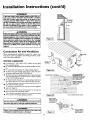
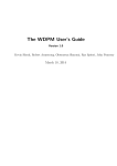
VENTILATION
AIR
O
OPENINGS
6" MIN.
_l}t
IjIN"
TOP VIEW
OF CLOSET
WITHOUT DOOR
i_" MAX.
[# MIN.
FRONT
_l
,
TOP VIE_CV1" MIN.
OF CLOSET
WITH DOOR
VIEW
OF DOOR
[F,g°.I]
1" MIN
41"MIN.
AIR DuCT
Installation
Instructions
(cont'd)
_,WARNING
A gaswnt_ heater cannotoperate properlywithout the correct amountof air for combustion.Do not im_dl in a confined
area sucha closet, unlessyou provide air as shown in the
"Locating The New Water Heater" section.Never obstruct
the flowofventgationair.If you haveanydoubtsor questions
at
all, call your gas company. Failure to provide the proper
amountof combustionair can resultin a fire or explosionand
cancausedeath,seriousbodilyinjury,or propertydamage.
AWARNING
If this water heater will be used in beauty shops,barber shops,
cleaning establishments, or self-service laundries with dry
deaning equipment, it is imperative that the water heater or
water heaters be installed so that combustion and vent_latlou
air be taken from outside these area_ Refer to the "Locating
The New Water Heater" section of this manual and also the
latest edition of the National Fuel Gas Code, ANSI Z223.1, also
referred to as NFPA 54 for specifics provided €oncerning air
required,
Combustion
Air and Ventilation
When determining the installation location
water heater, snow accumulation
and drifting
ered in areas where applicable.
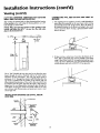
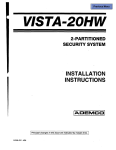
VENTING
•
Figure 2 I
for apower vent
shouldbe
consid-
LESSTHAN
• 120"
CLEARANCES
POWER VENT
TERMINAL
O" clearance for 3" PVC, ABS or CPVC Schedule 40 vent piping
from combustible surfaces.
18" minimumin alldirections from any obstruction that mayinterfere.
•
•
•
•
•
•
•
•
•
12" rain.
FORCED AIR
INLET
12" minimum from the ground, 18" ceiling overhangs. Figure 2.
The Power Vent oudet terminal shall terminate at least 3 feet above
any forced air inlet located within 10 feet. Figure 3a.
The Power Vent outlet terminal shall terminate at least 4 feet below,
4 feet hofizontaUy from or I foot above any door, window or gravity
air inlet into the building. Figure 3a.
18" minimum from other gravity or natural appliance oudet vents
•
o.
,
,
,
,
when direcdy above or 135 to either side of center hne. Figure 3b.
36" minimum from any outlet vents when directly below or 45 ° to
either side of center line. Figure 3b.
36" minimum in all directions from any other forced air appliance
outlet vent. Figure 3b.
The location selection must provide clearances for servicing and
proper operationofthewaterheater.
Figure4.
Vent termination must not be within 4 feet of any items such as gas
meters, gas valves or other gas regulating equipment•
Figure 3a]
f-_
POWERVENT TERMINAL_
/
,'
_/-\\
7_[
_
_
_
[_
/
VENTAPPLIANCE
_/_VENTOR
GRAVITYVENTED
\
; i APPL,ANCE
_-ANY
I Figure
OTHER
OUTLET
VENT
3b I
Must main_Jn
adequate service
a_ WARNING
*THISDIMENSIONIS
INCREASEDTO 36"
WHEN THE VENTOUTLETISFORA FORCED
arid maiRtenance
--- .........
".
///"
"',
Vent termination must not be within 4 feet of any items such as
gas meters, gasvalves or other gas regulating equipment.
AWARNING
I Failure to have required clearances between water beater and
combustible material will result in a fire hazard.
//
/"
"..
L
[ Figure 4 ]
10
..................
Rangeofdegrees
available
forvent
pipe installation.
Installation
Instructions
(cont'd)
Combustion
Air and Ventilation
for Appliances Located in
Unconfined
Spaces
Unconfined Space is a space whose volume is not less than 50 cubic
feet per 1,000 Btu per hour of the aggregateinput rating of all appliances installed in that space. Rooms communicating directly with the
space in which the appliances areinstalled, through openings not furnished with doors, areconsidered a part of the unconfined space.
In unconfined spaces in buildings, infiltration may be adequate to
provide air for combustion, ventilation and dilution of flue gases.
However, in buildings of tight construction (for example, weather
stripping, heavilyinsulated, caulked, vapor barrier, etc.), additionalair
may need to be provided using the methods described in Combustion
Air and Ventilation for Appliances Locatedin Confined Spaces.
Combustion
1. When directly communicating with the outdoors, each opening
shall have a minimum free area of 1 square inch per 4,000 BTU
per hour of total input rating of all equipment in the enclosure.
(See Figure6.)
2. When communicating with the outdoors through vertical ducts,
each opening shall have a minimum free area of I square inch
per 4,000 BTU per hour of total input rating of all equipment in
the enclosure. (See Figure 7.)
VENTILAT_
LO_I:_
Air and Ventilation
for Appliances Located in
Confined Spaces
Ir_=T AIR DOfff
Confined Space is a space whose volume is less than 50 cubic feet per
1,000 Btu per hour of the aggregate input rating of all appliances
installed in that space.
a. ALL AIR FROM INSIDE BUILDINGS:
(See Page 8 Figure 1, and Figure 5 below)
The confined space shall be provided with two permanent openings communicating directly with an additional room(s) of sufficient volume so that the combined volume of all spaces meets the
criteria for an unconfined space. The total input of all gas utilization equipment installed in the combined space shall be considered
in making this determination. Each opening shall have a minimum
free area of one square inch per 1,000 BTU per hour of the total
input rating of all gas utilization equipment in the confined space,
but not less than 100 square inches. One opening shall commence
within 12 inches of the top and one commencing within 12 inches
of the bottom of the enclosure.
I Figure 7 ]
VENT TO
]O_O0_S
,,,,,,,,,,,,,,,,A,,,I
3. When communicating with the outdoors through horizontal
ducts, each opening shall have a minimum free area of 1 square
inch per 2,000 BTU per hour of total input rating of all equipment in the enclosure. (See Figure8.)
CEt4T TO
_LrrlxX;_$
Figure 8 1
4. When ducts are used, they shall be of the same cross-sectional area
as the free area of the openings to which they connect. The minimum short side dimension of rectangular air ducts shall nor be
less than 3 inches. (See Figure 8.)
I Figure 5 [
5. Louvers and Grilles: In calculating free area, consideration shall be
given to the blocking effect of louvers, grilles or screens protecting openings. Screens used shall not be smaller than ¼ inch mesh.
If the free area through a design of louver or grille is known, it
should be used in calculating the size opening required to provide
the free area specified. If the design and free area is not known, it
may be assumed that wood louvers will be 20-25 percent free area
and metal louvers and _rilles will have 60-75 percent free area.
Louvers and .grilles shall be fixed in the open position or interlocked with the equipment so that they are opened automatically
during equipment operation.
b. ALL AIR FROM OUTDOORS:
(see Figures 6-8)
The confined space shall be provided with two permanent openings, one commencing within 12 inches of the top and one commencing within 12 inches from the bottom orthe enclosure.
The openings shall communicate directly, or by ducts, with the
outdoors or spaces (crawl or attic) that freely communicate with
the outdoors.
6. Special Conditions
Created b7 Mechanical
Exhausting
or
Fireplaces: Operation of exhaust fans, ventilation systems, clothes
dryers or firefplaces may create conditions requiring special attention to avoica unsarisfactory operation of installed gas utilization
eqmpment.
Figure 6 1
11
Installation
Water
Instructions
Piping
AWARNING
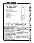
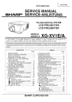
2. Look at the top cover of the water heater. The cold water
inlet is markedcold.
Put two or three turns of teflon tape
around the threaded end of _e threaded-to-swear
coupling
and around both ends of the ¾ threaded nipple. Using flexible connectors, connect the cold water pipe to the coldwater
inlet of the water heater.
HOTTER WATER CAN SCAL_. Water heaters are intended to
produce hot water. Water heated to a temperatu_ which will
satisfyclothes washing, dish washing,and other sanitizing needs
can scald and pen_anently injure you upon contact, Some peode a_e more like/y to be permanently injured by hot water (_w1n
other_ These indude the elder_, children, the infirm, or physicak
ly/mentally handicapped.If anyone usinghot water in your home
Etsinto one of these groups or if thore is a local code or state law
_
(cont'd)
a c_ain _ra_rau_
NOTE: This water heater is insulated to minimize heat
loss from the tank. Further reduction in heat loss can be
accomplished by insulating the hot water lines from the
water heater.
wat_- at the hot wa_erta_ th_
_u must take spechl preca_on_
In addition to using the
possible
temperatu_ settingthat satisfiesyour hot water needs,
l a means such as a mixing valve, shouldbe used at the hot water
taps used by these people or at the water heote_. Mbdng valves
are availableat plumbing supplyor hardware store_ Follow manufacturers instructions for installation of the valves. Before
changing the factory setting on the thermostat, read the
'_remperatore Regulation" section in this manual
INSTALLATION
COMPLETED USING
SEARS INSTALLATION
KIT
COLD INLET
WATER LINE
THREADED TO
SVVEATCOUPUNG
This water heater shall not be connected to any heating systems
or component(s) used with a non-potable water heating appliance.
THREADED TO
SVVEATCOUPLING
If a water heater is installed in a closed water supply system;
such as one having a back-flow preventer, check valve, water
meter with a check valve, etc.., in the cold water supply; means
shall be provided to control thermal expansion. Contact
the
local utility or local Sears Service Center on how to control this
situation.
SHUTOFF
VALVE
3/4" THREADED
NIPPLE
TEMPERATUREPRESSURERELIEF
VALVE
HOT OUTLET
TO HOUSE
NOTE: To protect against untimely corrosion of hot and
cold water fittings, it is strongly recommended that didectric unions or couplings be installed on this water heater
when connected to copper pope.
NIPPLE
The illustration shows the attachment of the water piping to the
water heater. The water heater is equipped with 3/4inch water
connections.
DISCHARGE PIPE
(Do not cap or plug)
NOTE: If using copper tubing, solder tubing to an adapter
before attaching
the adapter to the cold water inlet connection. Do not solder the cold water supply line directly to the
cold water inlet or it will harm the dip tube.
PROVIDE A 6" AIR
GAP BETWEEN THE
END OF THE
DISCHARGE PIPE
AND DRAIN
1. Look at the top cover of the water heater. The hot water outlet is
marked hot. Put two or three turns of teflon tape around the
threaded end of the threaded-to-sweat coupling and around both
ends of the ¾" threaded nipple. Using flexible connectors, connect the hot water pipe to the hot water outlet on the water
heater.
12
Installation
Instructions
Temperature-Pressure
(cont'd)
Relief Valve
AWARNING
AWARNING
At the time of manufacturethis water heater was provided
with a combinationtemperature-pressures
relief valvecertified
by a nationally recognized testinglaboratory that maintains
periodicinspec_onof productionof listedequipmentor materials, as meeting the requirements for Relief Valves and
AutomaticGasShutoffDevicesfur Hot Water SupplySystems,
and the latest edition of ANSI Z21.22 and the code requirementsof ASME. If replaced, the valvemust meet the _luirementsof localcedes,but not lessthan a combinationtemperature and pressurerelief valvecertifiedas meetingthe requiremeritsfur ReliefValvesandAutomatic GasShutoffDevicesfor
Hot Water SupplySystems,ANSI 7.21.22bya nationallyrecognizedtestinglaboratorythat maintainsperiodicinspectionof
productionoflistedequipment or materials
The valvemust be markedwith a maximum set pressurenot
to exceedthe marked hydrostaticworking pressureof the
water heater (150 IbsJsq.in.) and a dischargecapacitynot less
than the water heater input rate asshownon the modelrating
plate. (Electric heaters- watts dividedby 1000x 3415 equal
BTU/Hr. rate.)
Yourlocaljurisdictionalauthority,whilemandatingthe useof a
temperature-pressure
reliefvaivecomplyingwith ANSI Z21.22
and ASME,may require a valvemodel differentfrom the one
furnishedwith the water heater.
Compliancewith suchlocalrequirementsmust be satisfiedby
the installeror end userof the water heaterwith a locallyprescribedtemperature-pressure
relief valveinstalledin the designated openingin the water heater in placeof the factory furnishedvalve.
Forsafeoperationof the water heater,the reliefvalvemustnot
beremoved from it'sdesignatedopeningor plugged.
The temperature-pressure
relief valvemustbe installeddirectly
intothe fittingof thewater heaterdesignated
for the relief valve.
Positionthe valvedownwardand providetubingsothat any dischargewill exit onlywithin 6 inchesabove,or at any distance
belowthe structuralfloor.Be certainthat no contactis made
with anyliveelectricalpart. The discharge
openingmustnot be
blockedor reduced in size underany circumstancesExcessive
length,over 30 feet, or useof more than fourelbowscancause
restrictionandreducethedischarge
capacityofthevalve.
No valveor otherobstructionisto be placedbetweenthe relief
valveand the tank. Do not connecttubing directlyto discharge
drainunless
a 6"air gapisprovided.
Topreventbodilyinjury,hazard to life,or propertydamage,the relief valvemustbeallowed
to discharge
water in quantitiesshouldcircumstances
demand.If
the dischargepipeisnot connectedto a drainor othersuitable
means,the waterflowmaycausepropertydamage.
The DischargePipe:
• Must not be smaiierin sizethan the outlet pipe sizeof the
valve,or haveany reducingcouplings
or otherrestrictions.
• Mustnot be pluggedor blocked.
• Mustbeof materiallistedfor hot water distribution.
• Must be installedsoas to allowcompletedrainageof both
the temperature-pressurerelief valve, and the discharge
pipe.
• Mustterminateat an adequatedrain.
• Mustnot haveanyvalvebetween the relief valveand tank.
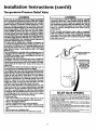
The temperature-pressure relief valve must be manually
operated at least once a _
Caution shouldbe taken to
ensurethat (I) no one is in front of or aroundthe outiot of
the temperature-pressure relief valvedischargeI'me,and (2)
the water manually dischargedwill not cause any bodily
mjury or property damage because the water may be
ex_mely hot.
If after manually oper_Jng the valve, it fails to completely
reset and continuesto releasewater, immediately closethe
cold water inlet to the water heater, follow the draining
instructions, and replace the temperatore-preasure relief
valvewith a new one.
TEMPERATURE-PRESSURE
RFJJEF VALVE
HOT
(Do not cap or plug)
PROVIDE
A 6" AIR
GAP BETWEEN
THE END OF THE
DISCHARGE
PIPE
AND DRAIN
RELIEFVALVEOPENING
At the time of manufacture, this water heater was provided with a cornbinadonternperature-pressure relief valve listedas complyingwith the standardfor relief valves and
automatic gas shut-off devices for hot water supply systems, ANSI Z21.22. For safe
operation of the water heater,the relief valvemust not be removed from its designated
point of installationor plugged.
Your local jurisdictional authority, while mandating the use of a temperature-pressure
relief valve complyingwith ANSI Z21.22 and ASME, may require a valvemodel different
from the one furnishedwith the water heart.
Compliancewith such local requirements must be satisfied by the installeror end user
of the water heater with a locally prescribedtemperature-pressure relief valve installed
in the designated opening in the water heater.
See manual heading-"Temperature-Pressure Relief Vahres"for installationand maintenance of relief valve, dischargeline, and other safetyprecautions.
13
Installation
Instructions
Filling the Water
Heater
You must provide all wiring of the proper size outside of the
water heater. You must obey local codes and electric company
requirements when you install this wiring.
ACAUTION
Never usethis water heater unlessit iscompletelyElledwith
water, To preventdamageto the tank, the tank must be Elled
with water. Water must flow from the hot water faucet
before turning "ON" gasto the water heater,
If you are not familiar with electric codes and practices, or if you
have any doubt, even the slightest doubt, in your ability to connect the wiring to this water heater, obtain the service of a competent electrician or contact your local electric utility.
To fill the water heater with water:
Close the water heater drain valve by turning the handle to
the right (clockwise). The drain valve is on the lower front of
the water heater.
• Open the cold water supply valve to the water heater.
NOTE: The cold water supply valve must be left open
when the water heater is in use.
• To insure complete filling of the tank, allow air to exit by
opening the nearest hot water faucet. Allow water to run
until a constant flow is obtained. This will let air out of the
water heater and the piping.
• Check all new water piping for leaks. Repair as needed.
AWARNING
WATER HEATERS EQUIPPED FOR ONE TYPE VOLTAGE
ONLY: Thiswater heaterisequippedfor 1101120
voltsonly.DO
NOT USE THIS WATER HEATER WITH ANY VOLTAGE
OTHER THAN THE ONE SHOWN ABOVE.Failureto usethe
correctvoltage cancauseproblemswhichcanresultin DEATH,
SERIOUSBODILY INJURYOR PROPERTYDAMAGE. If you
havenayquestionsor doubtsconsultyour electriccompany.
A CAUTION
If wiring from the fuse box or circuit breaker box was aluminum for the oldwater heater,replace it with copperwire.
If you wish to reuse the existing aluminum wire, havethe
connectionat the water heater made by a competent electrician. Contact a localelectrical contractorand/or the local
electric utility.
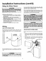
Wiring
USE WITH
POWER
CORD
USE WITHOUT
The water heater comes equipped with a 5 foot power cord
which can be used to connect to a 110/120 volt power source if,
(1) local codes allow, and (2) there is a three prong receptacle
available.
POWER
CORD
If power cord cannot be used, then follow these wiring instructions.
\
\
\
\
\
\
\
\
\
\
\
(cont'd)
1. Provide a way to easily shut off the electric power when working on the water heater. This could be with a circuit breaker
or fuse block in the entrance box or a separate disconnect
switch.
5' MAXIMUM
CORD LENGTH
(Factory supplied)
2. Install and connect a circuit directly from the main fuse or
circuit breaker box. This circuit must be the right size and
have its own fuse or circuit breaker.
\
\
\
You must provide all wiring, (1) to a receptacle or, (2) between
the water heater and junction box when the power cord is nor
used.
GREEN
GROUND SCREW
_,WARNING
]
Do not usean extensioncord.If there isnot a suitablerecepta-J
tie and/or localcodesprohibituseof a powercord,fieldwiringI
must be provided,
J
14
Installation
USE WITHOUT
POWER
Instructions
CORD
(cont'd)
3. A standard ½" conduit opening has been made in the water
heater junction box for the conduit connection.
4. Use wire nuts and connect the power supply wiring
wires "ns'de the water heaters junction box.
to the
5. The water heater must be electrically
_grounded"
installer. A green ground screw has been provided
by the
on the
WIRING
(cont'd)
water heater's junction box. Connect ground wire to this
location. For complete grounding
details and all allowable
exceptions,
refer to the latest edition
of the National
Electrical Code.
6. Replace
provided.
the
wiring
junction
cover
using
the
screw
DIAGRAM
SgflT_4
S_T_H
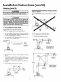
Venting
_WARNING
I
•,WARNING
To insureproperventingof this gas-Ered
water heater,the cot- I
rect vent pipe diameter must be utilized. Any additions of I
other gas appliances on vent with this water heater will
adverselyaffectthe operationofthe water heater.
near foot.
All vent gases must be completely
structure (dwelling).
The combustion
and ventilation
,,
vented to the outdoors of the
air flow must not be obstructed.
a_WARNING
I
The water heater with draft hood installed must be properly I
vented to a chimney which terminates outdoors. Never oper_e the water heater unlessit isvented to the outdoors and has
adequate air supply to avoid risks of improper operation explo-
Min. rise I/4"
per foot
sion or asphyxiation.
&WARNING
I
The vent pipe from the water heater must be 3 diameter I
PVC schedule 40 pipe and must slope upward I/4 inch per
A, WARNING
Failureto haverequiredclearances
betweenwater heater and
combustiblematerialwillresult in a fire hazard.
I
Obstructed or deteriorated vent systems may present a serious
health risk or asphyxiation.
15
Installation
Instructions
(cont'd)
Venting (cont'd)
VENTING
SYSTEM
FOR ALL MODELS
AWARNING
Be sure vent pipe is p,_porly connected to prevent escape of
dangerousflue gaseswhich could causedeadly asphyxiation,
EXAMPLE
INSTALLATIONS
The vent piping cannot under any circumstances be run downhill.
AWARNING
Chemical vapor corrosion of the Rue and vent system may
occur if air for combustion contains certain chemical vapors,
Spray can propellants, cleaning solvents, refrigerator and air
conditioner refrigerants, swimming pool chemicals, calcium
and sodium chloride, waxes, bleach, and process chemicals are
typical compoundswhich are potentially corrosive.
3" PVC SCHEDULE
Supplied
in the carton
1. A 3" PVC Schedule
40 VENT PIPING
with the water heater
are:
40-45 ° vent cap with wire screen.
2. A 3" PVC Schedule 40-90 ° street ell; used to connect the
vent pipe to the water heater when the vent pipe is to be
turned horizontally directly off the blower.
The vent piping can be installed as follows:
1. No more than 3 elbows can be used.
3. A 5' section of 3" PVC Schedule 40 pipe
required and must be supplied locally).
(more
may be
Max. 3
3"opvc
Schedule40
90 Elbow
MIN. RISE ¼"
PER FOOT
Vent Cap with
Screen
TOTAL VERTICAL AND
HORIZONTAL RUNS
CANNOT EXCEED 35'
1
1. The water
system.
heater
requires
its own
(separate)
venting
MAX_3
2. 3" PVC, ABS or CPVC Schedule 40 piping and fittings are
acceptable materials for the vent system on all 40 gallon
models and 50 gallon 40,000 BTU/HR models.
3. It cannot
chimney.
be connected
to existing
vent
piping
MIN. RISE ¼"
PER FOOT
or
MAX. 20'
4. It must terminate horizontally to the outdoors.
TOTAL VERTICAL AND
HORIZONTAL RUNS
CANNOT EXCEED 35'
MIN. RISE ¼"
PER FOOT
16
Installation
Instructions
VENTING SYSTEM EXAMPLE
FOR ALL MODELS (cont'd)
INSTALLATIONS
(cont'd)
CEMENTING PVC, ABS OR CPVC PIPE AND FITHNGS
Read and observe all safety information
cleaner, and cement containers.
2. Horizontal runs require a minimum ¼" rise per foot.
printed on primer,
DANGER
Primer, cleaner, and cements are extremely flammable.
They are harmful or fatal if swallowed. The vapors are
harmful. They may irritate eyes and skin and can be
absorbed through the skin.
35' Max.
16" MIN.
13" MIN.
PRECAUTIONS
Always store primers, cleaner, and cements in cool, dry,
well ventilated places. Do not store them near heat,
sparks, or flames. Keep containers closed. Use them in
well ventilated areas. Wear impervious clothing while
handling. Do not smoke, eat, or drink while handling.
Wash thoroughly after handling and before eating. Wear
eye protection when handling. If swallowed, drink water,
do not induce vomiting, and call a physician or poison
control center immediately. If inhaled, get fresh air and
seek medical attention if ill feelings persist. In case of
eye and skin contact, immediately flush with plenty of
water for 15 minutes and seek medical attention if irritation persists. KEEP OUT OR REACH OF CHILDREN.
Min. rise ¼"
per foot
I1" MIN.
3. A vertical run can be no more than 20'.
4. The total vertical and horizontal run cannot exceed 35'.
All primers, cleaners, and cements must meet all local codes and
applicable
standards of the American Society For Testing
Materials Standards.
Min. rise ¼"
One Elbow
perfoot
Before using primers, cleaners, and cements, stir or shake, makin sure contents are liquid. Do not use if found to be lumpy or
jei_;-like.
Ma_ 20'
1. Cut pipe ends squarely removing
TOTAL VERTICAL AND
HORIZONTAL RUNS
CANNOT EXCEED 35'
all burrs and dirt.
2. Dry fit pipe and fittings to be connected
for proper fit.
3. Clean pipe and fitting with a primer/cleaner.
4. Apply a thin coat of cement
inside.
I
6. QUICKLY assemble parts while cement
too long, re-coar pipes.
7. Push pipe completely
until it bottoms.
puddling
is fluid! If you wait
into socket of fitting, turning
as it goes
8. Hold pipe and fitting together for 30 seconds. Then carefully
clean off excess with a cloth. Allow connections a sufficient
time to cure before disturbing.
Min. rise ¼"
per foot
9. Remember
supported.
Max.20'
that vent pipes must be adequately
APPROXIMATE
OINTS
Min. rise ¼"
per foot
avoiding
5. Apply a liberal coat of cement to pipe leaving no voids.
I
T
to fitting,
TOTAL VERTICAL AND
HORIZONTAL RUNS
CANNOT EXCEED 35'
90°F to 150°F
50°F to 90°F
0°F to 50°F
I
17
SETTING
TIME
MOVEMENT
OF JOINT
3Ahr.
1 hr.
1_ hr.
and securely
FOR 2½" TO 4" PIPE
COMPLETE
SET
8 hrs.
15 hrs.
18 hrs.
Installation
Instructions
(cont'd)
Venting (cont'd)
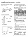
CUTTING
OPENING
THROUGH
AN OUTSIDE
WALL AND COLLAR INSTALLATION
CONNECTING
BLOWER
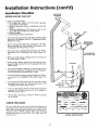
After reading the manual and you have determined the location
of the opening in the wall, (using the drawing below), cut a 3½"
hole through an exterior wall.
NOTE: When determining location of the opening in the
outside wall allow for the ¼" rise per foot that has taken
place in the horizontal run.
• a 3 " PVC or ABS Schedule 40
1. The manufacturer has supphed
street elbow for connection to the water heater when turning
immediately horizontally off the blower• Place the elbow in
the required direction on the blower and usinl_ 3 sheet metal
screws, attach the elbow. If using a galvanized elbow attachment is the same.
CL of Flue--_ .......
_
PVC, ABS OR CPVC PIPE VENT TO
"_[_t
?-
I
40 gal.-60"
50 Gal.- 59½"
2.
_r
The Y' PVC Schedule 40 vent pipe can be run from the water
heater through the wall or from the wall to the water heater,
whichever is most convenient.
The vent pipe must extend a
minimum of 1½" through the exterior wall. Extending the vent
cap as far as possible from the surface of the exterior wall will
help minimize discoloration of the wall in this area which may
be caused by the flue gases. Note that the inside collar must be
slipped over the vent piping before locating the pipe through the
wall. Before securin_ the inside and outside collars to the wall,
use a silicone sealer between pipe and opening to insure a water
and air tight seal.
INSTALLATION
CPVC PIPE
SHOWING USE OF PVC, ABS OR
SEALER
SILICONE_
__ 1 +h" MIN.EXTENSION
THROUGH
EXTERIOR
WALL
SCREW
SCREEN
VENT CAP MUST BE
SEALER
_
DOWNWARD
POSITIONED
18
I
If there is to be a vertical run of vent from the blower, the 3"
PVC, ABS or galvanized pipe must be attached to the blower
using 3 sheet metal screws. If using galvanized piping attachment is the same. Additionally, you must seal all joints using a
suitable silicone sealer such as GE RTV-103 or equivalent.
Installation
Instructions
(cont'd)
Gas Piping
I
AWARNING
]
Make sure the gassure
type listed on the I
model rating plate. The inlet gaspressuremust not exceed
14 incheswater column 'Apoundper squareinch(3.5kPa)]. I
The minimum inlet gaspressurelistedon the model rating I
f
plate isfor the purposeof input adjustment.
A sediment trap shall be installed as close to the inlet of the
water heater as practical at the time of water heater installation.
The sediment trap shall be either a tee fitting with a capped nipple in the bottom outlet or other device recognized as an effective sediment trap. If a tee fitting is used, it shall be installed in
conformance with one of the methods of installation shown
below.
AWARNING
AWARNING
J
Use pipe joint €omp_tape
marked as beingI
resistantto the actionof petroleum [Propane(LR)] gese_ 1
SEDIMENT
, J
If the gascontrolvalveissubjectedto pressuresexceeding'A
pound per square inch(3.5kPa), the damage to the gas control valvecouldresult in a fire or expiosionfrom leakingga_ J
TRAP
Connecting the gas piping to the gas control valve of the water
heater can be accomplished by either of the two methods shown.
AWARNING
If the main gasline shutoffservingall gasappliancesis used,
alsotorn "off" the gasat each appliance.Leaveall gasappliancesshutoff until dm water heater installationiscomplete.
GAS PIPING
WITH
FLEXIBLE
CONNECTOR
A gas line of sufficient size must be run to the water heater.
Consult the latest edition of National Fuel Gas Code ANSI
Z223.1, also referred to as NFPA54 and the gas company concerning pipe size.
MANUAL
_('AS
SUPPLY PIPING
SHUTOFF
VALVE
FLEXIBLE G_S CONNECTOR
LABELED AS COMPLYING
WITH ANSI STANDARDS
There must be:
•A readily accessible manual shut off valve in the gas supply line
serving the water heater, and
•A drip leg (sediment trap) ahead of the gas control valve to help
prevent dirt and foreign materials from entering the gas control
GROUND
UNION (Optional)
GAS
CONTROL
VALVE
ValVe.
DRIP LEG
(Sediment trap)
•A flexible gas connector or a ground joint union between the
shutoffvalve and control valve to permit servicing of the unit.
CAP
Be sure to check all the gas piping for leaks before li_hting the
water heater. Use a soapy water solution, not a match or open
flame. Rinse offsoapy solution and wipe dry.
GAS PIPING WITH ALL BLACK
PIPE TO GAS CONTROL
Standard Models are for installation up to 3,300 feet above sea
level.
High Altitude Models are for installation from 3,300 to 5,500
feet above sea level.
Ifa standard model is installed above 3,300 feet or a high altitude
model is installed above 5,500 feet, the input rating must be
reduced at the rate of 4 percent for each 1,000 feet above sea level.
Contact your local Sears Service Center or gas utility for further
information.
SHUTOFF
VALVE
MANUAL_;ASSUPPLY
IRON
PIING
BLACK PIPE
GROUND lOIN1
UNION
GAS
CONTROL
VALVE
T
6"
The appliance and its gas connection must
AWARNING
be leak tested
beforeplacingthe appliancein operation.
DRIP LEG
(Sediment
t_ap)
CAP
&WARNING
AWARNING
Contaminants in the gaslinesmay causeimproper operation
of the gascontrol valvethat may result in fire or explosion.
Beforeattachingthe gasline be sure that all gaspipe isclean
on the inside.To trap any dirt or foreign material in the gas
supply line, a drip leg (sometimes called a sediment trap)
must be incorporated in the piping.The drip leg must be
readily accessible.Installin accordancewith the "Gas Piping"
section.Refer to the latest edition of the National Fuel Gas
Code,ANSI Z223.1,also referred to as NFPA 54.
• The applianceand its individualshutoffvalvemust be disconnectedfrom the gassupplypipingsystemduringanypressure
testing of the gassystem at test pressuresin excessof I/2
poundper squareinch(3.5kPa).
• The appliancemust be isolatedfrom the gassupplypipingsystem by closingits individualmanualshutoffvalveduringany
pressuretestingof the gassupplypipingsystemat test pressures equalor lessthan I/2 pound per squareinch(3.5kPa).
19
Installation
Instructions
Installation
Checklist
BEFORE LIGHTING
THE PILOT:
•
(cont'd)
VENT PIPETO
OUTDOORS
Check the gas lines for leaks.
a. Use a soapy water solution. DO NOT test for gas leaks
usinga match or open flame.
b. Brush the soapy water solution on all gas pipes, joints and
fittings.
c. Check for bubbling soap. This means you have a leak.
Turn OFF gas andmake the necessary repairs.
d. Recheck for leaks.
e. Rinse off soapy solution and wipe dry.
COLD
SHUTOFF
VALVE
Is the new temperature-pressure
relief valve properly installed
and piped to an adequate drain? See "Temperature-Pressure
Relief Valve" section.
TEt4PERATUREPRESSURERELIEF
VALVE
Are the cold and hot water lines connected
to the water
heater correctly?
See "Water Piping" instructions
in the
"Installing the New Water Heater" section.
•
Is the water heater completely filled with water? See "Filling"
instructions
in the "Installing the New Water Heater" section.
•
Will a water leak damage anything?
New Water Heater sectmn.
See the "Locating
DISCHARGE PIPE
the
Is there proper clearance between the water heater and anything that might catch fire? See the "Locating the New water
Heater section.
Do you have adequate ventilation so that the water heater
will operate properly? See ' Combust'on A'r and Vent'lation"
in the 'Locating the New Water Heater" sect'on.
Is the draft hood vent piping properly secured? See "Venting"
instructions
in the "Installing the New Water Heater" section.
Is there proper clearance between the vent pipe and anything
that might catch on fire? See 'Venting
instructions in the
"Installing the New Water Heater" section.
(Sediment trap)
PIPECAP
Is the vent pipe properly sloped and does the vent terminate
outdoors? See "Venting" instructions
in the "Installing the
New Water Heater" section.
Do you need to call your gas company to check the gas pipe
and its hookup?
CHECK
FOR
LEAKS
Be sure to check all your gas pipes for leaks before lighting your
water heater. Use a soapy water solution, not a match or open
flame. Check the factory gas,,fittings after pilot is lit and gas control knob is still in PILOT
position. Then, check the fittings
when the main burner is turned "ON". Use a soapy water solution for this, too.
MODEL RATING PLATE
20
Operating
Instructions
-
This water heater is equipped with an electrically operated venting system and a standing pilot. For the burner to come on, the
water heater thermostat must call for heat. Then the system will
begin sequencing, each section proving itself before gas is
allowed to flow to the burner.
BEFORE
THE
WATER
HEATER
WILL
BLOWER MOTOR
OPERATE:
VENTING
RESET SVVITCH
1. The control system must be connected to a 110/120 volt
power supply. The control system has an overall rating of 2
amps. The water heater must be securely and adequately
grounded in accordance with local codes and with the latest
edition of the Nationa! Electrical Code ANSI/NFPA 70.
DRAFT HOOD
2. The ON/OFF toggle switch, located on the control box
above the thermostat must be in the "ON" position for the
electrical control system to operate allowing the gas portion
to operate (ignite burner).
3. The pilot must be lit. See Lighting instructions on page 22
of this manual or located adjacent to the thermostat on the
water heater.
ON/OFF SWITCH
AIR PRESSURE
, SWITCH
4. The gas control knob located on the thermostat
must be
turned to the "ON" position for the gas to be able to flow.
5. The venting manual reset switch must be in the dosed position. See Venting Manual Reset Switch in the For Your
Information Section".
6. There
is a non-resettable
hi-limit
which must be good (dosed)
ated. See 'High Temperature
Your Information Section".
switch
in the thermostat,
for the thermostat
Shut Off System
24V/120V
to be o_erin the For
TRANSF_
GAS CONTROL
KNOB,
GAS PRESSURE
SWITCH
OPERATION
When the thermostat calls for heat, gas in allowed to flow to a
(Normally open) pressure switch closing it. An electrical circuit
is then made to the blower, turning it on. The indicator light
located on the control box will come on. When the blower has
achieved sufficient venting, the airpressure switch will dose and
the indicator light will go off. A 24volt circuit will be completed through the venting manual reset switch and on to the 24
volt gas valve located just below the thermostat. The 24 volt gas
valve will open allowing gas to flow to the burner. The standing
pilot will establish a main burner flame.
BURNER
GAS THERMOSTAT
THERMOCOUPLE
21
Operating
Instructions
Lighting
A, WARNING
BEFORE LIGHTING
[PROPANE
(L.R) GAS WATER
HEATERS]: Propane (I.R) gas is heavier than air. Should there
be a leak in the system, the gas will settle near the ground.
Basements, crawl spaces, skirted areas under mobile homes
(even when ventilated), closetsand areas below ground leve_will
serve as pockets for the accumulation of this gas. Before
attemp_ng to light or relight the wZer heater's pilot or turning
on a nearby electrical light switch, be absolutely sure them is no
accumulated gas in the area. Search for odor of gasby miffing at
ground level in the vicinity of the appliance. If odor is detected,
follow steps indicated at "For Your Safety" on the cover page of
this manual then leave the premises.
Figure 9 ]
Lighting and operating instructions are located on front of the
water heater, above or to one side of the gas control valve.
AWARNING
AN ODORANT IS ADDED TO THE GAS USED
BY THIS WATER HEATER.
FOR YOUR SAFETY
IF YOU SMELL GAS:
Do not try to light any appliance.
Do not touch any electrical switch; do not use any phone in
your building.
Immediately caJlyour gas supplier from a neighbor's phone.
Follow the gas supplier_sinstructions.
If you cannot reach your gas supplier, call the fire department.
Figure 10]
_,WARNING
DO NOT force the gascontrol knob. Use only your handto
pushit downto light the pilot, or to tom it to "ON", "OFF"
or "PILOT". Never usea tool suchas a lever,wrench or pliers. Do not hit or damage the knob. A damagedknob may
result in an explosionand seriousinjury. If you haveproblem
turningthe knob, call the gassupplier immediately.
CHECK
Figure I I]
FOR LEAKS
INNER DOOR
Be sure to check all your gas pipes for leaks before lighting your
water heater. Use a soapy water solution, not a match or open
flame. Check the factory gas ,fittings after pilot is lit and gas control knob is still in PILOT
pos!tion,, Then, check the fittings
when the main burner is turned
ON . Use a soapy water solution for this, too.
OUTER
Figure 12]
22
DOOR
Operating
Instructions
Lighting label on the water
FOR YOUR
(cont'd)
heater as it appears above the thermostat
SAFETY
READ
BEFORE
LIGHTING
m
If you do not follow these instructions exactly, a fire or explosion
WARNING
I
may result causing property damage, personal injury or loss of life.
A. This appfiancehas a pilot which mustbe lightedby
hand.Whenlightingthe pilot,followtheseinstructions
exactly.
B. BEFORELIGHTINGsmellall aroundtheappfiancearea
for gas. Be sure to smell next to the floor because
somegas is heavierthanafr andwillsettleon thefloor.
WHATTO DOIF YOUSMELLGAS
• Do nottry to lightanyappliance.
• Do not touch any electric switch; do not use any
phonein yourbuilding.
• immediatelycall yourgas supplierfroma neighbor's
phone.Followthegassupplier'sinstructions.
LIGHTING
INSTRUCTIONS
1. STOP!Readthesafetyinformationaboveon thislabel.
2. TurnON/OFFswitchon controlbox to "OFF".
3. Remove outer door covering gas thermostat and
burnerassembly.(Figure12, Page22)
r_:
4. Set the thermostat to lowest setting
by turning the watertemperaturedial
clockwise,(,f-'_) to its lowesttemperature setting (with arrow on dial) as
shown. DO NOT FORCE. (Figure 9,
Page22)
5. Turngas controlknobclockwiseV ) to "OFF" position. Knob cannot be turned from "PILOT" to "OFF"
unlessknobis depressedslightly.DO NOT FORCE.
6. Wait five (5) minutesto clear out any gas. If you then
smell gas, STOP!Follow"B" in the safetyinformation
above on this label. If you don't smell gas, go to the
nextstep.
7. Remove(or open) inner door located belowthe gas
controlunit.
8. Find pilot-followmetaltubefrom gascontrol.Thepilot
is locatedon the righthandsideof theburner.
PILOT BURNER
• If you cannot reach yourgas supplier,call the fire
department.
C. Useonlyyour handto pushin or tum the gascontrol
knob. Neverusetools. If the knobwill not pushin or
turn byhand,don'ttry to repair it, call a qualifiedservice technician.Forceor attemptedrepairmay result
in a fire or explosion.
D. Do not use this applianceif any part has been under
water.Immediatelycall a qualifiedservicetechnician
to inspecttheapplianceandto replaceanypart of the
controlsystemand any gas controlwhichhas been
underwater.
__THERMOCOUPLE
9. If you don't smell gas, turn knob on gas control
10.Push in control knob all the way and hold down.
Immediatelylight the pilot with a match. Continue
to hold control knob in for about one (1) minute
after the pilot is lit. Release knob and it will pop
back up. Pilot should remain lit. If it goes out,
repeat steps 5 through 10.
• If knob does not pop up when released, stop
and immediatelycall your service technicianor
gas supplier.
• If the pilot will not stay lit after several tries,
depres_ and turn the gas control knob clockwise _'_
to "OFF" andcall yourservicetechnicianor gassupplier.(Figure9, Page22)
11.Replaceinnerdoor.(Figure12,Page22)
12.At armslengthaway,turn gas controlknobcounterclockwise_
to the full "ON" position. WARNING
Do not use gas control knob to regulate gas
flow. (Figure11,Page22)
13.At arms lengthaway,set the thermostatto desired
setting.The mark('V) HOT indicativeof approximate
120°Fispreferredstartingpoint.Somelocallawsmay
require a lower starting point. If hotter water is
desired,seainstructionmanualand "warning" below.
14.Replacetheouterdoor.(Figure12,Page22)
15. TurnON/OFFswitchon controlboxto "ON".
counter-clockwise
J_@ to "PILOT"position.(Figure9,
Page22)
WARNING
Hotter water increasesthe risk of scald injury. Beforechanging temperaturesetting see instructionmanual.
TO TURN
OFF GAS TO APPLIANCE
1. Turn ON/OFF switch on controlbox to "OFF".
2. Remove outer door covering gas thermostat and
burner assembly.(Figure 12, Page 22)
3. Set the thermostat to lowest setting
by turning the water temperature
dial clockwise (f-_)
to its lowest
temperaturesetting (with arrow on dial)
as shown.DO NOT FORCE. _
4. Turngascontrolknobclockwise_" ":o"OFF" position. Knobcannotbe turnedfrom "PILOT" to "OFF"
unlessknobis depressedslightly.DO NOT FORCE.
(Figure9, Page22)
5. Replaceouterdoor.(Figure12,Page22)
23
Operating
Temperature
Instructions
(cont'd)
Regulation
Turn the water temperature dial dockwise _f"-_)
to decrease
the temperature, or counterclockwise (4 r _) to increase the
temperature.
Due to the nature of the typical gas water heater, the water tem_oerature in certain situations
may vary up to 30°F higher or
wen at the point of use such as, bathtubs, showers, sink, etc.
This means that when the temperature adjustment dial is set at
the mark approximating 120 ° F, the actualwater temperature at
any hot water tap could be as high as 150°F or as low as 90°E
Any water heater's intended purpose is to heat water. Hot water
is needed for deaning (bodies, dishes, clothing). Hot water will
present a scald hazard. Depending on the time element, and the
people involved (normaladults,
children,
toddlers,
elderly,
infirm, etc.) scalding may occur at different temperatures.
AWARNING
HOTTER WATER CAN SCALD:,Water heatersare intendedto
pmducohot water. Water heatedto a temperaturewhichwill
satisfyclotheswashing,dishwashing,and other sanitizingneeds
canscaldand permanentlyinjureyou uponcontact.Some people am more likelyto be permanentlyinjuredbyhot water than
otherL Theseincludethe elderl_children,the infirm,or physically/mentally handicapped.
If anyoneusinghot water in yourhome
fitsintooneofthesegroupsor iftham isa localcodeor statelaw
requiringa certaintemperaturewater at the hotwater tap,then
youmust takespecialpmcau_on_In uddidonto usingthe lowest
possibletemperaturesettingthat satisfies
your hotwater needs,
a meanssuchas a mixingvalve,shouldbe usedat the hot water
tapsusedby these peopleor at the water heater Mixingvalves
are availableat plumbingsupplyor hardwarestore_Followmanufacturers instructionsfor installation of the valves. Before
changing the factory setting on the thermostat, read the
'_remperatureRegulation"sectioninthismanual.
•
HOT-Is
a thermostat setting of approximately 120°F, which
will supply hot water at the most economical
temperatures.
The temperature adjustment knob
can be turned lower than "HOT" if desired.
A-Is a thermostat setting of approximately 130°E
B-Is a thermostat setting of approximately 140°E This is the
lowest setting for supply of hot water to dishwashers.
C-Is a thermostat
VERY HOT-Is
_,WARNING
setting of approximately
150°E
a thermostat setting of 160°E It is recommended that the dial be set lower whenever possible.
Never allow small childrento usea hot water tap, or to draw
their own bath water. Never leavea childor handicappedpe_
son unattendedin a bathtubor shower.
A, WARNING
Should overheatingoccur or the gassupplyfall to shot off,
torn OFF the manualgascontrolvalveto the appliance.
The thermostat
of this water heater has been factory set at its
lowest position, to reduce the risk of scald injury. It is adjustable
and must be reset to the desired temperature setting. The mark
(•) HOT indicative of approximately
120°F is the preferred
startin_ point. Some states have a requirement for a lower setting. Ityou need hotter water, follow directions for temperature
adjustment, but beware of the warnings in this section.
24
Service
and Adjustment
Tank (Sediment)
Burner Inspection
Cleaning
Sediment build-up on the tank bottom may create varying amounts of
noise, and if left in the tank will cause premature tank failure. In some
water areas, you may not be able to drain all sediment deposits by
simply draining the tank. In these cases Mag Erad (part no. 3515) can
be used to help remove the sediment deposits. This may be order_
from the Sears Service Center. For ordering, refer to the "Repair Parts
section.
Venting System
AWARNING
Do not use this appliance if any part of it has been under water
I Immediately call a Sears Service Technician to inspect the
appliance and to replace the gas control or any part of the
[ burner system which hasbeen underwater.
I
I
[
I
At least once a year a visual inspection should be made of the
main burner and pilot burner. The drawing is for your reference.
Inspection
You should check for sooting which is not normal and will
impair proper combustion.
At least once a year a visual inspection should be made of the
venting system. You should look for:
• Obstructions
which could cause improper venting. The combustion and ventilation air flow must not be obstructed.
Damage or deterioration
which could cause improper venting
or leakage of combustion products.
Rusted flakes around top of water heater.
_,WARNING
t
Chemical vapor corrosion of the flue and vent system may
occur if air for combustion contains certain chemical vapors.
Spray can propellants, deaning solvents, refrigerator and air
conditioner refrigerants, swimming pool chemicals, calcium
and sodium chloride, waxes, bleach, and processchemicals are
typical compounds which are potentially corrosive.
_,WARNING
.
]
Soot build-up indicates a problem that requires correction |
before further use. Turn "off" gas to water heater and leaveI
"off" until repairs are made, .becausefailure to correct the[
cause of the soo_ng can result m a fire or explosion causing|
death, serious bedlly injury, or property damage.
I
AWARNING
Obstructed or deteriorated vent systems may present a serious
health riskor asphyxiation.
Burner Cleaning
In the event
instructions:
Be sure the vent piping is properly connected to prevent I
escape of dangerous flue gasses which could cause deadly
I
_, .WARNING
I
asphyxiation.
your
burner
needs
cleaning,
use the following
If inspection of the burner shows that cleaning is required, turn
the gas control knob clockwise (t"'-_)
to the OFF posltao ,
depressing slighdy.
I
NOTE: The knob cannot be turned from "PILOT" to "OFF"
unless knob is depressed slightly. DO NOT FORCE.
AWARNING
Loose deposits on or around the burner can be removed by carefully using the hose of a vacuum cleaner inserted through the
access door of the water heater. If the burner needs to be removed
for additional cleaning, call the Sears Service Center to remove
and clean the burner and correct the problem that required the
burner to be cleaned.
If after inspection of the vent system you found sooting or
deterioration, something is wrong. Call the local gas utility to
correct the problem and clean or replace the flue and venting
before resom ng operation of the water h_ter.
Oiling
Instructions
Oil motor every 12 months
with 6 drops of SAE 20 motor oil.
25
Service and Adjustment
L.P.Gas Control Valve & Burner
Assembly Replacement
Information
(cont'd)
Temperature-Pressure
Valve Operation
The temperature-pressure
at least once a year.
Relief
relief valve must be manually operated
_WARNING
PROPANE (L.R) GAS CONTROL VALVE AN BURNER
ASSEMBLYREPLACEMENTINFORMATION.
RELIEF VALVE
For Propane(LR) GasModelsOnly:.
Your water heater is equippedwith a Pmpane (I-R) gascon_ol valveand a main burner assemblywith left handthreads
for the followingfitUngsand their connec_on_
DISCHARGE
•
•
The connection between the manifold and the gas
control valve (A to B) are left hand threads.
The connection between the main burner orifice
and the manifold (C to D) are left hand threads.
PIPE
Failure to install and maintain a new properly listed temperature-pressure relief valve will release the manufacturer
from any
claim which might result from excessive temperature or pressure.
For ordering these replacement parts, please refer to
the "Repair Parts" section of this manual.
AWARNING
If the temperature-pressure relief valve on the appliance
weepsor dischargesperiodically,this may be due to thermal
expansion. Your water heater may have a check valve
installed in the water line or a water meter with a check
valve. Consultthe SearsService Center for further information. Do not plugthe temperature-pressurerelief valve.
AWARNING
When checl_ngthe temperature-pressurerelief valveoperat]on, make sure that (I) no one is in front of or aroundthe
outlet of the temperature-pressurereliefvaivedischargeline,
and (2) that the water manuallydischargedwill not causeany
property damagebecausethe water may be extremely hot.
If after manually operating the valve, it fails to completely
reset and continuesto release water, immediately closethe
cold water inlet to the water heater, follow the draining
instructions, and replace the temperature-pressure relief
valve with a new one.
Draining
The water heater should be drained if being shut down during
freezing temperatures.
Also periodic draining and cleaning of
sediment from the tank may be necessary.
•
•
Turn the _as control knob to the "OFF" position.
CLOSE me cold water inlet valve to the water heater.
OPEN a nearby hot water faucet and leave open to allow for
draining.
Connect a hose to the drain valve and terminate to an adequate drain.
OPEN the water heater drain valve to allow for tank draining.
NOTE: If the water heater is going to be shut down and
drained for an extended period, the drain valve should be
left open with hose connected allowing water to terminate
to an adequate drain.
Close the drain valve.
Follow instructions in the "Filling The Water Heater" section.
Follow the lighting instructions in the "Lighting" section to
restart the water heater.
26
Service and Adjustment
Drain Valve Washer
Replacement
NOTE: For replacement, use a "/_2"• ,3/,, • _,, thick washer
available at your nearest hardware store. For ordering replace•
merit washers, refer to the Ic Repatr• Parts" sectmn.
•
•
•
Turn "OFF" gas supply to water heater.
Follow "Draining"
instructions.
Turning counter clockwise, remove the hex cap below the
screw handle.
Remove the washer mad put the new one in place.
Screw the handle and cap assembly back into the drain valve
and retighten using a wrench. DO NOT OVER TIGHTEN.
Follow instructions
in the "Filling The Water Heater"
section.
Check for leaks.
Follow the lighting instructions in the "Lighting" section to
restart the water heater.
Housekeeping
Vacuum around base of water heater for dust, dirt, and lint on a
regular basis.
Combustible
materials such as clothing, cleaning materials, or
flammable liquids, etc. must not be placed against or adjacent to
the water heater.
To insure sufficient ventilation and combustion air supply, proper clearances from the water heater must be maintained
at all
times.
Service
Before calling for repair service, read the Start Up Conditions
and Operational
Conditions
found in the Troubleshooting
Guide of this manual.
If a condition persists or you are uncertain about the operation
of the water heater, let a qualified person check it out.
Contact SEARS Repair Services at 1-800--4-REPAIR (1-800473-7247).
27
(cont'd)
Troubleshooting
Guide
Start Up Conditions
CONDENSATION
SMOKE/ODOR
Whenever
the water heater is filled with cold water, a certain
amount of condensation
will form while the burner is on. A
water heater may appear to be leakingwhen in fact the water is
condensation. This usually happens when:
• When a new water heater is filled with cold water for the
first time.
• When gas burns and water vapor is produced
in water
heaters, particularly high efficiency models where flue temperatures are lower.
• When you use large amounts of hot water in a short time
and the refill water is very cold.
It is not uncommon
to experience a small amount of smoke and
odor during the initial start-up. This is due to burning off of oil
from metal parts, and will disappear in a short while.
Moisture
from the products
of combustion
condense
THERMAL
Water suppl_ systems may, because of high line pressure, frequent cut-otis, the effects of water hammer and others, have
installed devices such as pressure reducing valves, check valves,
back flow preventers, etc. to control these types of problems.
When these devices are not equipped with an internal by-pass,
and no other measures are taken, the devices cause the water system to be closed. As water is heated, it expands (thermal expansion) and closed systems do not allow for the expansion of heated water.
on the
cooler tank surfaces and form drops of water which may,fall
onto the burner or other hot surfaces to produce a sizzling or
"frying" noise.
The water within the water heater tank expands as it is heated
and increases the pressure of the water system. If the relieving
point of the water heater's temperature-pressure
relief valve is
reached, the valve will relieve the excess pressure. The temperature-pressure
relief valve is not intended for the constant
refi_ of thermal expansion.
This is an unacceptable condition
and must be corrected.
Excessive condensation
can cause pilot outage due to water running down the flue tube onto the main burner and putting out
the pilot.
Because of the suddenness and amount of water, condensation
water may be diagnosed as a "tank leak". After the water in the
tank warms up (about 1-2 hours), the condition should disappear.
It is recommended
that any devices installed which could create
a closed system have a by-pass and/or the system have an expansion tank to relieve the pressure built by thermal expansion in
the water system. Expansion tanks are available for ordering
through the Sears Service Center. Contact the local plumbing
inspector, water supplier, and/or the Sears Service Center for
assistance in controlling these situations.
Do not assume the water heater is leaking until there has been
enough time for the water in the tank to warm up.
An undersized water heater will cause more condensation.
The
water heater must be sizedproperly to meet the family's demands
for hot water including dishwashers, washing machines and
shower heads.
STRANGE
Excessive condensation
may be noticed during the winter and
early spring months when incoming water temperatures are at
their lowest.
SOUNDS
Possible noises due to expansion and contraction of some metal
_arts during periods of heat-up and cool-down do not represent
armful or dangerous conditions.
Good venting is essential for a gas fired water heater to operate
properly as well as to carry away products of combustion
and
water
EXPANSION
Condensation
causes sizzling and popping with the burner area
during heating and coofin_ periods and should be considered
normal. See Condensation
section.
vapor.
AWARNING
HOTTER WATER CAN SCALD:Water heatersareintendedto
,reducehot water.Water heatedto a temperaturewhichwill
satisfyclotheswashing,dishwashing,andother sanitizingneeds
canscald and permanentlyinjureyou uponcontact.Somepeodeare more likelyto be permanentlyinju_l byhot water than
other_ Theseindudethe elderly,children,the infirm,or physically/mant_dlyhandicapped.
If anyoneusinghot water in yourhome
Etsintoone ofthesegroupsor ifthere isa localcodeor statelaw
requiringa certaintomperatore waterat the hotwater _ then
_u musttake specialprecautions.
In additionto usingthe lowest
x_ssibie
temperaturesettingthat satisfiesyourhot water needs,
a meanssuchasa mixingvalve,shouldbe usedat the hot water
tapsusedby these peopleor at the water heater.Mixingvalves
are availableat plumbingsupplyor hardwarestore_Followmanufacturers instructionsfor installationof the valves. Before
changing the factory setting on the thermostat, read the
'TemperatureRegulation"sectioninthismanual.
28
Troubleshooting
Operational
SMELLY
Guide (cont'd)
Conditions
WATER
In each glasslined water heater there is installed at least one
anode rod (see parts section) for corrosion protection of the
tank. Certain water conditions will cause a reaction between this
rod and the water. The most common complaint associated with
the anode rod is one of a "rotten egg smell". This odor is derived
from hydrogen sulfide gas dissolved in the water. The smell is
the result of four factors which must all be present for the odor
to develop:
&WARNING
Shouldoverheatingoccur or the gassupplyfail to shut off,
urn ' OFF" the manual gascontro valveto the app ante.
NOT
a. a concentration of sulfare in the supply water.
b. little or no dissolved oxygen in the water.
c. a sulfate reducing bacteria within the water heater. (This
harmless bacteria is non-toxic to humans.)
d. an excess of active hydrogen in the tank. This is caused by
the corrosion protective action of the anode.
ENOUGH
Do not remove the anode leaving the tank unprotected. By
doing so, all warranty on the water heater tank is voided.
WATER
WATER
FAUCETS
HYDROGEN GAS: Hydrogen gas can be produced in a hot
water system that has not been used for a long period of time
(generally two weeks or more). Hydrogen gas is extremely
flammable and explosive. To prevent the possibility of injury
under these conditions, we recommend the hot water faucet
be opened fur several minutes at the kitchen sink before any
electrical applianceswhich are connected to the hot water sysI tern are used (such as a dishwasher or washing machine), If
hydrogen gas is present, there will probably be an unusual
sound similar to air escapingthrough the pipe as the hot water
faucet is opened. There must be no smoking or open flame
near the faucet at the time it is open.
TEMPERATURE
SHUT
OFF
IS TOO
HOT
1. The temperature adjustment dial may be set too high. See the
"Temperature Adjustment" section.
NOTE: A period of time is necessary after an adjustment has
been made for the water temperature to reach the new temperature setting.
AWARNING
HIGH
WATER
Check the pilot flame. It may have gone out, All models have
the manual
be sure the
it ispilot.
open.
anheck
opening
behind gas
the shut
outeroffvalve
door fortoviewing
If the piiot is not lit, follow the "Lighting" instructions in this
manual or located above the gas control valve on the water
heater to relight the pilot. If the water was extremdy hot and is
now cold, the high limit safety temperature shut off may have
put out the burner and pilot. If the high temperature shut off
activates, the gas controlvalve
must be replaced. Contact the
Sears Service Center.
The gas control knob must be turned to the "ON" position.
:" The temperature adjustment dial may be set too low. See the
Temperature Regulation" section.
The gas company can check the gas input to see if it is correct.
An underfired water heater will not beat water as quicldy.
Look for leaking or open hot water faucets. Make sure all are
dosed.
• The cold water inlet temperature may be colder during the winter months. It will take longer to heat the water and seem like
less hot water.
• If you cannot find what is wrong, call the Sears Service Center.
If the smelly water persists after the anode replacement and chlorination treatment, we can only suggest that continuous chlorination and filtering conditioning
equipment
be considered to
eliminate the water problem.
IN HOT
HOT
i
Smelly water may be eliminated or reduced in some water heater
models by replacing the anode(s) with one of less active material,
and then chlorinating
the water heater tank and all hot water
lines. Contact Sears Service for further information
concerning
an Anode Replacement
Kit #9001453
and this Chlorination
Treatment.
"AIR"
OR NO
2. If lower temperature settings will not lower the water temperature, call the Sears Service Center.
&WARNING
Due to the nature of the typical gas water heater, the
water temperature in certain situations may he hotter
than the thermostat setting.
Short, frequent draws of hot water - especiallywith very
cold incoming water - can shockthe thermostat into brief
operation resulting in hotter and hotter layers of water
closerto the top of the tank.
Changes in hot water usagepatterns or raising the temperature differential between the cut-on of the thermostat and the cold water temperature will usuallyeliminate
the problem.
SYSTEM
This water heater is equipped with an automatic gas shut off system. The high temperature shut off is built into the gas control
valve. This system shuts off the gas supply to the water heater
burners when high water temperatures
are present. It is nonresettable. If the high temperature shut off activates, the gas control valve must be replaced. If this were to occur, turn "OFF" the
entire gas supply to the water heater. Contact the Sears Service
Center.
29
Troubleshooting
Guide
Leakage Checkpoints
Use this guide to check a "Leaking" water heater. Many suspected "Leakets" are not leaking tanks. Often the source of the water
can be found and corrected.
A CAUTION
Read this manual first. Then before checking the water
heater make sure the gas supply has been turned
"OFF", and never turn the gas "ON" before the tank is
comp etely fu of water.
If you are not thoroughly familiar with your local gas codes your
water heater, and safety practices,
contact the
Center to check the water heater.
•,CAUTION
.
J
Never use this water heater unlessit is completely filled
with water. To prevent damage to the tank, the tank I
must be filled with water. Water must flow from the hot I
water faucet before turning "ON" gas to the water t
heater.
Water at the draft hood is water vapor
which has condensed
out of the combustion products. This is caused by a
problem in the vent. Contact the Sears Service Center.
may be seen on pipes in humid
*Condensation
pipe connections may be leaking.
O'The
weather or
primary anode rod fitting may be leaking.
Small amounts of water from temperature-pressure relief
valve may be due to thermal expansion or high water pressure in your area.
®
*The temperature-pressure
the tank fitting.
Water from
slightly.
O'The
drain
a
v_e
relief valve may be leaking at
drain valve may be due
to
the valve opened
may be leaking at the tank fitting.
Combustion products contain water vapor which can condense on the cooler surfaces of the tank. Droplets form and
drip into the fire or run on the fioot. This is common at
the time of startup after installation and when incoming
water is cold.
@
Water in the water heater bottom or on the floor may be
from condensation,
loose connections, or the relief valve.
DO NOT replace the water heater until a full inspection
of all possible water sources is made and necessary corrective steps taken. Leakage from other appliances,
water
lines, or ground seepage should also be checked.
NOTE: To check where threaded portion enters tank,
insert cotton swab between jacket opening and fitting. If
cotton is wet, follow "Draining" instructions in the
"Periodic Maintenance" section and then remove fitting.
Put pipe dope or teflon tape on the threads and replace.
Then follow "Filling the Water Heater" instructions in the
"Installing the New Water Heater" section.
30
Notes
31
POWER
MISER
8 POWER
GAS WATER HEATERS
TM
MODEL
153.335803
"O
VENT
NUMBERS:
153.335814
40 Gal. High Altitude
40 Gal.
153.335815
40 Gal.
153.335844
153.335861
40 Gal. High Altitude
40 Gal. L.E
153.335903
153.335914
50 Gal. High Altitude
50 Gal.
153.335915
50 Gal.
153.335941
153.335961
50 Gal. High Altitude
50 Gal. L.P.
L.P.
0
50
L.P.
mQ
g
Now that you have purchased your Gas Water Heater, should
a need ever exist for repair parts or service, simply contact any
SEARS Service Center or call 1-800-4-REPAIR (1-800-4737247). Be sure to provide pertinent facts when you call or
visit.
11
k_
t,o
All parts listed may be ordered from any SEARS Service
Center, most SEARS stores and by calling 1-800-366-PART
(1-800-366-7247).
If the parts you need are not stocked locally, your order will be electronically transmitted to a SEARS
Repair Parts Distribution Center for handling.
THIS IS A REPAIRPARTS LIST, NOT A PACKING LIST.
The model number of your Gas Water Heater will be found
on the model rating plate located near the gas control valve.
When ordering repair parts, always give the following
information:
Model Number
Part Number
Part Description
Name of Item
"U
Model
KEY
NO.
1.
2.
k_
153.335803
153.335814
153.335815
9001957
9001957
9O01957
9001957
9OO1993
9001993
9001993
9001993
PART DESCRIPTION
Vent Cap
w/Screen
Wall Collar
Numbers
9001957
9001993
153.335915
153.335941
9001957
9001993
9O01957
9OO1957
9001957
9001957
9001993
9001993
9001993
9001958
9001958
9O01993
9OO1958
9OO1959
9001960
9001961
9000736
9001962
9001963
9001699
9000734
9000071
42-33085
IB
3.
4.
5' PVC Schedule 40 Vent Pipe
45 ° PVC Schedule 40 Elbow
9001958
9001958
9001958
9001958
9001958
9001958
9001958
9001959
9001959
9001959
9OO1959
9001959
9001959
90O1959
9001959
9001959
5.
6.
Vent/Blower Adapter
Blower
90O1960
9001960
9001960
9001960
9001960
9001960
9001960
9001960
9001960
9001961
9001961
9001961
9001961
9001961
9001961
9001961
9001961
9000736
9000736
9001961
9000736
9000736
9000736
9000736
9001962
9001962
9001962
9001962
9001962
9001962
9001962
9001963
9001963
9001963
9001963
9001963
9001963
9001963
9001699
9001699
9001699
9001699
9000734
7.
Blower Gasket
9000736
9000736
9000736
8.
9.
10.
11.
Venting Manual Reset Switch
Draft Hood Assembly
Dip Tube
Anode Rod
9001962
9001962
9001963
9001963
12.
Temperature-Pressure Relief Valve
13.
14.
Drain Valve
Inner Door
15.
16.
17.
Pilot Assembly
Burner Assembly
Burner Orifice
(Drill Size)
18.
¼" NPT Close Nipple
19.
20.
21.
Brass Fitting ¼" NPT/¼"cc
¼" / 18" Tube
¼" NIYI' Tee
22.
23.
24.
25.
X" Orifice Fitting
Manifold Connector
24 Volt Gas Valve
Tubing w/Fitting
9001698
9001698
9001698
9001698
9001698
9000734
9000071
42-33085
9000734
9000071
42-33085
9000734
9000071
42-33085
9000734
9000071
42-33085
9000734
9000071
42-33085
9000734
9000071
42-33085
9000734
9000071
42-33085
9000071
42-33085
9000734
9000071
42-33085
9000254
9000254
9000254
9000254
9000254
9000254
9000254
9000254
9000254
9000281
9000281
9000281
9000281
9000281
9000281
9000281
9000281
9000281
9002153
9002157
9002154
9002154
9002153
9002153
9002157
9002154
9000288
9000288
9002153
9000288
9000288
9000288
9000288
0230162
#49
0230141
#36 (HA)
0230120
# 33
0230120
#33
0230128
#51 (HA)
9002147
0230128
#51 (HA)
9002147
9002147
9002147
9002147
9002147
9002147
9002146
9002146
9002146
9002146
9002146
9002146
9002146
9002146
9002151
9002151
9002151
9002151
9002151
9002151
9002151
9002151
9002148
9002148
9002148
9002148
9002148
9002148
9002148
9002150
9000288
9000288
0230141
#36 (HA)
9002147
0230120
# 33
9000288
0230120
#33
9002147
9002146
9002151
9002148
9002148
9002149
9002149
9002149
9002150
9002149
9002149
9001966
9001966
9001966
9002150
9002142
9002149
9002142
9001966
9001966
9001966
9002142
9001967
9001967
9001967
9001967
9001967
9001967
9001967
9001967
9001967
9001968
9001968
9001968
9001968
9001968
9001968
9001968
• These parts are also available at most SEARS retail stores.
** Also available at most hardware stores.
÷ Replaced only on return of damaged plate.
# Not illustrated.
9001968
9001968
t53.335961
153.335914
153.335844
153.335861
153.335903
PART NUMBERS
9000254
9000281
9002154
9000288
0230162
#49
9002147
9002146
9002151
9002148
9002150
9002142
9001967
9001968
O
mo
POWER
MISER** 8 POWER
GAS WATER HEATERS
MODEL
"U
VENT
NUMBERS:
153.335803
153.335814
40 Gal. High Altitude
40 Gal.
153.335815
40 Gal.
153.335844
153.335861
40 Gal. High Altitude
40 Gal. L.E
153.335903
153.335914
50 Gal. High Altitude
50 Gal.
153.335915
50 Gal.
153.335941
153.335961
50 Gal. High Altitude
50 Gal. L.P.
O
L.P.
t
L.E
Now that you have purchased your Gas Water Heater, should
a need ever exist for repair parts or service, simply contact any
SEARS Service Center or call 1-800-4-REPAIR (1-800-4737247). Be sure to provide pertinent facts when you call or
visit.
mo
g
i
_40
39
All parts listed may be ordered from any SEARS Service
Center, most SEARS stores and by calling 1-800-366-PART
(1-800-366-7247). If the parts you need arenot stocked locally, your order will be electronically transmitted to a SEARS
RepairParts Distribution Center for handling.
THIS IS A REPAIRPARTSLIST, NOT A PACKING LIST.
The model number of your Gas Water Heater will be found
on the model rating plate located near the gas control valve.
When ordering repair parts, always give the following
information:
Model Number
Part Number
Part De_dptlon
Name of Item
222
11
"€
Itl
Model
KEY
t.#0
kii
153.335803
153.335814
153.335815
153.335844
Numbers
153.335861
153.335903
153.335914
153.335915
153.335941
153.335961
NO.
PART DESCRIPTION
26.
27.
Thermocouple*
Lower Manifold
42-9231
9001987
42-9231
9001987
42-9231
9001987
42-9231
9002143
42-9231
9002143
42-9231
9001988
42-9231
9001988
42-9231
9001988
42-9231
9002144
42-9231
9002144
28.
Manifold Cover
9001209
9001209
9001209
9001209
9001209
9001209
9001209
9001209
9001209
9001209
29.
Control
30.
Gas Thermostat
31.
32.
Gas Tubing; w/Fittings
ES. Bracket
PART NUMBERS
Cover
9002113
9002113
9002113
9002113
9002113
9002113
9002113
9002113
9002113
9002113
F145-1220
F145-1220
F145-1220
F145-1204
F145-1204
F145-1220
F145-1220
F145-1220
F145-1204
F145-1204
9001972
9001973
9001972
9001973
9001972
9001973
9001972
9001973
9001972
9001973
9001972
9001973
9001972
9001973
9001972
9001973
9001972
9001973
9001972
9001973
33.
Gas Pressure Switch
9001974
9001974
9001974
9002152
9002152
9001974
9001974
9001974
9002152
9002152
34.
Transformer
9001373
9001373
9001373
9001373
9001373
9001373
9001373
9001373
9001373
9001373
35.
36.
Light
On/Off
Switch
9001975
9001773
9001975
9001773
9001975
9001773
9001975
9001773
9001975
9001773
9001975
9001773
9001975
9001773
9001975
9001773
9001975
9001773
9001975
9001773
37.
38.
Pressure Switch
Power Cord
9001976
9001513
9001976
9001513
9001976
9001513
9001976
9001513
9001976
9001513
9001976
9001513
9001976
9001513
9001976
9001513
9001976
9001513
9001976
9001513
39.
Flue Baffle
9001977
9001977
9001977
9001977
9001977
9001978
9001978
9001978
9001978
9001978
40.
Restrictor
9000275
9000275
9000275
9000275
9000275
9000275
9000275
9000275
9000275
9000275
41.
Model Rating Platet
42.
Temperature
#
Manual
#
Mag-Erad
Ring
Adjustment
O
Knob
0270118
0270118
0270118
0270184
0270184
0270118
0270118
0270118
0270184
0270184
F145-0697
F145-0697
F145-0697
F145-0870
F145-0870
F145-0697
F145-0697
F145-0697
F145-0870
F145-0870
* These parts are also available at most SEARS retail stores.
** Also available at most hardware stores.
+ Replaced only on return of damaged plate.
# Not illustrated.
0291325
3515
m@
8
Warranty
a.Adjusting thermostat.
b. Lighting pilot.
c. Leaksin pipes or fittings.
d. Improper venting
e. Condensation
About Your Warranty
THE PRICE OF YOUR WATER HEATER DOES NOT INCLUDE
A FREE CHECKUP SERVICE CALL. On Water Heater lnstalations
Arranged BySears,Searswarrants the installation.
ON INSTALLATIONS NOT MADE BY SEARS AUTHORIZED
CONTRACTORS:
1. YourSearswarranty appliesto the product only.
2. Searsdoes not warrant the installation.
3. A charge will be made on servicecalls due to poor or incomplete
installation.These indude:
This manual is in non-technical language. It may help you avoid the
cost of a needlessservice call. Many servicecalls really aren't needed.
Such aswhen:
1. The gas is turned "OFF'.
2. The pilot is out.
3. A gas or water leak is due to loosepipe or connections.
FULL ONE YEARWARRANTY ON WATER HEATER
For one year from the date of purchase, when your Sears Kenmore water heater is installed and operated in accordance with the
instructions in this manual, Sears will:
1. Repair defects in material or workmanship in this water heater, free of charge.
2. Furnish and install a new current model water heater of closest available capacity and quality, free of charge, if a leak occurs in
the tank.
LIMITED WARRANTY ON TANKS THAT LEAK
After one year and through 8 years from the date of purchase, ira leak occurs in the tank, Sears will furnish a new current model
water heater of closnst available capacity and quality. You will be charged for installation.
LIMITED WARRANTY ON PARTS
After one year and through 4 years from the date of purchase, when your Sears Kenmore water heater is installed and .operated in
accordance with the information in this manual, if a part fails due to a failure in materials or workmanship, Sears wdl furmsh a I
i replacement part free of charge. You will be charged for labor.
If the water heater is subjected to commercial, institutional, industrial or other non-residential use (more than 2 families), the
above warranty coverage for tanks that leak is effective for 2 years from the date of purchase and the above parts warranty is effective for 1 year'from the date of purchase.
To obtain warranty service, SIMPLY CONTACT THE NEAREST SEARS STORE OR SEARS SERVICE CENTER IN THE
UNITED STATES. This warranty applies only while this product is in use in the United States.
i This warranty gives you specific legal rights and you may also have other rights which vary from state to state.
SEARS, ROEBUCK AND CO., Dept. 817 WA, Hoffman Estates, IL 60179
Sears Installation Warranty
Sears Installation Policy
In addition to any warranty extended to you on the Sears merchandise
involved, which warranty becomes effective the date the merchandise is
installed should the workmanship of any Sears arranged installation
prove faulty within one year, Sears will, upon notice from you, cause
such faults to be corrected at no additional cost to you. If you want this
heater professionally installed by Sears contact your Sears Salesperson.
They will arrange for prompt, quality installation.
All installation laborarrangedby Searsshall be performedin a neat,
workmanlikemanner in accordancewith generallyacceptedtrade practices.Further, all installationsshall complywith all locallaws,codes
regulationsand ordinances.The customer shall alsobe protected, during installation,by insurancerelatingto property damage,Worker's
Compensation and Public Liability.
If you want this water heater professionallyinstalled by Searscontact
your Salesperson.They will arrange for prompt, quality installationby
Searsauthorized contractors.
Parts Ordering
Information
The model number of your gas water heater is found on the model rating plate on the front of the water heater.
For in-home major brandrepair service
Forthe repairor replacement
partsyouneed
delivereddirectlyto yourhome
Call7 am- 7 pm,7daysa week
Call24 hoursa day,7 daysaweek
1-800-4-RERS.IR
1-800-366-PART
(1-800-473-7247)
(1-800-366-7278)
Sears, Roebuck
and Co., Hoffman
Estates,
IL 60179
U.S.A.
0zg_32s-0_