1
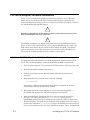
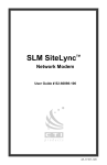
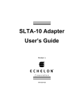
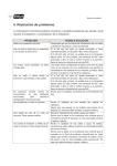
LONWORKS
®
PCLTA-20 PCI LonTalk
Adapter User’s Guide
®
Version 2
E
Corporation
078-0179-01B
Echelon, LON, LONWORKS, LonTalk, LonBuilder, NodeBuilder, LONMARK,
Neuron, LonManager, 3120, and 3150 are trademarks of Echelon
Corporation registered in the United States and other countries.
Other brand and product names are trademarks or registered
trademarks of their respective holders.
Neuron Chips, PC LonTalk Adapters, SMX Transceivers, and other OEM
Products were not designed for use in equipment or systems which
involve danger to human health or safety or a risk of property damage
and Echelon assumes no responsibility or liability for use of these
products in such applications.
Parts manufactured by vendors other than Echelon and referenced in
this document have been described for illustrative purposes only, and
may not have been tested by Echelon. It is the responsibility of the
customer to determine the suitability of these parts for each
application.
ECHELON MAKES AND YOU RECEIVE NO WARRANTIES OR CONDITIONS,
EXPRESS, IMPLIED, STATUTORY OR IN ANY COMMUNICATION WITH YOU,
AND ECHELON SPECIFICALLY DISCLAIMS ANY IMPLIED WARRANTY OF
MERCHANTABILITY OR FITNESS FOR A PARTICULAR PURPOSE.
No part of this publication may be reproduced, stored in a retrieval
system, or transmitted, in any form or by any means, electronic,
mechanical, photocopying, recording, or otherwise, without the prior
written permission of Echelon Corporation.
Printed in the United States of America.
Copyright ©1999 by Echelon Corporation.
Echelon Corporation
4015 Miranda Avenue
Palo Alto, CA 94304, USA
www.echelon.com
FCC NOTICE (for USA only)
Federal Communications Commission Radio Frequency Interference Statement
Warning: This equipment has been tested and found to comply with the limits for
a Class B digital device, pursuant to part 15 of the FCC Rules. These limits are
designed to provide reasonable protection against harmful interference in a
residential installation. This equipment generates, uses and can radiate radio
frequency energy and, if not installed and used in accordance with the
instructions, may cause harmful interference to radio communications. However,
there is no guarantee that interference will not occur in a particular installation.
If this equipment does cause harmful interference to radio or television reception,
which can be determined by turning the equipment off and on, the user is
encouraged to try to correct the interference by one or more of the following
measures:
•
Reorient or relocate the receiving antenna.
•
Increase the separation between the equipment and receiver.
•
Connect the equipment into an outlet on a circuit different from that to which
the receiver is connected.
•
Consult the dealer or an experience radio/TV technician for help.
Changes or modifications not expressly approved by Echelon Corporation could
void the user’s authority to operate the equipment.
Safety
UL
Listed Accessory, per UL-1950
c-UL (CSA)
Certified, per C22.2 no. 950
CANADIAN DOC NOTICE
This digital apparatus does not exceed the Class B limits for radio noise
emissions from digital apparatus set out in the Radio Interference Regulations of
the Canadian Department of Communications.
Le présent appareil numérique n’émet pas de bruits radioélectriques dépassant
les limites applicables aux appareils numériques de la classe B prescrites dans le
réglement sur la brouillage radioélectrique édicté par le Ministére des
Communications du Canada.
Contents
1 PCLTA-20 Adapter Introduction
Introduction
Audience
Content
Related Documentation
2 Installing the PCLTA-20 Adapter
PCLTA-20 Adapter Software Installation
Windows® 95/98 Software Installation Procedure
Windows NT® Software Installation Procedure
Software Installation Results
Windows 95/98 Software Removal Procedure
Windows NT Software Removal Procedure
Windows 95/98 Virtual-Mode DOS Driver Installation Results
Windows NT Virtual-Mode DOS Driver Installation Results
PCLTA-20 Adapter Hardware Installation
ESD Warning
Troubleshooting
Installing the PCLTA-20 Adapter Before Software Installation
System Resources
Solving IRQ and I/O Conflicts under Windows 95/98
Common Resource Problems under Windows 95/98
Solving Conflicts under Windows NT
Software Compatibility
Device Name Aliasing under Windows 95/98
LonManager® Protocol Analyzer Compatibility
PCC-10 and PCLTA-10 Compatibility
WLDV Versions (Windows 95/98 only)
Plug ‘n Play Issues Under Windows NT
Automatic Flush Cancel Issues
3 Configuring and Testing the PCLTA-20 Adapter
PCLTA-20 Configuration
PCLTA-20 Initialization
Device Specific Settings
Device Selected
Automatic Flush Cancel
NI Application
PCLTA-20 Adapter User's Guide
1-1
1-2
1-3
1-3
1-3
2-1
2-2
2-2
2-3
2-5
2-5
2-5
2-6
2-6
2-7
2-7
2-7
2-8
2-8
2-9
2-9
2-10
2-10
2-10
2-11
2-11
2-11
2-11
2-12
3-1
3-2
3-2
3-3
3-3
3-3
3-3
iii
Transceiver…
Diagnostics…
General Settings
System Image Path
Layer2 and Layer6 Buffering
Enable PC Card Reset
PCLTA-20 Diagnostics
Driver Status
Diagnostic Commands
Test
Comm
Service
Restart
Reset
3-4
3-5
3-5
3-5
3-5
3-5
3-6
3-6
3-7
3-7
3-8
3-9
3-9
3-9
4 Developing with the PCLTA-20 Adapter
4-1
Initializing the PCLTA-20 Adapter
Canceling the Flush State
Configuring the PCLTA-20 Adapter with a Network Address
Installing a PCLTA-20 Adapter on a LONWORKS Network
Installing with an LNS Tool
Installing with the LonBuilder® Tool
Installing with Other Network Tools
Rebooting a PCLTA-20 Adapter
Default Configuration
5 Electrical and Mechanical Interfaces
5-1
PCLTA-20 Adapter Board Layout
P1 and P2 PCI Bus Connector
Network Connector
Mechanical Considerations
5-2
5-3
5-3
5-4
6 References
6-1
Reference Documentation
6-2
CE Declaration of Conformity
iv
4-2
4-2
4-2
4-3
4-3
4-3
4-4
4-5
4-5
Echelon
1
PCLTA-20 Adapter Introduction
Echelon’s PCLTA-20 PCI LonTalk® Adapter (Models 74401, 74402,
74403, 74404, and 74405) is a high-performance LONWORKS® interface
for desktop, and embedded personal computers equipped with a 32-bit
PCI interface and a compatible operating system. Designed for use in
LONWORKS control networks that require a PC to monitor, manage, or
diagnose the network, the PCLTA-20 adapter is ideal for industrial
control, building automation, and process control applications. The
PCLTA-20 adapter features support for a wide range of transceivers,
downloadable memory, a network management interface, and Plug n’
Play capability with Microsoft® Windows 95, 98 and NT operating
systems.
The four versions of the PCLTA-20 with integral twisted pair
transceivers support the TP/FT-10 (model 74401), TP/XF-78 (model
74402), TP/XF-1250 (model 74403), and TP-RS485 (model 74404)
channels, respectively. The model 74405 PCLTA-20 supports SMX
transceivers, and may therefore be used on a wide range of channels,
including Echelon’s PL-10, PL-20, and PL-30 power line channels.
The PCLTA-20 adapter provides both network services interface (NSI)
functionality for use with LNS-compliant tools, and network interface
functionality for use with older LonManager API-based tools.
Echelon's PCLTA-20 is for use only with IBM AT or compatible UL
listed personal computers that have Installation Instructions detailing
user installation of card cage accessories.
PCLTA-20 Adapter User’s Guide
1-1
Introduction
The PCLTA-20 adapter provides any host processor equipped with a 32-bit PCI
interface and compatible operating system with access to a LONWORKS network.
Installation software for the PCLTA-20 adapter is provided in the Connectivity
Starter Kit Model 58030-01 (which must be purchased separately), and provides a
software-based control panel and a software driver for Microsoft Windows 95, 98, or
NT operating systems. Installation software also is available on Echelon’s web site at
www.echelon.com/support. The control panel provides a convenient means of
setting and modifying installation parameters, as well as displaying error messages.
The adapter supports Windows 95 and 98 Plug n’ Play operation, simplifying
installation and use.
The PCLTA-20 adapter operates at 10MHz and, depending on the model selected,
includes either an integral twisted pair transceiver or an SMX transceiver interface.
For models with an integral twisted pair transceiver, the network connection is made
via a removable screw terminal block.
As shown in figure 1.1 below, the LONWORKS Network Services (LNS) architecture
allows any number of installation, maintenance, monitoring and control devices to
exist in a system and to adapt to network configuration changes automatically. That
is, it allows users to reconfigure the system from any user interface device anywhere
on the network and ensures that all monitoring and control stations are always upto-date with respect to the system’s configuration. When used with the appropriate
software, the network services interface (NSI) functionality of the PCLTA-20 adapter
allows the attached host to tap into the LNS infrastructure as a client or server
application.
Control devices (sensors,
actuators, motors, etc.)
Supervisor
Maintenance
Tool
Control Panel
Operator
Console
Service
Technician
Tool
Gateway
Foreign System
Remote
Monitoring
Tool
Remote
Console
Figure 1.1 Multiple System Level Tools based on LNS
The adapter also permits the host PC to act as an application node, running
application-specific programs while the adapter handles lower layer functions such as
media access control, collision avoidance, message validation, authentication, and
1-2
Introduction
priority processing. Separating the application layer of the LonTalk protocol from
the lower layers makes the PCLTA-20 adapter independent of its host application.
The host application, including its network variables, can be changed at any time
without modifying the adapter. The PCLTA-20 adapter combined with the host PC
can also be used with nodes that require more processing power, memory,
input/output capability, or network variable connections than are provided by the
Neuron® Chip alone.
Firmware for the adapter is downloaded from the host PC. This allows the adapter
to be updated as new versions of the software and firmware are released, without
modifying or physically accessing the PCLTA-20 adapter. This feature extends the
useful service life of the adapter, and minimizes the cost and time associated with
software and firmware updates. The adapter is provided with 32K bytes of off-chip
RAM for use as network and application buffers. See Chapter 4 for a complete list of
buffer configurations,
Audience
This manual is intended for developers and end users of LONWORKS systems using
the PCLTA-20 adapter.
Content
This manual provides detailed technical specifications on the electrical and
mechanical interfaces and operating environment characteristics for the PCLTA-20
adapter.
This document has a list of references in Chapter 6. Whenever a reference document
is addressed, a superscript number corresponding to the reference has been placed in
the text, e.g., FTT-10A Free Topology Transceiver User's Guide1. Whenever a specific
chapter or section within a reference has been referred to, the reference is enclosed in
brackets and the chapter is addressed by number, e.g., Reference [1], Chapter 4.
Related Documentation
The following Echelon publications are suggested for additional information:
•
Neuron Chip Data Book as published by Motorola, Toshiba, and/or Cypress
•
LONWORKS® SMX™ Transceiver Installation Instructions 078-0145-01 version D or later
•
LONWORKS FTT-10A Free Topology Transceiver User’s Guide (078-0156-01)
•
LONWORKS Junction Box and Wiring Guidelines Application Notee (005-0023-01)
•
LONWORKS TPT Twisted Pair Transceiver Module User’s Guide (078-0025-01)
•
LNS Host API Programmer’s Guide (078-0163-01A)
•
LCA Object and Data Server Programmer’s Guide (078-0162-01A)
PCLTA-20 Adapter User’s Guide
1-3
1-4
Introduction
2
Installing the PCLTA-20 Adapter
This chapter describes the procedures for installing the PCLTA-20
adapter in a PC or embedded host with a compatible operating system.
PCLTA-20 Adapter User’s Guide
2-1
PCLTA-20 Adapter Software Installation
There are two versions of the PCLTA-20 installation software, one for Windows
95/98, and one for Windows NT. Each version installs the files required by the
associated Windows operating system to recognize the PCLTA-20 adapter, as well as
the downloadable NSI and MIP images.
!
Therefore, installation of the software must occur before insertion of the
PCLTA-20 adapter into a PC’s PCI slot.
!
The PCLTA-20 software can support DOS applications via the DOS virtual device
driver, however, this requires that the PC be running Windows 95, 98, or NT – the
DOS virtual device driver does not work on PCs running only DOS. The default
mode of operation is as an LNS network services interface (NSI); the MIP mode
image may be enabled through the driver software control panel.
Windows 95/98 Software Installation Procedure
To install the PCLTA-20 software on a Windows 95/98 PC, follow the instructions
below. The PCLTA-20 software cannot be installed from DOS or a DOS shell.
1. Close all open programs. Do not insert the PCLTA-20 into a PCI slot at this time.
2. Insert the installation diskette into the PC.
3. Click the Start button on the Windows 95/98 task bar and select the run
command.
4. When prompted for a program name, enter the following:
a:\SETUP.EXE
If necessary, replace a: with the drive letter which corresponds to the drive
containing the PCLTA-20 installation diskette.
5. When prompted with a list of languages, click on the desired language. A
checkmark will appear to the left of the language to be installed.
6. When prompted for a destination directory, enter the desired installation
directory. By default this directory is c:\lonworks, unless previous
LONWORKS products have been installed and registered a different path in the
Windows Registry. The path may be modified using the Browse button; however,
if a directory other than c:\lonworks is chosen, the PCLTA-20 images path will
have to be specified to enable use of the PCLTA-20 adapter. This is accomplished
2-2
Installing the PCLTA-20 Adapter
during PCLTA-20 Configuration. See Chapter 3, Configuring and Testing the
PCLTA-20 Adapter.
7. When the 16-bit Application Support prompt appears, select “Yes” to enable the
use of 16-bit applications with the PCLTA-20 adapter. This causes the
installation program to add references to the DOS CONFIG.SYS file for the “stub”
device drivers named PCCLON1 and PCCLON2. This allows existing 16-bit
applications to recognize these device names and use the PCLTA-20 adapter as a
network interface. If more than two PCLTA-20 adapters are installed in the PC,
additional stub drivers can be created manually. To do so, add the following lines
to the CONFIG.SYS file:
DEVICE=C:\LONWORKS\BIN\LDVSTUB.SYS /D:PCCLON3
DEVICE=C:\LONWORKS\BIN\LDVSTUB.SYS /D:PCCLON4
There is a limit of six (6) PCLTA-20 adapters in a single PC.
Once the driver is installed and active, existing 16-bit Windows applications can
access the PCLTA-20 adapter using the ldv_open(), ldv_close(),
ldv_read(), and ldv_write() functions provided by the WLDV.DLL file.
The installation software installs a new WLDV.DLL file in \WINDOWS\SYSTEM,
replacing any pre-existing versions of the file. The updated WLDV.DLL is fully
backward-compatible with previous versions.
8. If the installation software discovers the SYSTEM.INI entry that loads the PCIbus driver, ECHLMPA.386, it will comment out the entry and display the message,
“SETUP has modified your SYSTEM.INI file by removing the following entry:
device=echlmpa.386.” It is not possible to use the ISA-bus protocol analyzer card
and the PCLTA-20 card on the same PC.
9. The installation software for the Windows 95/98 version will issue a prompt to
add a DOS virtual-mode device driver file named LDVVDD.SYS to the DOS
CONFIG.SYS file to support DOS applications calling LON1. This will allow DOS
applications to be used in a Windows 95/98 DOS shell/window. For more
information see Virtual-Mode DOS Driver later in this chapter. The following
line is added to the CONFIG.SYS file:
DEVICE=C:\LONWORKS\BIN\LDVVDD.SYS /D1
10. Software installation is complete. At the prompt to restart the computer, remove
the PCLTA-20 installation diskette and shut down the computer. Next insert the
PCLTA-20 into a PCI slot and turn the computer back on.
Windows NT Software Installation Procedure
To install the PCLTA-20 software on a Windows NT PC, follow the instructions
below. The PCLTA-20 software cannot be installed from DOS or a DOS shell.
PCLTA-20 Adapter User’s Guide
2-3
.
!
Only install the PCLTA-20 adapter after the software has been installed.
!
1. Close all open programs.
2. Insert the installation diskette into the PC.
3. In Windows NT 4.0 or later, click the Start button on the Windows NT task bar
and select the run command. In Windows NT 3.51 select “Run...” from the file
menu of the Program Manager.
4. When prompted for a program name, enter the following:
a:\SETUP.EXE
If necessary, replace a: with the drive letter which corresponds to the drive
containing the PCLTA-20 installation diskette.
5. When prompted with a list of languages, click on the desired language. A
checkmark will appear to the left of the language to be installed.
6. When prompted for a destination directory, enter the desired installation
directory. By default this directory is c:\lonworks, unless previous
LONWORKS products have been installed and registered a different path in the
Windows Registry. The path may be modified using the Browse button; however,
if a directory other than c:\lonworks is chosen, the PCLTA-20 images path will
have to be specified to enable use of the PCLTA-20 adapter. This is accomplished
during PCLTA-20 Configuration. See Chapter 3, Configuring and Testing the
PCLTA-20 Adapter.
7. There is a limit of six (6) PCLTA-20 adapters in a single PC.
Once the driver is installed and active, existing 16-bit Windows applications can
access the PCLTA-20 adapter using the ldv_open(), ldv_close(),
ldv_read(), and ldv_write() functions provided by the PCLTDOS.SYS file.
8. The installation software for the Windows NT version will issue a prompt to add
a DOS virtual-mode device driver file to the DOS CONFIG.NT file to support DOS
applications calling LON1. This will allow DOS applications to be used in a
Windows NT DOS shell/window. For more information see Virtual-Mode DOS
Driver later in this chapter. The following line is added to the CONFIG.NT file:
DEVICE=%SYSTEMROOT%\SYSTEM32\PCLTDOS.SYS /D1
The argument /D1 names this DOS device as LON1.
2-4
Installing the PCLTA-20 Adapter
9. Software installation is complete. At the prompt to restart the computer, remove
the PCLTA-20 installation diskette, turn off power, install the PCLTA-20, and
then reboot the computer.
Software Installation Results
The installation software for the PCLTA-20 adapter loads a selection of new files and
updated versions of existing files to different locations on the PC’s hard drive. The
function and location of these files can be found in the on-line help file.
Windows 95/98 Software Removal Procedure
To remove the PCLTA-20 software, use the Uninstall control panel, as follows:
1. Choose the Add/Remove Programs icon from the Control Panel folder.
2. Select “LonWorks® PCLTA-10/20/PCC-10 for Windows® 95/98” from the list
under the Install/Uninstall tab.
3. Click the “Add/Remove...” button.
4. Confirm file deletion at the prompt. Most of the PCLTA-20 software will be
removed automatically.
5. If necessary, edit the CONFIG.SYS file to remove any references to the stub
driver.
Windows NT Software Removal Procedure
To remove the PCLTA-20 software under Windows NT 4.0 or later, use the Uninstall
control panel, as follows:
1. Choose the Add/Remove programs icon from the Control Panel folder.
2. Select “LonWorks® PCLTA-10/20/PCC-10 for Windows® NT” from the list under
the Install/Uninstall tab.
3. Click the “Add/Remove...” button.
4. Confirm the deletion at the prompt. Most of the PCLTA-20 software will be
removed automatically.
5. If necessary, edit the CONFIG.NT file to remove any references to the
PCLTADOS.SYS driver.
To remove the PCLTA-20 software under Windows NT 3.51, remove all files that
were created during installation. See Windows NT Installation Results in the help
file for a list of these files and their locations.
PCLTA-20 Adapter User’s Guide
2-5
Windows 95/98 Virtual-Mode DOS Driver Installation Results
The Windows 95 PCLTA-20 adapter installation software will prompt the installer to
automatically add the virtual-mode DOS driver. This driver is small in size, and
allows a DOS session under Windows to have access to the PCLTA-20 through the
device driver running as a part of Windows. The driver will not function unless a
Windows session is running and the PCLTA-20 device driver is installed.
The following line will be added to the CONFIG.SYS file:
DEVICE=<directory of file>\LDVVDD.SYS /Dn /Ln
/Dn
where (n) is 1-9. This defines LON1-LON9 and corresponds to devices 1-9
as determined by the PCLTA-20 adapter device driver under Windows.
This parameter is optional; the default is “1”.
/Ln
where (n) is 1-9. This defines the logical device 1-9 as determined by the
PCLTA-20 adapter device driver under Windows. This parameter is
optional, the default is the value determined by the /Dn parameter. This
allows overriding the actual device accessed from being based on the /Dn
parameter.
For example, using /D9 /L1 will in fact create a DOS driver named LON9 that will
actually access the 1st PCLTA-20 in the system. Without the /L1 parameter you
would access the 9th device, as determined by the /D9 option. These options are
typically needed when more than one LonWorks network interface is present in the
system.
Windows NT Virtual-Mode DOS Driver Installation Results
The Windows NT PCLTA-20 adapter installation software will prompt the installer
to automatically add the virtual-mode DOS driver. This driver is small in size, and
allows a DOS session under Windows to have access to the PCLTA-20 through the
device driver running as a part of Windows. The driver will not function unless a
Windows session is running and the PCLTA-20 device driver is installed.
The following line will be added to the system32 folder under the WinNT system
directory:
DEVICE=<directory of file>\PCLTDOS.SYS /Dn
/Dn
where (n) is 1-9. This defines LON1-LON9 and corresponds to devices 1-9
as determined by the PCLTA-20 adapter device driver under Windows.
The following is an example of the line that would be added to the CONFIG.NT file:
DEVICE=C:\LONWORKS\BIN\PCLTDOS.SYS /D1
2-6
Installing the PCLTA-20 Adapter
PCLTA-20 Adapter Hardware Installation
!
ESD Warning
This product contains devices which are sensitive to static electricity. Before
installing or removing the PCLTA-20 adapter or the network cables,
discharge any static electricity which may have accumulated to earth ground.
1. Turn off the PC and remove the power cord.
2. Open the PC case and locate an empty 32-bit PCI slot. Remove the
corresponding blank panel from the rear of the PC. Set aside the screw.
3. Insert the PCLTA-20 adapter into the slot, ensuring that the edge connectors are
fully mated and the slot in the rear panel mounting lug of the PCLTA-20 adapter
is aligned with the threaded hole in the PC chassis.
If using a model 74405 PCLTA-20, insert the SMX transceiver in accordance with
the manufacturer’s instructions before installing the PCLTA-20—see the document
LONWORKS® SMX™ Transceiver Installation Instructions document 078-0145-01
version D or later if using an Echelon SMX transceiver. Note that the height of
the PLM-10, PLM-2X, and PLM-30 Power Line SMX Transceivers is such
that two (2) PCI slots must be allocated for a PCLTA-20 equipped with a
PLM, even though the adapter will be plugged into only one slot.
4. Replace the screw to hold the PCLTA-20 adapter firmly in place.
5. Reinsert the power cord and then restart the PC. A “New Hardware Found”
window will be displayed briefly when the operating system recognizes
the PCLTA-20 adapter.
Troubleshooting
As a “plug and play” type device, the PCLTA-20 adapter should operate as desired
following completion of the installation process. If the adapter does not function
correctly, the most likely causes are system resource constraints or software
incompatibilities. These problems are described in detail in the following sections.
PCLTA-20 Adapter User’s Guide
2-7
Installing the PCLTA-20 Adapter Before Software Installation
The following section applies to Windows 95/98 only.
If the PCLTA-20 adapter was inserted into the PC prior to PCLTA-20 software
installation, the Windows operating system will be unable to associate a device driver
with the adapter. When Windows 95/98 starts up, a “New Hardware Found” window
will appear. Click the Cancel button, then install the PCLTA-20 software as
described above.
If the option “Do not install a driver (Windows will not prompt you again)” was
inadvertently selected, the operating system will mark the PCLTA-20 adapter as an
unknown device. As a result, the adapter will not function even if the PCLTA-20
software is installed. To correct this problem, “remove” the device using the
following steps:
1. Open the System control panel and select the tab labeled “Device Manager.”
2. Double-click the “Other devices” icon.
3. Select “PCLTA-20” device and click the Remove button.
4. Install the PCLTA-20 software and reboot the PC.
System Resources
Each PCLTA-20 adapter requires sixteen contiguous bytes of I/O address space
starting on a modulo-4 based address, i.e., an address evenly divisible by 4. A
dedicated interrupt request (IRQ) is also required for each PCLTA-20 adapter used.
Solving IRQ and I/O Conflicts under Windows 95/98
I/O resource problems are rare under Windows 95/98 for the PCLTA-20 adapter since
the adapter can handle a wide range of I/O settings. However, IRQ resource
problems may occur more often in “multimedia” computers which may have very few
spare IRQs. The Windows 95/98 operating system handles most allocations of IRQs,
but there are some instances where the operating system cannot properly allocate
interrupt requests.
When the Windows 95/98 Device Manager does not locate a free IRQ for a newly
inserted PCLTA-20 adapter, it will not assign an IRQ to the adapter. As a result,
there may be no indication to the user that a problem has occurred, since no true
resource “conflict” has occurred. This is a consequence of the PCLTA-20 adapter’s
ability to be assigned any of the system’s 16 IRQs.
IRQ usage in the system can be determined by opening the System icon in the
Control Panel window. The tab labeled “Device Manager” allows viewing of devices
by type or connection.
The PCLTA-20 LONWORKS Network Interface device icon is found under the
“LonWorks Interface” device type. If there is a problem with the adapter, there will
be a red circle with an exclamation point next to its icon.
2-8
Installing the PCLTA-20 Adapter
IRQ resource problems may generally be resolved by disabling another device in the
system. More information can be found in the Hardware Conflict troubleshooting
portion of the Windows 95/98 on-line Help file.
Access the hardware conflict troubleshooter through the procedure outlined below:
1. Open the Windows 95/98 on-line help by clicking the Windows Start button
and selecting “Help.”
2. In the Help Topics window, choose the Contents tab, or from another Help
window, choose the Contents button.
3. Double click the Troubleshooting topic, and then select the help topic, “If You
Have A Hardware Conflict.”
Extensive trouble-shooting documentation can be found in the Microsoft Windows
95/98 Resource Kit Help File. This help file is part of the Windows 95/98 Resource
Kit, which is available from Microsoft.
If a DOS real-mode driver is in use for a specific device which is installed in the PC,
Windows 95/98 may not know about that device’s resource requirements. Unlike
Windows driver conflicts, this problem is difficult to diagnose.
There are rare I/O conflict situations of which the Device Manager may be unaware.
Such a conflict may occur when an I/O resource is not properly specified for a device,
and a new driver overlays onto the true I/O space of that device. In the event of such
a conflict, it may become necessary to manually reserve I/O or IRQ resources using
the Device Manager. This process is described in the Windows 95/98 on-line Help.
Once these resources have been reserved, the Device Manager will recognize and
attempt to resolve any resource conflicts between the DOS driver and any Windows
drivers. If a conflict still occurs, it will be “visible,” and may be resolved as described
in Solving IRQ and I/O Conflicts under Windows 95/98 earlier in this chapter.
If a device resource requirement is “hardwired” into the PC (i.e., configured by a
jumper or not modifiable from the system BIOS) then there is little that the Windows
95/98 operating system can do to free the resources.
Common Resource Problems under Windows 95/98
The following situations produce an additional drain on system resources that may
be hard to manage. Conflicts arising from these situations can generally be resolved
by selectively disabling devices to free up the required resources.
•
COM ports that may not have a connector, but are consuming resources and
cannot be disabled through the BIOS
•
Unused IDE controllers that can not be disabled through the BIOS
•
Unused/nonexistent PS/2 mouse ports
•
Sound cards that support both 8-bit and 16-bit compatibility modes,
consuming two IRQs
An additional problem often associated with sound cards is the improper reporting of
I/O resource usage. This problem may be recognized by examining a device’s I/O
address allocation for unusual one-byte assignments (since devices typically use
more). For example, if a device’s stated I/O range is 0x201-0x201 but its actual range
is 0x201-0x204, a conflict will occur if the PCLTA-20 adapter is assigned an I/O range
PCLTA-20 Adapter User’s Guide
2-9
of 0x204-0x207. If this problem is suspected, manually move the PCLTA-20
adapter’s I/O range to a safer location to prevent I/O overlap.
Solving Conflicts under Windows NT
The device driver PNPLON.SYS works with the Windows NT operating system to
locate PCLTA-20 cards. The driver is completely Plug n’ Play, and because the
device is a PCI card, the system BIOS will determine a useable I/O port and IRQ
setting. There is no user-configurable resources setting from the Windows NT
operating system.
If more control is required over the choice of IRQs used for the PCLTA-20, there is an
optional system setting that can be used. The Preference button on the LONWORKS
Plug ‘n Play control panel brings up a self-explanatory dialog that allows the setting
of the preferred and alternative IRQ list.
The Preference button also allows a choice of the numeric base for the device naming
convention, i.e, the value of x in LONx. By default this will start at “LON1”. This
could create a conflict if another device driver is also trying to create a device named
“LON1” (such as a PCNSS/PCNSI driver). In this case choose another value.
If other values are chosen for the device naming convention then you may want to
assure that the DOS driver defined in your CONFIG.NT file reflects this setting. It is
this DOS driver in the CONFIG.NT file that defines the device name used by 16-bit
Windows applications running under NT, so such an application will refer to devices
named “LON1”, “LON2”, and so on.
The first place to go for information if problems arise should be the Event Log under
System Events.
Software Compatibility
The PCLTA-20 adapter software is designed to be compatible with LONWORKS-based
software. However, the following issues may arise when using the PCLTA-20
adapter with some software.
Device Name Aliasing under Windows 95/98
The PCLTA-20 adapter should operate with most third party LONWORKS-based
software. However, some 16-bit Windows applications which use the services of
Echelon’s WLDV dynamic link library are limited in the device names that can be
selected. For example, only the names “LON1” through “LON9” may be available,
preventing the use of a PCLTA-20 adapter. This problem can be corrected through
the use of device name aliasing. To create a device alias, follow these instructions:
2-10
Installing the PCLTA-20 Adapter
1. Open the file named ECHELON.INI, which should reside in the WINDOWS
directory. If this file does not exist, then create one with a text editor.
2. Create a driver alias section in the file, by adding the following line:
[DRIVERALIAS]
3. On the following line, add the driver alias:
aliasname=devicename
where aliasname is the device name accessed by the software, such as “LON1”,
and devicename is the device to be used.
4. Add additional aliases, as necessary.
The following example creates a device alias that routes all service requests for
LON1 to the PCLTA-20 adapter PCCLON1.
[DRIVERALIAS]
LON1=PCCLON1
LonManager Protocol Analyzer Compatibility
The device driver for the PCLTA-20 adapter and the driver for the LonManager
Protocol Analyzer ISA-bus card share the same Windows VxD identifier. As a result,
both types of cards cannot run on a PC at the same time. So, the PCLTA-20
installation software will comment out the SYSTEM.INI entry that loads the ISA-bus
driver.
The LonManager Protocol Analyzer does not run under Windows NT.
PCC-10 and PCLTA-10 Compatibility
The LONWORKS Plug n’ Play control panel can only support one type of
downloadable-image network adapter at a time unless the system image files are
copied and renamed. PCC-10 cards, PCLTA-10 adapters, and PCLTA-20 adapters
may not be used or installed in the same PC unless the system image files are copied
and renamed.
WLDV Versions (Windows 95/98 only)
Older versions of Echelon’s WLDV.DLL file do not support the PCLTA-20 adapter. If
an older version (version 2.54 or earlier) of the file is inadvertently copied into the
WINDOWS\SYSTEM directory, the PCLTA-20 adapter will be unable to operate.
Should this occur, reinstall the PCLTA-20 software to update WLDV.DLL.
Under Windows NT, older versions of WLDV.DLL will still work via DPMI.
Plug ‘n Play Issues Under Windows NT
If both a PCLTA-20 and PCNSI are running and both devices have created
"\\.\Lon1.0" values for the "device" key then a named device conflict will occur. The
only option is to change the device name for the PCLTA-20. To do this, call up the
LONWORKS Plug ‘n Play control panel and press the Preferences button. This will
present a screen with which the name can be changed, e.g., 'LON2'. Reboot the PC.
PCLTA-20 Adapter User’s Guide
2-11
The PCLTA-20 will now be renamed LON2 and the named device conflict will be
resolved.
Under certain circumstances the LONWORKS Plug ‘n Play control panel diagnostics
functions states that the PCLTA-20 and driver are functioning; however, the
LonMaker for Windows Integration Tool or any other LNS-based tool do not work.
You will notice that when the network is open the tool indicates that it is unable to
communicate with the PCLTA-20 NSI. This is because the PCLTA-20 features a
downloadable firmware image and the LONWORKS Plug ‘n Play control panel must
be reconfigured to use the NSI. The "Ni Application" must read NSIPCLTA, and not
PCC10L7 or PCL10L7.
If, after pressing the TEST button after installation of a PCLTA-20, an **ErrorImage Load Failure” message is reported, then there is either an I/O conflict with the
PCLTA-20, or the adapter is broken. If there is an I/O conflict, then Windows NT is
not granting an unused I/O port to the PCLTA-20 driver. To rule out a broken
adapter, check the adapter using a Windows'95 configuration known to be reliable.
Automatic Flush Cancel Issues
If the PCLTA-20 card appears to install and test normally, but still will not
communicate on the network, check to be sure that the Automatic Flush Cancel
checkbox in the LONWORKS Plug ‘n Play control panel is still in its default (checked)
state. For more information, see the Automatic Flush Cancel section in chapter 3.
2-12
Installing the PCLTA-20 Adapter
3
Configuring and Testing the
PCLTA-20 Adapter
This chapter explains how to configure and test the PCLTA-20
adapter using the Control Panel installed in Chapter 2.
PCLTA-20 Adapter User's Guide
3-1
PCLTA-20 Configuration
PCLTA-20 configuration is accomplished by using the LONWORKS PCLTA-20
control panel. Open the control panel by selecting the “LonWorks® Plug ‘n Play”
icon in the Control Panel.
Figure 3.1 PCLTA-20 control panel and icon
The LONWORKS PCLTA-20 control panel is divided into three parts: a device
selection area, a general settings area, and a control section. The device selection
area contains configuration settings and diagnostic controls that are specific to an
individual PCLTA-20 adapter and its device driver. The general settings area
contains settings for all PCLTA-20 adapters used with the PC. The control section
contains buttons for accepting or canceling the changes made in the control panel, as
well as a Help button.
PCLTA-20 Initialization
In most cases, PCLTA-20 adapter initialization occurs automatically upon
installation of the adapter card and subsequent power-up of the computer. Manual
initialization will be required following software installation to a directory other
than c:\lonworks, or following the moving of the PCLTA-20 system images.
To manually initialize the PCLTA-20 adapter, verify that the control panel’s System
Image Path entry is correct, then click the Apply button.
An error will be reported if an attempt is made to view the transceiver type before
the PCLTA-20 adapter is initialized. Testing the card with the Diagnostics button,
as suggested by the error message, produces the diagnosis: “Image file not found.”
In this case, return to the control panel’s main dialog box and manually initialize the
PCLTA-20 adapter.
3-2
Configuring and Testing the PCLTA-20 Adapter
Device Specific Settings
The PCLTA-20-specific options consist of five separate controls (figure 3.2). These
controls are defined as follows:
Figure 3.2 PCLTA-20-specific Controls
Device Selected
Controls which PCLTA-20 adapter is selected for configuration. The PCCLON1 and
PCCLON2 drivers are installed by the installation software. If additional drivers
have been manually installed, PCCLON3 and/or PCCLON4 will also be available.
Automatic Flush Cancel
For non-NSI images, this function controls whether the device driver will
automatically force the network interface for the selected PCLTA-20 adapter to
leave the post-reset flush state whenever it is reset; an NSI does not and cannot
come up in the flush state. The post-reset flush state prevents any inbound or
outbound network traffic following a reset. If this box is not checked, it is up to
the client application to manage this state. If it is checked, the device driver
will automatically allow network traffic to resume. The default is checked.
NI Application
Controls the type of image or application to be used. A PCLTA-20 adapter can only
hold one image at a time. Loading a new image will replace the currently loaded
image. The choices for these images are determined by the image files (.NBI
extension) found in the system image path specified under General Settings. Some
of the possibilities include the following:
•
NSIPCLTA, the NSI image
•
PCC10L7, the basic network interface application image
•
NSIPCC, the Network Services Interface application image
Transceiver...
Opens the PCLTA-20 Transceiver dialog box (figure 3.3). Choosing this option will
retrieve the transceiver configuration of the selected PCLTA-20 adapter. If there is
PCLTA-20 Adapter User's Guide
3-3
no PCLTA-20 adapter currently installed in a PCI-bus slot, a message appears
stating that the operating system has removed, or has not loaded, the PCLTA-20
device driver.
Figure 3.3 PCLTA-20 Transceiver dialog box
The Transceiver selection box specifies the transceiver type for the selected PCLTA20 adapter. The default transceiver is an FT-10-compatible transceiver. Other
standard transceiver configurations, and a custom configuration, may be chosen
using this selection box. The Custom Properties controls are not accessible unless
the Custom transceiver type is selected: you cannot modify the transceiver type as it
is a product of the XID, however, if the XID is custom then you can modify the fields
using the Custom Properties dialog box. If an incorrect transceiver type error is
received while modifying the transceiver type, choose the Apply button, then proceed
to modify the transceiver type.
The Custom Properties area contains controls for entering custom transceiver
properties. The information in this area reflects the current configuration within
the PCLTA-20 adapter. It will not change until a transceiver is selected, and then
configured using the OK or Apply buttons.
When configuring a custom transceiver or adding custom parameters for a standard
transceiver, the values used in the Custom Properties Raw Data edit boxes must be
entered as hexadecimal values separated by dashes. Further explanation of Raw
Data values can be found in the LonBuilder® User’s Guide 2.
Diagnostics...
Opens the PCLTA-20 Diagnostics dialog box. For more information, see the section
on PCLTA-20 Diagnostics.
3-4
Configuring and Testing the PCLTA-20 Adapter
General Settings
The PCLTA-20-generic options consist of four controls (figure 3.4). These controls
are defined as follows:
Figure 3.4 PCLTA-20 generic controls
System Image Path
Specifies the full directory path for the PCLTA-20 system images. This path is set
by the PCLTA-20 Installation Software but may be modified by the user.
Layer2 and Layer6 Buffering
Controls the number of 4Kbyte operating system pages that are allocated for
message buffering within the driver. The Layer2 setting is reserved for future use
and should not be modified from the default of 20 pages. The Layer6 setting is used
for system images. The default setting of Layer6 Buffering is 6 pages. This value
should be appropriate for most applications; embedded systems may need to change
the number of buffering pages.
Enable PC Card Reset
This control is not used with the PCLTA-20 adapter. It is provided for owners of the
PCC-10 PC Card (PCMCIA card) and controls whether the hardware reset line is
enabled. The state of this checkbox is irrelevant to the operation of the PCLTA-20
adapter.
PCLTA-20 Diagnostics
A number of diagnostic and testing services are provided by the PCLTA-20 control
panel. Clicking the Diagnostics button in the main control panel window displays
the PCLTA-20 Diagnostics dialog box. This dialog box contains buttons for the
diagnostic commands and displays the version number and current status of the
PCLTA-20 device driver. If no PCLTA-20 adapter is installed in a PCI-bus slot, the
Diagnostics window will display “(no driver found)”.
PCLTA-20 Adapter User's Guide
3-5
LonWorks® PCC10/PCLTA10/PCLTA20 Device Driver
Version: 1.25
Card Type: PCLTA-20
Driver Status:
Number of Free LTA Output BuffersNon-Priority: 3, riority:
P
3
Loaded Image ize:S49408
Interrupt Count: 4
Figure 3.5 PCLTA-20 Diagnostics dialog box
Driver Status
The content of the device driver status is as follows:
•
Number of Free PCLTA-20 Output Buffers:
Non-Priority: the non-priority application output buffer count, as calculated
by the driver based on information retrieved from the PCLTA-20 adapter’s
non-volatile EEPROM.
Priority: the priority application output buffer count, as calculated by the
driver based on information retrieved from the PCLTA-20 adapter’s nonvolatile EEPROM.
•
Loaded Image Size: the size, in bytes, of the currently loaded PCLTA-20
system image. This may be zero if the PCLTA-20 adapter is in the initial
“boot” state.
•
Interrupt Count: the number of interrupts the driver has processed for this
device. This value is set to zero when the device is physically reset.
Diagnostic Commands
3-6
Configuring and Testing the PCLTA-20 Adapter
The diagnostic commands are invoked by selecting one of the buttons displayed in
figure 3.6. If a diagnostic command results in the “Image file not found” error
message, close the Diagnostics dialog box by selecting the OK button, then click the
Apply button in the PCLTA-20 control panel. This re-initializes the adapter and
allows use of the diagnostic commands.
Figure 3.6 Diagnostics dialog box commands
Test
The Test button retrieves status and error counts from the PCLTA-20 adapter. The
results of this message will be displayed in the format shown in figure 3.7.
PCLTA-20 Adapter User's Guide
3-7
-- Network Interface Node Status -CRC Errors:
[00000]
TX Timeouts:
[00000]
Lost (APP) Messages:
[00000]
Missed (NET) Messages:
[00000]
Node State:
Unconfigured
Most recent error:
0
Reset Cause:
External
Figure 3.7 Example Network Diagnostics Status Response
Comm
The Comm button verifies communications between the PCLTA-20 adapter and
another node on the network. When this function is chosen, a dialog will appear
asking for confirmation of this command, as follows:
This procedure will configure the Network Interface for a zerolength domain if it is not already configured. Do you want to
proceed?
Choosing OK causes the control panel to first check the network interface for the
configured state. If it is already in the configured state, it will not be modified
further. If it is not in the configured state it will install the network interface with a
zero-length domain on index 0, a subnet of 1, and a node ID of 126, and then change
its state to configured.
Once the node is in the configured state, the control panel enters the receive-ready
state and displays the following message while waiting for a service pin message
from another node on the network:
Now waiting for a service pin message.
Once the service pin is activated on the other node and a service pin message is
received, the control panel sends a request/response diagnostic message to the other
node using Neuron ID addressing. It will repeat this message, referred to as a
“ping,” once per second until either the ‘OK’ or the ‘Quit’ button is chosen (the Quit
button will appear in place of the Comm button).
This series of tests confirms that the device can be configured and can communicate
with a node on the network. The Comm function is intended to eliminate the
PCLTA-20 adapter, the card drivers, the network connection, the hardware of the
other node, and the topology configuration from the list of possible problem points or
points of failure during network troubleshooting. The Comm function test does not
eliminate the possibility that the wrong type of media has been used. Be sure that
the medium is suitable for use with the selected channel type. The Comm function
also does not eliminate the possibility of a missing or improper network termination.
3-8
Configuring and Testing the PCLTA-20 Adapter
The network wiring may work for this test but may fail if multiple nodes are
communicating. Be sure to verify that the proper termination is used when
troubleshooting communication problems.
The Comm feature is not designed to work across routers.
Service
The Service button will cause the PCLTA-20 adapter to broadcast a service pin
message on the network. The service pin message will not be sent if the adapter is
in the post-reset flush state (see Automatic Flush Cancel).
Restart
The Restart button clears the adapter’s Neuron Chip image and places the device
into the “boot” state. This is the device state found following a re-boot of the
Windows operating system. When this function is chosen a dialog box will appear
asking for confirmation of this command.
Reset
The Reset button causes a reset of the adapter’s Neuron Chip, but does not clear its
system image.
PCLTA-20 Adapter User's Guide
3-9
3-10
Configuring and Testing the PCLTA-20 Adapter
4
Developing with the PCLTA-20
Adapter
This chapter provides an overview of how to develop and use host
software with the PCLTA-20 adapter.
PCLTA-20 Adapter User’s Guide
4-1
Initializing the PCLTA-20 Adapter
Once a PCLTA-20 adapter and PC are powered, the host application must initialize
the PCLTA-20 adapter. If you are using a LonManager or LNS software product, you
may skip to the next section.
When a PCLTA-20 adapter is initially powered, it disables network communications
by entering the FLUSH, unconfigured state. The FLUSH state prevents the adapter
from responding to network management messages before the host application has
initialized the adapter. The unconfigured state prevents the PCLTA-20 adapter from
responding to application messages before the node has been installed in a network.
The host application will not be able to send or receive application messages until
after it cancels the FLUSH state and the PCLTA-20 adapter leaves the unconfigured
state.
To initialize a PCLTA-20 adapter, follow the steps below (these steps are described in
more detail in the LONWORKS Host Application Programmer's Guide4).
Canceling the Flush State
By default, the PCLTA-20 adapter automatically leaves the FLUSH state upon reset.
If the Automatic Flush Cancel option has been disabled in the PCLTA-20
Control Panel, the flush cancel must be performed by the host application.
If the host application attempts to send a message while the PCLTA-20 adapter is in
the FLUSH state, the adapter will return a failed response for acknowledged messages
and a success response for unacknowledged messages. The message will not be sent
in either case.
If the host application attempts to send a message while the adapter is in the
NORMAL, unconfigured state, the PCLTA-20 adapter will always return a success
response even though the message was not sent.
To cancel the FLUSH state, follow these steps:
1. Reset the PCLTA-20 adapter from the host application by sending the niRESET
command. If installed correctly, the PCLTA-20 adapter will respond with an
uplink niRESET message upon completion of the reset. The first message from
an adapter after the network driver has been opened will also be an uplink
niRESET command informing the host that the PCLTA-20 adapter has been
released from reset.
2. Cancel the FLUSH state in the PCLTA-20 adapter. This is done automatically by
the device driver after an open command or uplink niRESET depending on the
setting for FLUSH state in the Plug ‘n Play control panel. The FLUSH state can be
manually canceled by sending the niFLUSH_CANCEL message.
Configuring the PCLTA-20 Adapter with a Network Address
The PCLTA-20 adapter leaves the unconfigured state when it is installed in a
network and is assigned an address in one or two domains on that network. There
are two ways this can happen. If the PCLTA-20 adapter is used as a network
interface for a network tool, then the tool’s application may configure the network
4-2
Using the PCLTA-20 Adapter
interface. In this case the PC running the network application sends a local message
to the PCLTA-20 adapter to change its state to configured.
Alternately, the PCLTA-20 adapter may be installed in a network by some other
network tool or a Network Services Server (NSS). In this case, the network tool or
server sends a message to the PCLTA-20 adapter across the network to change its
state and to assign it an address.
Once the PCLTA-20 adapter enters the configured state, it retains both the
configured state and its address assignment across power-cycles, because that
information is stored in the internal EEPROM.
To configure the PCLTA-20 adapter follow these steps:
1. Install the PCLTA-20 adapter in one or two domains using the Update Domain
network management message. This may be done by a network tool across the
network, or may be done directly by the host application by sending the Update
Domain message as a local network management command.
2. Change the state of the network interface to configured. This may be done by a
network tool across the network, or may be done directly by the host application
by sending the Set Node Mode network management message.
For LNS applications with a local NSS, both steps are performed by the LNS API
NsInit() function, or the LCA System object’s Open method. For remote LNS
applications, these steps are performed by the LNS API NsInit() and
NsIssueAddMyNsi() functions, or by setting the ActiveRemoteNI property of the
LCA Object Server OCX.
For other applications, both steps are performed locally using the LonManager API
lxt_open() function, while remote configuration is accomplished using an appropriate
network tool.
Installing a PCLTA-20 Adapter on a LONWORKS Network
A PCLTA-20 adapter with a host that is attached to a network appears as a standard
LONWORKS node to other nodes on the same network. The PCLTA-20-based node is
logically installed on a network using pre-installation, self-installation, or field
installation with a network tool. These installation scenarios are described in the
LONWORKS Installation Overview engineering bulletin (number 005-0006-01).
Unique installation requirements of host applications are described in Chapter 3 of
the LONWORKS Host Application Programmer's Guide4.
Installing with an LNS Tool
When a PCLTA-20 adapter is used as a Network Services Interface (NSI) for a PC
running an LNS tool like the LonMaker for Windows Integration Tool, installation of
the PCLTA-20 is handled automatically when the LNS tool is initialized.
Installing with the LonBuilder Tool
If the PCLTA-20 adapter is not used as an NSI, i.e., it is used in the MIP mode, it
can be installed on a development network using the LonBuilder Network Manager.
PCLTA-20 Adapter User’s Guide
4-3
Chapter 6 of the LonBuilder User’s Guide2 describes how to define and install nodes
in a development network using the LonBuilder Network Manager. A prerequisite to
creating application node target hardware and node specifications is to define the
channel that will be included in the network as defined under Defining Channels in
Chapter 10 of the LonBuilder User's Guide2. Be sure to correctly set the minimum
clock rate field. If this field is set incorrectly, excessive collisions will occur. If a
channel includes nodes with a slower clock rate or less accurate clocks, the channel
definition must meet this lowest common denominator for optimal performance.
Additionally, if the priority configured for the PCLTA-20 adapter is different from
the default, then the Number of Priority Slots needs to be set correctly.
Create a hardware properties definition for a custom node to represent the
PCLTA-20-based node. Set the input clock rate to 10MHz and then create a
hardware definition for the custom node specifying these hardware properties. If an
incorrect clock rate is specified in the hardware properties, the PCLTA-20 adapter
may be rendered unusable and will need to be reset. This may occur, for example, if
the default_hw_props option is specified. To install the PCLTA-20 adapter in a
LonBuilder network using the service pin, open the network driver (for example, by
using the installed Control Panel) and use the command to send a service pin
message.
When installing the PCLTA-20-based node, the channel definition must match the
transceiver built into the PCLTA-20 adapter (model 74401, 74402, 74403, 74404) or
the SMX transceiver affixed to the adapter (model 74405). If the channel definition
and transceiver do not match, the PCLTA-20 adapter could lose its ability to
communicate on the network.
WARNING: DO NOT respond “Yes” to the prompt: Do you want to install
communications parameters? unless the channel and hardware definitions are
compatible with the transceiver and 10MHz input clock on the PCLTA-20 adapter.
Doing so may cause loss of communications with the adapter.
When defining the application image, the App Image Origin field should be set to
Interface File. The App Image Name should be set to the name of an interface
file, created as described under Binding to a Host Node in chapter 3 of the
LONWORKS Host Application Programmer’s Guide4.
If the PCLTA-20 adapter is accidentally configured with the wrong communications
parameters, resetting the adapter will reload the correct parameters upon reset. The
adapter may be reset using the Reset command in the PCLTA-20 Control Panel’s
Diagnostics dialog box.
Installing with Other Network Tools
If the PCLTA-20 adapter is not used as an NSI, the PCLTA-20-based node can be installed on a
network with any LONWORKS network tool, e.g., older LonManager API-based tools. Consult
the network tool’s documentation for installation instructions.
4-4
Using the PCLTA-20 Adapter
Rebooting a PCLTA-20 Adapter
During development, a programming or installation error may cause a host
application to corrupt the EEPROM memory within a PCLTA-20 adapter. If an error
occurs, indicating that the PCLTA-20 adapter has detected a fatal error or is
experiencing watchdog resets, then the adapter firmware must be forced to reboot its
internal state. In most cases, it will be possible to reboot the PCLTA-20 adapter over
the network by using a network tool to zero the adapter’s Boot ID. The address of the
Boot ID is 0xF1FE. The contents of this location may be easily changed during
development by using the LonBuilder memory browser. See Chapter 13 of the
LonBuilder User's Guide2.
If the error is serious enough, the PCLTA-20 adapter’s EEPROM must be cleared
from the host. Open the PCLTA-20 control panel, click the Diagnostics button to
open the Diagnostics dialog box, and type Alt-=. A dialog box will appear prompting
for confirmation of the EEBLANK operation. Click “Yes” to clear the PCLTA-20
adapter’s EEPROM.
Default Configuration
The PCLTA-20 adapter is manufactured with a default configuration in the on-chip
EEPROM of the Neuron Chip. Tables 4.1 to 4.3 show the default settings.
Table 4.1 Miscellaneous PCLTA-20 Configuration Parameters
Configuration Parameters
Default Setting
Neuron Chip state
Unconfigured
Explicit addressing
Enabled
Network variable processing
Host Selection
Program ID string
"PCCLON"
The Neuron Chip state is normally modified by a network tool as part of the
installation process. The program ID string may be modified from the host by
sending a Write Memory network management message, specifying the Program ID
field of the Read-only Data Structure. The application checksum must be updated.
For more details on network management messages, and the Neuron Chip data
structures, see the Neuron Chip Data Book, Reference [3], Appendices A and B.
PCLTA-20 Adapter User’s Guide
4-5
Table 4.2 Default MIP Mode PCLTA-20 Buffer Configuration
Default
Count
Default
Size
Number
of Bytes
Application input buffers
15
255
3,825
Application output buffers
31
255
7,905
Application priority output buffers
15
255
3,825
Network input buffers
63
255
16,065
Network output buffers
2
255
510
Network priority output buffers
2
255
510
Receive transaction buffers
16
13
208
Transmit transaction buffers
2
28
56
Buffer Type
TOTAL USED
32,904
For the NSI mode the program ID is (HEX) 80 00 01 01 03 00 xx 3C, where xx is the
XID. The buffer settings are as follows:
Table 4.3 Default NSI Mode PCLTA-20 Buffer Configuration
Buffer Type
Default
Count
Default
Size
Number
of Bytes
Application input buffers
3
255
765
Application output buffers
3
255
765
Application priority output buffers
3
255
765
Network input buffers
2
66
132
Network output buffers
2
66
132
Network priority output buffers
2
66
132
Receive transaction buffers
16
13
208
Transmit transaction buffers
2
28
56
TOTAL USED
2,955
The buffer configuration may be modified from the host by sending Write Memory
network management messages, specifying the appropriate fields of the Read-only
Data Structure. The application checksum must be updated. For more details on
network management messages, and the Neuron Chip data structures, see the
Neuron Chip Data Book, Reference [3], Appendices A and B.
4-6
Using the PCLTA-20 Adapter
5
Electrical and Mechanical Interfaces
This chapter describes the hardware interfaces and mechanical layout
of the PCLTA-20 adapter.
PLCTA-20 Adapter User’s Guide
5-1
PLCTA-20 Adapter Board Layout
Figure 5.1 shows the layout of the PLCTA-20 adapter models 74401, 74402, 74403,
and 74404. Model 74404 (TP-RS485) includes jumpers that must be configured to
set the correct speed on the RS-485 channel (figure 5.2).
1
JP2
JP3
JP1
JP2
JP3
JP1
Figure 5.1 PCLTA-20 Models 74401-74404 Mechanical Layout and Interfaces
1
XID4
XID4
XID3
XID3
XID2
XID2
XID1
XID1
XID0
XID0
JP3
JP2
JP1
TP/RS485-78
ID = 12
JP3
JP2
JP1
TP/RS485-39
ID = 5 (default)
1
1
TP/RS485-625
ID = 10
XID4
XID4
XID3
XID3
XID2
XID2
XID1
XID1
XID0
XID0
TP/RS485-1250
ID = 11
Figure 5.2 PCLTA-20 TP-RS485 Jumper Settings
5-2
Electrical and Mechanical Interfaces
Figure 5.3 shows the layout of the PCLTA-20 adapter model 74405. The model 74405
adapter is equipped with a header connector for an SMX transceiver; this adapter
does not have an integral transceiver. Attach the SMX transceiver in accordance with
the manufacturer’s instructions – see the document LONWORKS® SMX™ Transceiver
Installation Instructions document 078-0145-01 version D or later if using an Echelon
SMX transceiver.
Figure 5.3 PLCTA-20 Model 74405 with PLM-22 SMX Transceiver Installed
P1 and P2 PCI Bus Connector
The pinout of the P1 and P2 connector terminals is the standard pinout for the 32-bit
PCI bus used in IBM-compatible PCs. The power drawn from the host is 250mA @
5VDC, typical. Actual power consumed for the model 74405 adapter will vary
according to the power needs of the selected SMX transceiver.
Network Connector
The PCLTA-20 model 74401-74403 adapters are supplied with a removable two
terminal, Weidmüller BLA connector (BLA 2B OG) for the network connection. The
wiring to the twisted pair channel is polarity insensitive. The connector will accept
12 to 26AWG (1.2mm to 0.45mm) wire. See the Junction Box and Wiring Guidelines
for Twisted Pair LONWORKS Networks8, LONWORKS FTT-10A Free Topology
Transceiver User’s Guide1 or the LONWORKS TPT Twisted Pair Transceiver Module
User’s Guide6 for information on suitable cables and cable distances.
The PCLTA-20 model 74404 adapter is supplied with a removable three terminal,
Weidmüller BLA connector (BLA 3B OG) for the RS-485 network connection. The
wiring to the RS-485 twisted pair channel is polarity sensitive. The connector will
PLCTA-20 Adapter User’s Guide
5-3
accept 12 to 26AWG (1.2mm to 0.45mm) wire. The terminals are connected as follows
(with terminal 3 being closest to the service LED):
Terminal
Connection
3
Shield
2
RS-485 -
1
RS-485 +
!
Use only shielded cabling suitable for an RS-485 channel. The use of
unshielded cabling could result in damage to the adapter due to common
mode voltage associated with differences in ground potential between
different nodes.
Mechanical Considerations
PLCTA-20 models 74401 – 74404 measure 3.87” (9.8cm) H x 5.20” (13.2cm) L. Model
74405 measures 3.69” (9.4cm) H x 7.36” (18.7cm) L. All models are equipped with a
full-height chassis bracket. If a PLM SMX transceiver is used with a Model 74405
adapter, two PCI slots must be dedicated to the adapter due to the wider-width of the
assembled PCLTA-20/PLM adapter.
5-4
Electrical and Mechanical Interfaces
6
References
This chapter provides a list of the documents referenced in this
manual.
PCLTA-20 Adapter User’s Guide
6-1
Reference Documentation
[1] LONWORKS® FTT-10A Free Topology Transceiver User’s Guide, Echelon
Corporation.
[2] LonBuilder User’s Guide, Echelon Corporation.
[3] Neuron® Chip Data Book, as published by Motorola,Toshiba, and Cypress.
[4] LONWORKS® Host Application Programmer's Guide, Echelon Corporation.
[5] NodeBuilder® User’s Guide, Echelon Corporation.
[6] LONWORKS TPT Twisted Pair Transceiver Module User’s Guide, Echelon
Corporation
[7] LONWORKS® SMX™ Transceiver Installation Instructions, Echelon Corporation.
[8] Junction Box and Wiring Guidelines for Twisted Pair LONWORKS Networks,
Echelon Corporation.
6-2
References
E
DECLARATION OF CONFORMITY
PC LonTalk® Adapater, PCLTA-20
Application of Council Directive:
89/336/EEC
Manufacturer’s Name:
Echelon Corporation
Manufacturer’s Address:
4015 Miranda Avenue
Palo Alto, CA 94304
USA
Manufacturer’s Address:
in Europe
Echelon BV
Printerweg 3
3821 AP Amersfoort
The Netherlands
Product Model Number:
74401, 74402, 74403, 74404, 74405
Type of Equipment:
Information Technology Equipment
Standards to which:
Conformity is
Declared
EN 60950:1992;
EN 55022:1994/A1-1995
EN 61000-4-3
EN 61000-4-4
EN 61000-4-6
EN 61000-4-11
EN 50082-1:1997
EN 61000-4-2
ENV 50204
EN 61000-4-5
EN 61000-4-8
I, Paul Smith, hereby declare that the equipment specified above conforms to the above
Directives and Standards.
Place: Amersfoort, The Netherlands
Date:
Position: Controller, Echelon BV