1
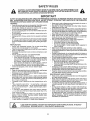
OWNER'S
MANUAL
MODEL NO,
917.255950
®
Caution: Read and
Follow All Safety
Rules And
Instructions Before
Operating This
Equipment
18.0 HP TWIN CYLmNDER
ELECTRIC START
44" MOWER
6 SPEED
GARDEN TRACTOR
. Assembly
o Operation
° Maintenance
• Service and Adjustment
, Repair Parts
3ea_s, Roebuck and Co., Chicago, IL 60684 U.S.A.
SAFETY RULES
CAUTION: ALWAYS DISCONNECT SPARK PLUG WIRE AND PLACE WIRE WHERE ITCANNOT CONTACT SPARK PLUG TO PREVENT ACCIDENTAL STARTING WHEN SETTING UP,
TRANSPORTING, ADJUSTING OR MAKING REPAIRS,
IMPORTANT
SAFETY STANDARDS
REQUIRE
OPERATOR
PRESENCE
CONTROLS
TO MINIMIZE
THE RISK OF INJURY,
YOUR
UNIT IS EQUIPPED
WITH SUCH CONTROLS.
DO NOT ATTEMPT
TO DEFEAT THE FUNCTION
OFTHE OPERATOR
PRESENCE
CONTROLS
UNDER ANY CIRCUMSTANCES,
Never mow in wet or slippery grass, when traction is unsure, or
TRAINING:
at a speed which could cause a skid.
Know the controls and how to stop quickly. Read this owner's
Stay alert for holes in the terrain and other hidden hazards.
manual end irrsttuctions furnished with attachment&
Keep away from drop--offs.
Do not allow children to operate the machine, Do not allow
Do not drive too close to creeks, ditches, and public highways.
adults to operate it without proper instruction.
Exercise special care when mowing around fixed objects in orDo not carry passenger& Do not mow when children and othdetto prevent the blades from striking them, Never deliberately
ers are around
run vehicle or mower into or' over any foreign objects.
Do not attempt to operate your vehicle or mower when not in
Never shift gears until vehicle comes to a stop.
the ddveCs seat.
Never place hands or feet under the mower, in discharge
A[ways get on or off your vehicle from tire operator's left hand
chute, or near any moving parts while vehicle or mower is FUrlside
ning. Always keep clear of discharge chute.
The vehicle and attachments should be stopped and inspected
Use care when pulling loads or using heavy equipment.
for damage after striking a foreign object, and the damage
Use only approved drawbar hitch points.
should be repaired before restarting and operating tire equipLimit loads to those you can safely control,
merit
Do not turn sharply. Use care when backing.
PREPARATION:
Use counterweight or wheel weights when suggested in
owner's manual.
Always wear substantial footwear. Do not wear loose fitting
clothing that could get caught in moving parts.
Watch out for traffic when crossing or near roadways.
Clear the work area of objects (wire, rocks, etc.) which might be
When using any attachments, never' dkect discharge of material toward bystanders nor allow anyone near the vehicle while
picked up and thrown_
in operation,
Disengage all attachment clutches before attempting to start
Except for adjustments, do not operate engthe if air cleaner or
the engine.
Handle gasoline with care - it is highly flammable.
cover directly over carburetor air intake is removed. Removal of
Use approved gasoline containers.
such part could create a fire hazard
Never remove the fuel cap of the fuel tank or add gasoline
Do not change the engine governor settings or overspeed the
to a running or hot engine or an engine that has not been
engine; severe damage or injury may resulL
allowed to cool for several minutes after running Never fill
When using the vehicle with mower, proceed as follows:
tank indoors Always clean Up spilled gasoline,
Mow only in daylight or in good artificial light.
- Open doors if the engine is run in the garage - exhaust
Shut the engine off when unclogging chute.
fumes are dangerous. Do not run the engine indoors.
Check the blade mounting bolts for proper tightness at freDo not operate the mower without the entire grass catcher, on
quent intervals.
mowers so equipped, orthe deIlector shield in place.
Disengage power to mower before backing up. Do not mow in
reverse unless absolutely necessary and then only after care*
OPERATION:
fal observation of the entire area behind the mower.
Keep your eyes and mind on your vehicle, mower, and the area
Keep the vehicle and attachments in good operating condition,
being cut Do not let other interests distract you.
and keep safety devices in place and working.
Disengage power to attachments and stop the engine before
MAINTENANCE
AND STORAGE
leaving the operator's position.
Disengage power to mower, stop th, engine, and disconnect
Keep all nuts, bolts, and screws tight to be sure the equipment
spark plug wire(s) from spark plug(s) before cleaning, making
is in safe working condiflon_
an adjustment, or repair. Be careful to avoid touching hot mufNever' store the equipment with gasoline in tire tank inside a
fler or engine components.
building where fumes may reach an open flame or spark Allow
Disengage power to attachments when transporting or not in
the engine to cool before storing in any enclosure.
use.
To reduce fire hazard, keep the engine free of grass, leaves, or
""eke all possible precautions ' hen leaving the vehicle unatexcessive grease. Do not clean product while engine is runtended. Disengage the powe, _ake-off, lower the attachments,
ning
shift ,nto neutral, set the park; nj brake, stop the engine, and reDo not operate without a muffler, or tamper with exhaust sysmove the key.
tem. Damaged mufflers or spark attesters could create a fire
hazer& Inspect periodically and replace if necessary,
Pn not stop or start suddenly when going uphill or downh!ll.
;,,ow up and down the face of slopes (not greater than 15 ),
Under normal usage the grass catcher bag material is subject
never across the face.
to deterioration and wean It should be checked frequently for
Redu,.e speed on slopes and make turns gradually to prevent
bag replacement.
Replacement bags should be checked to
tipping or loss of control Exercise extreme caution when
ensure compliance with the original manufacturer's recomchanging direction on slopes.
mendations or specifications.
While going up or down slopes, place gearshift control lever in
1st gear position to negotiate tt:e slope without stopping_
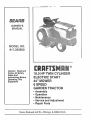
LOOK FOR THIS SYMBOL
ATTENTION!!!
BECOME
TO POINT OUT IMPORTANT
ALERT!II
YOUR
2
SAFETYIS
SAFETY
PRECAUTIONS.
INVOLVED,
IT MEANS
,,
,
I
CONGRATULATIONS
on your purchase of a Sears tractor. It
has been designed, engineered and manufactured to give you
the best possible dependablility and performance,
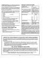
SPECIFICATIONS
HORSEPOWER:
IASOLINE CAPACITY:
Should you experience any problem you cannot easily remedy. please contact your nearest Sears Service Center/Department, They have competent, well-trained technicians and
the proper tools to repair this unit,
18.0
3,5 GALLONS
UNLEADED REGULAR
OIL (&0 PINTS w/o FILTER)
(3.5 PINTS with FILTER)
Please read and retain this manual, The instructions will enable you to assemble, operate, and maintain your unit properly, Always observe the SAFETY RULES,
MODEL
NUMBER
PRODUCT
SPARK PLUG (GAP.025 IN.):
VALVE CLEARANCE:
SAE 30 (or 10W-30)
WINTER: SAE 5W-30
CHAMPION
INTAKE ,003-.008 IN_
EXH.
917.255950
RV-15VC
GROUND SPEED:
.016-.019
iN.
(MPH):
LO
HI
SERIAL
NUMBER
1st
.8
1_8
DATE OF PURCHASE ....
2nd
1,4
&4
THE MODEL AND SERIAL NUMBERS WILL BE
FOUND ON A PLATE UNDER THE SEAT,
3rd
2_4
5.5
Rev.
.9
2.1
YOU SHOULD RECORD BOTH SERIAL NUMBER
AND DATE OF PURCHASE AND KEEP IN A SAFE
PLACE FOR FUTURE REFERENCE,
TIRE PRESSURE:
CHARGING SYSTEM:
i
MAINTENANCE
AGREEMENT
BLADE BOLT TORQUE:
A Sears Maintenance Agreement is available on this product,
Contact your nearest Sears store for detail&
CUSTOMER
15 AMPS @ 3600 RPM
3O-35 FT, LBS,
WARNING: This unit is equipped with an internal combustion
engine and should not be used on or near any unimproved forest-covered, brush-covered or grass-covered land unless
the engine's exhaust system is equipped with a spark arrester
meeting applicable local or state laws (if any). If a spark arrester is used, it should be maintained in effective working order
by the operator.
In the state of California the above is required by law (Section
4442 of the California Public Resources Code). Other states
may have similar laws. Federal laws applyon federal lands. A
spark arrester for the muffler is available through your nearest
authorized service facility (see the REPAIR PARTS section of
this manual).
RESPONSIBILITIES
• Read and observe the safety rules.
• Follow a regular schedule in maintaining, caring for and using your unJL
• Follow the instructions under "Maintenance" and "Storage"
sections of this owner's manual,
LIMITED TWO YEAR WARRANTY
FRONT: 14 PSI
REAR: 10 PSi
ON ELECTRIC
START RIDING
EQUIPMENT
For two years from date of purchase, when this riding equipment is maintained lubricated and tuned up according to the
operating and maintenance instructions in the owner's manual, Sears will repair free of charge any defect in material or
workmanship.
This Warranty does not cover:
•
•
•
Tire replacement or repair caused by punctures from outside objects (such as nails, thorns, stumps, or glass).
Expendable items which become worn during normal use, such as blades, spark plug, air cleaners and belts,
Repairs necessary because of operator abuse or negligence, including bent crankshafts and the failure to maintain
the equipment according to the instructions contained in the owner's manual
Riding equipment used for commercial or rental purposes.
FULL 90 DAY WARRANTY ON BATTERY
For 90 days from date of purchase, if any battery included with this riding equipment proves defective in material or workmanship and our testing determines the battery will not hold a charge, Sears will replace the battery at no charge,
WARRANTY SERVICE IS AVAILABLE BY CONTACTING THE NEAREST SEARS SERVICE CENTER/DEPARTMENT IN THE UNITED STATE& THIS WARRANTY APPLIES ONLY WHILE THIS PRODUCT IS IN USE IN THE
UNITED STATE&
This Warranty gives you specific legal rights, and you may also have other rights which vary from state to state.
SEARS, ROEBUCK AND CO., Di731CR-W SEARS TOWER, CHICAGO, IL 60684
3
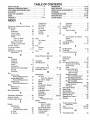
TABLE OF CONTENTS
SAFETY RULES .............
PRODUCT SPECIFICATIONS
.,.
CUSTOMER RESPONSIBILITIES .
WARRANTY ................
TABLE OF CONTENTS ........
INDEX .....................
ASSEMBLY .................
OPERATION
.............
MAINTENANCE
............
SERVICE AND ADJUSTMENTS
STORAGE ................
TROUBLESHOOTING
.......
REPAIR PARTS ............
SLOPE SHEET .............
,,l°,,i,,,°t,2
o,,,°,°,_,,,°3
omu==°°,_,=,,5
=,at=lOm_,_°_4
..........
7-10
.............
...........
...........
.............
...........
...........
.............
11-14
15-18
19-25
26
27-28
30-53
55
INDEX
A
Adjustment, Attachment Lift Spdng. 23
Adjustments:
Brake ...................
21
Carburetor ..............
25
Clutch Pulley ..............
21
Gauge Wheels ..........
13
Mower:
Front-To-Back
.......
20
Side-To-Side
.........
19
Mower Drive Belt ...........
20
Throttle Control Cable .......
25
Air Filter, Engine ..........
18
Air Screen, Engine ...........
18
Assembly
.................
7--10
Attachment Lift Spring:
Adjustment ..............
23
B
Replacement ..............
Sharpening ...............
Brake Adjustment ..............
16
16
21
C
Carburetor, Adjustment ..........
Controls, Tractor ...............
Cutting Height, Mower ..........
25
11
12
E
.
25
25
18
18
18
17
13,17
17
13
14
26
Filter:
Air Cleaner ................
Fuel ..................
Oil ......................
Fuel:
Storage .................
Type .....................
Fuse ........................
18
18
18
13
23
24
L
Leveling Mower Deck ........
Lubrication, Chart .............
19--20
15
M
Maintenance
...............
15--18
Air Filter .................
v, 18
Foam Pre-Cleaner ......
18
Air Screen, Engine .........
18
Battery ..................
17
Blade ...............
'
16
Cooling Fins, Engine .........
18
Engine Oil ................
17
Fuel Filter .................
18
Lubrication Chart ..........
15
Schedule ..................
15
Spark Plugs ...............
18
Tire Care ..............
8,15,22
Tractor:
Transaxle Oil Level .......
16
Mower:
Adjustment:
Front-To-Back
..........
20
Side-To-Side
...........
19
Blade Replacement
.........
16
Blade Sharpening ..........
16
Cutting Height .............
12
Installation ................
9
4
13
19
14
18
3, 35
O
Oil:
Cold Weather Conditions . 13,17
Engine .................. 17
Transaxle ................. 16
Operating Mower ...............
13
Operation .................
11--14
Parking Brake ...............
11,12
Parts Bag ......................
6
Product Specifications ........... 3
S
.....
H
Headlights ....................
Hood Removal ...............
Operation ................
Removal .................
Mowing Tips ..................
Muffler ......................
Spark Arrester ..........
P
26
14
23
G
Gauge Wheels, Adjustment
Battery:
Charging ................
8
Cleaning .................
17
Installation ...............
8
Levels .................
8,17
Preparation ...............
8
Starting with Weak Battery . . 23
Storage ..................
25
Terminals ...............
17
Belt:
Motion Drive:
Removal/Replacement
....
22
Mower Blade Drive:
Removal/Replacement
[...
21
Mower Drive:
Removal/Replacement
....
20
Blade:
Engine:
Adjustments:
Carburetor
............
Throttle Control Cable
Air Filter'. .................
Air Screen ...............
Cooling Fins ...............
Oil Change ................
Oil Level ...............
Oil Type ..................
Preparation
..............
Starting ...................
Storage ..................
Safety Rules ....................
2
Schematic ....................
29
Seat .......................
8
Service and Adjustments .....
19--25
Attachment Lift Spring ......
23
Clutch Pulley ..............
21
Fuse ..............
i : .....
23
Mower Adjustment
Front-To-Back
.........
20
Side-To-Side
.........
19
Motion Drive Belt:
Removal/Replacement
.... 22
Mower Blade Ddve Belt:
Removal/Replacement.
.... 21
Mower Drive Belt:
Removal/Replacement
.... 20
Mower Removal ............
19
Tire Care .............
6"16"22
Slope Guide Sheet ..............
55
Spark Plugs ................... 18
Specifications ..................
3
Starting the Engine ..............
14
Steering Wheel ...............
7,22
Stopping the Tractor .............
12
Storage .......................
26
T
Throttle Control Cable:
Adjustment ................
Tires .....................
Troubleshooting ............
25
8,16,22
27--28
W
Wiring Schematic
.............
29
--
ii
i,
ACCESSO
J.
,it
,,,,
ES AND ATTACHMENTS
nl
These accessor es and attachments were available when the unit was purchased, They are also available at most Sears retail
outlets, catalog and service centers. MOSLSears stores can order these items for you when you provide the mode[ number of
your tractor,
ENGINE
SPARK PLUG
MAINTENANCE
MUFFLER
AIR FILTER
GAS CAN
ENGINE OIL
STABILIZER
BLADES
BELTS
PERFORMANCE
Sears offers a wide variety of attachments that fit your vehicle, Many of these are listed below with brief explanations of how
they can helpyou, This list was current at the time of publication; however it may change in future years- more attachments
may be added, changes may be made in these attachments, or some may no longer be available or fit your model, Contact
your nearest Sears store for the accessories and attachments that are available for your unit,
Most of these attachments do not require additional hitches or conversion kits (those that do are indicated) and are designed for
easy attaching and detaching
TRACTOR CAB has heaw duty vinyl fabric over tubular steel
frame, ABS plastic top; clear plastic windshield offers 360 degree
visibility_ Hinged metal doors with catch_ Keeps operator warm
and dry. Remove vinyl and windshields for use as sun protector in
summer.
LAWN SWEEPERS let you collectgrass clippings and leaves.
LAWN VACS for powerfial collection of heavy grass clippings and
leaves, Wand attachment to pick up debds in hard-to-reach
places,
CARTS make hauling easy_ Variety of sizes available.
ROLLER for smoother lawn surface. 36-inch wide, 18 inch diameter water-tight drum holds up to 390 Ibs, of weighL Rounded
edges prevent harm to tUrfr Adjustab{e scraper automatically
cleans drum,
Optional accessories for tractor cab: tinted/tempered solid
safety glass windshield with hand operated wiper; 12-volt amber
caution light for mounting on cab top
TRACTOR COVER protects tractor from weather, Made of Evolution 3 fabric (water-repellent, extremely breathable, light weight,
soft, non-abrasive, pliable in all temperatures, durable, stain/tear/
puncture resistant, will not shrink or stretch)
SPREADER/SEEDERS make seeding, fertilizing, and weed killing
easy, Broadcast spreaders are also useful for granular de-icers
and san&
TILLER has 8hp engine to prepare seed beds, cultivate and compost garden residue. Chain--drive transmission. Six 11-inch diameter one piece heat-treated steeltines. Tills 30-inch path (Requires sleeve hitch.)
CORING AERATOR takes small plugs out of soil to allow moisture
and nutrients to reach grass roots 36-inch swath. 24 hardened
steel coring tips, 150 Ib, capacity weight tray.
AERATOR promotes deep root growth for a healthy lawn. Tapered 2.5" steel spikes mounted on 10-in. diameter discs puncture
holes in soilat close intervalsto let moisture soak in. Steel weight
tray for Increased penetration.
DOZER BLADE removes snow; grades dirt, sand and gravel. 48
inches wide, 17 inches high, clears 44.-inch path when angled
Master lift control lever for operator ease. Spring trip for snow removal on uneven pavement; built-in float for blade to fallow
ground contour. Reversible, replaceable scraper bar. (Use with tire
chains, wheel weights or rear drawbar weight.)
DETHATCHER loosens soil and flips thatch and matted leaves to
lawn surface for easy pickup, Twenty spring line teeth. Useful to
preparebare areas for seeding. Available for front or rear mounting,
SPRAYERS use 12-volt DC electric motor that connects to the
tractor battery or other 12-volt source. Includes booms for automatic spraying when pulling, and hand held wand for spot sprayIng. Wand has ad ustable spray pattern. For applying herbicides,
insecticides, f_ng'c_des,and liqu'd fert'lizers..
REAR BLADE is 42-inches wide and operated from driver's seal
Reversible steel blade can be angled at 30 degrees for grading
Reverses for snow plowing. (Requires sleeve hitch.)
SLEEVE
seeding,
sweeps_
Optional
openings
SNOWTHROWER has 40-inch swath, Drum-type auger handles
powdery and wet/heavy snow. Mounts easily with simple pin arrangementr Discharge chute adjusts from tractor seat. 6-inch diameter spout discharges snow 10 to 50 feet, Uft controlled at tractor seat. (Use with chains, wheel weights, or rear drawbar weighL)
CULTIVATOR is 43-inches wide_ Prepares ground for
helps weed controlr Steel frame holds 5 adustable
Adjusts vertically, horizontally.
(Requires sleeve hitch.)
accessory for cultivator: steel furrow opener for wider
for potatoes, corn, and other deep-seeded crops
PLOW turns s0il 6 inches deep, cuts 10-inch furrow Crank adjustment controls depth, 3-position yoke sets width. Heavy steel landslide for straight furrowing. (Requires sleeve hitch.)
DISC HARROW has 2 gangs Of4 steel blades that angle from 10 to
20 degrees, 40-inches wide. Can hook 2 units in tandem
(Requires sleeve hitch.)
TIRE CHAINS are heavy duty; closely spaced extra-large cross
links give smooth ride, outstanding traction.
WHEEL WEIGHTS for rear wheels provide needed traction for
snow removal or dozing heaw materials. (55 Ibs each.)
WEIGHT BRACKET for drawbar for snow removal applications
Can be mounted on front of tractor for plowing applications. Uses
(1) 55 lb. weight.
SLEEVE HITCH for use with master lift system
ples/i,ncouples.
5
Single pin cou-
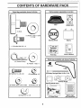
CONTENTS
OF HARDWARE
PACK
illl
i
Parts Bag contents shown full size
Parts, packed separately
Seat
in carton
Battery acid
(1) Knob
E
(1) Washer 17/32 x 1 3/16
x 12 Ga.
Steering Wheel
(1) Shoulder Bolt 5/16 - 16
Battery
i
I
i
I
I', _---"
"_ L
Owner's Manual
Parts Bag
....
i
i¸
.
Parts bag contents
i
ill¸
ill
not shown full size
(4) Retainer Spring
(4) Washer 11/32 x 1
(2) Keys
illlll
(2) Hex Bolt, 1/4,20
illlll I
x 3/4
ii
(2) Battery Carriage Bolts 1/4-20 x 7-1/2
(2) Lockwasher, 1/4
@
(2) Washer, 9/32 x 5/8 x 16 Ga.
V-Br
@
Terminal Guard
Steering Wheel Insert
(2) Hex Nut, 1/4 - 20
m
.........
I,
t
(2) Wing Nut, 1/4 - 20
15 ° Slope Sheet
6
Battery Caps
and Instructions
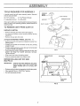
ASSEB BLY
TOOLS
REQUIRED
FOR ASSE!_BLY
(2) 7/16" wrenches
(I) Tire Pressure Gauge
(1) Adjustable Wrench
(1) Utility Knife
_:)
STEERING
WHEEL_z;
INSERT
A socket wrench set will make assembly easier. Standard
wrench sizes are listed.
HEXBOLT
When right or left hand is mentioned in this manual, it means
when you are in the operating position (seated behind the
steering wheel).
_._
_
. LOCKWASHER
STEER'NGWHEEL
//
FLAT W;-',SitER
/
TO REMOVE UNIT FROM CARTON
UNPACK
£TEE
',
_VI-IE'EL
ADAPTEF
CARTON
° Remove all loose parts from carton (See page 6)
• Cut, from top to bottom, a!l four corners of carton and lay
panels flat
• Remove mower deck from skid.
ATTACH
STEERING
WHEEL
(See FiG, 1)
o Remove hex bolt. lock washer and large flat washer from
steering shaft
• Position front wheels of the tractor so they are pointing
straight forward
• Position steering wheel so cross bars are horizontal (left
to right) and slide onto adapter_
o Secure steering wheel to steering shaft with hex bolt, lock
washer and large flat washer previously removed.
Tighten securely
• Snap insert into center of steering wheel.
• Remove protective plastic from tractor hood
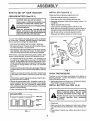
BEFORE ROLIJNG
(See FIG, 2)
IMPORTANT"
FIG. 1
CLUTCH/BRAKE
PEDAL
LIFT LEVER
UNIT OFF SKID
[
CHECK FOR AND REMOVE ANY STAPLES IN SKID THAT MAY PUNCTURE
TIRES WHERE UNIT IS TO ROLL OFF
SKID.
P
• Release parking brake by depressing clutch/brake pedal
• Place gearshift lever in "NEUTRAL" position.
• Roll unit backwards off skid,
__J
2
\
GEARSHIFT
LEVER
FIG, 2
7
\
,i
ASSEMBLY
HOW TO SET UP YOUR TRACTOR
INSTALL
SEAT
(See
FIG. 4)
Adjust seat before tightening adjustment knob.
PREPARE
BATTERY
CAUTION:
(See
FIG. 3)
• Remove cardboard packing on seat pan.
• Place seat on pan and assemble shoulder bolt,
• Assemble adjustment knob and flat washer loosely. Do
not tighten.
• Tighten shoulder bolt securely.
• Lower seat into operating position and sit on seal
• Slide seat until a comfortable position is reached which allows you to press clutch/brake pedal all the way down,
• Get off seat without moving its adjusted position,
Wear eye and face shield.
Wash hands or clothing immediately If accidentally in contact with battery acid.
acid
aresmoke.
explosive.
Do not
Fumes from charged battery
Read the instructions
included with the
battery vent caps in the bag of parts. Always wear gloves, clothing and goggles to
protect your hands, skin and eyes,
• Raise seat and tighten adjustment knob securely.
Your unit has a battery charging system which is sufficient
for normal use_ However, periodic charging of the battery
with an automotive charger will extend its life_
SEAT
SHOULDER
_OLT
° See instructions packed with vent caps in parts bag,
° Fill battery with acid. Fill each cell until it reaches the bottom of the vent wells_ Do not over fill.
FLAT
WASHER
• Allow battery to stand and settle for at least thirty minutes.
After standing, check the level of acid. if below the vent
wells, add more acid until the correct level is reached.
While battery is standing (after adding acid) and later, while
battery is being charged, continue with assembly of unit.
• To maximize the life of your battery, it is necessary that
the battery be charged before use. Use a 12 volt battery
charger. Charge battery at a rate of 6 amperes for 1 hour.
Observe all safety precautions required for battery charging. Failure to charge battery can result in a shortened
battery life
I
PAN
SEAT
ADJUSTMENT
KNOB
. Check the acid level after the battery is charged_ If the acid
has fallen below the correct level, add distilled or iron free
water,
FIG. 4
• Install the vent caps to coyerthe vent wells. Wash the top
of the battery with water to remove any acid, then wipe
dry,
• Check battery case for leakage to make sure that no damage has occurred in handling.
• Dispose of excess battery acid, Neutralize acid for disposal by adding it to four inches of water in a five gallon
plastic container. Stir with a wooden or plastic paddle
while adding baking soda until the addition of more soda
causes no more foaming,
• Follow instructions orr how to install battery,
CUT AWAY
"_""'-
PRESSURE
• ReducetirepressuretoPSIshownin"PRODUCTSPECIFICATIONS on page 3 of this manual.
INSTALL
BATTERY
(See
FIGS.
5 & 6)
CAUTION: Do not short battery terminals.
Before installing battery, remove metal
bracelets, wristwatch bands, rings, etc.
Positive terminal must be connected first
to prevent
sparking
from
accidental
grounding.
VENT CAP
_
_
TIRE
The tires on your unit were overinflated at the factory for
shipping purposes_ Correct tire pressure is important for
best cutting performance,
VIEW
I
L.,,.-..J
CHECK
ATTERY
TUBE
• Raise hood.
BATTERY
CELL
• Make sure drain tube is fastened to drain hole in battery
tray and battery tray is positioned in hole of battery support.
• Place battery in plastic tray, battery terminals to front of
tractor°
FIG. 3
8
ASSEMBLY
INSTALL
• First connect RED battery cable to positive (+) battery terminal with hex bolt, flat washer, Iockwasher and hex nut
as shown. Tighten securely.
• Connect BLACK grounding cable to negative (-) battery
terminal with remaining hex bolt, fiat washer, Iockwasher
and hex nut. Tighten securely,
. Slide the two battery bolts through terminal guard and
start wing nuts onto threads.
, Position terminal guard over battery as shown, lower botts
into key holes and slide square shafts of bolts into slots of
key holes.
• Tighten wing nuts by hand making sure battery botts remain in slots of key holes in battery support.
• Be sure terminal access doors are closed,
Use terminal access doors for:
•
•
,
•
MOWER
AND DRIVE
BELT
Your unit has been shipped with the front mower suspension
bracket banded to the frame. Remove bands and pivot
bracket downward.
MOWER INSTALLATION
(See FIGS. 7, 8, 9 and 10)
• Remove banding from suspension arms and gauge
wheels. Set gauge wheels aside for later assembly.
• Slide mower under tractor with discharge guard to right
side of tractor,
• Slide front suspension brackets into mower brackets, Retain with release pins (FIG. 7), Turn depth adjustment
knob counterclockwise until it stops. Lower mower linkage with attachment lift lever (See FIG. 12)_
• Slide studs through lift links on both sides eftractor, Retain with washers and retainer springs.
• Place the suspension arms on brackets on both sides of
frame (See FIG 8). Retain with washers and retainer
springs.
• Place suspension arms in rear suspension brackets, Retain with release pins.
• Turn depth adjustment knob clockwise to remove slack
from mower suspension.
• Insert gauge wheel bar into bracket (See FiG, 7)_ Retain
with clevis pins and retainer springs.
Inspection for secure connections (to tighten hardware)
inspection for corrosion
Testing battery
Jumping (if required)
Periodic charging
POSITIVE
(RED)
CABLE
DEPTH ADJUSTMENT
{
KNOB
SUSPEN- _
S,ON
.. ".
FLAT
WASHER
NEGATIVE
BELT
I
.
I
HEX
BOLT
_BLACK]
ABLE
FIG. 5
VENT
CAP
.... \\
WING
PRONT
I
/
suePEN.
I
TERMINAL
GUARD
ACCESS
DOORS
/_
/
-
_ RELEASEI
[V
PIN
FIG. 7
RETAINER
BATTERY
BOLT
KEY
HOLE
BATTERY
TRAY
BATrERY
SUSPENSION
DRAIN
TUBE
"__1_
ARM "_
WASHER_----_--_',=_
RETAINER _"_'__
FIG. 6
SPRINGF
/ b_
t_.-I /._....
_ _"t._",,..,,.,._
''-'_,-j
_
,_"'_,
-_',,_Q
FIG. 8
9
_
WASHER
LIFTLINK
_ STUD
I
ASSEMBLY
CHECK
GAUGE
WHEEL
r_ -...-----'
RETAINER
DECK
LEVELNESS
For best cutting results, mower housing should be properly
leveled. See "TO LEVEL MOWER HOUSING" in the Service and Adjustments section of this rnanual
BAR_
GAUGE
CHECK
BELTS
BRACKET
_
WHEEL,/
POSITION
OF ALL
See the figures that are shown for replacing motion, mower
drive, and mower blade drive belts in the Service and Adjustrnents section of this manual Verify that the belts are routed
correctly.
CLEVIS
PIN
FIG. 9
DRIVE BELT INSTALLATION
FOR PROPER
CHECK
BRAKE
SYSTEM
(See FIGS. 10 and 11)
After you learn how to operate your !ractor, check to see t!_at
the brake is properly adjusted, See 'TO ADJUST BRAKE in
the Service and Adjustments section of this manual
• Remove hood and grill (See "TO REMOVE HOOD AND
GRILL ASSEMBLY" in the Service and Adjustments section of this manual,
,/'CHECKLIST
• Roll mower drive belt over primary mandrel.
• Roll mower drive belt forward over front mower suspension bracket.
BEFORE YOU OPERATE AND ENJOY YOUR NEW
TRACTOR, WE WISH TO ASSURE THAT YOU RECEIVE
THEBESTPERFORMANCEAND
SATISFACTIONFROM
THIS QUALITY PRODUCT.
PLEASE REVIEW THE FOLLOWING CHECKLIST:
• Place mower drive belt over clutch pulley on engine and
under idler pulley and tension pulley.
• Replace hood and grill assembly.
NOTE: Pull tension pulley lever forward for belt clearance
Make sure narrow "V side of belt is engaged with each pulley, and push tension pulley lever back to operating position.
PRIMARY
MANDREL
,/All assembly instructions have been completed_
,/No
,/" All tires are properly inflated. (For shipping purposes, the
tires were overinflated at the factory.)
¢" Be sure mower deck is properly leveled side-to-side/
front-to-rear for best cutting results. (Tires must be properly inflated for leveling.)
,/Check mower and drive belts. Be sure they are routed
properly around pulleys and inside all belt keepers_
,/Check wiring. See that ali connections are still secure and
wires are properly clamped.
WHILE LEARNING HOW TO USE YOUR TRACTOR, PAY
EXTRA ATTENTION TO THE FOLLOWING IMPORTANT
ITEMS:
FIG, 10
PULLEY'-'------.----..-_lp
MORON
RIVE
,/Engine
CLUTCH
LEVER_
oil is at proper level
,/Fuel tank is filled with fresh, clean, regular unleaded gasoline.
,/Become familiar
withallcontrols-their
location
and function.Operate them beforeyou start
theengine.
,/Be sure brake system isinsafeoperatingcondition.
BELT
DLER
ULLEY
TENS,ON
remaining loose parts in carton.
,/Battery is properly prepared and charged.
(Minimum 1
hour at 6 arnps).
,/Seat is adjusted comfortably and tigt_tened securely_
MOWER
DRIVE
L...
FIG. 11
10
ii
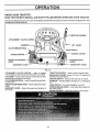
OPERATION
KNOW YOUR TRACTOR
READ THIS OWNER'S MANUAL AND SAFETY RULES BEFORE OPERATING YOUR TRACTOR.
C0rnpare the illustrations with your Tractor to familiarize yourself with the locations of various controls and adjustments
this manual for future reference.
RW
I
THROTTLE
ATTACHMENT
CLUTCH
CONTROL
SWITCH
AMMETER
CLUTCH/BRAKE
Save
LIFT LEVER
PEDAL
LIGHT SWITCH
IGNITION
HEIGHT ADJUSTMEN3"
KNOB
GEARSHIFT
SWITCH
PARKING
BRAKE
LEVER
RANGE SHIFT LEVER
LEVER
FIG. 12
ATTACHMENT
CLUTCH SWITCH - Used to engage
mower blades or ether attachments mounted to your tractor,
LIFT LEVER - Used to raise and lower mower deck or other
attachments mounted to your tractor,
CLUTCH/BRAKE PEDAL- Used for declutching and braking the tractor_
HEIGHT ADJUSTMENT KNOB- Used to adjust the mower
height,
GEARSHIFT LEVER - Selects the speed and direction of
the tractor
THROTTLE CONTROL - Used to control engine speed.
RANGE SHIFT LEVER -Allows "HI" and "LO" speed for all
forward and reverse gears.
IGNITION SWITCH - Used to start and stop the engine,
AMMETER - Indicates battery charging (+) or discharging
LIGHT SWITCH -Turns the headlights on and off,
PARKING BRAKE LEVER - Locks clutch/brake pedal into
the brake position,
CHOKE CONTROL - Used when starting a cold engine,
11
m
OPERATION
The operation of arty tractor can result In foreign objects thrown Into the eyes, which can result
in severe eye damage. Always wear safety glasses or eye shields while operating your tractor or
before performing any adjustments or repairs. We recommend wide vision safety mask for over
the spectacles or standard safety glasses, available at Sears Retail or Catalog Stores.
HOW TO USE YOUR TRACTOR
TO SET PARKING
BRAKE
CLUTCH/BRAKE
PEDAL "BRAKE"
POSITION
(See FIG. 13)
"DRIVE"
POSITION
= Depressclutch/brakepedalintofull"BRAKE"positionand
hold,
ATTACHMENT
CLUTCH SWITCH
• Place parking brake lever in "ENGAGED" position and release pressure from clutch/brake pedal Pedal should remain in "BRAKE" position, Make sure parking brake will
hold vehicle secure,
STOPPING
(See FIG. 13)
MOWER BLADES • Move attachment
tion,
CHOKE
clutch lever to "DISENGAGED"
posi-
GROUND DRIVE° Depress clutch/brake
pedal into full "BRAKE" position.
IGNITION
KEY
° Movegearshiftleverto"NEUTRAL"position_
ENGINE o Move throttle control to "SLOW" position_
• Turn ignition key to "OFF" position and remove key. Always remove key when leaving vehicle to prevent unauthorized use,
THROTTLE
CONTROL
LEVER
HEIGHT
ADJUSTMENT
KNOB
PARKING BRAKE
"DISENGAGED"
POSITION
• Never use choke to stop engine.
TO USE CHOKE
CONTROL
(See FIG. 13)
Use choke control whenever you are starting a cold engine.
Do not use to start a warm engine.
GEAR
SHIFT
LEVER
° To engage choke control, pull knob out, Slowly push knob
in to disengage,
TO USE THROTTLE
CONTROL
FIG. 13
(See FIG. 13)
Always operate engine at full throttle,
TO ADJUST
FIG. 13)
• Operating engine at less than full throttle reduces the battery charging rate and the engine cooling air flow,
• Full throttle offers the best mower performance,
TO MOVE FORWARD
FIG. 13)
AND BACKWARD
MOWER
CUTTING
HEIGHT
(See
The cutting height is controlled by turning the height adjustment knob in desired direction.
(See
• Turn knob clockwise to raise cutting height.
° Turn knob counterclockwise to lower cutting height.
The direction and speed of movement is controlled by the
gear shift lever
The cutting height range is approximately (1-1/4"to 3-3/4")_
The heights are measured from the ground to the blade tip
with the engine not running, These heights are approximate
and may vary depending upon soil conditions, height of
grass and types of grass being mowed
° Start unit with clutch/brake pedal depressed and the
gearshift lever in "NEUTRAL" position.
• Move gearshift and range shift levers to desired position,
• Slowly release clutch/brake pedal to start movement.
IMPORTANT:
RANGE
SHIFT
LEVER
• The average lawn should be cut approximately 2-1/2
inches during the cool season and over 3 inches during
hot months. For healthier and better looking lawns, mow
often and after moderate growth.
, For best cutting performance, grass over 6 inches in
height should be mowed twice. Make the first cut relatively
high; the second to desired height.
BRING TRACTOR TO A COMPLETE
STOP BEFORE SHIFTING OR CHANGING GEARS
12
OPERATION
irr
TO ADJUST
GAUGE
WHEELS
(See FIG.
TO OPERATE
14)
• Adjust mower to desired cutting hetghtr
• Lower mower with lift contrOlr Remove rear retainer spring
and clevis pin which secure each gauge wheel,
, Lower gauge wheels to ground. Raise gauge wheels
slightly to align holes in bracket and gauge wheel bar and
insert clevis pins. Gauge wheels shouldbe slightly off the
ground
• Replace retainer springs into clevis pins,
,_
/
ON HILLS
CAUTION: DO not drive up or down hillsi-"
with slopes greater than 15 and do not R
drive across any slope.
• Choose the slowest speed before starting up or down
hills.
• Avoid stopping or changing speeds on hills
• If slowing is necessary, move throttle control lever to
slower position.
• If stopping is absolutely necessary, push clutch/brake
pedal quickly to brake position and engage parking brake
• Move gearshift lever to "NEUTRAL" position,
• To restart movement, move gearshift lever to 1st gear and
range shift lever to "LO" position, Be sure you have allowed room for unit to roll slightly as you restart movement,
RETAINER
.
-,,,i
SPRING
GAUGE
WHEEL
BAR_
BRACKET
• Slowly release parking brake and clutch/brake pedal.
• Make all turns slowly.
f
TO TRANSPORT
CLEVIS
PINS
• Raise attachment to highest position with lift control.
• When pushing or towing your unit. be sure gearshift lever
is in "NEUTRAL" position.
• Do not push ortow unit at more than five (5) MPH,
FIG.14
TO OPERATE
MOWER
(See
FIGS.
12 and 13 )
BEFORE
Your unit is equipped with an operator presence sensing
switch. Any attempt by the operator to leave the seat with
the engine running and the attachment clutch engaged will
shut off the engine.
STARTING
THE ENGINE
CHECK
ENGINE
OIL LEVEL (See FIG. 16)
• The engine in your unit has been shipped, from the factory, already filled with summer weight oil,
• Check engine oil with unit on level ground.
• Remove dipstick and wipe clean, replace, wait for a few
seconds, remove and read oil level. If necessary, add oil
until "FULL" mark on dipstick is reached, Do not overfill
• For cold weather operatlonyou should change oil for easier starting (see "OIL VISCOSITY CHART" in the Maintenance section of this manual),
. Select desired height of cut, using height adjustment
knob,
• Lower mower with lift lever.
• Engage mower by pulling attachment clutch switch up
and out to "ENGAGED" position.
• TO STOP MOWER - Move attachment clutch switch to
"DISENGAGED" position,
• Raise mower with lift lever,
• To change engine oil, see the Maintenance section in this
manual.
out either the entire grass catcher (on
mowers so equipped) or the discharge
CAUTION: Do notoperatethe
mower withguard In place.
}_
ENGINE OIL
FILLER CAP
J
DIPSTICK
GUARD
FIG. 15
FIG. 16
13
OPERAT[O
MOWING
TIPS
• Tire chains cannot be used when the mower housing isattached to unit.
ADD GASOLINE
• Fill fuel tank. Use fresh, clean, regular unleaded gasoline.
(Use of leaded gasoline will increase carbon and lead oxide deposits and reduce valve life)
IMPORTANT:
• Mower should be properly leveled for best mowing performance. See TO LEVEL MOWER HOUSING"in the
Service and Adjustments section of this manual
° Use the runner on the right hand side of mower as a guide.
The blade cuts approximately an inch outside the runner
(See FIG. 15).
° The left hand side of mower should be used for trimming.
• Drive so that clippings ere discharged onto the area that
has been cut. Have the cut area to the right of the machine. This will result in a more even distribution of clippings and more uniform cutting
° When mowing large areas, start by turning to the right so
that clippings will discharge away from shrubs,, fences.
driveways, etc. After one or two rounds, mow in the opposite direction making left hand turns until finished (See
FIG, 17).
WHEN OPERATING IN TEMPERATURES
BELOW 32°F (0°C). USE FRESH CLEAN
WINTER GRADE GASOLINE TO HELP
INSURE
GOOD
COLD
WEATHER
STARTING,
WARNING: Experience indicates that alcohol blended fuels
(called gasohol or using ethanol or methanol) can attract
moisture which leads to separation and formation of acids
during storage, Acidic gas can damage the fuel system of an
engine while in storage, To avoid engine problems, the fuel
system should be emptied before storage of 30 days or
longer_ Drain the gas tank, start the engine and let it run until
the fuel lines and carburetor are empty. Use fresh fuel next
season. See Storage sections of this manual for additional
information. Never use engine or carburetor cleaner prOducts in the fuel tank or' permanent damage may occur.
CAUTION=
Fill to bottom
of gas tank flllerJ
neck.
Do not
oil
or fuel.
Do overfill.
not store,Wipe
spillofforany
usespllledl
gaso-|
line near an open flame.
TO START
(See FIG. 13)
ENGINE
When starting engine for the first time or if engine has run out
of fuel, it will take extra cranking time to move fuel from the
tank to the engine_
•
•
o
•
Depress the clutch/brake pedal and set the parking brake
Place gearshift lever in "NEUTRAL" position.
Move attachment clutch to "DISENGAGED" position,
Pull choke control out to "CHOKE" pesition for cold engine start. For warm engine start do not use choke control
FIG. 17
• Move throttle control to midway between "FAST" and
"SLOW" positions,
° Turn ignition key clockwise to "START" position and release key as soon as engine starts, Do not run starter
continuously for more than fifteen seconds per minute, If
engine does not sta.rt after several attempts, move throttle control tO 'FAST' position, wait a few minutes and try
again
• When engine starts, slowly push choke control in.
• Move throttle corrtrol to "FAST" position.
• Allow engine to warm up for a few minutes before engaging clutch/brake pedal or attachment clutch switch,
• If grass is extremely tall, it should be mowed twice to reduce load and possible fire hazard from dried clippings.
Make first cut relatively high, the second to the desired
height.
° Do not mow grass when it iswet, Wet grass will plug mower and leave undesirable clumps. Allow grass to dry before mowing.
° Always operate engine at full throttle when mowing to assure better mowing performance and proper discharge of
material.
Regulate ground speed by selecting a low
enough gear to give the mower cutting performance as
well as the quality of cut desired
• When operating attachments, select a ground speed that
will suit the terrain and give best performance of the attachrnent being used.
NOTE: If at a high al_tude (above 3000 feet) or in cold temperatures (below 32 F). the carburetor fuel mixture may
need to be adjusted for best engine performance. See "TO
ADJUST CARBURETOR" in the Service and Adjustments
section of this manual,
ii
i
HI
.
i
ii
CAUTION= Before driving the tractor, In_
stall mower or remove front mower sus |
penslon bracket and suspension arms.
J
!
14
FILLIN DATES
,__'_._
_A£,_
_
A,,,__,
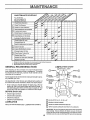
REGULAR SERVICE
Ull
_f_FSERVICE
lU,,
DATES
Check Brake Operation
i
aT CheckTire
Pressure
Check for Loose
Fasteners
A
Sharpen/Replace Mower Blades
T
Lubricate
PivotLevel/Recharge
Points
Check
Battery
a
Clean Battery and Termlnals
Lubricate Tie Rod Ball Joints
Check Engine Oil Level
v'
Change Engine Oil
Clean Air Filter/Foam Pre-cleaner
Clean Air Screen
G
I
N
J_
Inspect Muffler/Spark Arrester
Change Engine Oil Filter
_,2
i __
Clean Engine Cooling Fins
Replace Spark Plug
Replace Alr Filter Paper Cartridge
Rep,!ace Fuel Filter
1 - Change more often when operating under a heavy load or In high ambient temperatures
2 - Service more often when operating In dirly or dusty conditions
3 * Replace blades more often when mowing in sandy soil
GENERAL
RECOMMENDATIONS
LUBRICATION
CHART
TIERODBALLJOINTS
The warranty on this unit does not cover items that have
been sub ected to operator abuse or negligence, To receive
fu va ue from the warranty, operator must maintain unit as
instructed in this manual.
@SP,NOLE.
_SP,,O,.E®
Some adjustments will need to be made periodically to properly maintain your unit,
STEERING
SECTOR,-""""_"
GEAR
All adjustments in the Service and Adjustments section of
this manual should be checked at least once each season.
ENGINE @
• Once a year you should replace the spark plug, clean or
replace air filter, and check blades and belts for wear. A
new spark plug and clean air filter assure proper air-fuel
mixture
and help your engine
BEFORE
•
•
•
•
Check
Check
Check
Check
run better
and last longer.
EACH USE
PLAT_
engine oil level.
brake operation,
tire pressure.
for loose fasteners,
•
I \C,UTC.
PIVOT
LUBRICATION
Keep unit well lubricated (See "LUBRICATION
L
GENERAL
CHART")
PURPOSE
®
GREASE
REFER TO ENGINE MAINTENANCE
SECTION
SAE 30 MOTOR OIL API - se, SE, or SF
SPRAY SILICONE LUBRICANT
(MOVE BOOTS TO LUBRICATE)
IMPORTANT: Do net or!or grease the pivot points whichhavespecial
nylon bearings,Viscous lubricants will attract dust and dirt thet will
shorten the life of the self-lubricating bearings. If youfeel they must be
lubricated, use only a dry, powdered graphitetype lubricant sparingly.
15
MAINTENANCE
TRACTOR
TO SHARPEN
Always observe safety rules when performing any mainte*
nance
Care should be taken to keep the blade balanced. An unbalanced blade will cause excessive vibration and eventual
damage to mower and engine,
TIRES
BLADE
(See FIG. 19)
° The blade can be sharpened with a file or on a grinding
wheel. Do not attempt to sharpen while on t!le mower.
• To check blade balance, drive a nail into a beam or wall.
Leave about one inch ofthe straight nail exposed. Place
center hole of blade over the head of the nail If blade is
balanced, it should remain in a horizontal position. If
either end of the blade moves downward, sharpen the
heavy end until the blade is balanced.
• Maintain proper air pressure in all tires (See "PRODUCT
SPECIFICATIONS" on page 3 of this manual).
• Keep tires free of gasoline, oil, or insect control chemicals
which can harm rubber.
• Avoid stumps, stones, deep ruts, sharp objects and other
hazards that may cause tire damage
BLADE CARE
For best results mower blades must be kept sharp. The
blades can be sharpened yvith a file or on a grinding wheel.
We suggest they be sharp.ened or replaced after every 25
hours of mowing, Check blades more often if mowing in
sandy conditions.
• Do not attempt to sharpen blades while they are on the
mower,
• Replace bent or damaged blades.
BLADE
REMOVAL
BLAD
(See FIG, 18)
• Raise mower' to highest position to allow access to
blades
• Remove hex bolt, Iockwasher and flat washer secudng
blade
FIG. 19
° Install new or resharpened blade with trailing edge up towards deck as shown.
CHECK
TRANSAXLE
FIG. 20)
o Reassemble hex bolt, tockwasher and fiat washer in exact
order as shown.
• Tighten bolt securely (30-35 Ft Lbs. torque)
IMPORTANT:
BLADE BOLT IS GRADE
TREATED_
5
OIL LEVEL
(See
. Block up rear axle securely or use a tractor'jack,
• Remove left rear wheel by removing hub bolts,
° Remove filler plug from transaxle. Oil level must be even
with plug threads. If nec'essary, fill with SAE 30 oil APISD. SE. or SF, Replace filler' plug,
• Reassemble wheel to hub.
HEAT
BLADE
TRANSAXLE
FILLER
PLUG
O
MANDREL
ASSEMBLY
WASHER ......
LOCKWASHE
HEX
BOLT
GR. 5
FIG. 20
A GRADE 5 HEAT TREATED BOLT
CAN BE IDENTIFIED BY THREE
LINES
ON THE BOLT HEAD AS SHOWN AT
LEFT
FIG. 18
16
NTENANCE
BATTERY
Remove oil filler cap, Be careful not to allow dirt to enter
the engine when changing oil.
(See FIG. 21)
Your unit has a battery charging system which is sufficient
for normal use. However, periodic charging of the battery
with an automotive charger will extend its life.
=_
ENGINEOIL
• Acid solution level in each battery cell should be even with
bottoms of vent wells. Add only distilled or iron-free water
if necessary. Do not overfill.
FILLERCAP
CUT AWAY VIEW
I
,
_''_, VENT CAP
BATTERY
DIPSTICK
_
_
BATTERY
TUBE
CELL
//
FIG. 22
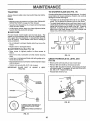
Remove drain plug.
FIG. 21
•
,
•
•
_
Keep battery and terminals clean.
Keep battery bolts tight.
Keep vent caps tight and small vent holes in caps open.
Recharge at 6 amperes for 1 hour.
i
OIL DRAIN PLUG
TO CLEAN BAq-FERY AND TERMINALS Corrosion and dirt on the battery and terminals can cause
the battery to "leak" power.
.,=
• Remove terminal guard.
• Disconnect BLACK battery cable first then RED battery
cable and remove battery from tractor.
, Wash batt3ry with solution of four tablespoons of baking
soda to one gallon of water. Be careful not to get the soda
solution into the ceils.
,,
°|1
FIG, 23
• After ell has drained completely, replace oildrain plug and
tighten securely.
• Rinse the battery with plain water and dry.
• Clean terminals and battery cable ends with wire brush
until bright.
• Refill engine with oil through oil filler tube. Pour slowly.
Do not overfill. For approximate capacity see PRODUCT
SPECIFICATIONS" on page 3 of this manual.
• Use gauge on dipstick for checking level Be sure dipstick
cap is in all the way for accurate reading. Keep oil at
"FULL" line on dipstick.
• Coat terminals with grease or petroleum jelly.
• Reinstall battery (See "INSTALL BATTERY" in the Assembly section of this manual)_
RECOMMENDED SAE VISCOSITY GRADES
ENGINE
LUBRICATION
Change the oil after the first two hours of operation and
every 100 hours thereafter or at least once a year if the tractor is not used for 100 hours in one year.
°F -20 °
°C -29°
Check the crankcase oil level before starting the engine and
after each five (5) hours of continuous use, Add SAE 30W
motor oil or equivalenL Tighten oil fill cap/dipstick securely
each time you check the oil level. SAE 5W-30 motor oil may
be used to make starting easier in areas where temperature
is consistently 32 ° F or lower.
0°
-18 °
32 °
0°
FIG. 24
TO CHANGE ENGINE OIL (See FIGS. 22, 23 and 24)
Determine temperature range expected before oil change,
All oil must meet API service classification SD, SE or SF_
• Be sure vehicle is on level surface,
• Oil will drain more freely when warm.
• Catch oil tn a suitable container.
17
60 °
16°
80°
27"
100°
38 °
MAINTENANCE
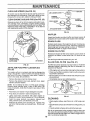
CLEAN
AIR SCREEN
(See
FIG. 25)
Air screen must be kept free of dirt and chaff to prevent engine damage from overheating. Clean with a brush or compressed air to remove dirt, stubborn dried gum fibers.
CLEAN
ENGINE
COOLING
FINS
(See FIG.
25)
Remove any dust, dirt or oil from engine cooling fins to prevent damage fi'om overheating. Engine blower housing
must be removed Remove side panels and hood (See "TO
REMOVE HOOD AND GRILL ASSEMBLY" in the Service
and Adjustments section of this manual.
FIG. 26
MUFFLER
Inspect and replace corroded muffler and spark arrester (if
equipped) as it could create a fire hazard and/or damage
SPARK
PLUGS
Replace spark plugs at the beginning of each mowing season or after every 100 hours of use, whichever comes first,
Spark plug type and gap setting is shown in "PRODUCT
SPECIFICATIONS" on page 3 of this manual,
ENGINE
OIL
FILTER
Replace the engine oil filter every season or every other oil
change if the tractor' is used more than 100 hours in one
year.
COOLING FINS
UNDER HOUSING
(BOTH SIDES)
See the Engine Manual packed with your unit=
AIR SCREEN
IN-LINE
FIG_ 25
AIR FILTER FOAM PRE-CLEANER
FIG. 26)
FUEL
FILTER
(See
FIG. 27)
Fuel filter should be replaced once each season, If fuel filter
becomes clogged, obstructing fuel flow to carburetor, replacement is required,
(See
• With engine cool, remove filter and plug fuel line sections.
° Place new fuel filter in position in fuel line with arrow pointing towards carburetor.
° Be sure there are no fuel line leaks and clamps are properly positioned.
Immediately wipe up any spilled gasoline.
Your engine will not run properly and may be damaged by
using a dirty air filter. Clean the foam pre-cleaner element
after every 25 hours of operation, more often if tractor is
used in very dusty, dirty conditions.
• Remove the wing nut and air cleaner cover,
• Remove the element cover seal, element cover, paper
element, and pre-cleaner.
CLAMP
NOTE: Do not attempt to clean or oil the paper cartridge,
Replace paper cartridge once a year or after every 100
hours of operation, more often if used in very dusty or dirty
conditions=
• Wash foam pre-cleaner
in liquid detergent and water.
FUEL FILTER
• Wrap foam pre-cleaner in cloth and squeeze dry.
• Lightly coat foam pre-cleaner with clean engine oil.
Squeeze in towel to remove excess oil. Do not saturate,
• Install the paper element, pre-cleaner
(cleaned and
oiled), element cover, and element cover seal.
• Install the air cleaner cover and wing nuL Tighten wing
nut 1/2 to 1 full turn after nut contacts cover Do not overtighten.
FIG, 27
CLEANING
, Clean engine, battery, seat, finish, etc. of all foreign matter.
• Keep finished surfaces and wheels free of all gasoline, oil,
etc.
• Protect painted surfaces with automotive type wax,
We do not recommend using a garden hose to clean your
unit unless the electrical system, muffler, air filter and carburetor are covered to keep water out, Water in engine can result in a shortened engine life,
18
,,
$EnvucE
i i,
i i,i
ADJUSTMENTS
AN
,i
CAUTION:
BEFORE PERFORMING
ANY SERVICE OR ADJUSTMENTS:
Depress clutch/brake
pedal fully and set parking brake.
Place gearshift lever In "NEUTRAL" position.
Place attachment clutch In "DISENGAGED"
position.
Turn Ignition key "OFF" and remove key.
Make sure the blades and all moving parts have completely stopped.
Disconnect spark plug wire from spark plug and place wire where it cannot come in contact with
plug.
H,r
i
TRACTOR
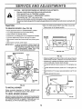
TO REMOVE
MOWER
,
ADJUSTMENT
,
(See FIGS, 29 and 30)
* Raise mower to its highest position.
(See FIG. 28)
Place attachment clutch in "DISENGAGED" position_
Turn height adjustment knob to lowest setting.
Lower mower to its lowest position,
Pull the four (4) release pins out of suspension brackets,
Pull back attachment lift lever and lock into place,
Slide mower forward and remove belt from primary mandrel,
• Slide mower out from under tractor,
IMPORTANT:
H
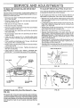
SIDE-TO-SIDE
BOTTOM
OF CURL
BoTroM
OF CURL
IF AN ATTACHMENT OTHER THAN THE
MOWER DECK IS TO BE MOUNTED ON
THE TRACTOR. REMOVE THE L.H, AND
R,H. SUSPENSION
ARMS AND THE
FRONT SUSPENSION BRACKET,
DEPTH ADJUSTMENT
_"_
GROUND LINE
]
KNOB
SUSPEN_
BELT
,
s,oN -. ,,
/
/
/
FIG. 29
• Measure height from bottom of deck curlto ground level at
front corners of mower, Distance "A" should be the same,
SUSPEN ,
A.M
I
• If distance "A" needs to be changed, snap out access hole
cover on left side of tractor above footrest,
• To raise left side of mower, loosen nut "B" and tighten nut
_C
.ONT
,
I_,
• To lower left side of mower, loosen nut"C" and tighten nut
liB'l
*
• When distance "A" is equal, securely tighten nuts "B" and
• Replace access hole cover,
ADJUSTMENT
_"
_]/
RELEASE
/
PIN
J
ROD
FIG. 28
TO INSTALL
MOWER
Follow procedure described in "INSTALL MOWER AND
DRIVE BELT'in Assembly section of this manual
r
TO LEVEL
MOWER
®
NUT "C"
HOUSING
\
Adjust the mower while tractor is parked on level ground or
driveway. Make sure tires are properly inflated (See"PRODUCT SPECIFICATIONS" on page 3 !. If tires are over or un_
derinflated, you will not properly adjust your mower.
NUT "B"
FIG. 30
19
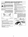
S:RVmCI5 AND .ADJUSTMENTS
FRONT-TO-BACK
ADJUSTMENT(See
FIGS
31and 32)
TO ADJUST
MOWER
DRIVE BELT
FIG. 33)
• Lower mower with attachment lift control.
To obtain the best cutting results, the mower housing should
be adjusted so the back is approximately 7/8" to 1-1/8"
higher than the front when the mower is in its highest position
(See
° Check dimension "A" on idler bracket assembly as shown.
If dimension is 1/4" or less, belt should be adjusted.
• Pull tension pulley lever forward to loosen belt.
Measure distance"D" from ground lineto bottom of deck curl
at centerline of left and right blade mandrels
, Remove idler pulley and reassemble in "NEW" pulley position hole. Tighten securely.
• Push tension pulley lever rearward into operating position.
• Check belt for proper position in all pulley grooves.
to11,0
/////7"?_772////////////////////////////
NOTE: When installing a new replacement mower drive
belt, idler pulley must be moved back to "ORIGINAL" pulley
_osition.
q
CLUTCH
PULLEY
MOWER
DRIVE
BELT
FIG. 31
PULLEY
• To raise rear of mower, loosen nut "E" on both rear suspension arms Screw both nuts "F" on both rear suspension arms an equal number of turns,
• When distance "D" is 7/8" to 1-1/8" higher at rear than
front, retighten nuts "E"
TENSION
PULLEY
IDLER
PULLEY
IDLER
BRACKET
ASSEMBLY
NUT "E"
NEW
PULLEY
POSITION
PULL FORWARD
TO LOOSEN BELT
FOR EASIER
BELT INSTALLATION
ORIGINAL
PULLEY
POSITION
FIG. 33
NUT"E"
TO REPLACE
SUSPENSION
ARMS
IMPORTANT:
DRIVE
BELT
Reverse procedure and install new belt as described in
"DRIVE BELT INSTALLATION" in the assembly section of
this manual.
FIG. 32
• Recheck side-to-side
MOWER
NOTE: If old mower drive belt was adjusted, idler pulley
must be moved back to "ORIGINAL" position when installing
a new belt.
adjustment.
WHEN ADJUSTING REAR SUSPENSION
ARMS,
ALWAYS
ADJUST
BOTH
EQUALLY SO MOWER
WILL STAY
LEVEL SIDE-TO-SIDE.
2O
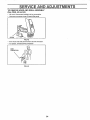
SERVICE AND ADJUSTMENTS
TO REPLACE
MOWER
BLADE
DRIVE
BELT
TO ADJUST
(See FIG. 34 )
BRAKE
(See
FIGS.
35 and
Your unit is equipped with an adjustable brake system which
is mounted on the left side of the transaxle
Park the tractor on level surface. Engage parking brake. For
assistance, there is a belt installation guide decal on the underside of mower belt cover,
If unit requires more than six (6) feet stopping distance at
high speed in highest gear, then brake must be adjusted
• Remove mower (See "TO REMOVE MOWER" in this section of this manual).
° Remove screws and idler arm nut securing mower belt
cover and remove cover
• Remove four (4) hex washer head tapping screws from
shift cover plate located on top of tractor frame, Remove
the cover plate.
• Loosen am nut (A) on brake rod (B) at clevis (C) (Fig 36)
If you find it difficult to loosen am nut (A), remove cover
plate in L,H. frame ra L
• Rotate brake rod (B) counterclockwise, turning brake rod
out of clevis (C) four (4) to six (6) turns
. Roll belt over the top of the R.H mandrel.
. Pull belt off all other mandrels.
. Remove any dirt and grass which may have accumulated
around mandrels or idler arm.
• Check deck idler arm assembly and flat idler to see that
they rotate freely.
• Be sure spring in deck idler arm assembly and on bolt in
mower housing
° Install new belt in groove of LH mandrel pulley, lower
groove of center mandrel pulley and around flat idler as
shown.
• Start tractor with transaxle in "N" (neutral) position,
• Depress clutch/brake pedal to the point where the belt
stops moving, Hold clutch/brake pedal in position by engaging parking brake. If belt begins to move after engaging parking brake, depress clutch/brake pedal to next
notch on parking brake_
. Shut engine off. Rotate brake rod (B) clockwise by hand,
turning brake rod into clevis (C) until tight Tighten jam nut
(A) on brake rod (B) at clevis (C).
° Reinstall shift cover plate and four (4) mounting screws If
cover plate in L.H, rail was removed it should be replaced
° From a position at discharge end of mower, roll idler belt
into groove of R.H mandrel pulley,
• Rotate center mandrel pulley by hand to make sure belt is
in grooves properly.
• Reassemble top cover to deck. Tighten all screws and
idler arm nut securely.
° Install mower to tractor (See "INSTALL MOWER AND
DRIVE BELT" in the assembly section of this manual),
SHIFT COVER PLATE
CENTRAL
MANDREL
PULLEY
FLAT IDLER
O
FIG. 35
L.H. MANDREL
PULLEY
R,H. MANDREL
PULLEY
/
FIG. 34
POWER TAKE
FIG. 33)
OFF (CLUTCH
PULLEY
36)
FIG. 36
- See
The power take-off clutch should provide years of service.
The clutch incorporates a built in brake that stops the pulley
almost immediately, Eventually, the internal brake will wear
so the mower blades will not stop as recommended. Ad ustment should be made by your nearest Author zed Serv ce
Center.
21
$E
CE AN
TO REPLACE MOTION
FIGS. 37 and 38)
DRIVE
ADJUSTMENTS
BELT (See
FLATIDLER
CLUTCHPULLEY
Parkthetractoronlevelsurface_
Engageparkingbrake.
For
ease of service there is a t2eltinstallation guide decal on bottom side of left footresLI
tt is not necessary to remove
mower.
BELT REMOVAL• Raise hood and disconnect negative ground battery cable.
"V" IDLER
° Set parking brake (to get belt slack)_
• Loosen (do not remove) two (2) engine pulley belt guide
bolts and swivel R.H side of belt guide up_ Tighten L.H
bolt to hold belt guide in position.
• Roll belt off engine pulley.
• Roll belt off "V" idler, flat idler and clutching idler pulleys.
, Pullbeltoffclutchpulley-betweenpulleyandframeo
Pull
belt off transaxle pulley.
BELT INSTALLATION
TO ADJUST
CLUTCHING
IDLER
TRANSAXLE
FIG. 38
STEERING
WHEEL
PULLEY
ALIGNMENT
If steering wheel crossbars are not horizontal (left to right)
when wheels are positioned straight forward, remove steering wheel and reassemble per instructions in the Assembly
section of this manual
FRONT WHEEL
-
TOE-IN/CAMBER
The front wheel toe-in and camber are not adjustable on
your unit. If darnage has occurred to affect the front wheel
tom-in or camber, corrtact your nearest authorized service
center.
° Push belt down from engine pulley area. Place back (flat)
side of belt on flat idler (flat idler is next to frame).
° Place belt on clutching idler and over clutch pulley. "V"
(narrow) part of belt should engage clutch pulley.
• Place belt around transaxle pulley. "V"partofbeltshould
engage transaxie pulley.
° Make sure "V" part of belt engages "V" idler.
• Roll belt over engine pulley
° Loosen L.H. engine pulley belt guide bolt and swivel belt
guide on to R.H. bolt. Tighten L.H. and R.H. bolts securely.
° Release parking brake.
IMPORTANT:
CHECK BRAKE ADJUSTMENT.
TO REMOVE
WHEEL
FOR REPAIRS
FRONT WHEEL (See FIG. 39) ° Block up axle securely.
• Remove hub cap, retaining ring and washers to allow
wheel removal.
• Repair tire and reassemble.
• Replace washers and snap retaining ring securely in axle
groove_
• Replace hub cap°
WASHERS
RETAINING
RING
LH, BOLT
O
r-j
ENGINEPULL__
f
R.H_BOLT
________.B,ELTGUIDE
FIG. 39
FIG. 37
REAR WHEEL" Block rear axle securely.
• Remove five (5) hub bolts to allow wheel removal.
• Repair tire and reassemble.
Replace and tighten hub
bolts and hub cap securely.
22
SERVICE AND ADJUSTMENTS
TO START ENGINE
(See FIG, 40)
WITH A WEAK
BATTERY
TO REPLACE
Replace with 30 amp automotive-type
plug-in fuse
fuse holder is located behind the dash.
i i,
CAUTION:
Lead-acid batteries generate
explosive gases. Keep sparks, flame and
smoking materials away from batterles. I
Always wear eye protection when around
batteries.
,,,
TO REPLACE
"POSITIVE"
"NEGATIVE"
BULB
• Pull bulb holder out of the hole in the backside of the grill,
• Replace bulb in holder and push bulb holder securely
back into the hole in the backside of the grill
• Close hoo&
TO ADJUST
ATTACHMENT
LIFT
SPRING
(See FIG, 41)
YOUR UNIT IS EQUIPPED WITH A 12
VOLT NEGATIVE GROUNDED SYSTEM.
THE OTHER VEHICLE MUST ALSO BE A
12 VOLT NEGATIVE GROUNDED SYSTEM. DO NOT USE YOUR TRACTOR
BATTERYTO STARTOTHER VEHICLES.
(+)
HEADLIGHT
The
• Raise hood,
If your battery is too weak to start the engine, it should be recharged. If' jumper cables' are used for emergency starting,
follow this procedure:
IMPORTANT:
FUSE
• While holding spring bushing with wrench, loosen jam nut
• Turn adjustment bolt clockwise to extend spring and reduce lift effort (for heavier attachments).
• Turn adjustment bolt counterclockwise (for lighter attachments).
• Retighten jam nut against spring bushing.
IMPORTANT:
DO NOT ADJUST
FOR MAXIMUM
SPRING TENSION WHEN USING LIGHT
ATTACHMENTS
SUCH AS A MOWER.
ADJUST LIFT LEVER SPRING TO AID IN
LIFTING ATTACHMENT. DO NOT OVERPOWER SPRING. WHEN REMOVING
ATTACHMENT,
ALWAYS ADJUST TO
SPRING TENSION TO ITS LOWEST POSITION.
(-)
ADJUSTMENT
SPRING
BUSHING
FIG. 40
ATTACHMENT
LIFT SPRING
TO ATTACH JUMPER CABLES
• Connect each end of the RED cable to the POSITIVE (+)
terminal of each battery, taking care not to short against
chassis.
• Connect one end of the BLACK cable to the NEGATIVE
(-) terminal of fully charged battery.
• Connect the other end of the BLACK cable to engine block
or a good chassis ground, away from fuel tank and battery,
JAM NUT
TO REMOVE CABLES, REVERSE ORDER
FIG, 41
• BLACK cable first from left side of chassis and fully
charged battery.
• RED cable last from both batteries.
23
SERVUCE AN
TO REMOVE HOOD AND GRILL
(See FIGS. 42 and 43)
ADJUSTMENTS
ASSEMBLY
• Lift hood Disconnect headlight wiring connection_
• Unscrew one screw at rear of each side panel.
SCREW
_
FIG. 42
• Pivot hood and side panel forward and lift off tractor.
* To replace, reverse above procedure.
aC
FIG, 43
24
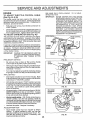
SERVUCE AND ADJUSTMENTS
ENGINE
TO ADJUST
THROTTLE
(See Fig. 44 & 45)
CONTROL
High speed stop is factory adjusted
Do not adjust damage may resulL
IMPORTANT:
NEVER TAMPER WITH THE ENGINE
GOVERNOR, WHICH IS FACTORY SET
FOR PROPER ENGINE SPEED. OVERSPEEDING THE ENGINE ABOVE THE
FACTORY HIGH SPEED SETTING CAN
BE DANGEROUS. IF YOU THINKTHE
ENGINE-GOVERNED
HIGH SPEED
NEEDS ADJUSTING, CONTACT YOUR
NEAREST
AUTHORIZED
SERVICE
CENTER, WHICH HAS PROPER EQUIP°
MENTAND EXPERIENCETO MAKEANY
NECESSARY ADJUSTMENTS
CABLE
The throttle control has been preset at the factory and
ad ustment should not be necessary. Check adjustment as
described be ow before loosening cable. If adjustment is
necessary, proceed as follows:
With engine not running, move throttle control lever to
"FAST" position.
Check that speed control lever is against stop screw. If
it is not, loosen clamp screw and pull throttle cable until
lever is against screw Tighten clamp screw securely,
TO ADJUST
CARBURETOR
(See Fig. 46)
The carburetor has been preset at the factory and adjustment should not be necessary
However, minor adjustment may be required to compensate for differences in fuel,
temperature, altitude or load If the carburetor does need
adjustment, proceed as follows:
LEVER
In general turning the adjusting needles in (clockwise) decreases the supply of fuel to the engine giving a leaner fuel/
air mixture. Turning the ad usting needles out (counterclockwise) increases the supply of fuel to the engine giving
a richer fuel/air mixture.
IMPORTANT:
THROTTLE
CABLE
DAMAGE TO THE NEEDLES AND THE
SEATS IN CARBURETOR MAY RESULT
IF NEEDLES ARE TURNED IN TOO
TIGHT,
PRELIMINARY SETTING -
FIG, 44
STOP
SCREW
Be sure you have a clean air filter and the throttle
control cable is adjusted properly (see above).
With engine off turn idle fuel adjusting needle In (clockwise) closing it finger tight and then turn out (counterclockwise) 1-1/4 turns,
Turn main fuel adjusting needle In (clockwise) closing
finger tight and then turn out (counterclockwise) 1 turn.
FINAL SETTING -
CONTROL
LEVER
Start engine and allow to warm for five minutes. Make
final ad ustments with engine running and shift/motion
control lever in ' NEUTRAL position.
With throttle control lever in "FAST" position, turn main
fuel ad usting needle In (clockwise) until engine begins
to d e then turn out (counterclockw se) unt engine
runs rough_ Turn needle to a point midway between
those two positions.
FIG. 45
IDLE SPEED
ADJUSTING
Idle speed setting - With throttle control lever in "SLOW"
position, engine should idle at 1200 RPM. If engine
idles too slow or fast, turn idle speed ad usting screw in
or out unt correct die is attained.
NEEDLE
Idle fuel needle settina - With throttle control lever in
"SLOW" position, turn idle fuel adjusting needle In
(clockwise) until engine begins to die and then turn out
(counterclockwise) until engine runs rough. Turn needle
to a point midway between those two position&
Recheck idle speed, Readjust if necessary.
ACCELERATION TEST
Move throttle control lever from "SLOW" to "FAST"
position_ If engine hesitates or dies, turn idle fuel
adjusting needle out (counterclockwise) 1/8 turn. Repeat test and continue to adjust, if necessary, until
engine accelerates smoothly.
FUEL
ADJUSTING
NEEDLE
FIG. 46
25
S'TORAGE
ENGINE
Immediate!y prepare your tractor for storage at the end of
the season or if the unit will not be used for' 30 days or more.
FUEL SYSTEM
CAUTION:
Never store
R
the tractor wlthJ
IMPORTANT:
gasolinemay
in the
tankan
inside
building
where_
fumes
reach
open aflame
or spark.|
Allow the engine to cool before storing In|
any enclosure,
i
TRACTOR
Remove mower from tractor for winter storage_ When
mower istobe stored for aperiod oftime cleanitthoroughly,
remove a dirt, grease, leaves, etc. Give blades and underside of housing a good coat of grease or rust preventative.
Store in a clean, dry area.
• Clean entire tractor (See "CLEANING" in the Maintenance section of this manual).
• Inspect and replace belts, if necessary (See belt replacement instructions in the Service and Adjustments section
of this manual).
• Lubricate as shown in the Maintenance section of this
IT IS IMPORTANT TO PREVENT GUM
DEPOSITS FROM FORMING IN ESSENTIAL FUEL SYSTEM PARTS SUCH AS
CARBURETOR,
FUEL FILTER, FUEL
HOSE, OR TANK DURING STORAGE.
ALSO, EXPERIENCE INDICATES THAT
ALCOHOL BLENDED FUELS (CALLED
GASOHOL OR USING ETHANOL OR
METHANOL) CAN ATTRACT MOISTURE
WHICH LEADS TO SEPARATION AND
FORMATION OF ACIDS DURING STORAGE ACIDIC GAS CAN DAMAGE THE
FUEL SYSTEM OFAN ENGINE WHILE IN
STORAGE.
° Drain the fuel tank,
• Start the engine and let it run untilthe fuel lines and carburetor are empty.
• Never use engine or carburetor cleaner products in the
fuel tank or permanent damage may occur,
• Use fresh fuel next season.
manual.
BATTERY
NOTE: Fuel stabilizer is an acceptable alternative in minimizing the formation of fuel gum deposits during storage°
Add stabilizer to gasoline in fuel tank or storage container,
Always follow the mix ratio found on stabilizer container.
Run engine at least 10 minutes after adding stabilizer to allow the stabilizer to reach the carburetor. Do not drain the
gas tank and carburetor if using fuel stabilizer
o Fully charge the battery for storage_
ENGINE
• After a period of time in storage, battery may require re.
charging.
Drain oil (with engine warm) and replace with clean' eneine
oil, (See "ENGINE" in the Maintenance section of this manual),
o Be sure that all nuts, bolts and screws are securely fastened. Inspect moving parts for damage, breakage and
wear. Replace if necessary.
• Touch up all rusted or chipped paint surfaces; sand lightly
before painting
• To help prevent corrosion and power leakage during long
periods of storage, battery Cables should be disconnected
and battery cleaned thoroughly (see "TO CLEAN BATTERY AND TERMINALS" in the Maintenance section of
this manual),
OIL
CYLINDERS
• Remove spark plug(s).
• Pour one ounce of oil through spark plug hole(s) into cylinder,
• After cleaning, leave cables disconnected and place cables where they cannot come in contact with battery terminals.
o Turn ignition key to "START" position for a few seconds to
distribute oil,
° Be sure battery drain tube is securely attached to drain in
battery tray,
° Replace with new spark plug(s).
OTHER
• Do riot store gasoline from one season to another.
• Replace your gasoline can if your can starts to rust. Rust
and/or dirt in your gasoline will cause problems.
• If possible, store your unit indoors and cover it to give protection from dust and dirt.
• Cover your unit with a suitable protective cover that does
riot retain moisture. Do not use plastic. Plastic cannot
breath which allows condensation to form and will cause
your unit to rusL
IMPORTANT:
26
NEVER COVER TRACTOR WHILE ENGINE AND EXHAUST AREAS ARE STILL
WARM.
TROUBLESHOOTUNG
POUNTS
PROBLEM
CAUSE
CORRECTION
Wilt not start
1,
1.
2.
3.
Out of fuel.
. Engine
"CHOKED"
Engine not
flooded.
4_ Bad spark plug.
properly.
4_
6.
7.
Replace
spark air
plug.
Clean/replace
filter.
Replace fuel filter_
Drain fuel tank and carburetor, refill tank
with fresh gasoline and replace fuel filter.
8. Check all wiring.
9. Contact Sears Setvice Department.
10. Contact Sears Setvice DepadmenL
Dirty fuel
air filter.
.. Dirty
filter.
7. Water in fuel.
8. Loose or damaged wiring.
9. Carburetor out of adjustment.
10. Engine valves out of adjustment.
Hard to start
.•
3r
4.
5.
6.
7.
8.
Engine ',viii not
turn over
1.
2•
3.
4.
5_
6.
7.
8.
9.
10_
1. Clean/replace air filter.
2. Replace spark plug.
3. Recharge or replace battery.
Dirty
air filter.
Badspark
plug.
Weak or dead battery.
Dirty fuel filter.
Stale or dirty fuel.
Loose or damaged wiring.
Carburetor out of adjustment.
Engine valves out of adjustmenL
Clutch/brake pedal not depressed.
Attachment clutch is engaged.
Spark plug wire is disconnected.
Weak or dead battery.
Blown fuse_
Corroded battery terminals.
Loose or damaged wiring.
Faulty ignition switch_
Faulty solenoid or starter.
Faulty operator presence switch(es).
Engine clicks but
wtl/not start
1.
2.
3.
4.
Loss of power
1. Cutting too much grass/too fast,
2, Throttle in"CHOKE" pesition_
3, Buildup of grass, leaves and trash under mower,
6.
7_
8•
9,
10.
11.
12.
13.
14.
15.
Fill fueltank.
See TO START ENGINE in Operation section.
Wait several minutes before attempting to stad.
Weak or dead battery.
Corroded battery terminals.
Loose or damaged wiring°
Faulty solenoid or stader.
Dirty oil
airlevel/didy
filter.
Low
oil
Faulty spark plug
Dirty fuel filter.
Stale or dirty fuel•
Water in fuel,
.•
6.
7.
8.
Replace
Drain fuelfuel
tankfilter.
and refill with fresh gasoline.
Check all wiring•
Contact Sears Setvice Department.
Contact Sears Setvice Department.
1•
2,
3,
4,
Depress clutch/brake pedal.
Disengage attachment clutch,
Connect wire to spark plug,
Recharge or replace battery,
, Replace
fuse, terminals,
Clean battery
7, Check all wiring•
. Check/replace
Check!replace ignitionswitch.
solenoid or starter,
101 Contact Sears Service DepartmenL
1_
2.
3.
4.
Recharge or replace battery.
Clean battery terminals.
Check allwidng_
Check/replace solenoid or starter.
1.
2•
3.
4,
5,
6,
Set in "Higher Cut" position/reduce speed.
Adjust throttle control
Clean underside of mower housing_
Clean/replace air filter.
Check oil level/change oil.
Clean and regap or change spark plug.
.• Replace
filter.
Drain fuelfuel
tank
and refill with fresh gasoline,
9. Drain fuel tank and carburetor, rsfil[tank
with fresh gasoline and replace fuel filter,
10, Connect and tighten spark plug wire.
11• Clean engine air screen/fins,
12, Clean/replace muffler.
13 Check allwiring.
=14. Contact Sears Setvice Department.
15, Contact Sears Setvice Department,
Spark plug wire loose.
Dirty engine air screen/fins.
Dirty/clogged muffler.
Loose or damaged wiring.
Carburetor out of adjustment.
Engine valves out of adjustment.
i
Excessive vibration
1. Worn, bent or loose blade.
2. Bent blade mandrel°
3. Loose/damaged part(s).
1.. Replace
Tighten blade bolt•
Replace blade.
blade mandrel.
3. Tighten loose part(s), Replace damaged pads.
27
=TF OUBLESHOO'T NG POINTS
PROBLEM
CAUSE
Engine continues
to run when operator leaves seat
with attachment
clutch engaged
1_ Faulty operator-safeLy
Poorcut-
1.
2_
3_
4_
uneven
Mower blades will
not rotate
Poorgrass
discharge
CORRECTION
presence control system.
Worn, bent or loose blade.
Mower deck not level.
Buildup of grass, leaves, and trash under mower.
Bent blade mandrel
1. Obstruction in clutch mechanism.
2. Mower drive belt out of ad ustment.
3 Worn/damaged mower dr ve be t
4 Frozen idler pulley.
5. Frozen blade mandrel.
1.
2.
3_
4.
5.
6.
7_
8_
9.
10.
Engine speed too slowo
Travel speed too fasL
Wet grass.
Mower deck not level.
Low/uneven tire air pressure.
Worn, bent or loose blade.
Buildup of grass, leaves and trash under mower,
Mower drive belt worn or out of adjustment.
Blades improperly installed,
Improper blades used.
1_ Check wiring, switches and connections, If not
corrected, contact Sears Setvice Department.
1,
2.
3_
4.
Replace blade. Tighten blade bolt.
Level mower deck.
Clean underside of mower housing.
Replace blade mandrel.
1. Remove obstruction.
.•
4.
5_
Adjust
Replacemower
mowerdrive
drivebelt.
bell
Replace idler pulley.
Replace blade mandrel.
1.
2.
3.
4.
5.
6.
7.
Place throttte control in "FAST" position.
Shift to slower speed,
Allow grass to dry before mowing.
Level mower deck.
Check tires for proper air pressure.
Replace/sharpen blade. Tighten blade boll
Clean underside of mower housing.
98. Replace/adjust
Reinstall blades mower
sharp drive
edge bell
down.
Replace with blades listed in this manual
10.
Headlight(s) not
working (if so
equipped)
1.
2.
3
4
5.
Switch is "OFF".
Bulb(s) burned out.
Faultylight switch.
Loose or damaged wiring.
Blown fuse.
1, Turn switch "ON"_
2. Replace bulb(s).
3. Check/replace light switch.
4. Check wiring and cannections_
5. Replace fuse.
Battery will not
charge
1
2.
3.
4.
Bad battery cell s).
Poor cab e connect ons.
Faulty regulator (if so equipped).
Faulty alternator,
1_
2.
3u
4.
28
Replace battery.
Check/clean al/connections.
Replace regulator.
Replace alternator.