1
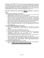
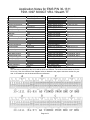
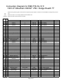
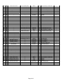
Installation Instructions for: EMS P/N 30-1311 1991-97 Mitsubishi 3000GT VR4 1991-1997 Dodge Stealth TT ,! WARNING: This installation is not for the tuning novice nor the PC illiterate! Use this system with EXTREME caution! The AEM EMS System allows for total flexibility in engine tuning. Misuse of this product can destroy your engine! If you are not well versed in engine dynamics and the tuning of management systems or are not PC literate, please do not attempt the installation. Refer the installation to a AEM trained tuning shop or call 800-423-0046 for technical assistance. You should also visit the AEM EMS Tech Forum at http://www.aempower.com NOTE: AEM holds no responsibility for any engine damage that results from the misuse of this product! This product is legal in California for racing vehicles only and should never be used on public highways. ADVANCED ENGINE MANAGEMENT INC. th 2205 126 Street Unit A Hawthorne, CA. 90250 Phone: (310) 484-2322 Fax: (310) 484-0152 Http://www.aempower.com Instruction Part Number: 10-1311 2004 Advanced Engine Management, Inc. Page 1 of 1 Congratulations! You have just purchased the finest Engine Management system for your car at any price! The AEM Engine Management System (EMS) is the result of extensive development on a wide variety of cars. Each system is engineered for the particular application. The AEM EMS differs from all others in several ways. The EMS is an all new stand alone system, which completely replaces the factory ECU and features unique Plug and Play Technology, which means that each system is configured especially for your make and model of car. There is no need to modify your factory wiring harness and in most cases your car may be returned to stock in a matter of minutes. The AEMPro software is configured to work with the factory sensors and equipment, so that there is no need for expensive or hard to find sensors, making replacement and repairs as simple as with an unmodified car. For stock and some slightly modified cars, the AEMPro software will be preprogrammed with a set of base parameters, providing a starting point for individual tuning. For more heavily modified cars, the EMS has many spare inputs and outputs allowing the elimination of separate rev-limiters, boost controllers, nitrous controllers, and fuel computers. It also includes a configurable onboard data logger capable of recording 512kb of information. Every EMS comes with all functions installed and activated, and there are no expensive options or upgrades to be performed. The installation of the AEM ECU on the 1993-1997 3000GT/Stealth uses the stock sensors and actuators. The base maps are automatically installed in the base calibrations directory in the AEMPro directory on your computer. The 91-93 and 94-97 installations use a different base map due to wiring / model feature changes. The EMS hardware is the same. We have supplied 2 different base calibrations on the CD, one for each application. You MUST upload the correct calibration to the EMS before you attempt to start the engine. 1991-1993: 1311-91-93-MAF.v1.11.cal 1994-1997: 1311-94-97-MAF.v1.11.cal Full details of the test vehicle used to generate this map can be found in the files notes section. However, while the base map is a good starting point and may save you considerable time and money, it will not replace the need to tune your specific application. It is not intended to be driven aggressively. Ignoring this can and will damage your engine. The EMS does not support the Active Exhaust found on the 91-93 models. If you still have this, it must be disconnected from the ECU (pin 102). If not disconnected, a whirring noise will be heard from the AE drive motor located in the left rear quarter panel on the car. While this causes no damage, it is quite annoying. The base maps have knock control enabled and can display or log the stock O2 sensors but lambda closed loop A/F control is not activated. The check engine light is configured as a shift light at 7000 but this value can be changed. The stock “boost” gauge is not used. Page 2 of 2 Please visit the AEM EMS Tech Forum at http://www.aempower.com/bbs and register your EMS before you start to use it. Make sure you enter your EMS serial number when you register as doing this grants access to the calibration files. We always post the most current strategy release, PC Software and base calibrations online. On the forum, you will find many helpful hints/tips to make your EMS perform it’s best. Also, we may make available EMS maps for engines running speed density, larger turbo, etc… Read and understand these instructions BEFORE attempting to install this product. 1) Removing the Stock Engine Control Unit a) Access the stock Engine Control Unit (ECU). The location of the ECU on the 3000GT/Stealth is in the center console, behind the radio. b) Carefully disconnect the wiring harness from the ECU. Avoid excessive stress or pulling on the wires, as this may damage the wiring harness. Some factory ECU’s use a bolt to retain the factory connectors, and it must be removed before the harness can be disconnected. There may be more than one connector, and they must all be removed without damage to work properly with the AEM ECU. Do not cut any of the wires in the factory wiring harness to remove them. c) Remove the fasteners securing the ECU to the car body, and set it aside. Do not destroy or discard the factory ECU, as it can be reinstalled easily for street use and troubleshooting. 2) Install the AEM Engine Management System. a) Plug the factory wiring harness into the AEM ECU, and position it so that the wires are not pulled tight or stressed. Secure it with the provided Velcro fasteners. b) Plug the comms cable into the EMS and into your PC. c) Turn your ignition on but do not attempt to start the engine. d) Upload the base calibration file (.cal) that most closely matches your vehicle’s configuration. (These files can be found in the AEMPro/Base Calibrations/Mitsubishi folder on your computer’s hard drive) e) Set the throttle range: Select the Configure drop down menu, then ECU Setup | Set Throttle Range and then follow the direction given on the screen. f) Verify the ignition timing by selecting the Configure drop down menu, then ECU Setup | Set Ignition. Use a timing light and compare the physical timing numbers to the Parameter Ignition Timing displayed. Use the Advance/Retard buttons to make the timing number match. 3) You are now ready to begin tuning your vehicle. a) Note: This calibration needs to be properly tuned and is not recommended for street use. NEVER TUNE YOUR VEHICLE WHILE DRIVING. Page 3 of 3 Application Notes for EMS P/N 30-1311 1991-1997 3000GT VR4 / Stealth TT Make: Mitsubishi/Dodge Supplied Connectors: Connector B Model: 3000GT VR4 / Stealth TT Spare Injector Drivers: Inj #7, Pin 116 Years Covered: 1991 – 1997 Spare Injector Drivers: Inj #8, Pin 6 Engine Displacement: 3.0L Spare Injector Drivers: Inj #9, Pin 83 Engine Configuration: V6 Spare Injector Drivers: Inj #10, Pin 106 Firing Order: 1-2-3-4-5-6 Spare Injector Drivers: --N/A, S/C or T/C: T/C Spare Injector Drivers: --Load Sensor Type: Karman Vortex MAF Spare Coil Drivers: Coil #4, Pin 86 Map Min: N/A Spare Coil Drivers: --Map Max: N/A Spare Coil Drivers: --# Coils: 3 Spare Coil Drivers: --Ignition driver type: 0-5V Logic Boost Solenoid: PW #2, Pin 105 How to hook up a CDI: Wire before igniter EGT #1 Location: Pin 54 # Injectors: 6 (Inj 1-6) EGT #2 Location: Pin 114 Injector Flow Rate: 370 cc/min EGT #3 Location: --Injector Resistance: 2.3 Ω EGT #4 Location: --Injection Mode: Sequential Spare 0-5V Channels: ADR15, Pin 112 Knock Sensors used: 1 Spare 0-5V Channels: ADR16, Pin 111 Lambda Sensors used: 1&2 Spare 0-5V Channels: ADR11, Pin 90 Idle Motor Type: Stepper Spare Low Side Driver: Low Side #1, Pin 109 Main Relay Control: Yes Spare Low Side Driver: Low Side #2, Pin 21 Crank Pickup Type: Hall Spare Low Side Driver: Low Side #4, Pin 9 Crank Teeth/Cycle: 6 Spare Low Side Driver: Low Side #9, Pin 22 Cam Pickup Type: Hall Check Engine Light: Low Side #10, Pin 106 Cam Teeth/Cycle: 2 Spare Switch Input: Switch #6, Pin 82 Transmissions Offered: M/T Spare Switch Input: Switch #4, Pin 7 Trans Supported: M/T Only A/C Switch Input: Switch #3 Drive Options: AWD Clutch Switch Input: --Notes: The connector numbering for the 91-93 and the 94-97 are different. The numbers listed above are for the 91-94 only. See the connector face diagram below to determine the proper connector number for your year. In all questions, use the pictures below as a reference. Page 4 of 4 Connection Diagram for EMS P/N 30-1311 1991-97 Mitsubishi 3000GT VR4 / Dodge Stealth TT PnP Means the Plug and Play system comes with this configured for proper operation of this device. Is still available for reassignment by the end user. Avail Means the function is not currently allocated and is available for use Dedicated Means the location is fixed and cant be changed 91-93 94-97 Pin # Pin # 91-93 3000 GT 94-97 3000 GT EMS P/N 30-1311 I/O 91-93 Notes 94-95 Notes 1 1 Injector 1 <--- Injector #1 Output PnP for Injector 1 <-- 2 2 Injector 3 <--- Injector #3 Output PnP for Injector 3 <-- 3 3 Injector 5 <--- Injector #5 Output PnP for Injector 5 <-- 4 4 Idle Air Control Motor <--- Idle 1 Output PnP for Idle Motor <-- 5 5 Idle Air Control Motor <--- Idle 3 6 6 EGR Solenoid Valve <--- Injector #8 7 7 Fuel Pressure Solenoid <--- Switch #4 8 8 MFI Relay (fuel pump) <--- Low Side #11 Output Dedicated - Fuel Pump <-- Output PnP for Idle Motor <-- Output Avail, Switched Ground driver <-- Input Avail, Switch input <-- 9 9 EVAP Purge Solenoid Valve <--- Low Side #4 Output Avail, Switched Ground driver <-- 10 10 Ignition Power Transistor (1-4) <--- Coil #1 Output PnP for Coil 1 <-- 11 11 Ignition Power Transistor (3-6) <--- Coil #3 Output PnP for Coil 3 12 12 MFI Relay Power IN (main) <--- Inj Pwr Input Dedicated <-- 13 13 Ground (cam/crank) <--- Ground Input Dedicated <-- 14 14 Injector 2 <--- Injector #2 Output PnP for Injector 2 <-- 15 15 Injector 4 <--- Injector #4 Output PnP for Injector 4 <-- 16 16 Injector 6 <--- Injector #6 Output PnP for Injector 6 <-- 17 17 Idle Air Control Motor <--- Idle 2 Output PnP for Idle Motor <-- 18 18 Idle Air Control Motor <--- Idle 4 Output PnP for Idle Motor <-- 19 19 Maf reset switch <--- Low Side #8 Output PnP for Maf Reset 20 20 A/C clutch slip input Rad Fan High Low Side #9 Output Avail, Switched Ground driver Rad Fan High 21 21 Fuel Pump Relay (low speed) Rad Fan Low Low Side #2 Output Avail, Switched Ground driver Rad Fan Low 22 22 Magnetic Clutch Relay <--- Low Side #6 Output PnP for A/C Compressor 23 23 Ignition Power Transistor (2-5) <--- Coil #2 24 24 Electrical Load (input) <--- Switch #3 25 25 MFI Relay Power IN (main) <--- 26 26 Ground (in) <--- 101 31 Ignition OK input Fuel Pump Relay (Low) Not Used 102 32 Active Exhaust Wastegate Solenoid PW #2 Output PnP for Boost Solenoid <-- 103 33 Active Exhaust Switch --- PW #1 Output Avail <-- 104 34 Timing Adjust Connector Active Exh / LF O2 Heater Injector #10 105 35 Wastegate Solenoid RF O2 Heater PW #2 106 36 Check Engine <--- Low Side #10 107 37 PS Press. Switch <--- Switch #5 108 38 MFI Relay (Main) <--- MAIN Relay Output Dedicated <-- 109 39 --- Boost Gauge (96-97) Low Side #1 Output Avail, Switched Ground driver <-- 110 40 --- Fuel Pressure Sol (96-97) Idle 6 111 41 Boost Gauge Boost Gauge (94-95) ADR16 Output PnP for Coil 2 <-- <-- <-<-- Input Avail, Switch input <-- Inj Pwr Input Dedicated <-- Ground Input Dedicated <-- Page 5 of 5 --- Dedicated <-- Output Avail, Switched Ground driver <-- Output PnP for Boost Solenoid <-- Output PnP for 7,000 RPM Shift Light <-- Input PnP for PS Press Output Avail Input Avail, 0-5 Volt Input, 100K pull up <-- <-<-- 112 42 Data Link Connector LR O2 Heater (96-97) ADR15 Input Avail, 0-5 Volt Input, 100K pull up 113 43 Data Link Connector RR O2 Heater (96-97) High Side #4 114 44 ABS Control <--- EGT #2 115 45 Magnetic Clutch <--- Switch #3 116 46 --- --- Injector #7 80 51 --- --- Not Used 81 52 --- Ign. Timing Adj PW #1i 82 53 --- --- Switch #6 83 54 --- --- Injector #9 Output Avail, Switched Ground driver <-- 84 55 --- --- Low Side #5 Output Avail, Switched Ground driver <-- 85 56 --- Data Link Connector High Side #3 Output Avail, Switched 12v, 1.5A max <-- 86 57 --- --- Coil #4 87 58 --- Ignition OK input Not Used 88 59 --- A/C clutch slip input Low Side #12 Output Avail, Switched Ground driver <-- 89 60 --- Right O2 Sensor Rear (Cal) Injector #9 Output Avail, Switched Ground driver <-- 90 61 --- --- ADR11 91 62 --- Data Link Connector FM 51 71 Starter Signal <--- SW Input Dedicated <-- 52 72 Intake Air Temp Sensor <--- AIT Input Dedicated <-- 53 73 EGR Temp Sensor Right O2 Rear (96-97) MAP Input Avail, default 0-5v MAP sensor in <-- 54 74 --- Manifold Diff Press (96-97) EGT #1 Input Avail, RTD Temp <-- 55 75 Right Bank O2 Sensor <--- Lambda #2 Input PnP for Lambda 2 <-- 56 76 Left Bank O2 Sensor <--- Lambda #1 Input PnP for Lambda 1 <-- 57 77 --- --- Knock #2 Input Avail, Knock sensor input <-- 58 78 Knock Sensor <--- Knock #1 Input PnP for Knock Sensor <-- 59 79 --- Left O2 Sensor Rear (Cal) MAF Input Avail, default 0-5v MAF sensor in <-- 60 80 Battery Back Up <--- Perm 12V Input Dedicated <-- 61 81 5v ref <--- 62 82 Ignition Switch <--- Ignition Switch Input Dedicated <-- 63 83 Engine Coolant Temp. Sensor <--- Coolant Input Dedicated <-- 64 84 Throttle Position Sensor <--- TPS Input Dedicated <-- 65 85 Atmospheric Press. Sensor <--- AbPress Input Dedicated <-- 66 86 Vehicle Speed Sensor <--- Vehicle Speed Input Dedicated <-- 67 87 Throttle Position Switch <--- ADR11 Input Avail, 0-5 Volt Input, 100K pull up <-- 68 88 Camshaft Position Sensor <--- Cam Input Dedicated <-- 69 89 Crankshaft Position Sensor <--- Crank Input Dedicated <-- 70 90 Volume Air Flow Sensor <--- Spare Speed Input PnP for Karman MAF <-- 71 91 Ground <--- Ground Input Dedicated <-- 72 92 Sensor Ground <--- Sensor Ground Output Dedicated <-- Output Avail, Switched 12v, 1.5A max <-- Input Avail, RTD Temp <-- Input PnP for AC On Request <-- Output Avail, Switched Ground driver --- Dedicated Output Avail Input Avail, Switch input Output Avail --- Dedicated Input Avail, 0-5 Volt Input, 100K pull up Output Avail, Switched Ground driver 5 Volt Reference Output Dedicated Page 6 of 6 <-- <-- <-<-<-- <-<-- <-<-- <--