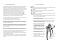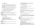
1
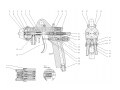
Das WALTHER PILOTProgramm
The WALTHER PILOT
Programme
• Hand-Spritzpistolen
• Automatik-Spritzpistolen
• Niederdruck-Spritzpistolen
(System HVLP)
• ZweikomponentenSpritzpistolen
• Materialdruckbehälter
• Drucklose Behälter
• Rührwerk-Systeme
• Airless-Geräte und
Flüssigkeitspumpen
• Materialumlaufsysteme
• Kombinierte Spritz- und
Trockenboxen
• Absaugsysteme mit
Trockenabscheidung
• Absaugsysteme mit
Nassabscheidung
• Trockner
• Zuluft-Systeme
• Atemschutzsysteme und
Zubehör
• Hand-Held Spray Guns
• Automatic Spray Guns
• Low Pressure Spray Guns
(System HVLP)
• Two-Component Spray Guns
WALTHER PILOT
Betriebsanleitung / Operating Instructions
Zweikomponenten-Spritzpistole
Two-Component-Spray Gun
• Material Pressure Tanks
• Nonpressurized Tanks
• Agitator Systems
• Airless Equipment and Transfer
Pumps
• Material Circulation Systems
• Combined Spraying and Drying
Booths
• Dry Back Overspray Extraction
Systems
• Wet Back Overspray Extraction
Systems
• Dryers
• Ventilation Systems
• Protective Respiratory Systems
and Accessory Items
PILOT Misch-N
Typ / Type
24 320
REV. 03/10
WALTHER Spritz- und Lackiersysteme
Kärntner Str. 18-30
42327 Wuppertal Germany
Telefon: 0202 / 787-0
Telefax: 0202 / 787-217
www.walther-pilot.de • Email: [email protected]
EG-Konformitätserklärung
Declaration of CE-Conformity
Wir, der Gerätehersteller, erklären in alleiniger Verantwortung, dass das Produkt in der
untenstehenden Beschreibung den einschlägigen grundlegenden Sicherheits- und
Gesundheitsanforderungen entspricht. Bei einer nicht mit uns abgestimmten Änderung an dem
Gerät oder bei einer unsachgemäßen Verwendung verliert diese Erklärung ihre Gültigkeit.
We, the manufacturers of the equipment, hereby declare under our sole responsibility that
the product(s) described below conform to the essential safety requirements. This declaration will
be rendered invalid if any changes are made to the equipment without prior consultation with us.
Hersteller
WALTHER Spritz- und Lackiersysteme GmbH
Kärntner Str. 18 - 30
D - 42327 Wuppertal
Tel.: +49(0)202 / 787 - 0
Fax: +49(0)202 / 787 - 217
www.walther-pilot.de • e-mail: [email protected]
Typenbezeichnung
Zwei-Komponenten Handspritzpistole
PILOT Misch-N
Verwendungszweck
Type Designation
Two-Component Manual spray Gun
PILOT Misch-N
Intended purpose
Verarbeitung spritzbarer Materialien
24 320
Processing of sprayable media
Applied Standards and Directives
EU-Mechanical Engineering Directives 2006 / 42 / EC
94 / 9 EC (ATEX Directives)
DIN EN ISO 12100-1
DIN EN ISO 12100-2
DIN EN 1953
EN 1127-1
DIN EN 13463-1
EG-Maschinenrichtlinien 2006 / 42 / EG
94 / 9 EG (ATEX Richtlinien)
DIN EN ISO 12100 Teil 1
DIN EN ISO 12100 Teil 2
DIN EN 1953
DIN EN 1127-1
DIN EN 13463-1
Specification according 94 / 9 / EC
Spezifikation im Sinne der Richtlinie 94 / 9 / EG
Gerätebezeichnung
WALTHER Spritz- und Lackiersysteme GmbH
Kärntner Str. 18 - 30
D - 42327 Wuppertal
Tel.: +49(0)202 / 787 - 0
Fax: +49(0)202 / 787 - 217
www.walther-pilot.de • e-mail: [email protected]
24 320
Angewandte Normen und Richtlinien
Kategorie 2
Manufacturer
II 2 G c T 6
Tech.File,Ref.:
2409
Bevollmächtigt mit der Zusammenstellung der technischen Unterlagen:
Nico Kowalski, WALTHER Spritz- und Lackiersysteme GmbH, Kärntner Str. 18 - 30
D- 42327 Wuppertal
Besondere Hinweise :
Das Produkt ist zum Einbau in ein anderes Gerät bestimmt. Die Inbetriebnahme ist so lange
untersagt, bis die Konformität des Endproduktes mit der Richtlinie 2006 / 42 / EG festgestellt ist.
Wuppertal,den 07. Juli 2003
i.V.
Name: Torsten Bröker
Stellung im Betrieb: Leiter der Konstruktion und Entwicklung
Diese Erklärung ist keine Zusicherung von Eigenschaften im Sinne der Produkthaftung. Die Sicherheitshinweise
der Produktdokumentation sind zu beachten.
Category 2
Part marking
II 2 G c T 6
Tech.File,Ref.:
2409
Authorized with the compilation of the technical file:
Nico Kowalski, WALTHER Spritz- und Lackiersysteme GmbH, Kärntner Str. 18 - 30
D- 42327 Wuppertal
Special remarks :
The named product is intended for installation in other equipment. Commissioning is prohibited
until such time as the end product has been proved to conform to the provision of the Directives
2006 / 42 / EC.
Wuppertal, the 7th of July 2003
i.V.
Name: Torsten Bröker
Position: Manager, Design and Development
This Declaration does not give assurance of properties in the sense of product liability. The safety instructions
provided in the product documentation must be observed at all times.
Listing of Replacement Parts
Item
Contents
Article No.
Discription
1
2
3
4
V
V
V
V
24 329 05 000
24 329 04 . . 0*
09 101 75 000
24 329 01 . . 3*
Air cap nut
Air cap
Air cap seal
Material nozzle
5
V 11 306 21 . . 3*
Material needle
6
7
V 24 321 01 000
V 10 361 08 000
Gun body
Needle packing
V
V
V
V
V
V
V
V
V
V
V
V
V
V
V
V
V
V
V
V
V
V
V
V
V
Needle gland nut
Driving bushing
Counter-screw
Wide jet regulator
Lever shank screw
Distance bushing
Lever screw
Double nipple
Cap nut
Hose grommet
Double nipple
Cap nut
Hose grommet
Spring bushing
Needle spring
Counter-screw
Valve housing
Valve spring
Valve cone
Valve shaft
Packing
Valve compression gland
Double nipple
Seal
Trigger
8
9
10
11
12
13
14
15
16
17
18
19
20
21
22
23
24
25
26
27
28
29
30
31
32
01 101 01 000
10 306 06 000
10 306 08 000
10 902 00 000
24 321 05 000
24 321 06 000
10 301 09 000
24 321 03 000
00 101 03 000
00 101 02 003
24 381 05 000
00 101 12 005
24 321 09 003
24 306 05 000
10 306 04 000
20 001 06 000
10 904 04 000
10 304 03 000
10 904 02 000
10 304 01 000
09 101 02 020
10 901 06 000
00 101 01 000
09 101 76 010
24 321 04 000
The wearing parts are shown in boldface print in the list of the replacement parts. We
recommand that wearing parts are held on stock.
Nozzle sets constist of air control head, material nozzle and material needle.
Nozzle sets No.: V 15 019 02 . . 3
* Please quote the respective sizes when ordering replacements.
(Nozzle sizes optional:0,5 • 0,8 • 1,0 • 1,2 • 1,5 • 1,8 • 2,0 • 2,5 mm ø)
1
General Information
1.1
1.2
1.3
Identification of Model Version
Normal Use
Improper Use
2
Technical Description
3
Safety Instructions
4
Connection of Input Lines
5
Operation
5.1
5.2
5.3
5.4
5.5
Safety Instructions
Requirements at the Start and Finish of Operation
Spray Pattern Test
Spray Pattern Adjustment
Retooling the Spray Gun / Repairs
6
Cleaning
6.1
6.2
6.3
Safety Warnings
General Cleaning Procedure
Routine Cleaning
7
Troubleshooting
8
Disposal of Cleaning and Servicing Substances
9
Specifications
1
1.1
General Information
Identification of Model Version
Model:
Two-Component Spray Gun PILOT Misch-N
Type:
Pilot Misch-M
Manufacturer:
WALTHER Spritz- und Lackiersysteme GmbH
Kärntner Straße 18-30
D-42327 Wuppertal
Tel: +49 202 787-0
Fax:+49 202 787-217
www.walther-pilot.de • Email:[email protected]
1.2
24 320
Normal Use
The hand-held spray gun PILOT Misch-N is a two-component manual spray gun for
materials with a short pot life.
The hand-held spray gun PILOT Misch-N is designed exclusively for use with sprayable media, including water-based and aggressive media, such as:
• paints and laquers
• greases, oils and corrosion preventives
• ceramic glazes
• pickling solutions
Since all wetted parts are made of stainless steel, water-based media may be used
as well.
If you have any questions, please contact WALTHER Spritz- und Lackiersysteme
GmbH, Wuppertal.
Sprayable material should only be applied to work pieces or similar objects.
The temperature of the material to be sprayed should at no time exceed 43° C.
The term Normal Use also implies that any and all safety warnings and instructions
laid down in these operating instructions have been read, understood and are duly
complied with.
This equipment complies with the explosion protection requirements of Directive
94/9/EC (ATEX) for the explosion group, equipment category and temperature class
indicated on the type plate. When using the equipment, the requirements specified in
these Operating Instructions must be observed at all times.
The technical data indicated on the equipment rating plates and the specifications in
the chapter "Technical Data" must be complied with at all times and must not be
exceeded. An overloading of the equipment must be ruled out.
1
The equipment may be used in potentially explosive atmospheres only with
the authorisation of the relevant supervisory authority.
The relevant supervisory authority or the operator of the equipment are
responsible for determining the explosion hazard (zone classification).
The operator must check and ensure that all technical data and the marking of
the equipment in accordance with ATEX are compliant with the necessary
requirements.
The operator must provide corresponding safety measures for all applications
in which the breakdown of the equipment might lead to danger to persons.
If any irregularities are observed while the equipment is in operation, the
equipment must be put out of operation immediately and WALTHER Spritz-und
Lackiersysteme must be consulted.
Grounding / Equipotential Bonding
Measures must be taken to ensure that the spray gun is sufficiently grounded
(earthed) by means of a conductive air hose (maximum resistance 106 ).
1.3
Improper Use
The spray gun must not be used for purposes other than those laid down in
the above section 1.2 Normal Use.
Any other form of use is prohibited.
Improper use includes
• the spraying of material on persons and animals
• the use of liquid nitrogen.
2
Technical Description
The model Pilot Misch-N feeds both material components to the separate connections. Mixing takes place only in the spray jet. The mixing ratio and the
material flow rate are determined by the different nozzle sizes and the material
pressure.
When the trigger (item 32) is actuated, the valve cone (item 26) opens first of
all (pre-air), after which the material supply is opened as the material needle
(item 5) is pulled back. Closing takes place in the reverse order.
The width of the spray jet can be infinitely varied by the wide jet regulator
(item 11).
2
3
General Safety Instructions
All applicable accident prevention rules and regulations as well as other recognised
industrial safety and health rules and regulations must be observed at all times.
Use the spray gun only in well-ventilated rooms. Fire, naked flames and smoking are
strictly prohibited within the working area. WARNING – during the spraying of flammable materials (e.g. lacquers, adhesives, cleaning agents, etc.), there is an
increased risk to health as well as an increased risk of explosion and fire.
Measures must be taken to ensure that the spray gun is sufficiently grounded
(earthed) by means of a conductive air hose (maximum resistance 106 ).
Before carrying out maintenance or servicing work, always ensure that the air and
material feed to the spray gun have been de-pressurised. Risk of injury!
When spraying materials, do not place your hands or other parts of the body in front
of the pressurised nozzle or the spray gun. Risk of injury!
Never point the spray gun at persons or animals. Risk of injury!
Always observe the spraying and safety instructions given by the manufacturers of
the spraying material and the cleaning agent. Aggressive and corrosive materials in
particular can be harmful to health.
Exhaust air containing particles (overspray) must be kept away from the working area
and personnel. In spite of these measures, always wear the regulation breathing
masks and protective overalls when using the gun. Airborne particles represent a
serious health hazard!
Always wear hearing protection when using the gun or when in the vicinity of a gun
that is in use. The noise level generated by the spray gun is approx. 85 dB (A).
After carrying out assembly or maintenance work, always ensure that all nuts, bolts
and screw connections have been fully tightened before the gun is used.
Use only original replacement parts, since WALTHER can only guarantee safe and
fault-free operation for original parts.
For further information on the safe use of the spray gun and the spraying materials,
please contact WALTHER Spritz- und Lackiersysteme GmbH, D-42327 Wuppertal,
Germany.
4
Connection of Input Lines
Note
Please refer to the exploded view supplied with this manual when performing the
installation steps described on the following pages.
Warning
The air pressure of the gun must not exceed 8 bar; otherwise safe operation
of the gun cannot be guaranteed.
Warning
Material and air hoses which are installed with a hose grommet must be additionally secured with a hose clamp.
1. Connect the air hoses (cleaned compressed air) to the material pressure tanks
and the air inlet (item 30)of the spray gun.
2. Fill the material pressure tanks for component A and component B with the respective material and close the lid.
3. Fasten the material inlet hose to its respective material pressure tank or the
material pressure regulator, if a pump system is used, and to the material
inlets (item 15 and 18) of the spray gun.
4. Switch on the pressurised air and adjust
the air pressure reduction valve to the
required atomizing air pressure. Adjust
the air pressure reduction valves on the
material pressure tanks to the required
pressure.
If the material is fed via a pump system
the pressure is adjusted via an adjusting
key on the material pressure control.
5. Open the material tap at the material outlet of the relevant pressure tank.
Material connection
(item 15)(R
1/4’’-1/4’’)
6. To bleed any air left left in the material
hose actuate the trigger until a uniform jet
emerges from the nozzle.
The spray gun is now ready for operation.
Material connection
(item 18)
(R 1/4’’-3/8’’)
Air supply
3
4
5
5.1
Operation
Safety Instructions
Please pay special attention to the following safety instructions when using the spray
gun!
• Be sure to wear the required respiratory protection masks and protective overalls whenever you are operating the spray gun. Airborne particles represent a
health hazard.
• Be sure to wear suitable ear protection. The spray gun produces sound levels of
approx. 83 dB (A).
• No open fires, naked lights or smoking in the working area. The spraying of readily
inflammable media is accompanied by an increased risk of fire and explosion.
5.2
Requirements at the Start and Finish of Operation
The following requirements must be met before the spray gun is operated:
• The atomizing air pressure must be available at the gun
• The material pressure must be available at the gun.
Caution
The material pressure should not exceed 8 bar. The air pressure should not exceed 8
bar. Otherwise the operational reliability of the spray gun will be impaired.
Warning
It is important to remember to relieve the spray gun of all pressures when work is terminated. Lines left under pressure may burst and the released material may injure
any persons in the vicinity.
5.3
Spray Pattern Test
Spray pattern tests should be performed whenever:
• the spray gun is taken into operation for the first time
• the spraying medium has been changed
• the spray gun was taken apart for maintenance or repair works.
The spray pattern is best tested using a workpiece sample, a sheet of metal, cardboard or paper.
Warning
Keep your hands or other parts of the body away from the spray gun nozzle under
pressure - risk of injury.
Warning
Make sure that no other people are in the spraying zone when the spray gun is started - risk of injury.
5
1. Start the gun to produce a spray pattern sample (see 5.2 Requirements
at the Start and Finish of Operation).
2. Inspect the sample and, if necessary, adjust the settings of the gun (see
5.4 Spray Pattern Adjustment).
5.4
Spray Pattern Adjustment
The spray pattern of the Pilot Misch-N can be adjusted as follows:
Adjusting the Material Flow Rate
The material flow rate is determined by the nozzle size and the material pressure.
Adjusting the Material Pressure
The material pressure can only be adjusted at the pump or the pressure tank.
Please follow the instructions and safety instructions issued by the manufacturer.
Adjusting the Flat-Jet
The width of the spray jet can be infinitely varied by the wide jet regulator
(item 11).
5.5
Retooling the Spray Gun / Repairs
Air control head, material control nozzle and needle packing, all chosen for a particular spraying material, together form a unit - the nozzle insert assembly. Always
change the complete insert assembly to maintain the desired spray finish quality.
Warning
Air and material inputs must be shut off prior to retooling - risk of injury.
Note
Please refer to the exploded view supplied with this manual when performing the
installation steps described on the following pages.
Replacement of Material Nozzle and Air Control Head
1. Unscrew the air cap nut (item 1).
2. Remove the air control head (item 2).
3. Remove the material control nozzle (item 4) from the gun body (item 6), using
wrench (width over flats 12.)
4. Remove the air cap seal (item 3) from the material nozzle.
Reassembly of the new nozzle insert and the remaining parts is performed in
reverse order. When mounting observe that the hole of the air control head exact
matches with the guide pin of the gun body. The nozzles are useable for different
application.
6
Replacement of Material Control Needle
1. Unscrew the spring bushing (Item 21).
2. Remove the spring spring (Item 22).
3. Remove the material needle (Item 4) with the driving bushing (item 9) and the
counter-screw (item 10) from the gun body. Remove the needle from the dring
bushing.
The distance between the tip of the material needle and the driving bushing should
be 78 ± 0.5 mm. Control the distance and ensure with the counter-screw.
Reassembly is performed in reverse order.
Replacement of Valve Cone
1. Unscrew the valve housing (item 24) from the gun body.
2. Remove the valve spring (item 25) and the valve cone (item 26) from the gun
body.
Reassembly is performed in reverse order.
Replacement of Defective Needle Seal Packings
1. Remove the material control needle as described in "Replacement of
Material Control Needle “.
2. Unscrew the needle packing gland (item 8) from the gun body
3. Remove the needle seal packing (item 7) from the gun body. Use a strong wire
with one end bent to form a small hook.
Reassembly of replacement parts is performed in reverse order.
Note
Prior to assembly all moveable and sliding parts should be lubricated with a non-acidic, non-resinogenic grease.
Note
The wearing parts are shown in boldface print in the list of the replacement parts.
6
6.1
Cleaning
Safety Warnings
• Prior to any service work all air and material inputs should be shut off - risk of
injury.
• Open fires, naked lights and smoking are prohibited in the working area. There
is an increased risk of fire and explosion, when spraying readily flammable
media, such as cleaning solutions.
• Follow the safety instructions issued by the manufacturer of the cleaning
media. Aggressive and caustic cleaning agents in particular represent health
hazards.
6.2
General Cleaning Procedure
The spray gun should be frequently cleaned and lubricated to ensure reliable operation and long life.
Caution
Never immerse the spray gun in solvents or other cleaning fluids as this will
impair the functional reliability and efficiency of the gun.
Caution
Do not use any hard or sharp-pointed objects when cleaning the spray gun, as
the precision-made parts can easily be damaged and are likely to affect your
spraying results.
Only use cleaning solutions recommended by the manufacturer of the spraying
material. These solutions should not contain any of the following constituents:
• halogenated hydrocarbons
(e.g. 1,1,1-trichloroethane, methylene chloride etc.)
• acids and acidic cleaning solutions
• regenerated solvents (so-called cleaning dilutions)
• paint removers.
These constituents cause chemical reactions with electroplated components
resulting in corrosion damage.
WALTHER Spritz-und Lackiersysteme is not liable for any damages resulting from
improper treatment of the gun.
The spray gun should be cleaned
• prior to every change of the spraying medium
• at least once a week
• as often as necessary because of the spraying medium used and the resulting
level of soiling.
7
8
Following these recommendations will ensure safe spray gun operation and performance.
1. Dismantle the gun as described in section 5.5 Retooling the Spray Gun.
2. Clean the air control head and nozzle with a brush dipped in the recommended cleaning solution.
3. Clean the gun body and all remaining parts with a soft cloth and the recommended cleaning solution.
4. Apply a thin layer of grease to the following parts:
• material control needle
• needle spring
• all sliding parts and bearings.
• The moveable inner parts should be greased at least once a week.
• The springs should at all times be coated with a thin layer of grease.
7
Troubleshooting
Warning
Prior to any servicing and repair work the spray gun should be in unpressurised
state, i.e. all control air and atomizing air pressure as well as all material inputs
must be shut off - risk of injury.
Fault
Gun is
dripping
Routine Cleaning
Material control needle or nozzle
soiled
Clean
It is not always necessary to dismantle the spray gun for cleaning purposes when
paint colour is changed at regular intervals or at the end of a work period (depending,
of course, on the material used).
Material leaks Needle gland nut is loosen
Tighten
behind the
needle pakNeedle packing (item 7) defecti- Replace
king
ve
For routine cleaning purposes please observe the following steps:
Pulsating or
unsteady
spray jet
1. Fill the clean material pressure tanks with a cleaning solution compatible
with the material used.
2. Start the spray gun (see 5.2 Requirements at the Start and Finish of
Operation).
3. Do not stop the gun until only clear cleaning solution emerges from the
nozzle.
The complete spraying system should stay depressurised until the gun is used again.
Level in material tank too low
Top up material level (see
Manufacturer`s Operating Instr.)
Material soiled
Replace the material filter (see
Manufacturer`s Operating Instr.)
Material control nozzle is loose
or damaged
Tighten or replace
Air cap seal (item 3) is damaged Replace
Gun keeps
Valve spring (item 25) or valve
Replace
blowing in off- cone (Item 26) damaged
position
Packing (item 28) is screwed too Slightly unscrew
tight
Spray jet is
one-side
9
Remedy
Material control needle or nozzle
damaged
Replace; see 5.5 Retooling the
Spray Gun
Needle spring (item 22) defective
Remove material needle and
Spring bushing (item 21) is scre- replace spring
wed back too fast
Slightly unscrew
Needle gland nut (item 8) turned
too far
Slightly unscrew
Use non-acidic, non-resinogenic grease and a brush. The spray gun is then reassembled in reverse order.
6.3
Cause
Air cap (item 2) soiled
Clean
Air cap nut (item 1) is loosen
Tighten
10
8
Disposal of Cleaning and Servicing Substances
The disposal of substances used for cleaning and servicing should be in accordance
with local, national and international laws and directives.
Warning
Particular attention should be paid to the spray and cleaning media manufacturers'
instructions. Improper disposal represents a serious threat to the health of humans
and animals.
9
Specifications
Net Weight:
930 g
Air Control Head:
External mixing air cap
Nozzle sizes optional:
0.5 • 0.8 • 1.0 • 1.2 • 1.5 • 1.8 • 2.0 • 2.5 mm ø
Pressure Ranges:
Max. Atomizing Pressure
Max. Material Pressure
8 bar
8 bar
Max. Operating Temperature
of Spray Gun
43 °C
Noise Level
(measured at a distance of
ca. 1 m from spray gun)
83 dB (A)
Air consumption in litres/min.:
Input
1.0
2.0
3.0
4.0
5.0
6.0
bar
bar
bar
bar
bar
bar
Round fan
Wide fan
230
290
340
390
430
470
280
390
450
510
550
600
Right to effect technical changes reserved.
11