1
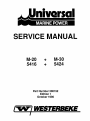
SERVICE MANUAL
M-20
5416
+
+
M-30
5424
Part Number 200152
Edition 1
October 1990
MODEL 20 & 30 INDEX
•
•
..
Specifications ..
Fuel System . . .
Lubrication System .
Oi- Filter . . . .
Combustion System
Valve Timing . . .
Compression Release
Cylinder Liner . .
Cylinder Head .
Piston and Rings
Crankshaft . . . .
Connecting Rod .
Gear Train . . ..
Camshaft Bearings
Main Bearings
Injection Pump
Water Pump ..
Flywheel ... . .
Starting Motor
Glow Plug . .
Wiring Diagram . .
Reference Charts . . . . . .
· 1-2
· 3-4
. . 5-6
• ••• 6
• • 7
. 8
· . 9
10
10
11
11
12
13
13
14
15
16
16
·
16-17
. . 17-18
• 19
20-24
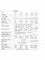
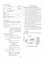
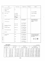
SPECIFICATIONS
MODEL
15
(5411)
20
(5416)
30
(5424)
40
(5432)
50
(5444)
--------------------.---------------------------------------------------------------------------11
16
44
24
32
-----------------------------------------------------------------------------------------------NO. OF CYLINDERS
2
2
3
4
4
---------------------------------------------------------------------------------.-------------BORE & STROKE
2.67 x 2.75
2.99 x 3.23
2.99 x 3.23
2.99 x 3.23 3.3 x 3.25
-----------------------------------------------------------------------------------------------DISPLACEMENT (CU. IN.)
31
45
68
115
91
-----------------------------------------------------------------------------------------------MAXIMUM R.P.M.
HORSEPOWER
3000
2800
2800
2800
•
3000
---------------------------------------------------------------------------------------~------
COMPRESSION RATIO
22:1
21:1
21:1
21:1
21:1
--------------------------------------------------------------------------------------~-----~---
TYPE
Vertical, water cooled, 4-cycle diesel engine
ELECTRICAL EQUIPMENT
12 Volt, 55 AMP Alternator, Electric Starter,
&Glow Plugs
Mech.
Fuel P\DIIP
Fuel Pump
Mech.
-----------------------------------------------------------------------------------------------Fuel Pump
-----------------------------~------------------------ ------------------------------.-----------
LUBRICATION (Engine)
2.2 Qts.
3.7 Qts.
5.6 Qts.
11.5 Qts.
Use SAE 30 HD (CD) or 10W40 heavy duty diesel
lubricating oil
8.~
Qts.
-----------------------------------------------------------------------------------------------LUBRICATION (Transmission)
(Std and V-Drive)
Fill to full mark on dipstick.
transmission fluid Type A.
Use automatic
-----------------------------------------------------------------------------------------------2:1
2:1
2:1
2:1
2:1
------------------------------------------------------------------------------------------------
TRANSMISSION REDUCTION
COOLING SYSTEM (7 PSI CAP)
Sea-water
cooled
Fresh
4.8Qts.
14 PSI
water
cooling
6 Qts.
14 PSI
system
8 Qts.
14 PSI
8 Qts.
14 PSI
--------------------~--------------------------------- -----_._-.---------------------------------
SEA WATER INLET 6 OUTLET
3/8" NPT
EXHAUST FLANGE
1-1/2" NPT 1-1/2" NPT
1-1/4" NPT
Diesel fuel number 2-D
FUEL
..
5/16" 1.0.
FUEL INLET HOSE
------------------------------------------------------ ------------------------------------~-~--
FILTERS, FUEL OIL
298854
298854
298854
2988~4
298854
----------------------------------------------.------------------------------------------------298852
299584
299927
299381
298852
----------------------------------------------------------------.---------------- ---------------
FILTERS, LUBRICATION OIL
Centrifugal type - all speeds
GOVERNOR
-----------------------------------------------------------------------------------.------------
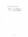
1
•
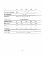
MODEL
15
(5411 )
20
(5416)
DGIN! OPlIATIJIIG TlJlPEIATUU
30
40
(S424)
(S432)
50
(5444)
1750 to 1900 r -----------------
MAX. OPERATING ANGLE
ENGINE ROTATION
Clockwise when viewed fro. V-belt end
PROPELLER ROTATION
Rilht Hand
(BOTH STD. AND V-DRIVE)
ENGI},,"! WEIGHT (Pounds)
245
365
425
490
545
LENGTH (Overall)
25.6"
28.0"
32.5"
36.2"
36.0"
HEIGHT (Overall)
21.2"
24.1"
24.6"
26.0"
26.0"
WID'11I (Overall)
20.7"
20.7"
20.7"
20.7"
21.4"
INJECTION NOZZLE
INJECTION TIMING
250 before top dead center - all .odel.
•
(2)
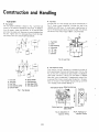
Construction and Handling
Fuel System
•
•
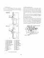
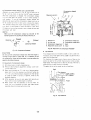
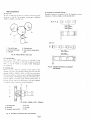
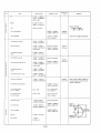
Fuel system
The fuel systf;)m schematic is shown in Fig. 1 with the fuel
flowing in the direction indicated by the arrows. To bleed air
from the system, loosen the vent plug "A" on the fuel filter
and crank the engine until there are no more air bubbles from
the vent. Tighten vent "A" and purge the air from the injection pump at vent "8" using the same procedures.
Fuel-filter
The fuel filter is of the cartridge type shown schematically in
Fig. 2. Under normal conditions it should only have to be
replaced every 400 hours. To install, apply a small amount of
fuel to the pack ing and tighten securely by hand. For removal,
the use of a filter wrench 15221-86611 is recommended.
(1)
/
(4J
(S)
1. Fuel filter
2. Caver
3. Pipe coupling
4. Vent plug
5. "0" ring
6. "0" ring
7. Element
\~
I)'
Fig. 2. Fuel Filter
1.
2.
3.
4.
5.
Fuel tank
Fuel cock
Fuel filter
Fuel injection pump
Injection pipe
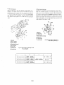
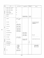
• Fuel injection timing
Fuel in)rction timing is adjusted by changing the number of
shims used between the pump and the gear case it fits into. See
Fig. 3. One shim corresponds to approximately 1.5 degrees in
crank angle. Therefore. injection will take place 1.5 degrees
later when a shim is added and 1.5 degrees earlier when a shim
is removed. The timing is correct when the pointer in the peerhole on the side of the flywheel housing lines up with the
"F1" marked on the flywheel. See Fig. 4.
6. Nozzle holder
7. Overflow pipe
A: Vent plug, filter
8: Vent plug, pump
Fuel injection pump Speed control lever
II~-
Fig. 1. Fuel System
Control rack pin
\
Injection timing
adjust shims
Fig. 3. Adjustment of
Injection Timing
(3)
Fig. 4. Inspection of
Injection Timing
.
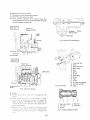
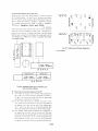
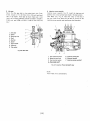
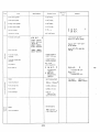
[Jel injection pump
The Injf'ction pump is the Bosch "Mine K type" It is a preci·
sian riPee nf eQlJipment machined to close tolerances and its
rerfor l1lance directly affects the performance of the engine.
Therefore, handle it with care.
(I)
co
ri0 .....
Ir~
1.
2.
3.
4.
5.
6.
7.
8.
9.
10.
11.
12.
13.
Injection pump ass'v
Deliverv valve holder
Deliverv valve spring
Deliverv valve gasket
Deliverv valve
Cvlinder pump element
Air bleeder screw
Packing
Hollow screw
Packing
Tappet guide pin
Clamp pin
Bolt
14.
15.
16.
17.
18.
19.
20.
21.
22.
23.
24.
25.
Adjusting plate
Control rack
Pump housing
Control sleeve
Upper spring sheet
Plunger spring
Lower spring sheet
Shim
Tappet ass'v
Roller
Roller bushing
Roller pin
Fig. 5. Fuel Injection Puf'(lP
(4 )
.. Handling the injection pump
Use care in handling and using the injection pump. As men·
tioned before, the injection pump is a precision piece of
equipment and care should be taken not to drop it or clamp it
trghtly when working on it. Also, be sure to use only clean
fuel that has been filtered. Oil drums left outdoors are always
considered to contain water, so always filter this fuel before
using.
Clean fuel is a must as the fuel is forced through parts of the
pump and nozzel with clearances of 0.0004 in. (1/1000mm)
which may easily be stuck or rusted by even the slightest
amount of water in the fuel.
.. Installing the injection pump
When installing the injection pump, make certain that the
control rack pin is correctly placed in the 0.2 in. (5mm) wide
groove of the fork lever (,) before tightening the attaching
bolts Refer to the diagram. If the bolts are drawn down with
the rack pin off the groove, the rack may over travel and stick
in this position. This would cause excess fuel flow, allowing
the engine to overspeed which would result in engine failure.
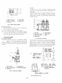
• Fuel injection'nozzle
The fuel injection nozzle, like the fuel injection pump, is also
a precision piece of equipment and should be treated with the
same amount of care.
• The nozzle cracking pressure
The nozzle cracking pressure is adjusted by adding or subtracting shi'ms from the top of the nozzle spring. Adding a
0.004 in. (0.1 mm) shim will increase the cracking pressure by
about 142 psi. (10 kg/cm2 ). The nozzle crack ing pressure is
1990 to 2133 psi. (140 to 150kgf/cm 1 )
• Spray pattern
The nozzle cracking pressure and fuel spray pattern are most
accurately checked by USing a nozzle "pop test" stand. If a
"pop test" stand is not available, remove the nozzles from the
engine, leaving the pressure lines connected.
ICAUTIOND
Hold the nozzles so that the high pressure spray from them
will 'not in any way impinge upon unprotected skin. The
atomized fuel will easily penetrate the skin and cause blood
poisoning.
Set the speed control lever at W. O. T. and operate the starter.
The needle valve, if it is working properly, will produce a high
pitched pulsating sound like that of a flute as fuel is sprayed
out. I f this sound is not heard or other problems are noted,
refer to the "Fuel Injection Pump & Nozzle Maintenance
Std." in 4.1 in "Engine".
oPrecaution D
1. Delivery nipple 1
2. Delivery nipple 2
3. Nut
(1) Assembly and disassembly of the nozzle should be done in
fresh clean fuel.
(2) The nozzle should always be installed as an assembly.
never by component parts.
(3) Remember never to let the nozzle spray contact unpro·
tected flesh.
(4) Tighten the retaining nut to 43.5 to 58 ft-Ib (6 to 8 kgf. ml
Any torque higher than this will cause slow action of the
needle valve and poor injection.
7. Nozzle spring
8_ Push rod
9. Pressure pin holder
4. Washer
5. Nozzle holder body
6. Adjusting washer
10. Nozzle nut
11. Nozzle piece
Fig. 6. Fuel Injection Nozzle
2.2 Lubrication System
Good
• Oil pump pick·up screen
The oil pump pick-up is located in the crankcase as shown in
Fig. 9 and is fitted with a metal screen. If the screen becomes
plugged, wash it off with diesel fuel or kerosene,
• lubrication system
The entire lubrication system is illustrated in Fig. 8, Oil from
the pump is forced through the replaciable paper element
filter. The. filter is equipped with a pressure regulated valve to
keep the pressure through the filter at 64-71 psi. (4.5-5
kgf/cm 2 ). From the filter part of the oil goes to the crankshaft
to lubricate the c;rankpins and the remainder goes to lubricate
the rocker arms.
An oil pressure switch is located in the passage from 'the filter
and controls the oil pressure. If the oil pressure falls below
14 psi. (1.0 kgf/cm2) the oil warning lamp" will light on the
dash panel." If the oil pressure lamp stays on after the engine
is running at normal speed, shut the engine off immediately.
Find and correct the cause of the low oil pressure before
operating again.
If the pressure regulating valve in the filter fails and the
pressure rises, a safety valve will limit the pressure to 140 psi.
Bad
vr.~A::;-CZ:)
(j)
1. Pressure spring
2. Pressure pin
3. Pressure pin holder
4. Nozzle body
5. Needle valve
6. Nozzle piece
Fig. 7. Nozzle
(10 kgf/cm2)
(5)
..
nProbable cause of low oil pressure n
(1) Clearance on one of the bearings is to great.
(2) One of the rocker arms is too loose.
(3) Faulty pressure regulating valve; pressure lower than
normal (replace the oil filter or clean the valve on the old
one with kerosene or diesel fuel.)
16 H.P .,
:,'
-T-·--·.~
~ffiY
l'===~~" -_
~
.I
Rocker arm
Rocker arm shaft
~-
.
-l.
Jr
t\
\
011 pump
Oil pan
pIck-up screen
ttJ.--Drain plug
Fig. 9. Detail of Oil Pump Pick-up
' ..,....
-.~
Relief
valve
24 H.P.
Rocker arm
Rocker arm shaft
I
'.". ___2__
,
Relief valve
...--7
7.
2.
3.
4.
5.
6.
7.
8.
9.
70.
Fig. 70. Oil Filter
Oil pump pick·up
screen
.
Fig. 8. Lubrication System
77.
72.
73.
74.
Filter cover assy
Cover
Safety valve assy
Safety valve
Plug
Spring
O-ring
Relief valve
O-ring
Plug
O-ring
Oil filter cartridge assy
Oil filter cartridge
Label
• Oil filter
(1) Rf'plilC~ the nil filter <It 0vmy nthpr oil change (f!very 150
hours)
(2) Undpr normal camiltiol1, it is only necessarv to changE'!
the nil filter at the specifipri intervills. If, however, thE'!
engine is used in EXTREME LY dirty conditions, the
prpSSIJrp. requlat 1r11 valV!' and silfptv villve should also be
rf'!lnoved ilIHi cleanp.d
(3) Whp.Jlf'v!)r thl' oil filter is rpplacmJ, rtm the enqine under
flO
IOild fnr il few fllinlltr~s lmtil the filter has been filled
ilnri then add oil to milk ... up tor what is contained in the
fdtp-r.
(6)
1. Relief valve compo
2. "0" ring
3. Spring
4. Ball valve
5. Valve sheet
Fig. 17. Pressure Regulating Valve
- .--Lj~\
:~~.
I
.1
n1J
•
Combustion air. of course. is brought in through the intake
valve when the descending piston creates a partial vacuum in
the cylinder.
Valve stem seals should be replaced whenever they are removed. If the stem seal are replaced. coat the stem liberally
with oil before inserting in the valve guide to prevent burning
the valve stem seal.
r
---~'~_ J
j
, __./_ L ___
1
-,
~
1, Safety valve body
2. SafetY valve spring
3. "0" ring
Valve
4. Oil filter base
5. Safety valve
(])-----_._---
Fig. 12. Safety Valve, Complete
~--
• Replacing engine oil
(1) Drain and replace the engine oil after the first 35 hrs of
orrriltion and every 75 hrs themafter.
(2) The t,il is easier to change il the engine is warm.
(3) Do not mix different brands 01 oil. If a different brand of
oil must be used. drain the oil and replace with all one
bl and. Also. do not mi x oils of different viscosities.
(1)-__ _
1.
2.
3.
4.
Valve cap
5. Valve stem seal
Valve spring retainer 6. Valve guide
Valve spring collet
7. Valve
Valve spring
Combustion System
• Combustion chamber
The engine utilizes a swirl type pm-combustion chamber
See (Fiq. 13). Fuel and air are mixed in this
chamber resulting in more efficient combustion. A glow-plug
is employed to preheat the fuel for easy starts down to 5° F
(-15°C).
Fig. 14. Structure of Valves
The dimensions of the replacement valves and valve guides are
shown in Fig 15. When new villve guides are installed. the
bores should be reamed to 0.316 to 0.315 in. (S.030 to
S.015mm) after installation. The valve head must be recessed
0.043 to 0.055 in. (11 to l.4mm) from thefaceofthecylinder head to prevent it from hitting the top of the piston.
ff
~
0.316-0.317in.
~"181J2=:"B:Osmmr ---'--.
0.313-0.314in.
7.960- 7.975mm)
A:
Uf nr
iU
I
Finished ID of guide
.installed in cylinder.
;;~=gdll$jr1,-_~tl_. . - j
(B.015-B.030mm)
T
c
r
(.5)
1. Nozzle holder
2. Nozzle piece packing
3. Glowplug
AI
.~
-"'"
-
-,
I
1.059 - 1.067in. 1.295 -1.303in.
(26.9"::V.Tmiii) 132.9 ':::"33.1mmJ
Fig. 15. Standard Dimensions
of Valves, Valve Guides,
Valve Gap
4. Cylinder head
5. Combustion chamber
Fig. 13. Combustion Chamber
0.043-0.055in. (1.1-1.4mm)
Fig. 16, Sinking of Valve
(7)
•
Valve timing
I
Adjust bolt (2)
When the valve clearance has hcp.n arl/usted as shown in
Fig. 17. the standard valve timinq shown in the chart can be
attained:
L
k
oc
nut (1)
I
,Valve clearance
I
~0.007-0.009 in.
.,
._t (0.18-0.22
~~
.
/
mm)
~ I(~ .~~
~.~
(r - - - _~~ I~
Ul'~
~------------
~
~
~
~~
-.;.
::..
i:i:
Fig. 17. Adjustment of Valve Clearance
Intake valve opens
I ntake valve closes
Exhaust valve opens
20° B TDC
-
.-
45° A BDC
--t-----.----50° B BDC
._----_.
-------- _._-
Exhaust valve closes
15° A TDC
Valve clearance 0.007 to 0.009 in. (0.18 to 0.22.mm) with
engine cold.
•
Rocker Arms
0.551 - 0.552i""·"'n.-;;:----:-_
I --- ---(14.000
14.027mm)
16 H. P. ,
j~
~W\MI
0.551 - 0.553;11.
-·-.,14.002-~T4~043mm)
I~tj
II
1_- . __ . ____
0.550 -0.551;n.
rij§i3:':'1 j~9iJ4miriJ
[ +-- ~
I
[ 24 H.P.]
I
.- .
0.551- 0.552in.
7T4.(jtJ{F~i4:02j~mT
(14.002 -. 14.043mm)
0.550 - 0.551in.
(iig 73 -::'-3.984iilfn)
I
- - - ---i---.-----.JU~I
Fig. 18. Standard Relative Position of Rocker Arms
(8)
-
·--l
• Compression release (Release wire is optional parts)
Assemblp thp parts as shown in Fig. 19. Pull the lever out as
Compression released
position
far as it will go. check to see that the 60° angle is attained
and that compression is released. The compression release
Operation position
~~
~
\
is to be used when the battery is low or when starting in
cold weather. Tn use the compression release. preheat the
glow pluq :ls IJsual. pull the compression release knob out as
II/cr;
®
".
\
/
C%l
.~
'
far as pOSSible and holrl it there while cranking the engine
This flartially' releases the enQine comflression enabling it to
turn faster in cold weather or when the battery is low. Once
the engi ne IS turninq fast enough to start. release the lever and
the engine will start.
(NOTE)
Make sure the compression release has returned to the
operating position by pushing the knob all the way in.
Released
1
1.
2.
3.
4.
elf;D
Operating released
Rocker arm
Oil filler cap
Compression re~ase lever
Adjustment access cover
5.
6.
7.
8.
Compression release nut
Compression release bolt
Shaft
Valve
Fig. 20. Adjustment of Compression Released
Fig. 19. Compression Released
•
~ CAUTION n
Do not pull the compression release lever when the engine is
running at high speed or under load. If it is necessary to use
the compression release while the engine is running reduce the
speed to idle before doing so.
•
Adjustment of compression release
Set exhaust valve in totally closed position
(2) Remove decompression adjustment window cover from
cy I i nrler head cover.
(3) Make valve clearance as "0" with use of decompression
(1)
adjust bolt From this position. turn the holt further by
1 to 1.5 turns. Decompression clearance will then be set
at 0.030 to 0.044 in. (075 to 1.125rnrn), which is the
designed clearance.
Top clearance
Top clearance should be 0.028 to 0.035 in. (0.7 to 0.9 mrn)
To adjust, usecyl inder gasket shims, 0.006 in. (0.15 mm) thick
each, onto the head side
For checking the measurr.rnent, place a piece of fuse on the
piston top and fix the cylinder head securely on the cylinder·
head flanqe The measurement is taken by the fuse. The liner is
level with the cylinder frarne at top surface.
The gasket shirns can be reused, so do not lose them.
Head
- Top clearance
--.-....,-- 0.028-0.035in.
(0.7-0.9mmJ
(4) After adjusting, be sure to lock adjust bolt securely so
that it will not unturn while engine is in service.
(5) Make certain that the cleanrance is not too wide. To
check this. turn crankshaft hy hand and make certain
valve disk does not contact With pistion top
Piston
Fig. 21. Top Clearance
(9)
• Boring and replacing the cylinder liner
Referriml to Fig 22. tht~ insirif~ diametPf of the linm sholiid
be checked at points 1.2. and 3 ann in the directions (a) and
(b). The liner on which the wear has excE'eded the service limit
can hf! bored and honed to 0.020 in (O.50mm) oversile.
The finished dimensions are 3.012 to 3.D13 in. (76.500 to
Models 5416 and 5424.'
76519mrn).
An oversi zed
piston ann rings must then he usen with this liner. Once this
()VerSiled liner has excepned its wear limit. it should be reo
placed with a new one. To install a new liner. coat the outside
liberally with oil, 'push into the block with a press and finish to
the standard size. When this is done, a standard size piston
must again be used.
_.
'~"K.1fE
I
.~
I
E
c..
:I:
.!: ot
N~
_0>
'rM_
,
...
I
,'"
f
"'II-
00·
NO>
_r";1
lot
I
JI-
Fig. 23. Tightening of Cylinder Head Bolts
2
•
l
.
L-.
CD
..
c1
3.130 ·3.131in.
(79.505 79.535mml
-"';
!
..
[24 H.P<
16 &24 H.P.
© Standard size
©Over size
2.992 - 2.993in.
(76.000 -·76.019mml
3.012 3.013in.
(76.500" 76.519mml
16 & 24 H.P.
Fig. 22. Standard Dimensions of Cylinder Liner
and Liner Bore in Block
• Tightening cylinder head capscrews (Fig. 23)
(1 I Tit" liflhtr~nlilfl tmQue of thp. cylincJAr head caf)screws is
~'>4 to f)8 II Ills. !7.fl to 8.0 kq·m) Numbers 7,8 and 11,
13 (.) ill tllf~ dii:lqrarn ale studs. The nuts on these studs
shouln <llsn he liqhtenerl to this torqup..
(2) All the capSCII?WS must be tiCjhtened uniformly. To do
this, tiqhtpn all Ihe capscrews in the orclm indicated on
thp. diaqram \lIllil thiN are Just snug. Then tighten each
one 1 (ond turn at a timp. in this same sequence each
time until all have bem tightened to the rp.Quired torque.
(3) The cylinder head capscrews should be re-tightened if
the enqine has not been used for a long time. The valve
lagh should also be adjusted p.ach limp. the cylinder head
capscrews are retorqlled If the cylinder h(~ild gasket has
b0.(!n replaced, rUIl the f'nfline lor allfllJl 30 minutes and
re'lighten the cylinder llt:ad capsrrcws as decsribed above.
(10)
Air cleaner
Main Moving Parts
• Pistons and piston rings
The ['Istons and piston rings are shown in Fig. 26. If the
cyl inder Imers have been bored oversi7e. oversize pistons
anti rings must be used. The piston is made of high silicon
AI·Alloy and is cam ground. The top compression ring is a
chrOln£' plated keystone type. the second compression ring is
discontinuous and undercut and the oil control ring is of the
standilrd expansion type.
s:
• Crankshaft and connecting rod
(1) The crankshaft is a heat treated steel alloy forging. The
crank pins are induction hardened for additional wear
resistance. Crankshaft endplay is 0.006 to 0.012 in. (0.15
to 0.31 mm).
(2) The crankpin bearings are aluminum.
When installing the connecting rods:
a) Clean both surfaces thoroughly.
b) Apply engine oil to the threads of the connecting rod
capscrews before installing and tighten each to 27 to
30.4 ft·lbs. (3.7 to 4.2 kg-mi.
End gap of rings on poston in cylinder
I
Diameter of piston skirt thru t of piston pin bore
E: Diameter of piston skirt perpendicular to piston pin
I 0.10i'l..J.2.5mm)
r~
III
L~,
I
.----1
lJ2.0Bl - 0.OB2in.
(2JjliF- 2.070mm)
0.191- 0.19Bin.
(5.010::: 5.030m"'1
0.905 '- 0.906in.
(23.000 - 23.013mm)
0.012- O.OlB,'!.:..,
(El!
(0.30 i
0.10in. (2,49mm) :
-.'=CC.".
0.Oj6B_O._t::J!121n·_n
I
(1.950-1.962mm) i
!
i...
0,1,957- 0.1965in."J
181
I
f4.91B-4.990mm)
i
i
0,45Ff1m)
i --
t
rt.--
0.010-
~
I
O.018i~
J
L--<i.\.'
(1i.'25- 0.45mm)
Fig. 26. Standard Dimensions of Piston
and Piston Rings
~
Standard size
Over size
IA
2.992in.
(76mml
3.012in.
(76.5mml
r---I
r--E
-
-
---
2.987in.
75.859mml
3.005 - 3.006in.
(76.339- 76.359mml
16 H.P.
2.989 . 2.990in.
(75.915 75.935mml
3.008 - 3.009;n.
06.415 - 76.435mml
24 H.P.
2.986
(75839
Over Sl7e
Name of Part
0.02in. (O.5mrn)
Piston 05
Piston ring 05
f--
Cylinder liner
>---------
------
The bearing caps are matched to each connecting rod
and should not be interchanged. Also. since there are
variations in machining from side to side, each bearing
cap and connecting rod are marked and should be
assembled so that the marks line up.
(3) In the event that the crankpins become worn and are no
longer serviceable, undersized bearings may be used.
When installing the undersize bearings observe the fol·
lowing precautions
a) Machine the crankpin diameter and radii to within
a few thousandths of the correct dimensions and
finish grind to the exact dimensions.
b) After finish grinding the bearing diameter and the radii,
chamfer the diameter of the oil hole with an oilstone.
If this IS not done an oil film will not form and the
bearing will sieze.
c) The crankpin should always be super-finished to
0000016 in. (00004 mm) or less.
d) Select the bearing from the chart that necessitates the
removal of the least amount of metal from the crankpin. Do not deviate from the chart dimensions as the
bearing life will be reduced if they are machined.
e) To determine the running clearance, assemble the connecting rod, bearing cap and bearing as described in
section 2 and measure the diameter anywhere within
the 1200 angle indicated in Fig. 28 and subtract the
crankpin diameter from this figure.
f) . The piston pin bushings are of lead bronze.
The inside diameter of the bushing should be finished
to 0906 to 0.907 in. (23.025 to 23.040 mm).
Mark
05
05
OS
OS
16 H.P.
3012 to 3.013in. (76.500 to 76.519mm)
(12f.1R max. to 2pR max.) by honing
--_ ... _ - -
--
( 11)
24 H.P.
n13n-Ol46m
f3]- 31mml
Radius 004-0.06!". 0 - 1,5mm/
, 1307-·, I'!313m
(43.959 - 43 975mml
{, ~l
-1 J!
1_
o 130-0. 146m
(3.3-3.7mm)
2.044 2.045111
(5'.921 51940mmJ
"" "."Tj~
" u 1r-.
(52064'
1/9,B7-:X; 13mm}
52131mm)
Fig. 28. Crankpin for Undersize Bearing
o 74'?-·-O,15Jm
0 782 -~ O. 793m.
2.050 - ) 052m
(1887 - '9.1.1mmJ
"'W
lOT
~1
~.
.
r
'~q
1 ..;l'1'!.!!.::.2000mm)It
0.078,·0,079"1
'0236
I (26
non
OJ
I
'02"m
16,021",m)
!
! 09065 ·0 90lJIIl
'- (23 025 - 23040mml
,
H. p ·1
r=1J[]--r.
rl.ufu-·~ --1l
i -
17307
1.l313m
143959
43.975mml
·.;.f1U~-.11.f-llrr;.1-l
,-.:!(
~.
j _ .t
..
. L-!
L.~~_~ -L ____
__
i.'
t
l
'.
f
2.052m
52. ,31mm}
2.247--2.248,"
,
157 084-57." 'm",1 1
0 782~O.J93111
!
(1987-20. 13mm)
I.
':
I
(23001,·
23[1"mrn}
o NJ--O 153m
(18870-'19. f]Omml
'.851m
47.02mrn)
- j
0.0.58 -·O.059In
482 - 1 495mml
r,
J
c.A':
.L_____._._!
Diameter of piston pin bushing after installation
Fig. 29. Standard Dimensions of Connecting Rod
Bearing and Bushing
(51.921- 1j1 .Q40mm)
(52.064
16 078mm}
I
2.044·- 2045m
2.050
1.850.
(47.000
, 0267",
~,-'"
- -
l 24
0255
(26 048
0.143- 0.753m
---+--.------,------T"' .
(18.81-- ,g. 13mm)
'
LUIJ
m
rn
rn
0018 ·0..079;,1.
(1970. - 2000mmJ
Fig. 27. Standard Dimensions of Crankshaft and Bearings
Pi] rt I'Jo
Sill"
Bpar ing
1. 7228
020
I
0.20 mrn undersi7P
I
---:~:-1-________~-]--~o 40
mm o
Metal
Mark
Crankrin Diarn.
I
'0 , 72"-i~'~~--I
(43.759 to 43.775 rnrn)
,.
!
Od:"",- -t ~;;4~ '0·'7·';"~-I
(43559 to 435"15 rnlll)
----'------
(12)
Runninq Clpilrancp
in.
('nm)
020US
0.001379
to 0.003819in.
(0.035 to 0.097rnrn)
040US
---------'-------'------------
Main Components
•
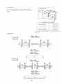
Gear train
Be sure to assemble thp. gears by matchinq the mating marks
as shown in Fig 30. The backlash of each gear is 0.002 to
0.005 in. (00415toO.1154mm)
• Camshaft and camshaft bearings
Standard dimensions are shown in Fig. 32. Camshaft running
clearance is: 0.002 to 0.004 in. (0.05 to 0.091 mm)
16 H. P.
"
~
rll
:{ :H~ 1 II 1 t 1~l..r t~ l' Inq1
f
I {
--------I.571-I.5731ft.
(J9 9:U-19.95Omml
1.575-1.576...
(.0.OOO--40.025mml
'1
I
]d''''t''.+ru'j
~~r ~-,-, ~L:. :=~
.•.-,.....
•••
.
If
~.~
24 H.P.
,. Crankshaft gear
2. Oil pump drive gear
3. Idle gear
4. Camshaft gear
5. Fuel injection pump drive
gear
..--.---- ........- -- . --r-----.
'
1.572-1.573..
(J9.9:U-J9.95Omml
1.575 -I.516ln.
(.OOOO-40.025mml
Fig. 30. Mating Marks of Gear Train
•
( ---{_~lJJJ l~trrnEro=oo
Crankshaft gear
Heat to about 176°F (BO°C) and slide on crankshaft If the
shaft and hore dimensions iJ[P such that the qear will not slide
easily. it may be heatp.d to a slightly higher temperature
for installation.
• Camshah gear
Rp.fer to Fig. 31. Place the camshaft retainer plate on the
camsh;Jft first. Shim the camshaft retainer rlatr~ out from the
camshaft 0.003 to 0.009 in. (0.07 to 0.22 mm) with shims
that can be pulled' nut after the gear is installed. Heat the gear
to aprroximately 176°F (BO°C) and sl'ide on the shaft until it
hlJtts up aqainst the retainer plate. Remove sracer shims. If
thp qe;'H will not slide on the shaft easily it tno may be heated
to a slightlY highp.r ternperature as descrrbed above.
~
Fig. 32. Standard Dimensions of Camshaft
and Bearings
.-
0.003 -. 0.009in. (0.07 - 0.22mm)
1. Camshaft gear
2. Camshaft
3. Camshaft retainer plate
4. Cir·clip
5. Pin plug
6. Key
Fig. 31. Assembly of Camshaft Gear with Camshaft
(13)
• Main bearing ass'y
Insert the bearings in the main bearinq hnusing halves as indicated in Figs. 33 & 34, using the thrust wilshers only on the
Journal nearest the flywheel. Coat the crankshaft Journals and
the bearing surfaces with engine oil, place the hOllsing halves
with bearings on the crankshaft, coat the capscrew threads
with engine oil and tighten to 21 to 25 ft-Ibs (3 to 3.5 kg-m)
-M8
• Main bearing housing
Installation of crankshaft with main bearings in engine block.
Slide the crankshaft assembly into the engine block, being
careful not to nick or scrape the crankpins. After the assembly
is in position make sure the oil passages are correctly lined up
Install the main bearing housing to engine block locking
capscrew and washer from the side to position the housing and
then install capscew (2) from the bottom and torque to 47
to 50 ft-Ibs (6.5 to 7 kg-m) - M 1
a
1.
2.
3.
4.
5.
6.
1.
2.
3.
4.
5.
6.
Bearing
Thrust washer
Thrust washer
Crankshaft journal
Main bearing
Cap screw
Fig. 33. Main Bearing Housing 3 with
7. Locking tab
Thrust Washe~
8. Locking tab
------.,_.-.-
.-
- ----------_.
0
Bearing
Cap screw
Locking tab
Main bearing housing
Cap screw
Locking tab
7. Locking tab
Fig. 34. Main Bearing Housing 7
Main Bearing Housing 2
d
1----_.._._---_ .. _-------- -- 1---._--_._---
-
5.156
5.157in.
Main bearing housing 1
1130.968 -130.986mm)
--_._-- _. __ ._---,--.------ ------ -."- .__ .. _.. _---5.1956 - 5. 1963in.
Main bearing housing 2
1131.968 - 131.986mm)
5.3137 - 5.3144in.
Main bearing housing 3 1134.968 --134.986mml
..
(14 )
--~.
------~-
.. -
--------_.
16 & 24 H.P.
1-- ------
2.2047- 2.2055in.
156.000 - 56.019mm)
24 H.P.
16 & 24 H.P.
•
Idler gear
Secure the idler gear shaft to the engine block with 3 capscrews. torque to 17 to 20 ft-lbs (2.4 to 2.8 kg-m) and bend
tabs of tab washer. Install gear as shown make sure it runs
freely. has a running clearance of 0.001 to 0.002 in. (0.020 to
0.054 mm) and 0.008 to 0.020 in. (0.20 to 0.51 mm) end
play.',
• Injection pump camshaft
Injection pump camshaft. Fig. 37. Install the bearings and
governor unit on the camshaft and install in the engine block.
Hour Meter Unit. Fig. 37. Insert the "tang" on the end of
the hour meter drive shaft into the slot on the end of the
injection pump camshaft and install as per the illustration.
1. Idler gear
2. Spacer
3. Retaining ring
4. Shaft
5. Bushing
6.. Spacer
7. Engine'block
8. Capscrew
9. Tab washer
/"
!4'/
,
/.
(5.'/
'.6
(71
Fig. 36. Idler Gear
1.
2.
3.
4.
Fuel injection pump
Speed control lever
Fuel control system
Hour meter unit·
5. Injection pump gear
6. Governor system
7. Injection pump camshaft
Fig. 37. Injection Pump Camshaft Assy
NOTE
*Hour meter unit is optional parts .
. (15)
• Attaching flywheel to crankshaft
Clean the entire contact suriil('P carPiully Coat the contact
surface with enginp. oil, wa~h all the oil oil with gasoline and
dry it throughly. Put the flywheel on and torque the CHpscrews
to 70 to 77 ft·lbs (10 to 11 kg·ml. Bend the locking tabs back
(1) Rust inhibitor and antifreeze should be used in accord·
ance with the recommendations in the related manuals
(2) Be sure to remove all debris that may be plugging the fins.
(3) Check the rubber shock mount nuts periodically to be
sure they are tight.
on the washers .
• Tensioning of fan belt,
The fan belt temion IS adJusted by moving the alternator
bracket in or' Ollt. The belt is properly tensioned when the
bel t deflection midway between the alternator pulley and the
crankshaft pulley is 0.25 to 0.35in (7 to 9mm) with a force
of 20 Ibs applied.' Proper belt tension is essential for good
engine cooling and belt life. See Fig. 38.
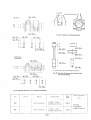
Fan pulley
• Cooling water pump
To install the enolinC] fan pulley on the pump, securely tighten
the nut (4) tn 50.6 to 57.9 ft·lbs. (7 to 8 kgf .m) torque.
16 & 24 H.P.
Tension pulley (Alternator pulley)
1. Pulley
2. Bearing
3. Key
4. Nut
5.
6.
7.
8.
9.
0.25 to 0.35in. (7 to 9mm)
Body
Shaft
Rotator
Case
Seal
Fan drive pulley
Fig. 38. Fan Belt Tensioning
Fig. 39. Water Pump
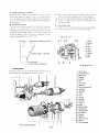
Starting Motor
The starting motor is of the standard bendix type drive with
actuating solenoid. The assembly is shown in Fig. 43.
1.
2.
3.
4.
5.
6.
7.
8.
9.
Starter ass'y
Drive end frame
Welch plug
Bushing
Set bolt·
Bolt
Drive lever
Solenoid
Over running clutch
10. Armature
11. Snap ring
12. Collar
2
r-.l
13.
14.
15.
16.
17.
18.
19.
20.
I
I
16
20
17
_ _ --'L
Fig. 43. Starter Assembly
18
I
- r-..J
13
19
(16)
21
22.
23.
24.
25.
26.
27.
Yoke
Set bolt
Packing
Field coil
Brush
Brush
Brush holder
Brush spring
Through bolt
End frame
Bushing
Packing
Return spring
Washer
End frame cap
•
Starter specifications
------,-
16 H.P.
------
24 H.P.
•
298783
Code No.
298876
f-.
Nominal
voltage
12V
Nominal
output
0.8 kW
Direction of
rotation
•
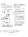
(1)
Precautions in care and handling of starter motor
The starting motor must be installed properly for the
starter pinion to mesh with the engine ring gear as it
should. If the ring gear and pinion do not mesh properly,
the pinion and starter housing may be damaged and in
extreme cases, the starter may not even turn.
(2) If the starter switch is turned on and the engine turns,
Solenoid ilctuilted with
overruning clutch
Type
* Insufficient brush contact
• Dirty or worn commutator
-----
--
but will not start, the cause is probably in the fuel system.
Check the fuel I ines and correct as necessary
1.0 kW
(3)
Clockwise, viewed from
pinion end
---
than 30 deconds the solder may melt from the armature
or the coil or lead wires may melt. Also, the battery will
Trouble shooting
be <iischarged tn such a <iegree and won't have suffirient
power fm another attempt at starting. A good rtlle 10
follow is to crank. for 10 seconds and pause for 10 seconds. Repeat until the engine starts
If the battery turns extremely slow or not at all, the cause may
lie in the battery, wiring or the starter
The Ilqhts are.
a very convenient tool for tracing the cause of thetr-ouble.
Ll<lht nlPlhocJ
The lise of thiS method, of course, assumes that the
are fllnctioning normally
(4)
If the starting motor is too far forward, the pinion will
not mesh properly with the ring gear and cause rapid
piston wear. Ad jus t for proper mesh.
(5)
Do not turn the starter switch while the enqine is running.
lights
(1) Liljh15 ar, ,11-'
Probable rallse
In attempting to start an engine, never use the startinq
motor for more than 30 seconds at a time without a pause
to let is cool down. The starting motor heats up very
rapidly when used and if it is used continously for more
Low hilttery, faulty contact at one of
the connections, faulty wiring. If the
If this is done, the pinion gear will contact the Tlng
qear, which is tlHning with the full force of the enqlOe
bilttery remains discharged hecause of a
malefaction in the charging syw~m, it
should be correr:ted before charging the
which may cause a broken pinion, bent shaf.t, broken
houslOg, etc.
battery
to prevent the rroblem
from reoccuring
(2) With battery fully charged
Glow Plugs
The glow plugs are the sheath type with the wiring diagram as
shown in Fig_ 44.
a) Symptom Lights do not light
Probable cause Battery terminal not properly
connected
b) Symptom' Lights hP.l.nmeextp.mely dim when crankinq the enqine and starter slows down or
stops
Probable cause
• Bad engine (rotatIOnal resistance too
great)
• Starter does not turn satisfactorily.
/
1. Glow plug
2. Glow plug
controller
3. Starter switch
4. Main switch
5, Regulator
6, Alternator
7. Battery
8. Starter
ArrT)ature shaft bent
Worn bushing
Pole core screw loose
* Field coil grounded or insulator short
Fig. 44. Circuit Diagram for Glow Plugs
circuited
* Armature coil grounded or insulator
short-circuited
c) Symptom
Lights are brirjht but starter does not turn
or turns very slowly.
Probable causes
• Starter terminal not r.onnected rroperly
* Solenoid switch not making contact
* Solenoid not workinq (coil grounded or
insulator short circuited)
* Faulty starter SWitch contact
(17)
•
Glow plug specifications
._J
16 H.P.
24 H.P.
298795
Code No.
.r
Number
I 3
::>
j
Vol tilfJP &
rw refl t
ArprOXIPlately 6.5 amp
(l')
10.5 V
'----
•
Glow plug controller specifications
Code No.
Current
•
(1)
16 H.P.
24 H.P.
299839
299839
13A
.
--
20A
Precautions in handling the glow plug
USf' the glow plugs only with
Universal
glow plug controller. If any other type is used, the heating
time will not match that of the glow plugs and cause
hard starting and various other problems
(2) As the glow plugs are ill rarallel, thl) controller heating
element will tllrn red even if. one of the rlugs is bad.
However, the time it takr~s for the controller heating
etement to get hot is less, which will cause the element to
bllrn out.
(3)
Rerlilcinq a faulty glow plug may not solve all the system
prohlems. Should thf' failed rlug indicate problems in
other areas beside the pili'], they should be checked out
iilv). The fl10st probablf' a[(~as are: improper fuel inJcction
tilTllflq, bad nOllie, wrong fuel, incorrect circuit connection, gas If'ak, etc.
(18)
I
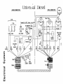
Univel~al
ENGINE CONNECTIONS
_0
2 CYl.
.-.
--,--
-t-
.. --..
,tr
,
GLOW I PLUGS
.
PANEL CONNECTIONS
I
__
3 _Cl,,-L _~
1-----"""----;
Diesel
Connect to ACC. term. on switch
i
•
FUEL PUMP
0'1
.......
E
Q)
......,
en
-L
Blue ~
>(J)
-co
(.)
.I-
......,
(.)
-w
Q)
I
I
•
FEHALE~!!
-----L.
-;-
OIL
TEMP
SENDER SENDER
FEMALE-l CDI~'j141
Z zz Z Z Z Z Z Z Z Z Z ZZ Z ZZ ZZ zz
:]1,1:]
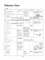
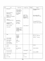
Reference Chart
Engine
Parts
.--
----iII>
Cylinder head tightness
Cylinder head surface distort inn
!:
Intake/e)(haust valve seat thickness
Standard 10
~
When installing. apply a generous
coat of engine oil onto the entire
surface of each bolt.
Y4S'
.--.
2.9980 in.
(76:15mm)
15416 & 5424
2.9921 -. 2.9929 in.
(76.000- 76.019mm)
15416 & 5424
0.0026·0.0041 in. !0065-·0.1~mml E side
0.0056 - 0.0071 in. (Q.141 - O. 180mm) I side
I
{
0.0276"'" 0.0354 in.
(0.7 ..... 0.9 mm)
Top clearance
c:
Remarks
45° 0.059 in. (1.5mm)
>
U
Maximum
limit
54.2"'" 57.9 fUbs
(7.5 --8 kg·m)
0.002 in below
(0.05mm below)
Ml0 x 125
J:
~
"0
Standard Value
Specifications
Items
O.059in. (1.5mm)
050 oversize liner 10
3.011.!3_- 3"o.l..?~_In.
(76.500- 76.519mm)
.:i
~
"0
c:
>
Piston clearance
(At piston skert)
U
Height above block surface
Type
Standard 00
c:
15416 & 5424
Dry
± 0.00098 in. (± 0.025 mm)
2.9921 in. (76mm)
Oversize 0.020 in. (0.5 mm)
o 9U55 -
Piston·pin boss 10
a:'"
interference Clearance
0.0004 in. 0.0004 in.
(OOllmm) (0.011 mm)
Piston·pin clearance
._-----_.
0.0118 - 0.0178in.
0.0492 in
~.3~0.45mm) _ _
(1.25mm)
0.0098 - 0.0158in.
\ (0.25 - 0.45mm)
Ring gap
(toP. 2nd)
(oil ring)
'"c:
Top ring width
Keystone type
c:
0
:;;
2nd ring width
0.0768 -0.0772in.
(1.95 - 1.962mm)
Oil ring
01960 -0 1965in
(4.978 - 4.99 mm)
a:
0.9071 in.
(2304 mm)
09060 in.
(23000 -23013 mm)
B
a:
Ring groove clearance
0.0037 -00047 in.
(0.093 -0.120mml
.. - ._._---0.5 oversize top ring surface should
be 0.0079 in. (0.2 mm) below
piston side surface.
above 0.0079 in.
(O.2mmJ
J
00008 -0.0020 in.
(0.02 -0.052 mm)
._---
----c
a:
00
a:
Pin·to·bush clearance
c
0
:;;
0.9056 ";"0.9059in.
(23.002-23.011mm)
0.0006-00015 in.
(0.014 -0.038 mm)
0.0059 in.
(0.15mm)
Small end 10
"0
0
a:
Small end width
1 0236 in. (26 mm)
Large end 10
1.8504 - 1.8512 in.
(47.000-47.020mm)
(without bush)
.§'"
u
II>
c:
c
a
u
1,0236 - 1.0244 in.
(26000-26.021 mm)
(without bush)
Large end width
. ~ 7~oogg:!'i
~
~
+
0.0008 in.
(0.02 mm)
M8)( 1
26.76- 30.38
ftlbs, (3.7 - 4.2
kg·m)
(20)
t TIJ:l.
. .
J-
_.
0.002in,
(005 mm)
?
Con"",,'ino
rod
4in. (100mm)
l~·±O;OOO79in.
_O.OOO79m.
(±O.02mm)
1.0079"'" 1.0118 in,
(256"'" 25.7 mm)
Rod torsion
(see diagram)
Rod bolt torque
Pin
(±O.02mm)
When installing, apply a generous
coat of engine oil onto the entire
surface of each bolt.
Maximum
Remarks
Lomit
r---.r--.--.-----------------------~.----------.----_+--------------+_----~--------------1
ID
1.7327 - 1.7345 in.
(44.01 - 44.056mml
(with metal)
Items
Width
0.7429 -0.7531 in
(1887-19.13mml
00
1 85 in. (47 mml
OJ'"
:2
c
a
Standard Value
Specifications
Center thickness
0.0583 - 0.0589 in.
(1.482 - 1.495 mml
-'"
c
'"
U
1-- -.
Runnmg clearance
0.0014 - 0.0038 in.
(0.035 - 0.097 mml
Axial clearance
0.0157 -0.0236in.
(0.4 -0.6 mml
0.0079in
(0.2 mml
Crank arm· to· large end clearance
------.------.---.----+---.---------+---------..,-----+-------------1
Cr~nkshaft
jurnal dia
20441 - 2 0449 in
(51.921-51.94mml
Main be"rlng ID
20465 - 20483 in
(5198- 52.025mm)
(with metal)
Crankshaft metal (21
Width
07429 -07531 in.
(1887 -1913 mml
I
Running clearance
0.0016-0.0041 in.
(004 -0.104mml
0.0079 in.
(02 mml
.---------.----.-----+------------+------+----+-----'---------1
0>
C
Crankshaft jurnal d,a
20449 -2.0449 in.
(51921 -51.94mm)
Gear'Slde main bearing ID
20465 -2.0488 in
(5198 -52.039mm)
(with metal)
CrankShaft metal (1 I
Width
0.7823 - 0.7925 in.
(19.87- 20.13mm)
Crankshaft metal (11 OD
2.2485 - 2.2474 in.
(57.111 - 57.084mml
I
Running clearance
o 0016 -0.0046 in.
j (004 -0118 mml
0.0079 in.
(0.2 mml
----- -----.---f------------------1~-------_+----+------------_1
f--
Crank,pln jurnal dia
1.7307 -1.7313 in
(43.959 - 43975mml
0.0047in.
(0 12 mml
Crankshaft Side clearance
Cr~nk hearing cap
bolt (11 torque
Crank bearing car
holt (21 torque
When installing, apply a generous
coat of engine oil onto the entire
su rface of each bolt
0.0059 - 0.0122 in.
(015-0.31 mml
M 8 x 1.25
21 7 - 283 tUbs
(3 -3.5 kg.ml
M 10 x 1.25
47.0 -506ft Ibs.
(6.5 -7 kg.rn)
. - .-.--- .-.-.--.-.-----------1-..-.- - -.. --.-------+-----------+--..----+--------------1
Cam bearing I D
Cam shaft dia.
~
1 5748-15758 in
(40 000-40 025mm)
15722-1 5728 inl
(39.934-39 .950mm)
Running clearance
1
0.0020 - 0.0036 in.
1(0.05--0.091 mml
(/9.5
0.0028-00087 in.
(0.07 - 0.22 mm)
Ax ial clearance
.c.
VJ
0.7677 in.
m~)
I
E
u'"
Cam 11ft
0.2165
C~rn
1 3134 in
(3336 mm)
height
In
(5.5mm)
0.5457ik
(13.86 mm)
(21)
f\
I
1,3134 in.
(33.36 mm)
~ I
Parts
Items
Specifications
Number of teeth, crank gear
34
Number of teeth, Idel gear
79
Number of teeth, cam gear
68
Nllmber .of teeth,
Inwction pump gear
68
Standard V~lue
Maximum
limit
Remarks
Number of teeth, at! pump
drive gear
45
Backlash
r--
o 00163-{) 00454 in,
to 0415-{), 1154mm)
0,0118 in,
to,3mm)
-~~--------~~-~-----"---~---------t---------t-----t----------------1
ShlOkage
0,0433 '0,0551 in,
tl.l-- 14mm)
Face angle
Valve gUide bore s/:1ouJd be
reamed after inserted into
cylinder head,
I ntake bore
1,2953-1,3031 in
t32,9 - 33 1 mm)
Exhaust bore
1,0591-10669 in
(26,9 -27,1 mm)
Stem dia,
0,3134-{),3140, in
t7 ,960-7 ,975mm)
Valve.guide IQ
0,3156-{) 3161 in,
t8,015-B030mm)
Q)'
~:
>'"
--
Stem guide clearance
0,0016-{),0028 in
(004 ~0,07 mm)
V~ve
Q,0071-{) 0087 in
t018 -0.22 mm)
When cold,
26,46 Ibs./l ,3839in
(12kg/35, 15 mm)
Load and length when installed-
clearance
-
-
--
_.
Free length
OJ
~
1,6417-1,6614 in,
(41,7 -422 mm)
Spring pressure
Ci
Ul
,..
Q)
iii
Perpendicularity
3%
>
Spring pressure loss
when installed
----. -----~---------~-~-
Over,all length
Dia
15%
-------~------- r-,--~---- --~--t-----+---------------------
A 5984 in
(152 mm)
B 5,81895.8346 in
(14781482 mm)
0.2323-{),2402 in,
(59-6,1 mm)
(22)
-,
P"rts
1---
Item5
Maximum
Urn It
Standard Value
Specifications
Remarks
I-------------------.-+----------+--------{-----+-------------/
I ntake valve opened
I ntake valve closed
At 45° ABDC
Ex hill.jst valve opened
At 50° BBDC
Exhaust valve closed
At 15 ATDC
Iqn,t,on process
1-2
1-2-3
0'>
c:
E
t-QJ
2
o
>'"
[
[
16 H.P.
24 H.P.
Injectectinn tlmlnq
~-4------·-----------11-----------4-----------~r----_+----------------~
Trochoid tooth width
Use Engine Oil CD (oS)
U16 H. P.
Above 77°F (25°C). SAE30
0.5866 -- 0.5874in.
(14.90 . 14.92mm)
24 H.P.
Between 32 ° F - 77 ° F (0 ° C25°C).SAE20
0.8622'" 0.8630in.
(21.90- 21.92mm)
Outer rotor OD
Below 32°F (OoCI. SAElOW.
10W·30
1.9669- 1,9685in.
(49.96- 50.00mml
CI.
E
Trochoid·tn·body
o 0035-{} 0063 in.
CI.
clearance
(009 -0,16 mm)
:>
6
o 0039-{} 0059 in,
Troc!1oidto·body side
clearance
(010-0.15 mm)
64-71 psi.
(4.5 - 5 kgf/cml)
Oil pressure
[ 16 H.p.D
. Pump capar.ity
4.2 Gal/on/min.
(16£imin)
I 24 H. P.
At pump 2000 r.p.m.
5.8 Gallon/min.
(22£imin.l
a.
E
B
At pump 2116 r.p.m.
« 24 H.P.
. - - ·--·-------------------1----------11------ ----. -.
[16 H,P .
---+-----+-------------i
Model
Np·PFR3K55/2NP2
I nleC! ion pressure
1990 psi (140kg/cm 1)
Pump plunger dia
02165
in.(5.5mm)
.
.
Pump stroke
0.2756 in (7 mm)
Pump discharge
0.001300015 in 3 /rev
(23 ± 1 mm 3 'rev)
Cam speed
Rack position:
1400 r.p,m.
0.354 in (9 mm)
:>
Cl.
c:
o
u
'"
C
--- -------_ ... __.-------- _._----_._------+----------+------+--------------\
NDDN12SD12
Modf!1
1990 - 2133 pSi.
(14D-150kgf./cm 1 )
I njl'ct Ion pressure
(23)
-
Parts
Spec if ications
Items
.
Cooling system
Standard Value
---
Ma)(imum
Limit
Remarks
With pressurized radiator
(corrugated I
Natural circulation
16 & 24 H.P.
t-orceo circulation
Water pump (Z751-BW
and DHll0l-BI
E
~
Centrifugal pump
with thermostat
(impelled
Gear case to impeller
clearance
Circulation flow rate (Z751-BW
and DHll0l-B)
0.0232-0.437 in.
(0.59 - 1.11 mml
(Packing thickness)
26.4 Gallon/min
(100Q/min) or more
'">
Water temperature BOoC.
Total lift 19.34Ibs.!in 2 (lmAg)
C/)
;;;
iO
~
Impeller dia.
(Z751-BW and DHll01-BI
2.634"-2642 in.
(669-67.1mml
C>
SO
Pump speed 3450- 3550 rpm
0
0
w
Thermostat actuation
temperature
(Z751-BWand DHl101-B)
179.6"-203°F
(B2°C -95°CI
. "No pump for Z751-B and ZB51-B
Radiator cap pressure
12.B psi. (0.9kg/cm 2 ,
Fan belt length
HM 40.55in. (1030mml
.n perimeter
16 & 24 H.P.
HM 41.50in. (1054mml
in perimeter
---.
Model
16 H.P.
D
16 H.P.
}
NS70. dry
12V70AH
24 H.P.
24 H.P.
12VBOAH
>
2i
Electrolyte specific
gravity. discharge
1 120
Electrolyte specific
gravity. charge
1.2BO
(6BoF; 20°C)
Etectrolyte specific
gravity. overdischarge
1.30
Voltage
12V
Current
20A
Check interval
Every 1000 service
hours.
N70Z. dry
iii
CD
0
.,Ec
>
0
Brush spring pressure
Alternator
Insulation resistance
12.B pSi(0.9kg/cm 2 )
I nsulation resistance
0
iii
:;
C>
'"
II:
.,
01
!9
'0
± 15%
No failure at 500MV
Constant voltage
13.B .... 14.BV
Current
lOA
Cut-in voltage
12.5-13.5V
>
(24)
,"'-'"
Par"
I
I
1-.
Items
-'- ---------
Number of teeth. pinion
Number of teeth.
rIng gear
Specifications
Maximum
limit
Standard Value
Remarks
.
89
Insulation resistance
No failure at 500MV
~
"'
tn
Check interval
Every 1000
service hours
Insulation resistance
n 16 H.P.
Output
.~
Nominal value
0.8kW
n·1.0kW24H.P.
....
. _"--
..
- -.- --.---------
-_.
Hp.ad set bolt and nut
D
__ _------..
' - - -.
Apply a generous coat of
engme oil onto the entire
surfaces of all important
set bolts.
54.2-57.9ft Ibs.
(7.5 -8 kgf.m)
Ml0x 1.25
Flywheel set bolts
72.3 - 79.6 fUbs
(10 - 11 kgf.m)
QJ
=>
cr
M12 x 1.25
(;
I-
Crankshaft main bearing
set cap bolts
Ml0 x 1.25
0
47.0-50.6 fUbs.
(6.5 -7 kgf·m)
~
Crankshaft cap bolts
M8)( 125
21.7 - 25.3 fUbs.
(3.0 - 3.5 kgf·m)
Rocker bracket set studs
M8)( 1.25
17.4 -20.3 ftlbs
(24 -2.8 kgf.m)
Rod bolts
M8)( 1
26.8 - 304 fUbs.
(3.7 - 42 kgf·m)
M12
57.1 -665 ft.lbs.
(79 -9.2 kgfm)
MlO
35.4-41.2 ft.lbs.
(4.9 -5.7 kgf.m)
M8
17.4 -20.3 ft.lbs.
(2.4 -2.8 kgf·m)
M6
7.2 -8.3 fUbs.
(1.0-1.15 kgf·m)
co
C
0a.
-E
--
_."
Gp.neral set bolts
and studs
QJ
=>
cr
All these torques are applied to
those S45C bolts and studs
which have relief number "7" or
punch marks.
(;
I-
(5
CD
0 0 $-
Bolt Torques
fUbs (kgf-m)
............~~terial Grade
-........
Standard Bolt
i----.. -.---...- -.. -.-..
D;;;~"""""
1-------:·"::>--- - -.Nominal
SS41. S20C
M.8
Ml0
.-
289- 333
53.5
-------_._-_.._.;_.. -_46.3
......._--_ .•... _.
M14
.
79.6 -
92.6
123.0""'"' 141.0
M16
...... .•.... " ' M18
1808-2098
-_
M20
-.-.ur- .
p -
••••
_-_ __
_
35.4- 41.2
( 4.90- 5.701
.. _. --_...
'-"
_. -_._.... ..-- ... ....6.40- 7.40)
57.1(7.909.20)-.. ..
... _-_66.5
.. - ------_
..
(1100-1280)
91.1-1085
112.60-15.00)
.•. __ ._....
....
._--_.-_... _--- ---- (1700 -19.501
144.7 -166 4
(20.00 -23.00)
-_ _-_._
---_
9.0-
72- 8.3
(100 1 15)
..__ ._..
.. .- "'-'-17.4- 203
12.40- 280)
~---.---'
400- 460)
_-
_._-_._
21.7 -
10.5
25.3
(25 00 - 29.00)
__
(34:00 - 4000)
_-_ __ (2800 -
(25)
...
-
86.8
...75.9-- ..123.0-144.7
...•
191.7 -224.2
(17.00-2000)
._ ---------.
32.50)
253.2 - 296.5
(37.50 -4400)
361.6 -419.5
•.........
3.50)
( 6.20- 7.20)
._-- ------_._------
_---_.
202.5 - 23~ 1
.... - - ........
271.2 -318.2
1.25- 1.45)
3.00 -
44.8- 52.1
-.......-- ..- ... -- r--.- -.-.--
-.
245.9 -289 3
---------l
SCR3. SCM3lRefined)
.. -- - - - - - - . - - . - -.. ------- -----.------.------(
-
----------
Special Bolt
- - - - - . - . -..• - . - ..- - . - - - - . - - . - . - . - . - - - - - - -
S43C, S48C (Refined)
6.9
10 BO - 095)
.. ......... _•. - .- .. _._--(1.80- 210)
13.0- 15.2
5.8-
M6
M12
Special Bolt
. .... - -...- . - . -
-.- ..-.--.. -~--
(10.50-12.00)
(26.50 -31.00)
._..- - - -
- 41.00)
- - - - - - (35.00
----;
(5000 -58.001
Bolt material grades are shown by numbers punched on the bolt heads_
Prior to tlghtenong. be sure to check out the numbers as shown below:
Punched Number
----------- ---- - ---- -----------None
Bolt Material Grade
-
-- -- - --- --- --------- - - - - - - - - - - -
Standard Bolts
5541. 520C
Special Bolts
SCM 3. seR 3 (Refinedl
-----------------f--------- ----------- ----------- -------------7
Special Bolts
543C. S48C (Refined)
-------------- --+--- ---------------- --- ---------------------1
9
(26)
.