1
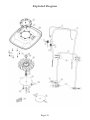
Owner’s Manual
Issue: 01.01.13
S/N: AF19-130000
©2013 Air Force Hover Mowers. All rights reserved.
Printed in the United States of America
Table of Contents
Contents
3
Specifications
4
Introduction
5
Warranty
6
Safety Symbols
7
Safety Precautions
8
Training
8
Preparation
8-9
Operation
9-10
Maintenance & Storage
10-11
Machine Assembly
Before Starting the Machine
13-14
13
Oil Type
13
Oil Level Check
14
Fuel Type
14
Operating the Machine
17
Cleaning the Air Cleaner
17
Servicing the Spark Plug
17
Keeping the Engine Clean
18
Deck Housing
18
Nuts and Bolts
18
Oil Maintenance
18
Cutting System Maintenance
19
Sharpening the SS Blades
19
Flexiblade Cutting System
Mower Storage
15
Cutting Flat Landscapes
15
Cutting Slopes and Banks
15
Stopping the Machine
16
Cutting Height Adjustment
16
20
20
Troubleshooting
21
Mower Parts List
22
Mower Exploded Diagram
23
Notes
Customer Information
15-16
Starting the Machine
17-20
Adjusting the Carburetor
Replacement
12
Prevent Engine Damage
Machine Maintenance
Page| 3
24-27
28
Specifications
Main Features:
(1) Handle Bar
(2) OPC Bail Arm
(3) Engine Brake Cable
(4) Pull Starter
(5) Engine Cover
(6) Footstop Assy.
(7) Deck
Model
F-19
Engine
Honda
Engine Type
GCV-160 OPC
Engine Speed
3300 rpm
Fuel Type
Unleaded
Fuel Capacity
0.24 gallons
Engine Oil Type
SAE 10W-30
Oil Sump Capacity
0.15 gallons
Cutting Width
19 inches
Dry Weight
39 pounds
Page| 4
Introduction
Thank you for purchasing the Air Force Hover Mower. The following pages
are to give you information about maintenance, operation, safety and
specifications instructions regarding your new mower. We strongly
recommend reading the manual before your first use.
Important: Familiarize yourself with all controls, operations and regular
maintenance points before your first use. If you require clarification, please
consult your local Authorized Dealer who can assist you further.
The Air Force Hover Mower is designed for cutting grass and low-to-theground vegetation. Any other use is considered contrary to the intended use
of the machine. Strict adherence and compliance with the conditions of
operation, repair and service as stated in this manual are required.
Precautions and safety tips found in this manual are standards that are
generally recognized and must be observed at all times. Any modifications to
this machine will relieve the manufacturer of liability for any resulting
damage or injury.
Air Force Hover Mowers should only be operated, repaired or serviced by
persons knowledgeable about the machines and familiar with their safety
features. Correct operation and maintenance will ensure a long service of the
machine.
All references to the left and right side of the machine are as viewed from
behind the mower in the operator’s position.
This manual is written based on information available at the time of
publications. Air Force reserves the right to amend the product,
specifications, and information within the manual without prior notification.
Page| 5
Warranty
LIMITED WARRANTY
The manufacturer warrants to the original purchaser that this unit shall be
free from defect in material and workmanship under normal use and service
for a period of one year from the date of purchase. The manufacturer of the
engine furnishes their own warranty and services through their authorized
network. The manufacturer is not included in said network.
To qualify for the full benefit of the Air Force warranty, the warranty
registration card must be returned to the distributor. If your selling dealer
does not offer this service, please fill out and return the enclosed warranty
registration card. Subject to the conditions and exclusions noted in the
Limited Warranty, we shall at our option, repair or replace any warranty part
during the applicable period. If you are in doubt or experience any difficulty,
please consult your Authorized Dealer for clarification.
A 90-day warranty period applies to those items which are subject to normal
wear and tear: blade systems, cables, etc.
This warranty does not apply to any unit that has been tampered with,
altered, misused, abused or used for hire, and will become invalid if
non-genuine parts are fitted at any time. This warranty does not cover minor
mechanical adjustments unless they are due to defective material or
workmanship. Consult the Owner’s Manual or your Authorized Dealer for
assistance when making these adjustments.
To make a warranty claim, contact your Authorized Dealer with your proof
of purchase, which states the machine serial number and date of purchase.
The dealer will, at our option, repair or replace any warranty part within the
duration of the warranty period. If your dealer does not provide services,
please contact the distributor directly with your proof of purchase.
This limited warranty gives you specific legal rights and is in addition to any
statutory rights to which you may be entitled; your statutory rights are not
affected by this warranty.
US / CANADA ONLY: Information regarding Authorized Dealers can be
obtained by contacting Seago International.
Web: www.seagousa.com
Phone: (800) 780-9889
Page| 6
Safety Symbols
Safety Alert: Be aware of potential hazards and danger
Manual: Read the instruction manual before using machine
Sharp Objects: Do not touch sharp objects while in motion
Moving Objects: Be aware of moving objects during use
Hot Objects/Surfaces: Hot surfaces and objects could cause
injury
Electrical Injury: Disconnect spark plug when working or
maintaining your machine.
Flammable Liquids: Use caution when using flammable liquids
Wear Protective Gear: Use protective gear at all times
Page| 7
Safety Precautions
Your machine is perfectly safe if used correctly. Failure to observe the
following precautions may result in serious injury.
Training
Read the Owner’s Manual and other informational material that came with
your new mower. If the operator or mechanic cannot read English, it is the
owner’s responsibility to explain this material to them.
Become familiar with the safe operation of the mower, operator controls, and
safety signs.
All operators and mechanics should be trained. The owner is responsible for
training all users.
The owner/operator is responsible for and can prevent accidents or injuries
occurring to themselves, others and property by adhering to the safety
instructions in this manual.
Never let children or untrained people operate or service the mower. Local
regulations may restrict the age of the operator.
Preparation
While using the machine, always wear substantial protective footwear and
long pants. Do not operate the equipment when barefoot or wearing open-toe
shoes.
Wear appropriate clothing including hard hat, safety glasses and hearing
protection. Long hair, loose clothing or jewelry may get tangled in moving
parts.
Evaluate the terrain to determine what accessories and attachments are
needed to properly and safely perform the job. Only use accessories and
attachments approved by Air Force.
Inspect the area where the equipment is to be used and remove all objects
such as rocks, toys, and wire which can be thrown by the machine.
Page| 8
Safety Precautions
Use extra care when handling gasoline and other flammable fuels. Vapors are
explosive.
(a) Use only approved fuel containers
(b) Never remove fuel cap or add fuel when the engine is operating
(c) DO NOT SMOKE while operating the machine
(d) Never refuel or drain the machine indoors
(e) Always use fresh fuel. Stale fuel can block the carburetor and
cause leaks.
Check that the Operator Presence Control (OPC) and safety switches are
attached and functioning properly.
Keep all parts in good working condition and all hardware tightened.
Replace all worn or damaged decals.
Do not use near children or pets.
A damaged cutting device and/or impeller must be replaced. Before use,
always visually inspect the cutting system to ensure that it is in good
condition. Do not operate with an out-of-balance cutting system or impeller.
Operation
Do not operate the engine in an enclosed space where exhaust fumes (carbon
monoxide) can collect. Refuel outdoors only and do not smoke while
refueling.
Do not operate the machine under the influence of alcohol or drugs.
Always pull the starter cord slowly until resistance is felt. Then pull the cord
rapidly to avoid kickback and prevent hand or arm injury. Ensure that feet
are away from the cutting system.
Operate only in daylight or good artificial light, keeping away from holes
and hidden hazards.
Avoid operating the machine in wet grass. Be sure of your footing while
using this product, especially when backing up. Reduced footing could cause
slipping.
Walk, never run when operating the Air Force Hover Mower.
Page| 9
Safety Precautions
Operate across the face of slopes, never up and down. Slow down and use
extra care when making turns or changing direction on slopes. Be sure to
travel in the recommended direction on slopes. Turf conditions can affect the
machine’s stability. Use caution while operating near drop-offs.
Never raise the deck with the blades in motion. Stop the engine before
moving the machine across areas other than grass.
Never operate without the safety guards in place.
Do not change the engine governor settings or over speed the engine.
Never touch the exhaust/exhaust guard or cooling fins with the engine is hot.
Stop engine and disconnect the park plug lead:
(1) Before clearing blockages
(2) Before cleaning, checking or working on the machine
(3) After striking a foreign object. Inspect the machine for damage
and ensure necessary repairs are made before re-starting
(4) If the machine starts to vibrate abnormally (check immediately).
An out of balance cutting device causes severe vibration.
Stop engine:
(1) Whenever you leave the machine
(2) Before refueling
Keep hands and feet away from the cutting system.
Maintenance & Storage
Disengage the drive, stop the engine and disconnect the spark plug. Wait for
all movement to stop before adjusting, cleaning or repairing. Keep hands and
feet away from moving parts.
Clean the cutting system, drive, muffler and engine of any grass or debris to
prevent fires. Clean up any fuel/oil spills.
Never store machine with gasoline in the tank within an enclosed area where
fumes may reach an open flame or spark.
Page| 10
Safety Precautions
Park the machine on level ground. Never allow untrained persons to service
the machine.
Remove the spark plug before attempting any repairs. Never check for a
spark when the spark plug is removed. Use an approved tester.
Keep all parts in good working condition and all hardware tightened.
Replace all worn or damaged decals. Always replace worn or faulty parts
with genuine Air Force Hover Mower parts.
Allow the engine to cool before storing in any enclosures. To reduce the risk
of fire hazard, keep the engine and the surrounding deck area free of grass,
leaves, and excessive grease.
Shut off fuel while storing or transporting. Do not store fuel near flames or
drain indoors.
If the fuel tank has to be drained, this should be done outdoors and when the
engine is cool.
Wear strong work gloves when removing and reassembling the cutting
device.
Never replace the cutting mechanisms with metal parts and only use cutting
mechanisms which are suitable for use at the operating speed of the machine.
Never start the engine with the air filter or the air filter cover removed.
Page| 11
Machine Assembly
Arrival Checklist
Remove the machine from its packaging and make sure you’ve received all
of the following parts to ensure your mower is correctly assembled:
(5) Throttle Securing Bolt
(6) Brake Securing Bolt
(8) Handle Securing Kit
(10) Footstop Securing Kit
(11) Deck/Handle Kit
(**) Cable Ties (not shown)
[If any pieces are missing, contact your dealer.]
Assembling the Machine
Step One: Lower Handlebar Assembly
To fit the lower handle to both sides, align the holes (footstop assembly on
the right side) and insert the sleeves, bushes, bolts, washers and nuts as
shown. (Uses Kit # 11 – Deck Handle Kit)
Step Two: Upper Handle Assembly
To fit the upper handle on both sides, align the holes and fit the bolts,
washers, and nuts. (Uses Kit #8 – Handle Securing Kit)
Step Three: Throttle & OPC Cable Assembly
Attach the throttle assembly to the outside right handle bar using the #5
Throttle Securing Bolt & washer. (Secure the cable to the upper and lower
handle using the provided ties.) Attach the OPC Cable in the front of the
right handle using the #6 Brake Securing Bolt through the back of the
handle.
Step Four: Footstop Assembly
To fit the footstop to the lower handle, align holes to the outside right lower
handle and fit the sleeve, bolt and nut. (Uses Kit #10 – Footstop Securing
Kit).
Page| 12
Before Starting the Machine
Prevent Engine Damage
To prevent damage to the engine, the machine is shipped without any fluids.
The engine must be filled with the correct grade of oil and fuel before
starting the engine.
Oil Type
When operating the Air Force Hover Mower, always use a high-quality
synthetic oil. Suggested classification is 10W-30. Additives are not
recommended. To prolong the life of your engine, change the oil after the
initial first five hours of use.
Oil Level Check
When checking the oil, keep the mower on a level surface. Remove the oil
cap, and wipe the dipstick with a clean cloth. Reinsert the dipstick without
screwing the cap back on, and remove it to check the oil level.
Correct oil level is when the brim of the liquid is at the FULL mark on the
dipstick. Do not overfill the engine with oil.
Fuel Type
Always use clean, unleaded fuel. Purchase fuel in a 30-day quantity to keep
fresh fuel on hand.
Fill to the base of the neck to allow for fuel expansion. Do not overfill the
fuel tank.
Page| 13
Operating the Machine
Ensure that the Operator Presence Control (OPC) Bail Arm moves freely and
returns to its resting position when released.
Starting the Machine
Step One:
Push the throttle control lever into the choke position. Turn the petcock to
the “on” position and open the tank vent (if fitted).
Step Two:
Release the handlebar from the footstop. Hold the OPC Bail Arm to the
upper handle, place your foot on the right side of the deck and slightly tilt the
machine toward you. This position ensures the fuel is beginning to circulate
and makes cranking the engine easy.
Pull the recoil starter rope lightly until you feel resistance, then pull briskly.
Return the starter grip gently.
Note: The OPC Bail Arm must be held firmly against the handlebar to start
and keep the engine running. If it is released, the engine and blade system
will stop.
Step Three:
Once started, move the throttle lever to the “run” position and allow the
engine to warm up.
To prevent damage, never pull the engine start grip while the engine is
running.
Cutting Flat Landscapes
Begin at the edge of the lawn and mow in a straight line back and forth as
you would with a regular walk behind machine.
Cutting Slopes and Banks
Begin at the top and swing the machine from side to side while carefully and
slowly moving down the slope. Keep the machine moving to reduce strain
on the engine.
Caution: Never stand below or beside the machine while mowing an
embankment. Always stand higher on the slope than the machine.
Page| 14
Operating the Machine
Stopping the Machine
Release the OPC Bail Arm to stop the machine. If the engine fails to stop,
pull the spark plug lead loose from the engine.
Cutting Height Adjustment
Your machine is shipped with the cutting disc in the highest position. Follow
these steps to adjust to the desired height of cut:
(1)
(2)
(3)
(4)
Turn the petcock to the “off” position.
Disconnect the spark plug.
Tilt the machine onto its left side, keeping the carburetor up.
Wearing protective hand gear, remove the Disc Securing Bolt
with holding the cutting system.
(5) Remove the three spacers and the cutting system.
(6) Reposition the spacers and cutting system for desired height of
cut.
(7) Fit the Disc Securing Bolt back to the machine.
Note: Large spacer must be positioned directly below the impeller at all
times.
Prevent An Accident
Inspect the cutting area before using the mower. Any objects other than grass
and leaves should be removed to prevent them from becoming projectiles.
Inspect for hidden obstructions, which would cause health and safety risks
when coming in contact with the cutting system. Make note of the
obstructions and mow around them.
Page| 15
Machine Maintenance
To prevent accidents, disconnect the spark plug whenever you are
performing any maintenance procedures on the machine.
Engine:
(1) Spark Plug / Lead
(2) Exhaust Guard
(3) Exhaust
(4) Oil Filter / Dipstick
(5) Starter Grip
(6) Fuel Cap
(7) Finger Guard
(8) Air Cleaner
(9) Carburetor
Adjusting the Carburetor
Adjustments should only be made by a Honda Certified Dealer. The engine
should not be adjusted to run at a speed in excess of standards set by Honda.
Doing so voids any warranty on the machine immediately.
Cleaning the Air Cleaner
Remove the air cleaner cover (1) by releasing the top catches (2) and tilting
away from the engine body until it’s released. Remove the air cleaner (3) and
tap it gently on a flat surface. If it’s too dirty or damaged, replace.
Do not brush or use fuel / oil to clean the air cleaner.
After cleaning the air cleaner, return it back to the case and insert the cover
on the bottom side, pushing the cover towards the engine body until the
catches hold in place.
Servicing the Spark Plug
Use only an approved spark plug tester. Replace the spark plug every 100
hours or every season (whichever occurs first). A spark plug wrench is
available from your Honda Certified Dealer.
Check the spark plug gap with a feeler gauge and set at 0.028 – 0.031”.
Page| 16
Machine Maintenance
Keeping the Engine Clean
Remove all debris and grass from the engine, including the exhaust and
exhaust guard, air ways in the top cowl, and surrounding deck areas on a
daily basis or after each use. Do not pressure-wash the machine during
cleaning. Water can contaminate the fuel. Always clean with a brush or
compressed air.
Grass and debris may clog the engine’s air cooling system especially after
prolonged operation or cutting tall, dry grass. The internal cooling fans and
surfaces may require cleaning to prevent the engine from overheating. We
recommend that this be carried out by a Honda Authorized Dealer.
Deck Housing
Remove debris and grass from both sides of the deck immediately after each
use.
Nuts and Bolts
Check all securing nuts and bolts regularly to ensure they remain tight.
Replace missing or damaged items immediately.
Oil Maintenance
Before each use, check the oil level and ensure that a correct oil level is
maintained. Refer to the “Before Starting the Machine” section for
instructions.
Change the oil after the initial first five hours of use. Follow the maintenance
schedule thereafter.
(1)
(2)
(3)
(4)
(5)
(6)
(7)
Run the engine until the fuel tank is empty.
Remove the spark plug lead.
Allow the engine to cool.
Drain the oil while the engine is warm (not hot).
Tip the machine over on to its left side (keeping the carburetor side up).
Drain the oil into a suitable container.
Refill with a high-grade 10W-30 synthetic oil.
Page| 17
Machine Maintenance
Maintaining the Cutting System
The condition of the cutting system and supporting mounting system should
be checked regularly for signs of wear or damage. A damaged cutting system
will become out of balance and cause the machine to vibrate excessively.
The cutting
system could damage the deck, impeller and other pieces under the deck and
lead to damage to engine or operator.
DO NOT use a damaged / unbalanced cutting system. Replace the cutting
system every two years or as wear and damage demand.
Regularly ensure the Disc Securing Bolt is tightened.
Prevent An Accident
Never work on the mower unless the spark plug lead has been removed.
ALWAYS wear strong gloves to protect your hands. ALWAYS use genuine
parts.
To replace the cutting system:
(1) Drain the fuel by running the engine dry (engine will stop).
(2) Remove the spark plug lead and allow the engine to cool.
(3) Turn the machine on its left-hand side (carburetor up).
If you only need to replace the blades or the blade securing kit, you would
not need to remove the cutting disc from the machine. If you need to replace
the entire cutting disc or the spacers, the disc will need to be removed y first
removing the Blade Retaining Bolt.
Sharpening the Stainless Steel Blades
Our stainless steel blades are reversible and can be sharpened. You simply
need to sharpen the sides when then they wear down. For best results, use
both sides until they need to be sharpened, and then sharpen both sides at the
same time.
Blades should be sharpened every 25 hours or as needed. Sharpen with a flat
file for best results.
Prevent An Accident
Remove the cutting blades from the cutting system before sharpening. Use
strong gloves while handling the blades.
Page| 18
Machine Maintenance
Flexiblade Cutting System Replacement
(1) Drain the fuel by running the engine dry (engine will stop).
(2) Remove the spark plug lead and allow the engine to cool.
(3) Turn the machine on its left-hand side (carburetor up).
(4) Replace the old line with 10 inches of new line.
Mower Storage
To prevent engine damage, engines must be drained of fuel when being
stored in excess of 30 days. Removing the fuel prevents gum from forming
in the fuel system and essential carburetor parts. By following our storage
procedure and referring to the engine manual as needed, your machine will
remain in good working order.
(1)
(2)
(3)
(4)
(5)
(6)
(7)
(8)
(9)
Drain the fuel by running the engine dry (engine will stop).
Disconnect the spark plug lead.
Change the engine oil.
Remove the engine spark plug, pour 0.5fl oz of engine oil into the
machine cylinder, and replace the spark plug. Avoid engine damage by
not exceeding the volume of oil. Do not replace the spark plug lead.
Slowly pull the recoil starter rope, turning the crankcase, to distribute
oil and prevent engine corrosion.
Clean all debris and grass from the engine cylinder, cooling fans, under
top cowl, and around and behind the exhaust / exhaust guard.
Lubricate the machine.
Treat metal parts with a water-repellant anti-corrosion product.
Cover the machine with a protective sheet and store it in a dry,
ventilated area.
Page| 19
Maintenance Schedule
Service Schedule
Maintenance
Before Each Use
(1) Check the fuel and oil levels
(2) Check blade system and tighten any loose bolts
(3) Check air filter – ensure it is dry
(4) Remove debris from the cutting system, impeller,
and air intake area of engine
After the First 5 Hours
(1) Change the engine oil (first machine oil change)
Every 5 Hours
(1) Tighten/replace any loose/damaged bolts, blades or
cutting disc
Every 25 Hours
(1) Check and clean the air filter area.
Every 50 Hours
Every 100 Hours
Every 150 Hours
Storage Over 30 Days
and Winterized Storage
(1) Change the engine oil
(2) Clean/replace air filter
(3) Sharpen/replace blades
(4) Clean/replace fuel filter
(5) Check for any leaks or deteriorations in the fuel
system and hoses
(1) Inspect the spark plug
(2) Clean/replace air cleaner
(3) Clean the cooling system (fins/starter area)
(1)Replace air filter
(2) Replace spark plug
(1) Empty fuel and oil
(2) Turn off fuel valve
(3) Disconnect the spark plug
(4) Add 15ml of fresh oil to the cylinder and pull starter
once to distribute oil
(5) Treat metal parts with water-repellant, anticorrosion product.
(6) Store in dry, ventilated area
This is a suggested maintenance schedule. Depending on terrain, the schedule
may need to be adjusted for dusty/rough conditions.
Page| 20
Troubleshooting
Problem
Causes
Corrective Action
Engine will not turn over
(1) OPC Bail Arm
released
(2) Incorrect oil level
(3) Obstruction under
deck
(1) Operate OPC Bail
Arm
(2) Check oil level
(3) Remove obstruction
Engine smokes
(1) Excess oil
(2) Air cleaner oil-soaked
or blocked
(1) Check oil level
(2) Service air cleaner
Engine runs then stops
(1) Fuel starvation
(2) Fuel cap vent blocked
(3) Petcock closed
(1) Fill fuel tank
(2) Clean fuel cap assy
(3) Open petcock
Engine will not start
(1) Engine under load
(2) Incorrect/
contaminated fuel
(3) Spark plug lead
disconnected
(4) OPC Bail Arm not
released
(5) Faulty spark plug
(1) Raise height of cut
(2) Drain tank and fill
with correct / clean fuel
(3) Connect spark plug
lead
(4) Operate OPC Bail
Arm
(5) Clean/adjust/replace
plug
(6) Check wiring
(6) Faulty wiring
Engine runs rough
Engine vibrate
excessively
(1) Spark plug lead
becoming disconnected
during use
(2) Faulty spark plug
(3) Air cleaner blocked
(4) Incorrect/
contaminated fuel
(1) Disc Securing Bolt
loose
(2) Blade Retaining Bolts
lose
(3) Cutting system out of
balance
(4) Bent crankshaft
Uneven cut
(1) Cutting system out of
balance
Poor hovering
(1) Engine running slow
(2) Impeller air vents
blocked
(3) Underdeck not clean
(4) Cutting system loose
Page| 21
(1) Connect spark plug
lead
(2) Clean/adjust/replace
plug
(3) Service air cleaner
(4) Drain tank and fill
with correct fuel
(1) Tighten/replace bolt
(2) Tighten/replace bolts
(3) Balance/replace
cutting system
(4) Contact your Honda
Certified Dealer
(1) Balance/replace
cutting system
(1) Contact your Honda
Certified Dealer
(2) Check and unblock
(3) Clean
(4) Tighten cutting system
or replace Disc Securing
Bolt.
Mower Parts List
Key
1
Part No.
AF1200
Description
Upper Handle
2
AF1201
OPC Bail Arm
1
3
AF1202
Throttle Cable
1
4
AF1203
Brake Cable
1
5
AF1204
Throttle Securing Bolt
1
6
AF1205
Brake Securing Bolt
1
7
AF1206
Lower Handle
1
8
AF1207
Handle Securing Kit
2
9
AF1208
Footstop
1
10
AF1209
Footstop Securing Kit
1
11
AF1210
Deck/Handle Kit (2 sets/kit)
1
12
AF1211
Engine Frame
1
13
AF1212
Engine Securing Kit
1
14
AF1213
Deck
1
15
AF1214
Deck/Frame Nut Kit
1
Set of 7
16
AF1215
Deck/Frame Bolt Kit
1
Set of 7
17
AF1216
Woodruff Key
1
18
AF1217
Hub Spacer
1
19
AF1218
Drive Hub
1
20
AF1219
Impeller
1
21
AF1220
Large Spacer
1
22
AF1221
Shaft Spacer Kit
1
23
AF1222
Blade System Disc
1
24
SE02214
SS Blade Kit
1
25
SE18370
Blade Securing Bolt
1
26
AF1225
Blade Retaining Spigot
1
27
AF1226
Washer
1
28
AF1227
Disc Securing Bolt
1
29
SE00603
QC Blade Kit
1
Set of 6
29
SE01206
QC Blade Kit
1
Set of 60
30
SE02214
Flexiblade
1
31
AF1223
String System Disc
1
Not Shown
*
AF1224
Cable Ties
2
Not Shown
*
*
GCV-160 OPC
AF1228
Engine
Air Force Decal
1
1
Not Shown
Not Shown
*
AF1229
Fuel Warning Decal
1
Not Shown
*
AF1230
Safety Decal
1
Not Shown
*
*
AF1231
AF1232
Caution Decal
QC Kit Complete
1
1
Not Shown
Not Shown
*
AF1233
SS Kit Complete
1
Not Shown
Page| 22
Qty.
1
Notes
2 sets / kit
Set of 3
Roll of 85’
Exploded Diagram
Page| 23
Notes
Page| 24
Notes
Page| 25
Notes
Page| 26
Machine Code:
Serial Number:
WARRANTY
REGISTRATION
THIS CARD MUST BE COMPLETED AND
RETURNED TO REGISTER YOUR MACHINE
Course/Business Name:
Address:
Phone:
Contact Person:
Purchase Date:
Price Paid:
Email:
Dealer Name:
Dealer Location:
Sales Representative:
DATA PROTECTION:
By submitting this form to Seago International, you are authorizing Seago to hold your information for future warranty and
future sales/marketing promotional. The information on this card will be held and used by Seago International, Inc. only.
No information on this card will be sold or distributed to a third-party for any reason.