1
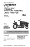
Operator's Manual
II
Ic..m..w!
LAWN TRACTOR
26.0 HR* 54" Mower
Electric Start
Automatic Transmission
Model No.
917.28858
• Espafiol, p. 37
_
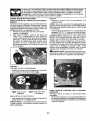
differently from previously built engines. Before you start the
This
product
has understand
a low emission
engine,
read and
this engine
manual.which operates
IMPORTANT:
For answers to your questions
Read and follow all Safety
about this product,
Rules and Instructions before
operating this equipment.
1-800-659-5917
Call:
Sears Craftsman Help Line
5 am - 5 pro, Mon - Sat
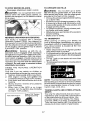
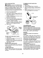
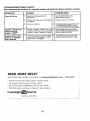
Gasoline containing up to 10% ethanol (EIO) is acceptable for use in this machine.
The use of any gasoline exceeding 10% ethanol (El0) will void the product warranty.
Esta m_quina puede utilizar gasolina con un contenido de hasta el 10% de etanol (EIO).
El uso de una gasolina que supere el 10% de etanol (EIO) anular_ la garantfa del producto,
Sears Brands Management
Corporation,
Hoffman
Visit our Craftsman website:www.sears.com!craftsman
581881296 Rev. 1
Estates,
IL 60179
U.S.A.
*As rated by the engine manufacturer
Warranty ..................................................
2
Safety Rules ............................................
3
Product Specifications .............................
6
Assembly/Pre-Operatfon
.........................
7
Operation ...............................................
13
Maintenance
Schedule ..........................
21
Maintenance ..........................................
21
Service and Adjustments ....................... 26
Sto rage ..................................................
31
Troubleshooting
.....................................
32
Sears Service .......................... Back Cover
Craftsman Riding Equipment Warranty
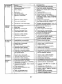
CRAFTSMAN FU LL WAR RANTY
FOR TWO YEARS from the date of purchase, all non-expendable
parts of this nding equipment are
warranted
against any defects in material or workmanship.
A defective nomexpendabte
part will
receive free in-home repair or replacement
ff repair is impossibEe.
FOR FIVE YEARS from the date of purchase, the frame
warranted against any defects in material or workmanship.
free in-home repair or replacement if repair _s impossible.
and front axle of th_s riding equipment are
A defective frame or front axle will receive
FOR 90 DAYS from the date of purchase, the battery (an expendable
part) of th_s riding equipment
is warranted against any defects in material or workmanship
{our testing proves that it will not hold a
charge). A defective battery will receive free in-home replacement.
ADDITIONAL
LIFETIME
LIMITED
WARRANTY
on CAST
IRON
FRONT
AXLE
(if equipped)
FOR AS LONG AS fT IS USED by the original owner after the fifth year from the date of purchase, the
cast iron front axle (if equipped) of th_s riding equipment _swarranted against any defects in material or
workmanship.
With proof of purchase, a defective cast front axle will receive free in-home replacement.
WAR RANTY
SERVICE
For warranty coverage details
web site. www.craffsman.com
to obtain free repair or replacement,
In all cases above, if part repair or repJacement is impossible,
free of charge with the same or an equivalent model.
call 1-800-659-5917
the riding equipment
All of the above warranty coverage
is void if this riding equipment
commercial
services or if rented to another person.
This warranty
include:
•
•
covers
ONLY defects
in material
and workmanship.
is ever
Warranty
or visit the
will be replaced
used while
coverage
providing
does NOT
Expendable
parts (except battery) that can wear out from normal use w=thin the warranty
includ=ng but not limited to blades, spark plugs, air cleaners, belts, and oil filters.
Standard maintenance
servicing, o_1changes, or tune-ups.
period,
• Tire replacement
or repair caused by punctures
from outside objects, such as nails, thorns,
stumps, or glass.
• Tire or wheel replacement
or repair resu[ting from normal wear, accident, or improper operation or
maintenance.
• Repa=rs necessary
because of operator abuse, including but not limited
towing objects beyond the capability
of the riding equipment,
impacting
frame, axle assembly or crankshaft,
or over-speeding
the engine.
to damage caused by
objects that bend the
•
Repairs necessary
because of operator
negligence,
including but not limited to, electrical and
mechanical
damage caused by improper storage, failure to use the proper grade and amount
of eng=ne o_J, failure to keep the deck cJear of flammable
debris, or failure to maintain the riding
equipment according to the instructions
contained in the operator's
manual
• Engine (fuel system) cleaning or repairs caused by fuel determined to be contaminated
or oxidized
(stale). In general, fuel should be used within 30 days of its purchase date.
• Normal deterioration
and wear of the exterior finishes, or product label replacement.
This warranty g_ves you specific regal rights, and you may also have other rights which vary from
state to state.
Sears Brands
Management
Corporation,
Hoffman
2
Estates,
IL 60179
_DANGER:
This cutting machine is capable of amputating hands and feet and
throwing objects. Failure to observe the following safety instructions could result
in serious
injury or death.
,_WARNING:
In order to prevent accidental starting when setting up, transporting,
adjusting or making repairs, always disconnect spark plug wire and place wire where
it cannot contact spark plug.
•
Before and while backing, IQok behind
and down for small children.
Never carry children,
even with the
blades shut off. They may fall off and
be seriously injured or interfere with safe
machine operation. Children who have
been g=ven rides in the past may suddenly
appear in the mowing area for another
ride and be run over or backed over by
the machine.
Never allow children to operate the machine.
_kWARNING:
Do not coast down a hill in
neutral, you may lose control of the tractor.
_.WARNING:
Tow only the attachments
that are recommended
by and comply with
specifications
of the manufacturer
of your
tractor. Use common sense when towing.
Operate only at the lowest possible speed
when on as[ope. Too heavy of a load, while
on a slope, is dangerous.
Tires can lose
traction with the ground and cause you to
lose control of your tractor.
_kWARNING:
Engine exhaust, some of
its constttuents, and certain vehicle components contain or emit chemicals known to
the State of California to cause cancer and
birth defects or other reproductive harm.
_,WARNING:
Battery posts, terminals and
related accessories contain lead and Lead
compounds, chemtcals known tothe State of
California to cause cancer and birth defects
or other reproductive harm. Wash hands
after handling.
•
_(_WARNING!
SERIOUSLY
THIS
follow
CHILDREN
INJURED
OR
CAN
KILLED
•
-
•
•
•
•
BE
BY
EQUIPMENT.
Carefully
read and
all of the safety instructions
below.
Tragic accidents can occur if the operator
is not alert to the presence of children.
Children are often attracted to the machine
and the mowing activity.
that children will remain
saw them.
Never assume
where you last
Use extreme caution when approaching
blind corners, shrubs, trees, or other
objects that may block your view of a
child.
II, GENERAL
I. CHILDREN
_kWARNING!
CHILDREN
CAN BE INJURED BY THIS EQUIPMENT. The American Academy of Pediatrics recommends
that children be a minimum of 12 year of
age before operating a pedestrtan controlled
lawn mower and a minimum of 16 years of
age before operating a riding lawn mower.
Keep children out of the mowing area
and in the watchful care of a responsible
adult other than the operator.
Be alert and turn machine off if a child
enters the area.
•
OPERATION
Read, understand, and fotlowallinstructions on the machine and in the manual
before starting.
Do not put hands or feet near rotattng
parts or under the machine. Keep clear
of the discharge opening at all times.
Only allow responsible adults, who are
familiar with the instructions, to operate
the machine.
C_ear the area of objects such as rocks,
toys, wire, etc., which could be picked
up and thrown by the blades.
Ensure the area is clear of bystanders
before operating. Stop machine ffanyone
enters the area.
Never carry passengers.
Do not mow in reverse unless absolutely
necessary. Always look down and behind
before and while backing.
Never direct discharged material toward
anyone.
Avoid discharging
material
against a wall or obstruction.
Material
may ricochet back toward the operator.
Stop the blades when crossing gravel
surfaces.
Do not operate machinewithoutthe
entire
grass catcher, discharge chute, or other
safety devices in place and working.
• Slowdown
before
turning.
• Watch for holes, ruts, bumps, rocks, or
Never
leavea running
machme
unat- other hidden objects, Uneven terrain
tended.Always
turnoffblades,
set
could overturn the machine. Tall grass
parking
brake,
stopengine,
andremove can hide obstacles,
keysbefore
dismounting.
• Choose a low ground speed so that you
• Disengage
blades
whennotmowing. will not have to stop or shift while on the
Shutoffengine
andwaitforallparts
to
slope.
come
toacomplete
stopbefore
cleaning" Do not mew on wet grass, Ttres may
themachine,
removing
thegrass
catcher, lose traction. Always keep the machine
orunclogging
thedischarge
chute.
in gear when going down slopes,
Operate
machine
onlyindaylight
orgood Do not shift to neutral and coast down hill.
artificial
light.
• Avoid starting, stopping, or turning on a
Donotoperate
themachine
while
under slope, ffthetires Iosetraction, disengage
theinfluence
ofalcohol
ordrugs.
the blades and proceed slowly straight
• Watch
fortraffic
whenoperating
nearor
down the slope.
crossing
roadways.
•
Keep all movement on the slopes slow
• Useextreme
caution
whenloading
or
and gradual.
Do not make sudden
unJeading
themachine
intoatrafleror
changes
in speed or direction, which
truck.
could cause the machine to roll over,
• Always
wear
eyeprotectton
when
operat- Use extreme caution while operating
ingmachme.
machine with grass catchers or other
• Useearprotectors
toavoiddamage
to
attachments; they can affect the stabilhearing.
ity of the machine. Do no use on steep
• Dataindicates
thatoperators,
age60
slopes.
years
andabove,
arerevolved
inalarge Do not try to stabilize the machme by
percentage
ofriding
mower-related
injuputting your foot on the ground.
ries.These
operators
should
evaluate* Do net mow near drep-offs, ditches,
thetrability
tooperate
theriding
mower or embankments. The machine could
safely
enough
toprotect
themselves
and
suddenly roll over if a wheel Is over the
others
fromserious
injury.
edge or if the edge caves in.
• Followthemanufacturer'srecommenda•
If machine stops while going uphill,
tionforwheel
weights
orcounterweights.disengage blades, shift into reverse and
Keepmachine
freeofgrass,
leaves
or
back down slowly.
other
debris
build-up
which
cantouch
hot
Do not turn on slopes unless necessary,
exhaust/engine
parts
andburn.
Donot
and then, turn slowly and gradually
allowthemower
deck
toplowleaves
or
downhill, if possible.
otherdebris
whichcancause
build-up
tooccur.
Clean
anyoilorfuelsptllage
before
operating
orstonng
themachine.
Allowmachine
tocoolbefore
storage,
!11.
SLOPEOPERATION
IV, TOWING
a machine that has a hitch
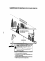
_WARNING!
When
loading
orunloading• Tow only with
for towing. Do not attach towed
thismachine,
donotexceed
themaximum designed
except at the hitch point.
recommended
operation
angleof 15°. • equipment
Followthemanufacturer'srecommendaSlopes
areamajor
factor
related
tolossof
tion for weight limits fortowed equipment
control
andtip-over
accidents,
which
can
and towing on slopes.
result
insevere
injuryordeath.Operation Never allow children or others in or on
onallslopesrequires
extreme
caution.
If
towed equipment.
On slopes, the weight ofthetowed equipyoucannot
backuptheslopeorifyoufeel
ment may cause loss of tractton and loss
uneasy
onit,donotmowit.
of control.
•
Mow up and down slopes,
not across.
•
4
Travel slowly and allow extra distance to
stop.
V. SERVICE
GENERAL
SAFE HANDLING
•
OF GASOLINE
To avoid personal injury or property damage, use extreme care in handling gasoline.
Gasoline is extremely flammable and the
vapors are explosive.
Extinguish all cigarettes, cigars, pipes,
and other sources of ignition.
• Use onfyapproved
gasoline container.
• Never remove gas cap or add fuel with
the engine running.
• Allow engine to cool before refueling.
Never fuel the machine indoors.
• Never storethe machine orfuel contatner
•
•
•
where there is an open flame, spark, or
pilot light such as on a water heater or
other appliances.
Never fill containers inside a vehicle or
on atruck or trailer bed with plastic liner.
Always place containers on the ground
away from your vehicle when filling.
Remove gas-powered
equipment from
the truck or trailer and refuel it on the
ground. If this is not possible, then refuel
s uch equipment with aportable container,
rather than from a gasoline dispenser
nozzle.
Keep the nozzle in contact with the rim
of the fuel tank or container opening at
aJltimes until fueling is complete. Do not
use a nozzle lock-open device.
{ffuel is spilled on clothing, change clothing immediately.
Neveroverfilffueltank.
Repiace gas cap
and tighten securely.
•
•
•
•
•
•
SERVICE
Never operate machine in a closed area.
Keep all nuts and bolts rig ht to ensure the
equipment is in safe working condition.
Nevertamperwithsafetydevices,
Never
interfere with the intended function of a
safety device or reduce the protection
provided by a safety device. Check there
proper operation regularly. NEVER operate a machine with a safety device that
does not function properly.
Keep machine free of grass, leaves, or
other debris build-up.
Clean oil or fuel
spillage and remove any fuel-soaked
debris.
Allow machine to cool before
storing,
If you strike a foreign object, stop and
inspectthe machine. Repair, if necessary,
before restarting.
Never make any adjustments or repairs
with the engine running.
Check grass catcher components and the
discharge chute frequently and replace
with man ufacturer's recommended parts,
when necessary.
Mower blades aresharp, Wrapthe blade
or wear gloves, and use extreme cautio n
when servicing them.
Check brake operation frequently. Adjust
and service as required.
Maintain or replace safety and instruction
labels, as necessary.
wUse ear protectors to avoid damage to bemiring.
Always wear eye protection when operating machine.
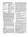
PRODUCT
SPECIFICATIONS
Gasoline Capacity
and Type:
3 Gallons (11,35 L)
Unleaded Regular
Oil Type
API: SG-SL):
SAE 30 (above 32°F/0°C)
SAE 5W30
(below 32°F/0°C)
Oil Capacity:
w/Filter:
wio Filter:
Spark Plug:
In the state of California the above is required
by law (Section 4442 of the California Public
Resources Code). Other states may have
similar laws. Federal laws apply on federal
lands. A spark arrestor far the muffler is
available through your nearest Sears service
center (See REPAIR PARTS manual).
REPAIR
64 oz(1,89L)
60 oz(1,7 L)
Champion QCt2YC
(Gap: .040"/1,02mm)
Charging System:
16 Amps @ 3600 RPM
Battery:
AmpiHr:
Min, CCA:
Case size:
Blade Bolt
Torque:
45-55 Ft. Lbs.
(62-75 Nm)
28
230
U1R
Here's what's
included in the Agreement:
Expertservice byour 12,000 professional
repair specialists.
U nlimited service and no charge for parts
and labor on all covered repairs.
Should you experience any problem you cannot easily remedy, please contact a Sears or
other qualified service center. We have competent, well-trained representatives
and the
proper tools to service or repair this tractor.
Please read and retain this manual.
The
instructions
will enable you to assemble
and maintain your tractor properly. Always
observe the "SAFETY RULES".
•
Product replacement
product can't be fixed.
if your
covered
Discount of 10% from regular price of
service and service-related
parts not
covered by the agreement; also, 10% off
regular price of preventive maintenance
check.
RESPONSIBILITIES
•
• Read and observe the safety rules.
•Failow
a regularschedule
in maintaining,
caring for and using your tractor.
• Follow instructions under "Maintenance"
and "Storage" sections of this manual.
Fast help by phone - phone support
from a Sears representative
on products
requiring in-home repair, plus convenient
repair scheduling.
Once you purchase the Agreement, a simple
phone call is alfthat it takes for you to schedule service. You can call anytime day or night,
or schedule a service appointment online.
• Wear proper Personal Protective Equip _
ment (PPE) while operatingthis
machine,
including (at a minimum) sturdy footwear,
eye protection, and hearing protection.
Do not mow in shorts and/or open toed
footwear.
• Always letsomeone
mowing.
AGREEMENTS
Purchase a Repair Protection Agreement
now and protect yourself from unexpected
hassle and expense.
CONGRATULATIONS
onyour purchaseof
a new tractor. It has been designed, engineered and manufactured to giveyou the best
possible dependability
and performance.
CUSTOMER
PROTECTION
Congratulations
on making a smart purchase. Your new Craftsman®
product is
designed and manufactured
for years of
dependable operation. But like all products,
it may require repair from timeto time. That's
when having a Repair Protection Agreement
can save you money and aggravation.
Sears has over t2,000 professional repair
specialists, who have access to over 4.5
million quality parts and accessories. That's
the kind of professionalism you can count on
to help prolong the life of your new purchase
for years to come. Purchase your Repair
Protection Agreement today!
know you are outside
_,WARNING:
This tractor is equipped with
an internal combustion engine and should
not be used on or near any unimproved
forest-covered,
brush-covered
or grasscovered land unless the engine's exhaust
system is equipped with a spark arrester
meeting applicable local or state laws (if
any). If a spark arrester is used, it should
be maintained in effective working order by
the operator.
Some limitations and exclusions apply.
For prices and additional information call
1-800-827_6655.
SEARS INSTALLATION SERVICE
For Sears professional installation of home
appliances, garage door openers, water
heaters, and other major home items,in the
U.S.A. call 1-800-ZI-MY-HOME®
6
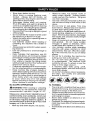
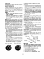
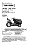
Mower
©
Mower Front Wheel
(2) Rear _
(5) I..3116
Lift Link
O.D. Washers
(1) Shoulder
Assemblies
Bolt
(1) 1-1/40.D.
Washer
%
(1) Small
Retainer
@
Springs
(1) Front _-_
Lift Link
_
Assembly
Retainer
(1) 3/8-16
Locknut
(1) Wheel
_
Springs
Slope Sheet
If Equipped
Keys
(2) Keys
(1) Anti-Sway
Bar
(1) 3/4 o.D.
Washers
(1) Small Retainer
Springs
(1) Quick
7
Connect
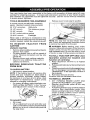
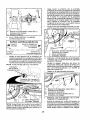
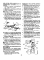
Your new tractor has been assembled at the factory with exception of those parts left unassembled for shipping purposes, To ensure safe and proper operation of your tractor all parts
and hardware you assemble must be tightened securely. Use the correct too]s as necessary
to ensure proper tightness.
TOOLS
REQUIRED
FOR ASSEMBLY
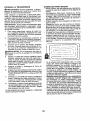
Release lever to lock seat in position.
A socket wrench set wi!l make assembly
easier. Standard wrench sizes are !isted.
(2) 7/16" wrenches
(1) 1/2" wrench
Utility knife
Tire pressure gauge
(1) 3/4" wrench
Pliers
(1) 3!4" socket w!drive ratchet
(1) 9/16" wrench
Flashlight
When right or left hand is mentioned in this
manual, _tmeans when you are in the operating
position (seated behind the steering wheel).
TO
REMOVE
CARTON
UNPACK
•
•
TRACTOR
NOTE: You may now roll your tractor off the
skid. Follow the appropriate instruction below
to remove the tractor from the skid.
FROM
WARNING; Before starting, read, understand and follow all instructtons inthe Operation
section of this manual. Be sure tractor is in a
well-ventilated area. Be sure the area in front
of tractor is clear of other people and objects.
CARTON
Remove all accessible loose parts and parts
cartons from carton.
Cut along dotted lines on all four panels of
carton. Remove end panels and lay side
panels flat.
Remove mower and packing materials.
Check for any additional loose parts or
cartons and remove.
BEFORE
REMOVING
FROM SKID
TO CHECK
TO ROLL TRACTOR OFF SKID (See
Operation section for location and
function of controls)
1.
Raise attachment lift lever to its htghest
position.
2. Release parkmg brake bydepressing brake
pedal,
3. Place freewheel control in disengaged position to disengage transmission (See "TO
TRANSPORT" in the Operation section of
this manual).
4. Roll tractor forward oft skid.
Continue with the instructions that follow.
TRACTOR
BA'rrERY
1. Lift hood to raised position.
NOTE: If this battery is put into service after
month and year indicated on label (label is
located between terminals) charge battery
for minimum of one hour at 6-10 amps. (See
"BA-FFERY" in Maintenance
section of this
manual for charging instructions).
•
For battery & battery cable installation see
"REPLACING BATTERY" in the "Service
and Adjustments" section in this manual.
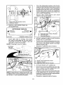
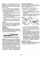
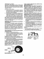
TO INSTALL
1.
•
MOWER
SET PARKING BRAKE LEVER AND
LOWER ATTACHMENT LIFT LEVER
Depress clutch!brake pedal all the way
down and hot&
Pull parking brake lever up and hold, release
pressure from clutch/brake pedal, then
release parking brake lever. Pedal should
remam in brake position. Ensure parking
brake wilt hold tractor secure.
Label
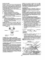
TO ADJUST S EAT
Sit in seat.
Lift up adjustment lever (A) and slide seat
until a comfortable posttion is reached which
allows you to press clutch/brake pedal all
the way down.
Brake Lever
8
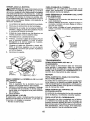
A_,CAUTION: Lift lever is spring loaded.
Have aught grip on lift lever, lower it slowty
and engage in lowest position, Lift lever is
located on left side of fender.
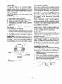
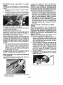
3. TURN STEERING WHEEL LEFT AND
POSITION MOWER
• Turn steedng wheel to the left as far as it
will go and position moweron right side of
tractorwithdeflector shield (Q)to the right.
L_
Lever
Front
_Engine
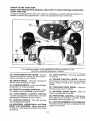
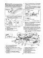
2. ASSEMBLE
FRONT
(W) TO FRONT
GAUGE
?
WHEEL
OF MOWER
_" l-ransaxle
Q. Deflector Shield
4. SLIDE MOWER
•
H.
W.
X
Y.
Z.
Front Mower Bracket
Front Gauge Wheel
Shoutder Bo_t
1-1/40 D. Washer
3/8-16 Locknut
A.
B.
C.
D.
E.
E
H.
Mower Side Suspension Arms
Retainer Spring
Rear Lift Link(S)
Right Side Rear Mower Bracket
Front Lift Unk Assembly
Front Suspension Bracket
Front Mower Bracket
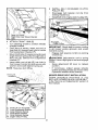
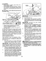
UNDER
TRACTOR
Bring beltforward and check beltforproper routing in all mower pulley grooves.
NOTE: Be sure mower side suspension
arms (A) are pointing forward before sliding
mower under tractor.
•
Slide mower under tractor
centered under tractor.
1.
K.
Left Side Rear Mower
Belt Tension Rod
L.
M.
Q.
Locking Bracket
Engine Clutch Pulley
Deflector Shield
S. Anti-Sway Bar
W. Front Gauge Wheel
Bracket
until
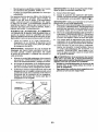
it is
Pivot the integrated washer end of antisway bar (S) towards mower deck bracket
on right side of mower. Insert integrated
washer end of bar into hole in rear mower
bracket (D). Move mower as needed to
insert integrated washer end of bar into
rear mower bracket (D).
Secure with small washer and small
retainer spring as shown.
A. Mower Side Suspension Arms
Q. Deflector Shield
(I
_
_
-____
0
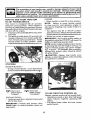
(IF EQUIPPED)
5,
I_(, ....>t'_-_Y'//tt.._
INSTALLANTI-SWAY
ANTI-SWAY
BAR (S)
(S)
BAR
'
I
___1!_
|
Towards
Transaxle
Towards ]]Db..I
Mower Deck
t
90 ° End
,/
Integrated Washer End I
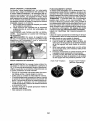
6. ATTACH MOWER SIDE SUSPENSION
ARMS (A) TO CHASSIS
• Position front holein side suspension arm
(A) over pin on outside of tractor chassis
and secure with large washer and large
retainer spring (B).
From right side of mower, first insert
90 ° end of anti-sway bar (S) into hole in
transaxle bracket (T), located near left
rear tire in front of transaxle.
NOTE: Flashlight
may be helpful.
An
Bar -Sway
(S)
_ .....
Location,
_-...........
L
i /
Repeat on opposite
it? i,..........""
'
I ,
"-, t i'-.
side of tractor.
',
y.-- ,-
Transaxle Bracket (T)
Located Between Rear Tires
A. Mower Side Suspension Arms
:B. Retainer Spnng
D. Right Side Rear Mower Bracket
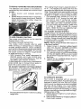
7.
ATTACH REAR LIFT LINKS (C)
Insert rod end of rear lift link (C) into hole
(U) in tractor lift shaft suspension arm
and pivot link down to mower.
Lift rear corner of mower and position slot
in link assembly over pin on rear mower
bracket (D) and securewith large washer
and large retainer spring.
NOTE: Depending on model, bracket (T)may
be different than shown but hole for anti-sway
bar will be in same position/location.
Repeat on opposite side of tractor.
10
9
INSTALL BELT ON ENGINE
PULLEY (M)
o
Disengage
belt tension
locking bracket (L).
CLUTCH
rod (K) from
Install belt onto engine clutch pulley (M),
C.
D.
'U.
8
Rear Lift Link(s)
Right Side Rear Mower
Hole
ATTACH
Bracket
FRONT LINK (E)
M.Engine
Clutch Pulley
Turn steering wheel to position wheels
straight forward.
From front of tractor, insert rod end of
front link (E) through front hole in tractor
front suspension bracket (F).
Moveto leftside of mower and and insert
large retainer spring (G) through hole in
front link (E) behind front suspension
bracket (F).
•
•
•
IMPORTANT: Check belt for proper routing
in all mower pulley grooves and under
mandrel covers,
Engage belt tension
bracket (L).
_kCAUTION:
Belt tension rod is spring
loaded. Have a tight grip on rod and engage
slowly.
Insert other end of link (E) into hole in
front mower bracket (H) and secure with
washer and small retainer spring (J).
NOTE; Requires
Front Link
Location
Raise attachment
position.
,
.
-'" _J
," ."- __
_- "
._ .'-_[__.._., _,.
f
tt [
,.
.....
,_
MOWER
.
j
DRIVE BELT INSTALLATION
Follow
procedure
described
in "TO
REPLACE MOWER BLADE DRIVE BELT"
in the "Service and Adjustments" section of
this manual.
/
".'L-.i
\
-.
R
G.
H.
J.
M.
lift lever to highest
If necessary,
adjust gauge
wheels
before operating mower as shown in the
Operation section of this manual.
deck lifting.
-
rod (K) on locking
Front Uft Unk Assembly
Front Suspension Bracket
Large Retainer Spring
Front Mower Bracket
SmaLl Retainer Spring
Engine Clutch Pulley
11
CHECK
TIRE
PRESSURE
The tires o n your tractor were overinflated at
the factory for shipping purposes.
Correct
tire pressure is important for best cutting
performance.
• Reduce tire pressure to PSI shown on
tires.
CHECK
DECK
For best
should be
MOWER"
section of
cutting results, mower housing
propedyleveled.
See"TO LEVEL
in the Service and Adjustments
this manual.
CHECK
FOR
ALL BELTS
LEVELNESS
PROPER
POSITION
BRAKE
Before you operate your new tractor, we
wish to assure that you receive the best
performance
and satisfaction
from this
Quality Product.
Please review the foJlowing checklist:
Vt All assembly instructions
have been
completed.
v" No remaining loose parts in carton.
J'Battery
is properly
prepared
and
charged,
i/Seat
is adjusted comfortably
and tightened securely.
OF
See the figures that are shown for replacing motion and mower blade drive belts nn
the Service and Adjustments section of this
manual.
Verify that the belts are routed
correctly.
CHECK
t_CHECKLIST
SYSTEM
After you learn how to operate your tractor,
check to see that the brake is operating
properly. See "TO CHECK BRAKE" in the
Service and Adjustments
section of this
manual.
J
All tires are properly inflated. (For shipping purposes, the tires were overinflated
at the factory).
J" Be sure mower deck is properly leveled
side-to-side/front4o-rear
for best cutting
results. (Tires must be properly inflated
for leveling).
J" Check mower and drive belts. Be sure
they are routed properly around pulleys
and rnside all belt keepers,
_/Check
wiring. See that all connections
are still secure and wires are properly
clamped.
,/Before
driving tractor, be sure freewheel
control is in "transmission engaged" position (see "To Transport" in the Operation
section of this manual).
While learning how to use your tractor, pay
extra attention to the following
important
items:
vt Engine oil is at proper level.
,/ Fuel tan k is filled with fresh, clean, regular
unleaded gasoline.
,/Become
familiar with all controls, their
location and function.
Operate them
before you start the engine.
€t Besure brake system is insafeoperating
condition.
v" Be sure Operator Presence System and
Reverse Operation System (ROS) are
working properly (See the Operation and
Maintenance sections in thns manual).
J" It is important to purge the transmission
before operating your tractor for the first
tim. e. Follow.proper
starting and transmission purging instructions
(See "TO
START ENGINE" and "PURGE TRANSMISSION" inthe 0 peration section of this
manual).
12
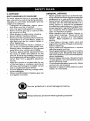
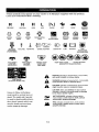
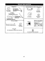
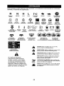
These
symbols
mayappear
onyourtractor
orinliterature
supplied
withtheproduct,
Learn
andunderstand
theirmeaning.
R
N
H
L
I\1
"_
REVERSE
NEUTRAL
HIGH
LOW
CHOKE
FAST
-_
SLOW
IGNITION
SWITCH
m
ENGINE
OFF
ENGINE
START
ENGINE
ON
DIFFERENTIAL
LOCK
CLUTCW
BRAKE PEDAL
PARKING
BRAKE
MOWER
HEIGHT
MOWER
LIFT
I.m.I
REVERSE
OPERATION
SYSTEM
(ROS)
REVERSE
FORWARD
CRUISE
CONTROL
UGHTS
ON
FUEL
BA'i-t'ERY
EAR
PROTEC_ON
RECOMMENDEO
®@@@@
A'_'ACHM ENT
CLUTCH
DISENGAGED
A'n'ACHMENT
CLUTCH
ENGAGED
DANGER. KEEP
HANDS AND
FEET AWAY
KEEP AREA CLEAR
SLOPE HAZARDS
(SEE SAFETY RULES SECTION)
&
&
&
FREEWHEEL
(Automatic Models onlyi
&
property
WARNING
indicates
could result
CAUTION
might
a hazard which, il not avoided,
or serious
Injury.
a hazard which,
In death or serious
indicates
a hazard
result in minor
to the tractor
snd/or
HOT SURFACES
=f net avoided,
injury.
wh=ch, if not ave=ded,
or moderate
injury.
engine,
sedous
indicates
a hazard which,
if not avoided, could result in death,
injury and/or property damage,
is used to identify safety informat_on about hazards which can
and/or
in death
injury or
death. The safety alert symbol
result in death,
indicates
will result
CAUTION when used without the alert symbol,
indicates a situation that could result in damage
Fai[ure to follow instructions
could result in serious
DANGER
FIRE indicates
could result
injury
property
damage.
13
serious
a hazard wh=ch, if not avoided,
in death,
damage.
serious
injury
and/or
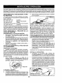
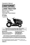
KNOW YOUR TRACTOR
READ THIS OPERATOR'S MANUAL AND SAFETY RULES BEFORE OPERATING
YOUR TRACTOR
Compare the illustrations with your tractor to familiarize yourself with the locations of
various controls and adjustments. Save this manual for future reference.
Our tractors
conform
American
to the applicable safety standards
National Standards Institute.
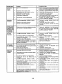
(A) ATTACHMENT
LIFT LEVER - Used to
raise and lower the mower or other attachments mounted to your tractor.
(B) BRAKE PEDALUsed for braking
tractor and starting the engine.
of the
(H) LIGHT SWITCH - Turns the headlights
on and off.
(J) CRUISE CONTROL LEVER - Used to
set forward movement of tractor at desired
speed without holding the forward drive
pedal.
the
(C) PARKING BRAKE- Locksclutch/brake
pedal into the brake position.
(D) THROTTLE/CHOKE
CONTROL- Used
for starting and controlling engine speed.
(E) ATTACHMENT
CLUTCH
SWITCH
- Usedto engagethe mower blades, or other
attachments
mounted to your tractor.
(K) FORWARD DRIVE PEDAL
forward movement of tractor.
- Used for
(L) REVERSE
DRIVE PEDALreverse movement of tractor.
Used for
(M) FREEWHEEL CONTROL- Disengages
transmission
for pushing or slowly towing
the tractor with the engine off.
(F) IGNITION SWITCH - Used for starting
and stopping the engine.
(P) SERVICE REMINDER/HOUR
METER
- Indicates when service is required for the
engine and mower.
(G) REVERSE
OPERATION
SYSTEM
(ROS) "ON" POSITION - Allows operation
of mower or other powered attach merit while
in reverse.
I4
The operation of any tractor can result in foreign objects thrown into
the eyes, which can result in severe eye damage,
Always wear safety
glasses or eye shields while operating your tractor or performing any
adjustments
or repairs. We recommend standard safety g|asses or a
wide vision safety mask worn over spectacles.
HOW
TO USE YOUR
TO SET PARKING
ENGfNE
TRACTOR
-
• Move throttle control (D) to slow position.
NOTE:
Failure to move throttle control
to slow position and allowing
engine to
idle before stopping may cause engine to
"backfire".
BRAKE
Your tractor is equipped with an operator
presence sensrng switch. When engine is
running, any attempt by the operator to leave
the seatwithout first setting the parking brake
will shut off the engine.
1. Depress brake pedal (B) allthewaydown
and hold.
2, Pull parking brake lever (C) up and hold,
release pressure from brake pedal (B),
then release parking brake lever. Pedal
should remain in brake position.
Make
sure parking brake will heldtractor secu re.
• Turn ignit=on key (F) to "STOP" position
and remove key. Always remove keywhen
leaving tractor to prevent unauthorized use.
• Never use choke to stop engine.
IMPORTANT:
Leaving the ignition switch in
any position other than "STOP" will cause the
battery to discharge and go dead.
NOTE: Under certain conditions when tractor
is standing idle with the engine running, hot
engine exhaust gases may cause "browning" of grass. To eliminate this possibility,
always stop engine when stopping tractor
on grass areas.
_I_CAUTION:
Always stop tractor completely, as described above, before leaving
the operator's position.
STOPPING
MOWER
BLADES
-
• To stop mower blades, move attachment
clutch control to disengaged position (_'t).
(1"_1)
Attachment
Clutch Control
"Engaged ....
(1_1)
Attachment
Clutch Control
D_sengaged"
TO USE THROI-rLE
CONTROL
(D)
Always operate engine at full speed (fast).
• Operating engine at less than full speed
(fast) reduces engine's operating
efficiency.
• Full speed (fast) offers the best mower
performance.
GROUND DRIVE • To stop ground drive, depress brake pedal
all the way down.
IMPORTANT:
Forward and reverse drive
pedals return to neutral position when not
depressed.
15
TO MOVE FORWARD
AND BACKWARD
The direction and speed of movement is
controlled by the forward and reverse drive
pedals.
1. Start tractor
and release
parking
brake.
2.
Slowly depress forward (K) or reverse(L)
drive pedal to begin movement, Ground
speed increases the further down the
pedal is depressed.
The cutting height range is approximately 1"
to 4% The heights are measured from the
ground to the blade tip with the engine not ru nning, These heights are approximate and may
vary depending upon soil conditions, height
of grass and types of grass being mowed.
• The average lawn should be cut to approximately
2-!/2" dunng the cool season and to over 3" during hot months,
For healthier and better looking lawns,
mow often and after moderate growth.
• For best cutting performance, grass over
6 inches in height should be mowed
twice. Make the first cut relatively high;
the second to desired height.
TO ADJUST
TO USE CRUISE
CONTROL
The cruise control feature can be used for
forward travel only.
SYSTEM CHARACTERISTICS
The cruise control should only be used
while mowing or transporting on relatively
smooth, straight surfaces. Other conditions
such as trimming at slow speeds may cause
the cruise control to disengage. Do not use
the cruise control on slopes, rough terrian
or while trimmimg or turning.
• With forward drive pedal depressed to
desired speed, pull cruise control lever
(J) up and hold while lifting your foot off
the pedal, then release the lever.
To disengagethe
cruise control, depress the
brake pedal, tap on forward drive pedal or
push the cruise control lever down.
TO ADJUST
MOWER
CU'rI-ING
The position of the attachment
determines the cutting height.
WHEELS
1. Adjust mower to desired cutting height
(See "TO ADJUST MOWER CUTTING
HEIGHT" in this section of manual).
2. With mower in desired heightofcut
position, gnu ge wheels should be assembled
so they are slightly off the ground. Install
gauge wheel in appropriate hole. TJghten
securely.
3. Repeat for all, installing gauge wheel in
same adjustment hole.
HEIGHT
lift lever (A)
TO OPERATE
• Putattachment
height slot.
GAUGE
Gauge wheels are properly adjusted when
they are slightly off the ground when mower
is at the desired cutting height in operating
position, Gauge wheels then keep the deck
in proper position to help prevent scalping
in most terrain conditions,
NOTE: Adjust gauge wheels with tractor on
a flat level surface.
MOWER
Your tractor is equipped with an operator
presence sensing switch. Any attempt bythe
operator to leave the seat with the engine
running and the attachment clutch engaged
will shut off the engine. You must remain
fully and centrally positioned in the seat to
prove nt the engine from hesitating or cutting
offwhen operatlngyour equipmenton rough,
rolling terrain or hills.
1. Select desired height of cut with attachment lift lever.
hft lever in desired cutting
2.
16
Start mower blades by engaging
ment clutch control.
attach-
TO STOP MOWER
• Disengage
BLADES
TO OPERATE
-
attachment clutch control.
,_CAUTION:
Do not operate the mower
without either the entire grass catcher, on
mowers so equipped, or the deflector shield
(S) in place.
REVERSE
OPERATION
SYSTEM
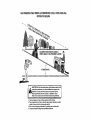
_L, WARNING:
Do not drive up or down
hills with slopes greater than 15 ° and do not
drive across any slope. Use the slope guide
provided at the back of this manual.
• Choose the slowest speed before starting
up or down hills.
• Avoid stopping or changing speed on hills,
• If stopping is absolutely necessary, push
brake pedal quickly to brake position and
engage parking brake.
• Torestartmovement,
slowfyreleaseparking brake and brake pedal.
• Slowly depress appropriate drive pedaf to
slowest setting.
• Make all turns slowly.
(ROS)
TO TRANSPORT
Your tractor is equipped with a Reverse
Operation System (ROS). Any attempt by
the operator to travel in the reverse direction
with the attachment clutch engaged will shut
off the engine unless ignition key is placed
in the ROS "ON" position,
When pushtng or towing your tractor, be
sure to dtsengage transmission
by placing
freewheel control in freewheeling
position.
Free wheel control is located at the rear
drawbar of tractor.
• Raise attachment lift to highest position
with attachment lift control.
• Pull freewheel control out and into the slot
and release so it is held in the disengaged
position.
• Do not push or tow tractor at more than
two (2) MPH.
• To reengage transmission,
reverse above
procedure.
,4_WARNING:
Backing up with the attachment clutch engaged while mowing is
strongly discouraged, Turningthe ROS "ON",
to allow reverse operation with the attachment clutch engaged, should only be done
when the operator decides it is necessary to
reposition the machine with the attachment
engaged. Do not mow in reverse unless
absolutely necessary.
USING
THE
SYSTEM -
REVERSE
OPERATION
Only use if you are certain no children or
other bystanders wdl enter the mowing area.
1. Depress brake pedal all the way down,
2. With engine running, turn ignition key
counterclockwise
to ROS "ON" position.
3. Look down and behind before and while
NOTE: To protect hood from damage when
transporting your tractor on a truck or atrailer,
be sure hood is closed and secured to tractor.
Use an appropriate means of tying hood to
tractor (rope, cord, etc.).
backing.
4, Slowly depress reverse drive pedal to
start movement.
5. When use of the ROSts
no longer
needed, turn the ignition key clockwise
to engine "ON" position,
ROS "ON" Pos_t_on
ON HILLS
TOWING
MENTS
CARTS
AND OTHER
A'I-FACH-
Tow only the attachments that are recommended by and comply with specifications
of the manufacturer of your tractor. Use
common sense when towing. Too heavy
of a load, while on a slope, is dangerous.
Tires can lose traction with the ground and
cause you to lose control of your tractor.
Engine "ON" Positron
(Normal Op_rattng)
17
SERVICE REMINDER/HOUR
METER
Service reminder shows the total number of
CAUTION:
Alcohol blended fuels (ca[led
gasohoI or using ethanol or methanol) can
attract motsture which ]ends to separation
and formation of acids during storage. Acidic
gas can damage the fuel system of an engine
while in storage. To avoid engine problems,
the fue! system should be emptied before
storage of 30 days or longer. Drain the gas
tank, start the engine and let it run until the
fuel hnes and carburetor are empty. Use
fresh fuel nextseason. See Storage Instructions for additional information. Never use
engine or carburetor cleaner products in the
fuel tank or permanent damage may occur.
hours the engine has run and indicates when
the engine or mower needs servicing. After
every 50 hours of operation the oil can icon
wi[[ stay on for 2 hours or until a manual reset
occurs. To reset the display manually turn
the ignition switch to the on position, then
the off position five times (1 second on, 1
second off). To service engine and mower,
see the Maintenance section of this man ual.
NOTE: Service
reminder runs when the
ignition key is in any position but "STOP".
For accurate reading, be sure key remains
Jn the "STOP" position when engine is not
running.
BEFORE
STARTING
THE
CHECK ENGINE OIL LEVEL
TO START
ENGINE
When starting the engine for the first time or
If the engine has run out of fuel, it will take
extra cranking time to move fuel from the
tank to the engine.
1. Be sure freewheel control Is in the transmisston engaged position.
2, Sit on seat in operating position, depress
brake pedal and set parking brake,
3. Move attachment clutch to disengaged
position.
4. Move throttle control to choke position.
NOTE: Before starting, read the warm and
cold starting procedures below,
5. Insert key into ignition and turn key
clockwise to start position and release
key as soon as engine starts. Do not run
starter contin uo usly for more than fifteen
seconds per minute. If the engine does
not start after several attempts, move
throttle control to fast position, wait a
few minutes and try again. If engine still
does not start, move the throttle control
back to the choke position and retry.
ENGINE
The engine in your tractor has been shipped,
from the factory, already filled with summer
weight oil.
1. Check engine oil with tractor on level
ground.
2. Remove oil fill cap!dipstick
and wipe
clean, reinsert the dipstick and screw cap
tight, wait for a few seconds, remove and
read oil level. If necessary, add oil until
"FULE' mark on dipstick is reached.
Do
not overfill.
• For coJd weather operation you should
change oil for easter starting (See the oil
viscosity chart in the Maintenance section
of this manual).
• To change engine oil, see the Maintenance
section in this manual.
• Fill fuel tank to bottom of filler neck. Do
not overfill.
Use fresh, clean, regular
unleaded
gasoline with a minimum
of
87 octane. (Use of leaded gasoline will
increase carbon and lead oxide deposits
and reduce valve life). Do not mix oil with
gasoline. Purchase fuel in quantities that
can be used withm 30 days to assure fuel
freshness.
_,CAUTION:
Wipe off any spilled oil or
fuel. Do net store, spill or use gasoline near
an open flame.
IMPORTANT:
When operating
in temperatures below 32 ° F(0 ° C), use fresh, clean
winter grade gasoline to help insure good
cold weather starting.
WARM WEATHER STARTING (50°F/10°C)
and above)
6. When engine starts, move the throttle
control to the fast position.
• The attachments
and ground drive can
now be used. Ifthe engine does not accept
the [oad, restart the engine and allow it to
warm up for one minute using the choke
as described above.
I8
PURGE TRANSMISSION
COLD
WEATHER
STARTING
(50°F(10°C)
andbelow)
Neverengage ordisengage
6. When
engine
starts,
leaveth
rottle
control _kCAUTION:
freewheel lever while the engine is running.
inchoke
position
untilengine
warms
up
andbegins
torunroughly.
Oncerough To ensure proper operation and performance,
running
begins,
immediately
move
the is recommended that the transmission be
throttle
control
tothefastposition.
Engine itpurged
operating tractor for the first
warm-up
maytake
fromseveral
secondstime. Thisbefore
procedure wt II remove any trapped
toseveral
minutes
(thecolder
thetem- air inside the transmission which may have
perature,
thelonger
thewarm-up). developed during shipping of your tractor.
AUTOMATIC
TRANSMISSION
WARM
UP IMPORTANT: Should your transmission
Before
driving
theunitincoldweather,
the require removal for service or replacement,
transmission
should
bewarmed
upasfol- it should be purged after reinstallation before
lows:
1. Besurethetractor
isonlevelground. operating the tractor.
Place tractor safely on a level surface 2. Release
theparking
brake
andletthe 1. that
of objects and open - with
brake
slowly
return
tooperating
position. engineis clear
off and parking brake set.
3. Allowoneminute
fortransmission
to
2. Disengage
transmission
by placing
warm
up.Thiscanbedoneduring
freewheel control in disengaged position
theengine
warm
upperiod.
(See "TO TRANSPORT"
in this section
• Theattachments
canalsobeuseddurmanual).
ingtheengine
warm-up
period
afterthe 3. ofSitttng
in the tractor seat, start engine.
transmission
hasbeenwarmed
up.
After the engine is running, movethrottle
control to slow position. Disengage
ing brake.
park-
_J_CAUTION:
At any ttme, during step 4,
there may be movement of the drivewheels.
4.
5.
6.
7.
8.
Depress forward drive pedal to full forward position and hold forfive (5) seconds
and release pedal. Depress reverse drive
pedal to full reverse position and hold
for five (5) seconds and release pedal.
Repeat this procedure three (3) times.
Shutoff engtne and set parking brake.
Engage transmission
by placing freewheel control in engaged position (See
"TO TRANSPORT"
in this section of
manual).
Sitting in the tractor seat, start engine.
After the engine is running, move throttle
control to half (I/2) speed. Disengage
parking brake.
Drive tractor forward for approximately
five feet then backwards for five feet.
Repeat
times.
this
driving
procedure
three
Your transmission is now purged and now
ready for normal operation.
19
MOWING
TIPS
• Tire chains cannot be used when the
mower housing is attached to tractor.
• Mowershould
be properlyleveledforbest
mowing performance.
See "TO LEVEL
MOWER HOUSING" in the Service and
Adjustments section of this manual.
• The left hand side of mower should be
used for trimming.
• Drive so thatclippings are discharged onto
the areathat has already been cut. Have
the cut area to the nght of the tractor. This
will result in a more even distribution of
clipptngs and more uniform cutting,
• When mowing large areas, start byturning
to the right so that clippings will discharge
away from shrubs, fences, driveways,
etc. After one or two rounds, mow in the
opposite direction making left hand turns
until fintshed.
f
lII _
• If grass is extremely
tall,it should be
mowed twice to reduce load and possible
fire hazard from dried clippings.
Make
first cut relatively high; the second to the
desired height.
• Do not mow grass when it is we'[. Wet
grass will plug mower and leave undesirable clumps. Allow grass to dry before
mowing.
• Always operate engine at full throttle
when mowing to assure better mowing performance
and proper discharge
of material.
Regulate ground speed by
selecting a low enough speed to give the
mower cutting performance as well as the
quality of cut desired,
• When operating attachments,
select a
ground speed that will suit the terrain and
give best performance of the attachment
being used.
2O
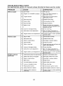
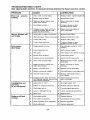
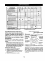
MAINTENANCE'
SCHEDULE
Check
B:akB
Check
T=re Pressure
V'
Op..e_ato;
Presence
Ch_ck
for I-RoSe
Fasteners
C
Check/Replace
T
LubrJcatton
0
Check
R
CleanBatteryandTerm;naJs
Mower
Clean
Dabr_s
& ROS
EVI_RY
lob
HOURS
EVERY
SF._SRN
BEFORE
5,'fORRG E
"
Systems
V _
_
i_
BI.ades
If
Ik##_
If
Check
Transax_e
Mower
Check
V-Belts
Check
Engm _ OLI Level
Engine
Cha_9_
Engine
V _
O.LI[with
o]1 biter)
Repla:e
Replace
,
GENERAL
Goohn_
Spark
,
1_2
If
Fins
,
,
_
2
.
If
2
Plug...
Atr Filter
Fd_l
,,_.,,..,
Paper Cartrldg_
i_
_=
Ft_er
V #
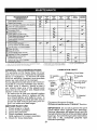
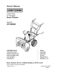
LUBRICATION
RECOMMENDATIONS
The warranty on this tractor does not cover
items that have been subjected to operator
abuse or negligence.
To receive full value
from the warranty, operator must maintain
tractor as instructed in this manual.
Some adjustments will need to be made periodically to properly maintain your tractor.
At least once a season, check to see if
you should make any of the adjustments
described in the Service and Adjustments
section of this manual,
• At least once a year you should replace
the spark plug, clean or replace air filter,
and check blades and belts for wear, A
EACH
CHART
(_)Steering
Spind[e_F--?_t_
@Front _-
_
Bearing
Zerk
"l_Steenng
Sector
Gear
Teeth
Pivot Bolts
_) Spindle
b_LJ_\ ....
Wheel
[-t:Lq
"10 FrontWheel
_.-.', _
,_'-_="
Beanng
_
_'@
_
,_
Zerk
I
Engine
"_
I I _i[i-I
t_,
I I :_ i;:_: I I\
II \ '-'_ t J l k
_ Mandrel
Zerks
new spark plug and clean air filter assure
proper air-fuel mixture and help your engine run better and fast longer,
BEFORE
f###
An-ester
oJI F=lt_r (Lf equipped)
Replace
If
V'l._.
Vf';t
Mufflet'lSpark
Engine
_t_'
Od [w=thout oil I_l_er}
Air Screen
C[Ban
V'
i/
clean
_lace
I_s
Levalness
G
Inspect
Plate
Cooling
Check
Chan_qe
k #_
Off Steering
Air Fdter
5.
EVERY
50
HOURS
V J'
Chart
Clean
1.
2.
3.
4.
EVERY
2,_
HOURS
Batter_ Le'_e!
NE
E
EVERY
8
HOURS
j
Check
U
BEFORe
EACR
use
Operation
A
I
........
OGeneral
Purpose Grease
(_)Refer to Mai ntenance "ENGI NE" Section.
USE
IMPORTANT:
Do not oil or grease the pivot
points which have special nylon bearings.
Viscous lubricants will attract dust and dirt
that will shorten the life ofthe self-lubricating
bearings, If you feelthey must be lubricated.
use only a dry, powdered graphite type
lubricant sparingly.
Check engine oil level.
Check brake operation.
Check tire pressure.
Check operator presence and
ROS systems for proper operation.
Check for loose fasteners.
21
TRACTOR
CHECK REVERSE
SYSTEM
Always observe safety rules when performing any maintenance.
BRAKE OPERATION
• Maintain proper air pressure in all tires
(See PSI on tires).
• Keep tires free of gasoline, oil, or insect
control chemicals which can harm rubber.
For best results mower blades must be sharp.
eplace worn, bent or damaged blades,
CAUTION:
Use only a replacement blade
approved by the manufacturer of yourtractor.
Using a blade not approved by the manufacturer of your tractor is hazardous, could
damage your tractor and void your warranty.
• Avoid stumps, stones, deep ruts, sharp
objects and other hazards that may cause
tire damage.
NOTE: To seal tire punctures and prevent
flat tires due to slow leaks, tire sealant may
be purchased from your local parts dealer.
Tire sealant also prevents tire dry rot and
corrosion.
OPERATOR
PRESENCE
SYSTEM AND
BLADE
PRESENCE
ROS "ON" Positron
REMOVAL
1.
Raise mower to highest position to allow
access to blades.
NOTE: Protect your hands with gloves and!
or wrap blade with heavy cloth.
2. Remove blade bolt by turning counterclockwise.
3. Install newbladewithstamped"THISSlDE
UP" facing deck and mandrel assembly.
IMPORTANT:
To ensure proper assembly,
center hole in blade must align with star on
mandrel assembly.
4. Install and tighten blade bolt securely
(45-55 Ft. Lbs. torque/65-75
Nm),
IMPORTANT:
Special blade bolt is heat
treated.
REVERSE OPERATION
SYSTEM (ROS)
Be sure operator presence and reverse
operation systems are working properly. If
you rtractor does not function as described,
repair the problem immediately.
• The engine should not start unless the
brake pedal is fully depressed, and the
attachment clutch control is in the disengaged position.
• When the engine is running,
by the operator to leave the
first setting the parking brake
off the engine.
• When the engine is running
tachment clutch is engaged,
by the operator to leave the
shut off the engine.
• Theattachmentclutch
should
ate unless the operator is in
(ROS)
• When theengineis running with theignition
switch in the engine "ON" position and the
attachment clutch engaged, any attempt
by the operator to shift into reverse should
shut off the engine.
• Whentheengineis
runningwiththe ignition
switch in the ROS "ON" position and the
attachment clutch engaged, any attempt
by the operator to shift into revers e should
NOT shut off the engine.
BLADE CARE
If tractor requires more than five (5) feet to
stop at highest speed in highest gear on a
level, dry concrete or paved surface, then
brake must be serviced. (See "TO CHECK
BRAKE" in the Service and Adjustments
section of this manual).
TIRES
CHECK OPERATOR
OPERATION
SYSTEM
any attempt
seat without
should shut
Star
and the atany attempt
seat should
neveroperthe seat.
(SpecEal_
Engine "ON" Position
(Normal Operating)
.-"
_-%._
........
BATTERY
Your tractor has a battery charging system
which is sufficient for normal use. However,
periodic charging of the battery with an automotive charger will extend its life.
• Keep battery and terminals
clean.
• Keep battery bolts tight.
• Keep small vent holes open.
• Recharge
22
at 6-t0 amperes
for 1 hour.
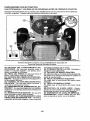
TO CHANGE ENGINE OIL
Determine temperature range expected
before oil change. All oil must meet API
service classification SG-SL.
NOTE: The original equipment battery on
your tractor is maintenance
free. Do not
attempt to open or remove caps or covers.
Adding or checking level of electrolyte is
not necessary,
TO CLEAN
BATTERY
• Be sure tractor is on level surface.
AND TERMINALS
• Oil will drain more freely when warm.
• Catch oil in a suitable container.
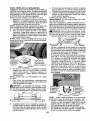
Corrosion and dirt on the battery and terminals can cause the battery to "leak" power.
1. Removetermlnat
guard.
2, Disconnect
BLACK battery cable first
then RED battery cable and remove
battery from tractor.
3. Rinsethebatterywith
plainwateranddry.
4. Clean terminals and battery cable ends
with wire brush until bright.
5. Coatterminals
with grease or petroleum
jelly.
6. Reinstall
battery
(See "REPLACING
BATTERY" in the SERVICE AND ADJUSTMENTS
section of this manual).
V-BELTS
CheckV-belts
for deterioration
1. Remove oil fill cap/dipstick.
Be careful
not to allow dirt to enter the engine when
changing oil,
2. Slide oil drain extension from the docking
position on the engine blower housing
and extend outward from engine.
Docking
Position
Oil Drain
and wearafter
100 hours of operation and replace if necessary. The belts are not adjustable, Replace
belts if they begin to slip from wear.
ENGINE
3. To open, twist cap counter-clockwise
LUBRICATION
4, After oil is drained completely, replace
cap and twist clockwise until it stops.
Only use high quality detergent oil rated with
API service classification SG-SL, Selectthe
oil's SAE viscosity grade according
expected operating temperature.
.
T_t
Pt=R&FU R E RANG
E ANTIGIPATE
D BE FO F_E N_F
5.
Re-attach oil drain extension
blower housing.
6.
Refi[tengine with oilthrough oilfill dipstick
tube. Pour slowly. Do not overfill For approximate capacity see "PRODUCT SPECIFICATIONS"
section of this manual.
to your
OIL _l'_r.L_
to engine
7. Use gauge on oil fill cap/dipstick
for
checking level. For accurate reading,
tighten dipstick cap securely onto the
tube before removing dipstick. Keep oil
at "FUL_ line on dipstick. Tighten cap
onto the tube securely when finished.
I
NOTE: Although multi-viscosity oils (5W30,
10W30 etc.) improve starting in cold weather,
they will result in increased oil consumption
when used above 32°F/0°C.
Check your
engine oil level more frequentlyto avoid possible engine damage from running low on oil.
Change the oil after every 50 hours of ope ration or at least once a year if the tractor is
not used for 50 hours in one year.
Check the crankcase oil level before starting
the engine and after each eight (8) hours
of operation.
Tighten oil fill cap/dipstick
securely each time you check the oi! level
ENGINE
OIL FILTER
Replace the engine oil filter every season or
every other oil change if the tractor is used
more than 100 hours in one year,
23
AIR FILTER
CLEAN
Your engine w_fl not run properly using a
dirty air filter, Clean the foam pre-cleaner
after every 25 hours of operation or every
season. Service paper cartridge every 100
hours of operation or every season, whichever occurs first.
Service air cleaner more often under dusty
conditions.
1. Remove cover,
Air screen must be kept free of dirt and chaff
to prevent engine damage from overheating.
Clean with a wire brush or compressed airto
remove dirt and stubborn dried gum fibers.
TO SERVICE
Every 100 hours of operation (more often
under extremely
dusty, dirty conditions),
remove the blower he using and other cooling
shrouds. Clean the cooling fins and external
surfaces as necessary. Make surethe cooling
shrouds are reinstalled.
NOTE;
Operating the engine with a blocked
grass screen, dirty or plugged cooling fins,
and/or cooling shrouds removed will cause
engine damage due to overheating.
MUFFLER
PRE-CLEANER
2. Wash it in liquid detergent and water.
3, Squeeze it dry in a clean cloth,
4. Saturate it in engine oil. Wrap it in clean,
absorbent cloth and squeeze to remove
excessoil.
NOTE: If very dirty or damaged,
replace
pre-cleaner.
TO SERVICE
CARTRIDGE
1. Clean cartridge by tapping gently on flat
surface, Ifvery dirty ordamaged,
replace
cartridge.
2. Reinstalf precleaner cartridge, cover and
secure.
IMPORTANT:
Petroleum solvents, such as
kerosene, are not to be used to clean the
cartridge.
They may cause deterioration of
the cartridge.
Do not oil cartridge.
Do not
use pressurized alrto clean or dry cartridge.
CLEAN
AIR SCREEN
AIR INTAKE/COOLING
AREAS
To ensure proper cooling, make sure the
grass screen, cooling fins, and other external surfaces of the engine are kept clean
at all times.
Inspect and replace corroded muffler and
spark arrester (if equipped) as it co uld create
a fire hazard and/or damage.
SPARK PLUG(S)
Replace spark plug(s) at the beginning of
each mowing season or after every 100
hours of operation, whichever occurs first.
Spark plug type and gap setting are shown
in "PRODUCT SPECIFICATIONS"
section
of this manual.
IN-LINE
FUEL FILTER
The fuel filter should be replaced once each
season. If fuel filter becomes clogged, obstructing fuel flow to carburetor, replacement
is required.
1. With engine cool, remove filter and plug
fuel ]ine sections.
q_;-_-_
Pre-Cleaner
Cartridge
2, Place new fuel filter Jn position in fuel line
with arrow pointing towards carburetor.
3. Be sure there are no fuel line leaks and
clamps are properly positioned.
4. Immediately wipe up any spilled gasoline,
i _._
Clam_amp
Fuel Filter
24
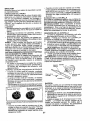
CLEANING
• Clean engine, battery, seat, finish, etc.
of all foreign matter.
Clean debris from steering plate. Debris
can restrict clutch!brake pedal shaft
movement, causing belt slip and loss of
drive.
-& CAUTION: Avoid all pinch points and
movable parts
0._
Clutch!brake
pedal
IMPORTANT:
Tug hose ensuring
tion is secure.
5.
Turn the water on,
connec-
6.
Steering System, Dash,
Fender and Mower I_ot Shown
CAUTION:
,_
Pinch
_
Points
Keep finished surfaces and wheels
free of all gasoline, oil, etc.
Protect painted surfaces with automotive type wax.
We do not recommend using a garden hose
or pressure washer to clean your tractor
unless the engine and transmission
are
covered to keep water out. Water in engine
or transmission will shorten the useful life of
your tractor. Use compressed air or a leaf
blower to remove grass, leaves and trash
from tractor and mower.
DECK WASHOUT
PORT
Your tractor's
deck is equipped
with a
washout port on its surface as part of its
deck wash system. It should be utilized after each use.
1.
Drive the tractor to a level, clear spot
on your lawn, near enough to a water
spigot for your garden hose to reach.
IMPORTANT:
Make certain the tractor's
discharge chute is directed AWAY from your
house, garage, parked cars, etc. Remove
bagger chute or mulch cover if attached.
2.
Make s urethe attachment clutch control
is in the "DISENGAGED"
position, set
the parking brake, and stop the engine.
3.
Thread the nozzle adapter (packaged
with your tractor's Operator's Manual)
onto the end of your garden hose.
4.
Pull back the lock collar of the nozzle
adapter and push the adapter onto the
deck washout port at the left end of the
mower deck. Release the lock collar to
lock the adapter on the nozzle.
While sitting in the operator's position
on the tractor, re-start the engine and
place the throttle lever in the Fast ",{_"
position,
IMPORTANT:
Recheck the area making
certain the area is clear.
7.
Move the tractor's attachment clutch
control
to the "Engaged"
position,
Remain in the operator'sposition
with the cutting deck engaged until the
deck is cleaned.
8.
Move the tractor's attachment
clutch
control to the "DISENGAGED"
position. Turn the ignition key to the STOP
position to turn the tractor's engine off.
Turn the water off.
9.
Pull back the lock collar of the nozzle
adapter to disconnect the adapter from
the nozzle washout port.
10. Move the tractor to a dry area, preferably a concrete or paved area. Place
the attachment
clutch control in the
"Engaged" position to remove excess
water and to help dry before putting the
tractor away.
A(_WARNING: A broken or missing washout
fitting could expose you or others to thrown
objects from contact with the blade.
• Replace broken or missing washout fitting
immediately, prior to using mower again.
• Plug any holes in mower with bolts and
Iocknuts.
25
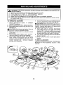
WARNING:
TOAVOID
SERIOUS
INJURY,
BEFORE
PERFORMING
ANY
SERVICE
OR
ADJUSTMENTS:
.
•
4,
5.
6.
Depress clutch/brake
pedal fully and set parking brake.
Place attachment clutch in "DISENGAGED"
position.
Turn ignition key to "STOP" and remove key.
Make sure the blades and all moving parts have completely stopped.
Disconnect spark plug wire from spark plug and place wire where it cannot come
in contact with plug,
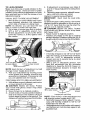
TO REMOVE
MOWER
7.
1. Place attachment
clutch in "DISENGAGED" position,
2. Lower attachment lift to lowest position.
3. Disengage belttension rod (K) from lock
bracket (L).
_L, CAUTION: Rod is spring loaded, Have a
tight grip on rod and release slowly.
4. Remove mower belt from electric clutch
pulley (M).
5. Disconnect front link (E) from mower remove retainer spring and washer.
6, Go to either side of mower and disconnect mower suspension
arm (A) from
chassis and rear lift link (C) from rear
mower bracket (D) - remove retainer
springs and washers.
26
Go to otherside of mowerand disconnect
the suspension arm and rear lift link.
_k CAUTION: After rear hft links are disconnected, the attachment lift lever will be spring
loaded. Have a tight grip on lift lever when
changing position of the lever,
8. From right side of mower, disconnect
anti-sway bar (S) from right rear mower
bracket (D) _ remove retainer spring and
washer and pull mower toward you until
the bar falls from the hole in bracket.
9. Turn tractor steering wheel to the left as
far as it will go.
10. Slide mower out from under right side of
tractor.
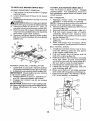
TO INSTALL MOWER
Follow procedure des cribed in "TO IN STALL
MOWER" in the Assembly section of this
manual.
TO LEVEL MOWER
Make sure tires are properly inflated to the
PSI shown on tires. If ttres are over or under
inflated, it may affectthe appearance of your
lawn and lead you to think the mower is not
adjusted properly.
VISUAL
SIDE-TO-SIDE
4.
If adjustment is necessary, see steps 2
and 3 in VisuaL Adjustment instructions
above.
5. Recheck measurements, adjust if necessary until both sides are equal.
FRONT-TO-BACK
ADJUSTMENT
IMPORTANT:
Deck must be level sideto-side.
To obtain the best cutting resutts, the mower
blades should be adjusted so the front tip is
1/8" to 1[2" lower than the rear tip when the
mower is in its highest position.
CAUTION:
Blades are sharp. Protect
your hands with gloves and/or wrap blade
with heavy cloth.
• Raise mower to highest position.
• Position any blade so the tip is pointing
straight forward. Measure distance (B) to
the ground atfront and reartip ofthe blade.
ADJUSTMENT
1. With all tires properly inflated and tf your
lawn appears unevenly cut, determine
which side of mower is cutting lower.
NOTE: As desired, you can raise the low
side of mower or lower the high side.
2. Go to side of mower you wish to adjust.
3. With a 3/4" or adjustable wrench, turn
tilt link adjustment
nut (A) to the left to
lower the mower, or, to the right to raise
the mower.
°o\\
Turn nut dgh_
to raise mower
• Iffronttip
of blade is not 1/8" to 1/2" lower
than the rear tip, go to the front of tractor.
• With an 11/16" or adjustable
wrench,
loosen jam nut A several turns to clear
adjustment nut B,
• With a 3/4" or adjustable wrench, turn
front link adjustment
nut (B) clockwise
(Itighten) to raise the front of mower, or,
counterclockwise
(loosen) to lower the
front mower.
Turn nut left
to lower mower
NOTE: Each full turn of adjustment nut will
change mower height about 3/16".
4. Test your adjustment
by mowing some
uncut grass and visuatty checking the
appearance. Readjust, if necessary, until
you are satisfied with the resufts.
PRECISION
SIDE-TO-SIDE
++
ADJUSTMENT
1. With alltires properlyinflated,
parktractor
on level ground or driveway.
_k CAUTION:
Blades are sharp. Protect
your hands with gloves and/or wrap blade
with heavy cloth.
2. Ratse mower to its highest position.
3. At both s_des of mower, position blade at
side and measure the distance (A) from
bottom edge of blade to the ground. The
distances houtd bethesameon
both sides.
Tighten adjust nut
B to raise mower
Loosen adjust
nut B to lower
mower
Loosen jam nut A first
NOTE: Each full turn of the adjustment nut
will change mower height about 1/8".
• Recheck measurements,
adjust if necessary until front tip of blade is 1/8" to 1/2"
lower than the rear tip.
• Hold adjustment nut in position with wrench
and tighten jam nut securely against adjustment nut.
27
TO REPLACE
MOWER
1.
2.
3.
ed.
4.
5.
6.
DRIVE
MOWER
DRIVE BELT
TO REPLACE
MOTION
BELT REMOVAL
Park tractor on a level surface. Engage
parking brake.
Lower attachment lift lever to its lowest
BELT REMOVAL
position.
Disengage be[ttension rod (K) from lock
bracket (L).
CAUTION: Belttension red isspnngloadHave afirm grip on rod and release slowly.
Remove screws (P) from R.H, and L.H.
mandrel covers and remove covers (Q).
Remove any dirt or grass clippings which
may have accumulated around mandrels
and entire upper deck surface.
Remove belt from electric clutch pulley
(M), both mandrel pulleys (R) and all idler
pulleys (S),
-
1, Remove mower (See "TO REMOVE
MOWER" in this section of manual).
NOTE: Observe entire motion drive belt and
position of all belt guides and keepers.
2. Remove beltfrom stationary idler (A) and
clutching Idler (B).
3. Remove belt from centerspan idler (C),
4. Pull belt slack toward rear _)f tractor.
Carefully
remove belt upwards
from
transmission input pulley and over cooling fan blades (D).
5. Remove belt downward
from engine
pulley (E).
6, Slide belt toward rear of tractor, off the
steering plate (F) and removefromtractor.
BELT INSTALLATION
MOWER
DRIVE BELT
Park the tractor on level surface.
Engage
parking brake.
For assistance, there is a
belt installation guide decal on bottom side
of left footrest.
-
1. install new belt from tractor rear to front,
over the steering plate (F) and above
clutch brake pedal shaft (G),
2, Pull belt toward front of tractor and roll
belt onto engine pulley (E).
3. Pull belt toward rear of tractor. Carefully
work belt down around transmission
cooling fan and onto the input pulley (D).
Be sure belt is inside the belt keeper.
4, Install belt on centerspan idler (C).
5. Install belt through stationary idler (A)
and clutching idler (B).
6. Make sure belt is in all pulley grooves
and inside all belt guides and keepers.
7. Instali mower (See"TO INSTALL MOWER" in this section of manual).
DRIVE BELT INSTALLATION
1. Install belt around both mandrel pulleys
(R) and around idler pulleys (S) as shown.
2. Install belt onto electric clutch pulley (M).
IMPORTANT:
Check belt for proper routing
in all mower pulley grooves.
3. Reassemble R.H, and L.H. mandrel covers (Q), Securely tighten all screws.
4. Engage belt tension rod (K) on locking
bracket (L).
& CAUTIO N: Belt tension rod is spring loaded. Have at,ight grip on rod and engage slowly,
5. Raise attachment
lift lever to highest
position.
28
TO CHECK BRAKE
If tractor requires more than five (5) feet tO
stop at highest speed in highest gear on a
level, dry concrete or paved surface, then
brake must be serviced,
You may also check brake by:
1. Park tractor on a level, dry concrete or
paved surface, depress brake pedal all
the waydown and engage parking brake.
2. Disengage transmission by placing
freewheel control in '3ransmission disengaged" position,Pullfreewheel control
out and into the slot and release so it is
held in the disengaged position.
The rear wheels must lock and skid when
you try to manually push the tractor forward,
If the rear wheels rotate, then the brake
needs to be serviced. Contact a Sears or
other qualified service center.
FRONT WHEEL TOE-IN/CAMBER
Your new tractor front wheel toe-in and camber is set at the factory and is normal. The
front wheel toe-in and camber are not adjustable. If damage has occurred to affect the
factory set front wheel toe-in or camber, contacta Sears or other qualifiedservice center.
TO REMOVE WHEEL FOR REPAIRS
1. Block up axle securely.
2. Remove axle cover, retaining ring and
washers to allow wheel removal (rear
wheels have a square key-Do not lose).
3, Repair tire and reassemble,
NOTE: On rearwheels only: align grooves in
rear wheel hub and axle. Insert square key.
4. Replace washers andsnap retaining ring
securely in axle groove.
5. Replace axle cover.
NOTE: To seal tire punctures and prevent
flat tires due to slow leaks, purchase and
use tire sealant from Sears. Tire sealant also
prevents tire dry rot and corrosion.
TO START ENGINE WITH A WEAK BATTERY
_IkWARNING: Lead-acid batteries generate explosive gases. Keep sparks, flame
andsmoking materials away from batteries.
Always wear eye protection when around
batteries.
tfyour batteryistoo weakto startthe engine,it
should be recharged. (See "BATTERY" inthe
MAINTENANCE section of this manual),
If "jumper cables" are used for emergency
starting, follow this procedure:
IMPORTANT: Your tractor is equipped with
a 12volt system. The other vehicle must also
be a 12 volt system, Do not use your tractor
battery to start other vehicles.
TO ATTACH JUMPER CABLES
1. Connect one end of the RED cableto the
POSITIVE (+) terminal of each battery(AB),taking care notto short against tractor
chassis.
2. Connect one end of the BLACK cable
to the NEGATIVE (-) terminal (C) of fully
charged battery.
3. Connect the other end of the BLACK
cable (D) to good chassis ground, away
from fuel tank and battery.
TO REMOVE CABLES, REVERSE
ORDER
1. BLACK cable first from chassis and then
from the fully charged battery.
2. RED cable last from both batteries.
Weak or Dead
Battery
Washers
Retaining
Ring
Axle Cover
_Square
Key (Rear
Wheel Only)
29
FullyCharged
Battery
REPLACING
BA'n-ERY
TO REMOVE HOOD AND GRILL
ASSEMBLY
1. Raise hood.
n_asWARNING:
Do not short battery termiby allowing a wrench orany other object
to contact both terminals at the same time.
Before connecting
battery, remove metal
bracelets, wristwatch bands, rings, etc.
Positive terminal must be connected first to
prevent sparking from accidental grounding.
2. Unsnap headlight wire connector.
3. Stand in front of tractor. Grasp hood at
sides, tilt toward engtne and lift off of
tractor.
4. When replacing hood, be sure to reconnect the headlight wire connector.
I. Lift hood to raised position.
2. Remove terminal cover.
3.
Disconnect
BLACK battery cable then
RED battery cable and carefully remove
battery from tractor.
4.
Installnewbatterywithterminalstnsame
position as old battery.
5, Reinstall terminal cover.
6.
First connect RED battery cableto positive (+) battery terminal with bolt and nut
as shown. Tighten securely.
7.
Connect
BLACK grounding
cable to
negabve (-) battery terminal with remaining bolt and nut. Tighten securely
8. Close hood.
TRANSMISSION
REMOVAL/REPLACEMENT
Negative
..
__
Terminal
Should your transmission require removalfer
service or replacement, it should be purged
after reinstatlation and before operating the
tractor. See "PURGE TRANSMISSION"
in
the Operation section of this manual.
(Black)
Gable
_
covor
Posttive_1"_
(Red)--"
Cable
_'_,_a_L_"
"__
"_.., _
\_v-'_i/-
)
ENGINE
/_
TO ADJUST
CABLE
THRO'I-I'LE
CONTROL
The throttle control has been preset at
the factory and adjustment should not be
necessary Check adjustment as described
below before loosening cable. If adjustment
is necessary, see engine manual.
TO ADJUST CHOKE CONTROL
TO REPLACE HEADLIGHT
BULB
1. Raise hood.
2. Remove bulb holder from the hole in the
backside of the grill,
Replace bulb in holder and install bulb
holder securely back into the hole in the
backside of the grill.
4. Close hood.
INTERLOCKS
AND RELAYS
3.
The choke control has been preset at
the factory and adjustment should not be
necessary, tf adjustment is necessary, see
engine manual.
TO ADJUST CARBURETOR
Loose or damaged wiring may cause your
tractor to run poorly, stop running, or prevent
it from starting.
• Check wiring.
TO REPLACE FUSE
Your carburetor has been preset atthe factory
and adjustment should not be necessary,
However, minoradjustment
may be required
to compensate for differences in fuef, temperature, altitude or load. If the engine does
need adjustment, see engine manual.
Replace with 30 amp automotive-type
plugin fuse, The fuse holder is located behind
the dash.
30
ENGINE
Immediately prepare your tractor for storage
at the end of the season or if the tractor will
FUEL SYSTEM
not be used for 30 days or more.
_WARNING:
IMPORTANT:
It is important to prevent
gum deposits from forming in essential fuel
system parts such as carburetor, fue! hose,
or tank dunng storage. Also, alcohol blended
fuels (called gasohol or using ethanol or
methanol) can attract moisture which leads
to separation and formation of acids during
storage. Acidic gas can damage the fuel
system of an engine while in storage,
• Empty the fuel tank by starting the engine
and letting it run until the fuel lines and
carburetor are empty.
• Never use engine or carburetor cleaner
products in the fuel tank or permanent
damage may occur.
• Use fresh fuel next season.
NOTE:
Fuel stabilizer is an acceptable alternative in minimizing the formation of fuel
gum deposits during storage. Add stabilizer
to gasoline in fuel tank or storage container.
Always followthe mix ratio found on stabilizer
container.
Run engine at least 10 minutes
after addi ng stabilizerto allow the stabilizerto
reach the carburetor. Do not empty the gas
tank and carburetor if using fuel stabilizer.
ENGINE OIL
Never storethetractorwith
gasoline in the tank inside a building where
fumes may reach an open flame or spark.
Allow the engine to cool before storing in
any enclosure.
TRACTOR
Remove
mower from tractor for winter
storage. When mower is to be stored for a
period of time, clean it thoroughly, remove
all dirt, grease, leaves, etc. Store in acfean,
dry area.
1. Clean entire tractor (See "CLEANING"
in the Maintenance
section
of this
manual).
2. Inspect and replace belts, if necessary
(See belt replacement instructions in the
Service and Adjustments section of this
manuat).
3. Lubricate as shown in the Maintenance
section of this manual.
4. Be sure that all nuts, bolts and screws
are securely fastened.
Inspect moving
parts for damage, breakage and wear.
Replace if necessary.
5. Touch up all rusted or chipped paint
surfaces; sand lightly before painting.
Drain oil (with engine warm) and replace
with clean engine oil. (See "ENGINE" in the
Maintenance section of this manual).
CYLINDER(S)
1. Remove spark plug(s).
2. Pour one ounce ofoil through spark plug
hole(s) into cylinder(s).
3. Turn ignition key to "START" position for
a few seconds to distribute oil.
4. Replace with new spark plug(s),
BAI-rERY
• Fully charge the battery for storage,
• After a period of Lime in storage, battery
may require recharging.
• To help prevent corrosion and power leakage during long periods ofstorage, battery
cables should be disconnected
and battery cleaned thoroughly (see "TO CLEAN
BATTERY
AND TERMINALS"
in the
Maintenance
section of this manual).
• Aftercleaning,
leavecables disconnected
and place cables where they can not come
in contact with battery terminals.
• tf battery is removed
from tractor for
storage, do not store battery directly on
concrete or damp surfaces.
OTHER
• Do not store gasoline from one season to
another.
• Replace your gasoline can if your can starts
to rust. Rust and/or dirt in your gasoline
wilt cause problems.
• If possible, store your tractor indoors and
coveritto give protection from dust and dirt.
• Cover your tractor with a suitable protective cover that does not retain moisture.
Do not use plastic. Plastic cannot breathe
which allows condensationto
form and will
cause your tractor to rust.
IMPORTANT:
Never cover tractor while
engine and exhaust areas are still warm.
31
TROUBLESHOOTING CHART:
See appropriate section in manual unless directed to Sears service center
PROBLEM
Will
not
start
CAUSE
Out of fuel.
1
Fill fue[tank.
Engine not "CHOKED"
2
See "TO START ENGINE" in
Operation section.
Engine flooded.
3
Wait several minutes before
attempting to start.
4
Bad spark plug
4
Replace spark plug.
5
Dirty air filter.
5
Clean/replace
6
Dirty fuel f_lter.
6
Replace fuel filter.
7
Water in fuel.
7
Empty fuel tank and carburetor,
refill tank with fresh gasoline and
replace fuel filter.
8
Loose or damaged wiring.
B
Check altwlnng.
9
Carburetor
9
See "To Adjust Carburetor" in
Service and Adjustments sectton.
10
Contact a Sears or ether qualff=ed
service center.
1
2
3
10
Hard to start
Engine will not
turn over
CORRECTION
properly.
out of adiustment.
Engine valves out of adiustment.
a=r filter.
1
Dirty air filter•
1
Clean!replace
2
Bad spark plug.
2
Replace spark plug.
3
Weak or dead battery.
3
Recharge or replace battery.
4
Dirty fuel filter.
4
Replace fuel filter.
5
Stale or dirty fuel.
5
Empty fuel tank and refill tank witl
fresh, clean gasoEine.
6
Loose or damaged wiring.
6
Check all wiring_
7
Carburetor
7
See "1-oAdjust Carburetor" in
Service and Adjustments section.
8
Engine valves out of adjustment.
8
Contact a Sears or other qualtfled
service center,
1
Clutch/brake
1
Depress clutch!brake
2
Attachment
2
Disengage
3
Weak or dead battery
3
Recharge or replace battery,
4
Blown fuse.
4
Replace fuse.
5
Corroded battery terminals.
5
Clean battery terminals.
6
Loose or damaged wlnng.
6
Check all wiring.
7
Faulty ignition switch.
7
Check/replace
ignition switch.
8
Faulty solenoid or starter.
8
Check/replace
solenoid or starter.
9
Faulty operator presence
swltch(es).
9
Contact a Sears or other quahfied
service center.
out of adjustment.
pedal not depressed
clutch is engaged•
32
air filter.
pedal.
attachment
clutch.
TROUBLESHOOTING CHART:
See appropriate section in manual unless directed to Sears service center
PROBLEM
Engine clicks but
will not start
Loss of power
Excessive
CORRECTION
CAUSE
vibration
Engine continues
tc
run when operator
leaves seat with
attachment
clutch
1
Weak or dead battery.
1
Recharge or replace battery,
Corroded battery terminals.
2
Clean battery term=nals.
3
Loose or damaged wiring.
3
Check all wtring.
4
Faulty solenoid or starter.
4
Check/replace
1
Cutting too much grass!too fast.
1
Raise cutting hetght/reduce
speed.
2
Throttle in "CHOKE"
2
position.
12
13
solenoid or starter. I
Adjust throttle control
Clean underside
housing.
of mower
3
Build-up of grass, leaves and
rash under mower.
4
Dirty air filter.
4
Clean/replace
5
Low oil levelidtrty oil.
5
Check oil level/change
6
Faulty spark plug.
6
Clean and regap or change
plug.
7
Dirty fuel filter.
7_ Replace fuel filter.
8
Stale or d=rty fuel.
a
9
Water =nfuel.
air filter.
oil.
spark
Empty rue! tank and refill tank w_th
fresh, clean gasoline.
Empty fuel tank and carburetor,
refiEltank with fresh gasoline and
replace fuel filter.
10
Spark plug wire loose.
10
Connect and t=ghten spark plug
wire.
11
Dirty engine air screen/fins.
11
Clean eng=ne air screen/fins.
12
Dirty/c!ogged
12
Clean!replace
Check all wiring.
muffler.
muffler.
13
Loose or damaged wiring.
13
14
Carburetor
14
See "To Adjust Carburetor" in
Service and Adjustments section.
15
Engine valves out of adjustment.
15
Contact a Sears or other qualified
service center.
out of adjustment.
1
Replace blade. Tighten blade bo_t
2
Bent b]ede mandrel.
2
Contact a Sears or other
qualified service center.
3
Loose]damaged
3
Tighten loose' part[s).
Replace damaged parts.
!
Faulty operator-safety
control system
1
i Woe,
bent or loose blade.
part(s).
engaged
33
presence
;1
Check w=ring, switches and
connections. If not corrected,
contact a Sears or other qualified
servicecenter.
TROUBLESHOOTING CHART:
See appropriate section in manual unless directed to Sears service center
CAUSE
PROBLEM
Poor cut - uneven
cutting
Mower blades will
not rotate
CORRECTION
1
Worn, b_nt or loose blade.
1
2
Mower deck not level.
2
Level mower deck.
3
Buildup of grass, leaves, and
trash under mower,
3
Clean underside of mower
housmg.
4
Sent blade mandrel.
4
Contact a Sears or other
qualified service center.
5
Clogged mower deck vent from
butfd-up of grass, leaves, and
trash around mandrels.
5
Clean around mandrels to
open vent holes.
1
Obstruction
1
Remove obstruction.
2
Worn/damaged
3,
Frozen idler pulley.
3
Replace idler pulley.
4
Frozen blade mandrel,
4
Contact a Sears or other
qualtfied servtce center.
Engine speed too slow.
1
Place throttle control tn 'FAST"
position.
2
Travel speed too fast,
2
Shpftto slower speed.
Poor grass
discharge
in clutch mechantsm.
mower drive beJt 2
Replace blade. Tighten biade bolt
Replace mower drive belt.
3
Wet grass.
3
Allow grass to dry before mowpng
4
Mower deck not tevel.
4
Level mower deck.
5
Low/uneven
5
Check tires for proper PSI.
6
Worn, bent orloose
6
Replace/sharpen
blade bolt.
7
Buildup of grass, leaves and
trash under mower.
7
Clean underside of mower
housing.
tire air pressure.
blade.
blade. T£ghten
8
Mower drive belt worn.
8
Replace mower drive belt.
9
Blades improperly
9
Reinstal_ blades sharp edge down
10
Improper blades used.
11
Clogged mower deck vent holes
11
from buildup of gras& leaves, and
trash around mandrels.
Clean around mandrels
open vent holes.
tnstailed
10
Replace with blades listed In
this manual.
to
not
1
Lpght switch ts "OFF".
1
Turn light switch "ON"
(if so equipped)
2
Bulb(s) or lamp(s) burned out.
2
Replace bulb(s) or lamp(s).
3
Faulty light switch.
3
Check/replace
4
Loose or damaged wlnng.
4
Check wiring and connections.
5
Blown fuse
5
Replace fuse.
1
Bad battery cell(s).
1
Replace battery.
2
Poor cabfe connections.
2
Check/clean
3
Faulty regulator
3
Replace regulator.
4
Faulty alternator.
4
Replace alternator.
Headlight(s)
working
Battery will not
charge
(ff so equipped).
34
hght switch.
all connections.
TROUBLESHOOTING CHART:
See appropriate section in manual unless directed to Sears service center
PROBLEM
Loss
of drive
CAUSE
CORRECTION
1
Debris on steering plate (if
equipped),
1
See "CLEANING" in the
maintenance section
2
Motion dnve belt worn, damaged,
or broken
2_
Replace motion drive belt.
3
Install axle key at rear wheel. See
"TO REMOVE WHEEU' in the
Service and Adjustments section.
: Axle key missing.
Engine "backfires"
when turning
engine "OFF"
Engine throttle
control not sol
between half and full speed (fast)
posttion before stoppmg engine.
Move throttle control between
half and full speed (fast) position
before stopping engine.
Engine dies when
tractor is shifted
into reverse
Reverse operation system (ROS)
is not "ON" while mower or ether
attachment is engaged,
Turn ignition key to ROS "ON"
position. See Operation section.
NEED MORE HELP?
You'll find the answer and more on managemyhome.com
- for free!
• Rnd this and air your other product manuaLsonline.
, Get answers from our team of home experLs.
- Get a personatized maintenance plan for your home.
- Find information
manage
and tooLs to help with home projects.
home
i
h_oughtto yea by Seazs
;:
35
SUGGESTED
GUIDE
FOR SIGHTING
SLOPES
FOR SAFE OPERATION
03
=
I
AIL_IL down the face of slopes, never across the face. Do not mow
_
WARNING:
slopes
greater
To than
avoid 15
serious
degrees.
injury,
Make
operate
turns gradually
your tractor
to prevent
up and
tipping or loss of control. Exercise extreme caution when
changing direction on slopes
........
1. Fold this page along dotted line indicated above.
2. Hold page before you so that its left edge is vertically parallel to a tree
trunk or other upright structure.
3. Sight across the fold in the direction of hill slope you want to measure.
4. Compare the angle of the fold with the stope of the hill.
r
Garantia
..............................................
37
Reglas de Seguridad ......................................
Especificaciones
del Producto ......................
Montaje/Pre
Operact6n ..................................
Operac{Sn ..................................................
Mantenimiento
...........................................
38
41
42
48
56
Garantia
para
GARANTJA
equipos
COMPLETA
tractores
Programa de Mantenim]ento
..........................
56
Servicio y Ajustes ..........................................
61
Almacenarniento
.............................................
66
Identificaci6n
de Problemas ...........................
67
Servic[o Sears ................................
Contratapa
Craftsman
DE CRAFTSMAN
PeR DOS AhlOS desde la fecha de compra, tedas los partes no sustltuLbles de esta equipo tractor est_n
garantizadas contra cualquler defecto de material o mane de obra. Una parte no sustitulble defectuosa
recibir_ reparact6n o reemplazo gratuito en casa sila reparaci6n es imposible.
PeR CINCO AI_OS desde la fecha de compra, el basttdor y el eje delantero de este equlpo tractor estAn
garanttzados contra cualquler defecto de material o mane de obra. Un basttdor o eje delante[o defectuoso
recib=r_ reparaci6n o reemplazo gratuito en casa si la reparaci6n es imposible.
DURANTE 90 D[AS desde la fecha de compra, ta bateria luna parte sustituible) de este equtpo tractor
est& garantlzada conlra cuaEquter defecto de matena[ o mane de obra (nuestra prueba comprueba que no
contendrA cargo). Una bateria defectuosa recibir& un reemplazo gratutto en casa.
GARANTiA LIMITADA DE PeR VIDA ADICIONAL en el EJE DELANTERO DE HIERRO COLADO (si
est& provisto)
DURANTE EL T_EMPO EN QUE SE USE per el propietario ongmal despu_s del quinto aP,o a partir de la
fecha de compra, el eje de]antero de hierro colado (si est& provisto) de este equipo tractos esl_i garantizado
contra cualqu=er defecte de material o mane de obra. Con e[ comprobante de compra, un eje delantero de
hierro colado recibtr& un reemplazo gratuito en casa.
SERVICIO
DE GARANTiA
Para conocer los detalles de la cobartura de garantia para obtener
[lame al 1-800-659-5917
6 visite el sitio web. www. craftsman.corn
una reparaciSn
o reemplazo
En todos los cases anteriores, st el reempEazo es imposible, el equipo tractor set-4 sustltuido
el mismo modelo o uno equivalente.
gratulto,
sin cargo con
Toda la cobertura de garant_a anterior ser& nula si este equipo tractor se utiliza alguna vez para br;ndar
servic=os comercla[es o si se alquila a otra persona.
Esta garant{a cubre UNICAMENTE defectos de material y mane de obra. La cobertura de garant[a NO inc]uye:
•Partes
sustituibles (excepto la bateria) que se puedan desgastar per el use normal dentro de[ periodo de
garant[a incluso, pero sin limttarse a, cuchtllas, bujtas, filtros de aire, correas y filtros de aceite.
• Servtctos de mantenimlento est_ndar, cambios de aceite o afinaciones.
•
Reemplazo o reparaci6n de neum&ttcos per p=nchazos causados per objelos externos came cloves,
espmas, tocones o vidrios.
• Reemplazo o reparaciSn de neum_ticos o ruedas per desgaste normal, accidentes o per operaci6n o
mantentmtento incorrectos.
• Reparaciones necesanas per abuse del operador incluso, pore sin limltarse a, daP,os causados per
remolcar objetos qua superen la eapacidad del equipo tractor, chocar contra objetos qua doblen el
bastidor, el ensamble del eje o el clguer_al o sobrepasar la velocidad del motor,
• Reparactones necesarias per negligencta de[ operador, incluso (pero sin I=mitarse a ello) da6os eI6ctricos
y mec_nices causados par e] a]macenamtento incorrecto, per no usar el grade y la cantidad cofrectos de
acet_e de motor, per no mantener del muelle I=bre de residues inflamables o per no mantener el equtpo
tractor de acuerdo con los instrucc=ones qua contiene el manua! del operador.
• Lirnpieza o reparac=ones del motor (sistema de combustible)
cuando se determina
qua se us6
combustible contaminado y oxidado (sarro). En general, el combustible debe usarse dentro de los 30
dias posteriores a su compra.
• Deterioro y desgaste normal de los acabados exteriores o sustltuc[6n de rStulos de productos.
Esta garantia le otorga derechos legales especfflcos, y usted tambi6n puede tenor otros dereches qua
varlan de un estado a otro.
Sears Brands Management
Corporation,
Hoffman
37
Estates,
IL 60179
_,PF_LIGRO:
Esta Maquina cortadora
es capaz de amputar
objetos, si no se observan
las instrucciones
de seguridad
lesiones graves o la muerte.
• Estar a[erta y apagar
entra en er &rea
_l, ADVERTENCIA:
No avance cuestaabajo a punto muerto ya que podria perder el control dettractor.
_ADVERTENCIA:
Remolque
solamente
_os
accesorios
recomendados
y conformes
alas
caracteristicas
indicadas par el fabncante de su
tractor. Tenga cu=dado y prudeneia al ut=l_zar eJ
tractor Cuande se encuentre en un dechve, oper
ut=lizando exclusivamente
la velocldad m&s baja.
En caso de un dechve una carga exces=va podria resultar pehgrosa.
Los neum&ticos pueden
pettier la traccibn con el suelo y hacerle perder
eJ control de su tractor.
ADVERTENCIA:
EJtuba de escape del motor,
algunos de sus constituyentes
y algunos componentes
del vehiculo contienen o desprenden
productos
quirmcos conocidos en el Estado de
Cahfornia coma causa de c_ncer y defectos al
nacirniento
u otros dar_os reproductivos.
la maquina
st un nir_os
• Antes y durante la marcha atras, mLrar adelante
y abajo para ver sl hay nir_os pequeSos.
* Nuncallevar
niSos, incluso st hay las cuchillas
apagadas. Podrian cae[ y herirse seriamente
o interferir con el funcionarniente
seguro de la
m&quina, los nirios que se hart Ilevado precedentemente
pueden aparecer de pronto en el
__rea de ccrte par otro paseo y ser atropellados
o tumbados
par la m_.quina.
•
Nunca dejar que los nlSos manipulen
la
m&quina.
• Tener el rn&ximo cuidado cuando se acerca
a cantos c]egos, arbustos,
&rboles u otros
objetos que pueden impedir la vista de niSos.
II, FUNCIONAMIENTO
GENERAL
• Leer, entender y seguir todas las instrucciones
sabre la m,_quina y en el manual antes de
em pezar.
• No porter las manos o los pies cerca de partes
giratonas o debajo de la m_.quina. Mantener
stempre hmpia la abertura de descarga.
• Perm=tir el funcionamiento
de la rn&quina solo
a adultos
que tengan
familiaridad
con las
instrucciones.
,_ADVERTENClA;
Los barnes,
termtnales
y accesorios
relattvos
de la bateria contienen
plomo o compuestos
de plomo, productos quimicos conocidos en el Estado de Californta corno
causa de c&ncer y defectos af nactmiento u otros
dar_os reproductivos
Lavar las manoe despu6s
de manipularlos.
I. NINOS
•
_ADVERTENCIA:
LOS NINOS
PUEDEN
SUFRfR DANOS CON EL usa DE ESTE EQUIPC. La Academia
Estadounidense
de Pediatria
(American
Academy
of Pediatrics)
recomienda
que s61o se perm=ta a ni_os con una edad minima de 12 ar_os manejar m#.quinas cortac_sped
rnanuaies, y al menos de 1 6 aSos para rnanejar
tractores cortacesped.
LOS NIt_OS PUEDEN SUGRAVES O MUERTE A CAUSA
DE ESTE EQUIPO. Leaysiga
tas instrucciones
s_guientes
los p_es y de lanzar
se pueden producir
• Mantener los nir_os fuera del _rea de carte y
vigilados par un adulto respansable
aueno
sea el operador.
_, ADVERTENCIA;
Siempre desconecte el alambre de la bujia y p6ngalo deride no pueda entrar
en contacto con la bujta, para evitar et arranque
par accidente,
durante la preparac{6n,
el trans_
porte, el ajuste o cuando se hacen reparac=ones_
_ADVERTENG|A:
FRIR HERIDAS
las manosy
siguientes
atentarnentetodas
Si el operador no pone atenc_6n a Ia presencia
de los niSos pueden ocurdr accidentes
tr&g=cos.
Los niSos a menudo estAn atraidos par la m_qulna y las actMdad
de eortar. No dar par hecho
de que los n=r_os se queden adonde estaban Ja
Qltima vez que los vistes.
38
Limpiar
el &rea
juguetes, cables,
dos y dtsparados
de objetos
coma piedras,
etc. que pueden set recogicon las cuchilJas.
• Asegurarse
de que el &rea est_ libre de otras
personas antes de ponerla en marcha. Parar
ta m&quina si alguien entra en et __rea.
• Nunca;levar
pasajeros.
• No eortar marcha atr_.s al no ser absolutamente
necesario.
Mtrar stempre abajo y
delante mientras se procede atr_.s.
• Nunca dingir el matenal descargado
hacia nadie. Ewtar descargar material contra paredes
u obstrucc=ones
El material podria rebotar
hacia el operador_ Parar las cuchilJas cuando
se paean superficies
de grava.
• No maneje la mAquina st no tiene la trampa
para c6sped completa, la canaleta de descarga
u otros disposttivos
de segu_idad en su lugar
yen funcionamiento.
•
Ralentizar
antes
de girar.
• Poner atenciones a los hoyos, Ias raices, los
bultos, las piedras u otros objetos escondldos.
El terreno irreguTar puede volcar la m#,quina.
La hierba alta puede esconder obst_.cutos.
• Escoger one velocidad de marcha baja de
mode que no sea necesario pararse o cambiar
estando en una pendiente.
• Nocortarlahterbamojada. Las ruedas pueden
perder traction. Poner siempre una marcha
cuando se est,. en pendientes.
• No porter en punto muerto e ir cuesta abajo.
• Evitar arrancar, pararse o girar en una pend]ente. Si las ruedas pierden trace[on, desconectar
las cuchillas y preceder despacio cuesta abajo
en la pendiente.
• Mantener todo los movimientos en Las pendientes lentos y gradual. No hacer cambios
repentinos de veloeidad o direcci6n, ya que
pueden causar el escape de la m&quina.
• Poner la m&xima atenciSn cuando la m&quina
funciona con captadores de hierba u otros
disposittvos enganchados; pueden afectar la
estabilidad de la m&quina. No user en pendientes empinados.
• No [ntentar estabilizar ta m#,quina poniendo el
pie en el terreno.
• No cortar cerca de bajadas, cunetas y orillas.
Las m&quina puede volcarse improvisamente
si una rueda est& en el berde o se hunde.
• Nunca dejar una m&qu_na encendida
sin vigilancia. Apagar siempre las cuchillas, porter el
freno de estacionam_ento,
parer el motor, y
quitar las Ilaves antes de bajar.
• Desenganche
tas hojas
cuando
no est_
cortando c6sped. Apague el motor y espere
haste que todas las partes se detengan per
compfeto antes de limpiar la m_.quina, retirar
la trampa para c6sped o destapar la canaleta
de descarga,
•Hacer
funcionar la m_.quina s01o con la luz del
die o luz artificial buena,
• No hacer funcionar
la m&quina estando bajo
los efectos de alcohol o droga,
• Porter atenci6n
al tr&fico cuando
se opera
cerea de calles o se cruzan.
• Porter la maxima atenciOn al cargar o descargar la m&quina en una caravana o cami6n.
• Uevar siempre gafas de protecct6n euando se
hace func_onar la m&quina,
• Use protectores de oidos pare evttar daLSos en
ta audici6n.
• Los dates indican que los operadores
a partir
de los 60 aries est_.n afectados per un gran
porcentaje de henries relatives ala conducci6n
del cortac6sped.
Estos operadores
tenddan
que evaluar su habdidad de hacer functonar
el cortacesped
de mode Io bastante seguro
pare proteger a si mismos y a otras personas
de heridas graves.
• Seguir las recomendaciones
del fabricante
para los pesos y contrapeses
de las ruedas.
• Mantener
la m&quina [tbre de hlerba, hojas
u otros escombros
que pueden
tocar el
tube de escape / partes del motor calientes
y quemarse
No permitir
que el puente del
cortac6sped
cargue hojas u otros residues
que pueden causar acumulaciones.
Limpiar
toda salpicadura de aceite o carburante
antes
de hacer operaciones
sobre ta m&quma o
guardarla. Dejarla enfriar antes de guardarla.
IlL FUNCtONAMIENTO
• Si fa mAquina se pare mientras va euesta
arriba, desconectar las cuchillas, poner la
marcha atr__sy ir hacia atr&s despacio.
• No girar estando en pend_entes s=no es necesarJo, y luego girar despacio y gradualmente
cuesta abajo, si es posib[e.
IV, REMOLQUE
• Remolcar s61o con una m&quina que tenga un
gancho diseSado para remolcar. Enganchar el
equipo o remolcar s61o en el punto dispuesto
al efecto.
EN PENDIENTES
Las pend_entesson eL mayor factor de accidentes relattvos ala p_rdida de control y vuelco,
que pueden causar severas heridas o muerte.
El funcionamiento en pendientes requiere una
atenci6n extra. Si no es posible hacer marcha
atr&s en una pend_ente o site sientes incomode,
no la cortes.
ADVERTENCIA: A! cargar o descargar la
m&quina, no sobrepase el &ngulo maximo recomendado de I5 °.
• Seguir las recomendaciones del productor con
respecto a los lim_tes del equipo per remotcar
y el remolque en pendientes.
• Nunca permitir que niSos u otras personas
est_n dentro del equipo per remolcac
• En pendientes, et peso del equipo remolcado
puede causer la p6rdida de tracci6n y la p_rdlda de control.
• Cortar hacia arriba y abajo de una pendiente,
no de mode horizontal.
• Viajar despaclo y dejar m&s distancia para
frenar.
39
OPERACIONES
V, SERVICIO
MANIPULAC]6N
SEGURA
•
DE LA GASOLINA
Para evitar heridas personales o da_os a las
cosas, poner el m&xlmo cuidado a la hera de
manipular
[a gasolJna. La gasolina es extremamente inflamabJe y los vapores son explosives.
• Apagar todos los cigarnllos, cigarros, pipas y
otras fuentes de ignici6n.
•
Usar s6]o contenedores
dos.
•
Nunca quitar el tap6n de la gasolina
carburante
con el motor en march&
para gasoJina aprobae ariadlr
dejar enfriar el motor antes de! abastecimiento
de la gasolina.
• Nunca abastecer la m&quina al interior de un
local
en un _rea
• Mantener
la m&quina
libre de hierba, hejas
u otros residues
acumulados.
Limpiar las
salpicaduras
de ace_te o carburante
y quitar
cualquier cosa mojada con carburante.
Dejar
que [a m&quina se enfrie antes de guardarla.
• Nunca guardar la rn&quina o el contenedor
del carburante
deride haya una llama abierta,
chispas o una luz pfleto come un calentador
de agua u otros dispositivos.
• Nunca Ilenar los contenedores
al intenor de
un vehicu]o
o en una caravana
o cami6n
recubiertos
con un forro de pl&stico. Colocar
siempre [os contenedores
en el terreno lejos
del vehlculo cuando se est& Ilenando.
• Si se golpea un objeto ajeno, hay que pararse
e inspeccionar
la ma.quina.
Reparar, si es
necesarlo, antes de volver a poner en marcha.
• Nunca hacer ningSn ajuste o reparaci6n con
el motor en funeidn.
• Verifique los componentes
de [a trampa para
c@sped y la canaleta de descarga con frecuenciay sustituya con repuestos
recomendados
per el fabncante cuando sea necesario.
• Las cuchl[las del cortac@sped
son afiladas.
EnvoEver la caeh_tla, ponerse guantes y poner
ta rn&xima atenci6n cuande se hacen opera°
clones en elias.
• Controlar el funcionamiento def freno ffecuent-
•
Quitar el equipo de gas def cami6n o caravana
y abastecerlo
en el terreno. Si no es posible,
abastecer dieho eq uipo con un contenedor port_til, rods bien que de un surtidor de gasolina.
• Mantener
la boquilla
a contacto
del borde
del dep6sito de carburante
o la abertura del
contenedor
durante
toda la operaci6n
de
abasteclmiento.
No utilizar un dispositivo con
boquilla cerrada-abierta.
emente. Ajustar y hacer las eperaciones
mantenimiento
cuando eso sea necesario.
• Si se vierte carburante
sobre la repa, cambiarse [a ropa _nmedJatamente.
• Nunca Ilenar el dep6sito
m&s de lo debido.
Volver a colocar el tap6n del gas y cerrar de
mode firm&
Use protectores
audici6n,
GENERALES
la m&quina
• Mantene_ todas las tuercas y pernos apretados
para asegurarse de que trabaja en cor_diciones
seguras.
• Nunca manipule
los dJspositivos
de seguridad. Nunca interfiera con la operaci6n de un
d_spositivo de seguridad
o reducir la protecci6n proporcionada
per un dispositwo
de
segundad. Venfique el funcionamiento
correcto
con regularidad.
NUNCA utilice una maqu,na
con un dispos_t_vo de seguddad
que no est_
fu nclonando correctamente
•
®
DE SERVIClO
Nunca hacer funcionar
cerrada.
•
Mantener y sustituir las etiquetas de seguridad
e instrucci6n,
cuande sea necesario.
de o[dos
para evitar dahos
Llevar siempre gafas de protecci6n
funcionar la m&quina.
4O
de
cuando
en la
se hace
ESPECIFICAC|ONES
Capacidad
y Tipo
de gasoline:
de
Bujia:
PRODUCTO
3.0 Galones
Regular
Fipo de Aceite:
(API: SG-SL)
Capacidad
Aceite:
DEL
(11,35 L)
Sin Plomo
SAE 30 (Sobre 32°F [ 0°C)
SAE 5W30
(Debajo 32°F/0°C)
ACUERDOS
DE PROTECCI(3N PARA
LA REPARACION
Congratulaciones
per su buena compre.
Su
nuevo producto
Craftsman®
est& dise#,ado y
fabricedo
para funcionar
de mode fiable per
touches ar_os. Pare come todos los productos,
puede necesitar alguna reparaci6n
de tanto en
tanto. En este case tenet un Acuerdo de Protecci6n pare la Reparaci6n
puede hacerles ahorrar
dinero y fastidios.
Compre ahora un Acuerdo de Protecci6n para la
Reparacibn
y prot_gese
de molestias
y gastes
inesperados.
Un Acuerdo incluye los puntos siguientes:
Con fdtro: 64 oz.(1,89 L)
Sin flltro: 60 oz.(l,7 L)
Champion
(Abertura:
QC12YC
.040"/1,02mm)
Sistema
de Carga: 16 Amps @ 3600RPM
Bateria:
Arnp/Hr:
Min. CCA:
Case Size:
Torsi6n det Perno
de la Cuchilta:
En el estado de California, la ley exige Io antedor
(Secci6n 4442 del "California
Public Resources
Code"). Otros estados pueden center con otras
leyes parecLdas. I_as leyes federales se aplican
en fa tierras federales. Su centre de Servicio m&s
cercano tiene d_spon_ble amort_guadores
de chispas pare el sdenciador. (Vea la secei6n de Partes
de Repuesto en el manual Ingles del duero.)
28
230
U1R
45-55 Ft. Lbs. (62-75 Nm)
FELICITACIONES per la compra de sutractor Ha
side diseRado, planificadoyfabncado para darle la
meier confiabihdad y el major rendimiento posible.
En eEcase de qua se encuentre con cualqu=er
problema que no pueda solucionar f&cilmente,
haga el favor de ponerse en contacto con un
centre de servicio Sears o con un otto centre de
servicio cualBicado. Cuenta con representantes
bien capacitados y competentes y con las herramientas adecuadas para darle servicio o pare
reparar este tractor.
Haga el favor de leer y de guardar este manual.
Estas instruc-ctones le permitiran montar y mantener su unidad en forma adecuada. Siempre
observe las "REGLAS DE SEGURIDAD."
RESPONSABILIDADES
• Lea y observe
DEL
•
•
•
•
•
CLIENTE
las reglas de seguridad.
• Siga un programa regular de mantenlmiento.
cuidado y use de su tractor.
• Siga las =nstrucciones
clones "MentenimLento"
de este manual_
Cuando se ha comprado
el Acuerdo, baste con
una I[amada telef6niCa pare programar el servicio.
Puede llamar cuando quiera, dfa y noche o fi_ar
en linea una c=ta pare obtener el servtcio. Sears
tiene m&s de 12.000 especialistas
profesionates
en la reparaci6n,
que tienen acceso a m&s de
4.5 millones de partes y accesorios
de calidad.
descritas en las secy 'Atmacenamiento"
• Utilice prendas de segundad
adecuadas
al
manejar ta m_,quina, inclu=dos (come minlmo)
calzado de seguridad, gafas protectoras y protecci6n aud_tiva. No at[lice pantalones cortes
yio calzado abierto cuando corte la hlerba.
• |nforme
a cortar
Servicio
experto
de nuestTos 12,000 especialistas profesionales
en la reparaci6n.
Servicio
ilimitado
sin cargo alguno
pare
las partes y la mane de obra sobre redes 1as
reparaciones
garantizadas.
Sustituci6n
del producto
si su producto
garantizado
no puede ser arreglado.
Descuento
de110% sobre el preclo corriente
del servic=o y de las partes relatives al servic=o
no cubiertas per e[ acuerdo; tamb[en et 10%
menos sobre el precio corriente de un control
de mantenimiento
preventive.
Ayuda r_pida per tel6fono-soporte
telef6nico per parte de un representante Sears sobre
productos qua requieren un arreglo en case, y
adem#,s una programaci6n
sobre los arreglos
mas convenientes.
Este es el tipo de profesionalidad
con que puede
center pera ayudar a alargar
la vtde de1 pro_
ducto que acaba de comprar, per touches aries.
iCompre hey su Acuerdo de Protecci6n
pare la
Reparaci6n!
siempre a alguien de que se dispone
la hierba en el exterior.
_DVEFITENClA:
Este tractor viene equipado
con un motor de combusti6n
interne y no se debe
user sobre, o cerca, de un terreno no desarrollado
cubierto de bosques, de arbustos o de c6sped,
o rnenos qua el s_stema de escape del motor
venga equipado con un amort_guador de chispas
que cumpla con las leyes locales o estatales (si
existen). S_ se usa un amort_guador de chispas,
el operador debe mantenerlo en condiciones
de
trabajo eficientes.
Se aplican algunas limitaciones
y exclasiones.
Pare conocer los precios y tenet m_s Informacibn,
Ilame al 1-800-827-6655.
SERVICIO
DE INSTALACION
SEARS
Pare fa Instalaci&n profesional Sears de aparatos de casa, puertas de garaje, calentadores de
ague y otros importantes articu[os pare la casa,
en U,S.A Itamar a
1-800-4-MY-HOME®
41
Segadora
Rueda Delantera De La Segadora
(2) Con junto
_
de es|abones_
de levantamiento
traseros
'
(5) 1-3/16"
Arandela
(1) Perno
_ _j
(1) 1-1/4"
Arande|a
(1) Abrazadera
pequefio
de retenci6n
_
\\
"%
(5) Abrazadera
grande de retenci6n
(1) Eslabones
_\
de levantamiento
delanteros
"_
(1) Rueda
(1) 3/8-16"
Tuerca
Hoja de pendiente
Si Los Tiene
Llaves
(1) Barra
Antioscilaci6n
(1) Abrazadera
pequel_o
(2) Llaves
(1) 3/4"
Arandela
de retenci6n
(1) Accesorio
42
del conexi6n
Su tractor nuevo ha side montado en la f&brica con ta excepci6n de aquellas partes que no se hen montado per razones de envfo. Para asegurarse que sutractor funcione en forma adecuada y segura tedas
[as partes y los artfcules de ferreteda que se monten tienen que ser apretados en forma segura. Use las
herramientas correctas, segt_nsea necesario, pare asegurarse de que est6n apretados en forma segura.
HERRAMIENTAS
EL MONTAJE
NECESARIAS
PARA
3.
Desconecte
la palanca
en la posici6n.
pare trebar el asiento
Un juego de Ilaves de tube facilitar#, el montaje
A continuaci6n
se enumeran los tamaEos de las
tlaves est&ndar
(2) Llaves de 7/16"
Cuchillo
(1) Llaves de 1/2"
Medidor de presi6n
(t) Llave de 3/4"
Pinzas
(1) Montura de 3/4 pulg. con mando de trinquete
(1) Uaves de 1/2"
Linterna
Cuando en este manual se mencionan los t6rminos "mane derecha" o "mane izquierda" se refiere a
cuando usted se encuentra en la posici6n de operaci6n (sentadola detrAs del volante de direcci6n).
PARA
CAJA
REMOVER
DE CARTON
EL
TRACTOR
BE
AVlSO:
Ahora puede
rodar so tractor fuera
de la corredera.
Siga las siguientes
instrucciones pare remover el tractor de la corredera.
ADVERTENOIA:
Antes de empezar, leer,
entender y seguir todes las instrucciones presentes en ta secci6n Operaciones
de este manual.
Asegurarse
que el tractor est_ en un &rea b_en
ventilada.
Asegurarse
que la zone delante de[
tractor est_ [ibre de otras personas y objetos.
LA
DESEMPAQUE
LA CAJA DE CARTON
•
Rernueva todas 1as partes sueltas que esten
accesibles,
y las cajas de partes, de la caja
de cert@n grande.
*
Cortaralo largode las llneas de puntos entodos
los cuatro paneles de cart6n. Remover los paneles de cierre y aplanar los paneEes ]aterales.
Remueva le segedora y los rnateriales del
embalage.
•
Revise si hay partes sueltas adicionales
o
cart6n y remu@valas.
ANTES
DE REMOVER
EL TRACTOR
DE
LA CORREDERA
VERIFIQUE
1 Levante
LA BATER{A
del capota a la posici6n
PARAHACER RODAR ELTRACTOR
FUERA DE
LACORREDERA_lealasecc_bndelaoperaci6n
para la local|dad y la funei6n de los controles)
*
levantada.
Levante la palanca de levantamiento del
accesorio a su posici6n ms.s cite.
Suelte e[ irene de estacionarmento
presionando el pedal del embragueifreno.
Ponge el control de [a rueda libre en la
posici6n de giro I[bre pare desenganchar
la
transmisi6n
(Vea "PARA TRANSPORTAR"
en la secci6n de Operacl6n de este manual).
Haga rodar el tractor hacia delante fuera de
la corredera.
Continuar con las siguientes instrucc_ones.
AVISO: Siesta bateria este util=zada despu6s del
mes y afio indicedo sobre la et=quete (le etiqueta
que se encuentra entre los terminales), cargue la
bater[a per un minirno de una hera a 6-t0 amps.
(Vea "BATERI_'
en la secci6n de Mantenlmento
de este manual).
INSTALE
1.
LA SEGADORA
ACCIONE
LA PALANCA DEL FRENO DE
ESTACIONAMIENTO
Y LA PALANCA DE LEVANTAMIENTO DELACCESORIO
INFERIOR
Presione el pedal de ernbragueffreno
completamente hasta abajo y rnant6ngako apretado.
Pare mstale
la bateria,
y cable
de la
bateria, realice el proced_rn)ento descrito en
"R EEM P LAZAR LA BATER IA" del capltulo de
Servicio y Ajustes de este manual_
Tire y mantenga la palanca del freno de estacienamiento
hac_a ardba, libere la presi6n del
pedal de embragueifreno
y, luego, suelte la
palanca del freno de estacionamiento
EIpedal
debe permanecer
en posic_6n de frenado.
AsegErese de que el freno de estacionamiento
rnantendr_t asegurado el tractor.
f!
ueta
AJUSTE EL ASIENTO
1. Si6ntese sobre el asiento.
2. Levante la palanca del ajuste (A) hacia arnba
y mueva el asiento haste que alcance una
posicibn c6moda que Ie perm_ presienar cornpletamente sobre el peda] de1 embragueifreno.
43
3,
PRECAUClON: La palancade levantamiento
est&accionada pot resorts. Sost_ngalafirmemente
apretada, b&jela lentamente y eng_.ncheta en la
posici6n m&sbaja. La palanca de levantamiento se
encuentra en el lado izquierdo de ta defensa.
GIRE EL VOLANTE HACIA LA IZQUIERDA
Y UBIQUE LA CORTADORA
DE ClaSPED
EN SU LUGAR
Gire el volante
completamente
hacia la
izquierda y ubique la cortadora de c_sped
en el lado derecho del tractor con el blindaje
deflector (Q) a la derecha.
_alanca De
.evantamlento
Parte Deiantera
_
2,
Motor
ARME LA RUEDA OALISRADORA
DELANTERA (V_ EN LA PART,E DELANTERA
DE
LA OORTADORA
DE CESPED
Transele
Parte Trasera
4,
DESLICE
DEBAJO
Q.
Blindaje
LA CORTADORA
DEL TRACTOR
Deflector
DE
ClaSPED
Lleve la correa hacfa adelante yverifique que
su trayectoria sea correcta en todos los surcos
de la polea de la cortadora de cesped.
H.
W.
X.
Y
Z.
Escuadra De La Certadora
De C6sped
De{antera
Rueda Calibradora
Deiantera
Pemo Con Resalto
Arandela De 1-1/4
Tuerca De Seguridad
De 3/8-t6
NOTA: AsegSrese
de que los brazes de suspensi6n lateral de ta cortadora de c6sped (A) est6n
orientados
hacia adelante antes de deshzar la
cortadora de cesped debajo del tractor.
•
A. Brazos De Suspensi6n
Lateral
De La Certadora De C_sped
B. Resorts De Retenci6n
C. Eslabones De Levantamiento
Traseros
D. Escuadra Trasera Derecha De La Cortadora
De C6sped
E. Conjunto De Eslabones De Levantamiento
Delanteros
E Escuadra De Suspensi6n
Delantera
H. Escuadra De La Cortadora De C_sped
Delantera
L
K.
L.
M.
Q.
S.
W.
44
Deslice la cortadora
de c6sped debajo del
tractor hasta clue se encuentre
centrada
debajo del tractor.
Escuadra Trasera [zquierda De La
Cortadora De C_sped
Vari!la Tensora De La Oorrea
Escoadra De Bloqueo
Polea Del Embrague
De] Motor
Bhndaje Deflector
Barra Antibalanceo
Rueda Callbradora
Delantera
Haga oscilar et extremo
con la arandela
integrada de la barra antibalanceo
(S) hacia
la escuadra de la plataforma de la cortadora
de c6sped en el lado derecho de la cortadora.
Inserte el extremo con la arandela integrada
de la barra en el agujero de la escuadra
trasera de la cartadora de c_sped (D). Mueva
[a cortadora de c_sped seg_n sea necesario
para [nsertar el extremo
con la arandela
integrada de la barra en la escuadra trasera
de la cortadora de c_sped (D).
Asegure con una arandela pequefia y u n resorte de retencion pequefio,
como se ilustra.
A.
Q.
5.
Brazos De Suspensi6n
Cortadora De C6sped
Bbndaje Deflector
Lateral
De La
SI LATIENE, INSTALE LA BAIRRA
ANTIBALANCEO {S)
BARRA ANTIBALANCEO
_eHac=a
El
(S)
Hac=a La Plataforma
De Cespe
De La Cortadora
Extremo
En 90 °
__
Extremo
Arandela
Con
Integrada
T.
Desde el lado derecho
de la cort&dora de
c6sped, mserte primero el extremo en 90 ° de la
barra antib_[anceo (S) dentro de] agujero de la
escuadra de transeje (r-), ubicado cerca de la
ruedatrasera
izquierdaadelante
de! transeje_
NOTA: Puede resu|tar 6til usar una linterna.
INSTALE LOS BFtAZOS DE SUSPE.NSION
LATERAL DE LA CORTADORA
DE CESP ED
{A) EN EL CHASIS
Ublque el agujero delantero
rte[ brazo de
suspensi6n lateral (A) sobre la chaveta en la
parte exterior del chasLs clel tractor y asegure
con una arandela grande yun
resorte de
retenci6n grande [B).
o
Ubicaci6n
DeLaBarra
Antibalanceo
i_'
/7._'_ ..........
_1
_,
(S) L.L___ _[ ;
',_ L_L :2"_,
Escuadra
\
Repita en el lado opuesto
"
del tractor.
Escuadra De Transeje CO
Ubicada EntreLas Ruedas
B.
D.
7,
; De SuspensiOn
Lateral De La
Oortadora De C6sped
Resorte De Retenc[6n
Escuadra Tras-Era Derecha De La
Cortadora
De C6sped
INSTALE
LOS
ESLABONES
DE LEVAN-
TAMIENTO TRASEROS
(C)
Inserte el extremo de varil(a del eslab6n
Escuadra Transe
NOTA: Dependiendo de[ modelo, la escuadra (1t-)
puede set diferente de la que se ilustra, pero el
agujero para la barra antibalanceo astor& en la
mtsma posici6n!ubicaci6n.
45
de
levantarniento
trasero {C) dentro del agujaro
(U) en el brazo de suspensi6n del eje de levantamiento del tractor y haga oscilar et eslab6n
hacia abajo hacia la cortadora de c6sped.
Levante la esquinatrasera de Jaccrtadora de
c_sped y ubique la ranura en elconjunto de eslabonessobre lachavetaen laescuadr_asem
de lacortadora (D); asegure con una arandeJa
grande y un resorte de retenci6n grande.
Repita en e_lade op_aestodel t_a_or.
Mu_vase hast_ eJtado izquierdo de la cortadora e inserte un resorte de retenci6n grande
(G) at_aves de! agujero del eslab_n detantero
(E) det_&s de la escuadra de suspensi6n
delantera (F),
lnserte el otto extreme dei eslabbn (E) en el
agujerode laescuadra derecha de [a certadora
de c_sped (H) y asegure con una arandela y
un resorte de retenci6n pequefio [J).
NOTA: Requiere [evantar la plataforma.
g. tNSTALE LA CORREA EN LA POLEA DEL
EMBRAGUE DEL MOTOR (M)
Desenganche _avarilla tensora de la correa
(K) de la escuadra de blequeo {L).
Instale la correa en ia po]ea dei embrague
del motor (M)
Cortadora De 06sped
U. Agujel_o
B. iNSTALE EL ESLABON DEL/kNTERO (E)
• G{te e[ volante haste ubicar la$ ruedas dereohas en posJ_i6n
de avance.
• Desde [a parte delantera del tractor, inserte el
extreme de variJla del eslab6rl delantero (E)a
traves deJ agujero delantero de {aescuadra
de suspensi6n delantera del tractor (F).
Ubicacibn
Det Eslab6n
Delantero
/
_
'_"
J_"
"i _ b ..... •
.i '
_ .....
_
/ .............. •\
IM. Polea Del
Embrague
Del Motor
IMPORTANTE: Verifique que la trayectoria de
]a correa sea colrecta en redes los_SL_rCosde la
polea de la co_tadora de c6sped y debaje de las
cubiertas de mandril.
•
Enganche la vadlla tensora de ]a correa (K)
en la escuadra de b[oqueo (L),
PRECAUCK_N" Is vari[latensora de I&correa
est& accionada per reso_te. Sostenga la varitla
firmemente apretada y eng&nchela [entamente.
Eleve la palanca de levantamiento del accesorie hasta {a posicibn m_lxime.
. Si es necesario, ajuste lee rueditas del calibre
antes de poner en funcionamiento la cortadora, come se ilustra en el capitulo de Manejo
de ee[e manual
PARA REEMPLAZAR
DE LA SEGADORA
LA
CORREA
Reatice el procedimiento descrito en "PARA
REEMPLAZAR LA CORREA DE LA CUCH]LLA
DE LA SEGADOR_' del capitulo de Sei'vic]o y
Ajustes de este manual.
E
G.
H.
J.
Escuadra De Suspensi6n Detantera
Resorte De Retenoi6n Grande
E_uedraDeLaCortadoraDeC_spedDelantera
Resorte De Retenci6n PequeSo
Polea De] Embrague De] Motor
46
REVISION
DE LA PRESI(_N
DE LAS
LLANTAS
Las Ilantas en su unidad fueron infiadas demasiado en la f&bfica per razones de envio. La
presi6n de las l]antas correotas es importante
para obtener e[ meier rendimiento en el corte.
• Reduzca la pres{6n de los neumdticos ala PSi
que se indica en estos.
,/LISTA
DE REVISION
Antes de operar y de disfrutarde su tractor nuevo,
Is deseamos que reciba el meier rendimiento y la
mayor satisfaccion de este productode ca{ideal.
Haga el favor de reviser la ]ista a continuacion:
J Se han compfetadotodas las instrucciones de
montaje.
J'No quedan partes sueltas en la caja de
cart6n.
,,/La bateria es_ preperada y cargada en forma
adacuada.
REVISION
DE LA NIVELACI6N
DEL
CON JUNTO
Pare ebtener los mejores resultados en el corte,
ia caja de la segadora tiene que ester nivelada
en la forma adecuada, Vea "PARA NWELAR
LA CAJA DE LA SEGADOP..A"en la seceidn de
Servicio y Ajustes de este manual.
J El asiento ha side ajustado en forma c6moda
y apretado en forma segura.
_(Todas 1as [lantas ban s{do infladas en forma
adecuada, (Pare fines de envio, las Ilantas se
inflaron demasiado en la f&brica.)
JAsegt_rese
que el conjunto segador est_
nivelado en forma adecuada, tee lade a lade y
desde adelante hacia atr_.s, para obtener [os
mejores resultados en el corte. (l_as Ilantas
tienen que ester infladas en forma adecuada
para la nivelaci6n.)
,/'Revise las correas de impulsi6n y de la
segadora. Aseg_rese que recorran el paso
adecuado alrededor de las poleas y dentro de
todos los fiiadores de las coffees.
,,/Revise el alambrado. Ftjese que todas las
eonexiones todavia est_n seguras y que los
alambres est_n sujetos en forrna adecuada.
,/Antes de conducir el tractor, asegQrese que
e! control de rueda libre este en la position
de "transmisi6n enganchada" (Vea "PARA
TRANSPORTAR" en ]a secci6n de la Operacibn de este manual),
A] mismo tiempo que aprende a come usar su
tractor, preste atenoien extra a los puntos de
importancia que se presentan a continuacion:
REVISION DE LA POSICION ADECUADA
DE TODAS LAS CORREAS
Vea las figures que aparecen para cambiar las
correas de impulsi6n de la cuchilla de la sagadora'/de movimiento en ]a secc[6nde Servicio y
Aiustes de este manual. Verifique que las correas
slgan su paso correcto.
REVISION DEL SISTEMA DE FRENOS
Una vez que usted haya aprendi01oa manejar su
tractor, verifique que eJfreno funcione correctamente. Ver "PAPA VERIFICAR S] FUNCIONA
BIEN EL FRENO" en el capitulo de servicio y
ajustes de este manual.
4" El aceite del motor tiene que Ilegar el nivel
adecuado.
J El estanque de combustible tiene que ester
lleno con gasoline sin plomo regular, nueva y
limpia.
vt Fami]iaricese con tod(_9 ]os controles - su ubicaci6n y su funci6n. Op_reles antes de hacer
arrancar el motor,
i/" AsegOrese que el sistema de frenos est_ en
una condici6n de operaci6n segura.
J Asegurarse de que el Sistema de Presencla
del Operador y el Sistema de Funcionamiento
Atr&s (ROS) funcionan de mode adecuado (Vet
las Secciones de Funcionamiento y Mantenimiento en este manual).
J Es importante purger la _'ansmisi6n antes de
operar su vactor per ta primera vez. Siga las
instrucciones adecuadas para el empiezo y
pare purger (Vea "PARA EMPESAR EL I_IOTOR y "PARA PURGAR LA TRANSMiSION"
en la secci6n de la Operacibn de este manual.
47
Estos simbolos pueden aparecer sobre su tractor oen la literature proporcionada con el producto.
Aprenda y comprenda sus significados.
N
H
L
I',,!
MARCHA
ATRAS
NEUTRO
ALTO
BAJO
ESTRA_GULACION
MOTOR
APAGADO
MOTOR
EN MARCHA
R
MOTOR
ENCENDIDO
EL CIERRE
DIFERENDIAL
RAPIDS
PEDAL
DE
FRENO/
EMBRAQDE
LEVITe
FRENO
DE
ESTACIONAMIENTO
INTERRLIPTOR
DE IGHICIbN
ALTU RA
DE LA
SEGADORA
LEVANTAMIENTO
DE
LA SEGA_)ORA
ii.m#
SISTEMA
FUNCIONAMIENTO
AT'RAS (ROS)
MARCHA
ATR._,S
MARCHA
NACIA
ADELANTE
ACCESORIO
DELEMBRAGUE
ENGANCHADO
ACCESORIO
DELEMBRAGUE
DESENGANCHADO
RUEDA LIBIRE
(SolamCn_ para los
modela s automatics)
PALAkrCADE
MANDO
CRUCERO
PEIJGFIO,
GLIARDE
PIES LEJOS
&
&
,0,
COMBUSTiBI__
MANTENGiA
L-AS MANOSY
LOS
AREA
(VEA
BATERiA
EL
DE
PROTEDD|ON
DE OIDO SE
REQUIERE
PEL[GiROS
DESPEdlADA
LA SECCI()N
DE
PENDIENTES
LAS
REGLAS
DE SEGURIDAD)
PELIGR O indica un p_ligro que_ si no se evita,
provoca muerte o lesiones graves.
ADVERTENCIA
puede provocar
PRECAUCI(_N
puede
provocat
PRECAUCION
/
No seg_iir tas siguientes
instrucciones
puede provocar
heridas o muerte. Los sfmbo[os
de aviso de seguridadse
utilizan
para identificar inforrnaciones
de
_seguridad relativas a peligros que
pueden provocar la muerte, heridas
LUCES
EHSENDIDAS
indica un peligre que. si no se svita,
i_l.lerla
o lesiones
graves.
iz_dicaDr1peligro que, _i no s_ evita,
lesiones
lige_'as o moderadas.
cuando se utlllza sin el s/mbolo d8
arise, indica una situaci6n que puede provocar
da_os al tractor yfo _! motor.
SUPERFICIES
CALIENTES
indica un peligra qus,
si no se evita, puede prsvocar la muerte, lesiones
graves y]o danes a la mdquina.
m
FUEGO indica un p_ligm que si no se e_ita, puede
provocar la muerte, leaiones graves ylo danes
a la m_quJna,
graves yio daSos a la m__quina.
48
FAMILIARICESE
CON SU TRACTOR
LEA ESTE MANUAL Y LAS REGLAS DE SEGURiDAD ANTES DE OPERAR SU TRACTOR
Compare ]as ilustraciones con su tractor para famiUadzarse con las ubicaciones de los diversos
controles y ajustes. Guarde este manual para refarencia en el futuro.
Nuestros tractores cumplen con los est_.ndares de seguddad del
American National Standard Institute.
(A) PALANCA DEL LEVANTAMIENTO DEL
ACCESORIO - Se usa para levantar, bajar y
...... ajustar el conjunto segador o los dembs accesorios montados en su tractor.
(B) PEDAL DEL FRENO-Se usa para frenar el
tractor y para hacer ar_ancar el motor.
(C) PALANCA DEL FRENO DE ESTACIONAMIENTO - AsegLJrael pedal del embrague/freno
en la posici6n del franc.
(D) CONTROL DE ACELERACI(DNiESTRANGULACION - Se usa para hacer arrancar y
controlar la velocidad de_motor.
(E) INTERRUPTOR DEL EMBRAGUE DELAC =
CESORIO - Se usa para enganchar las cuchillas
segadoras, o ]os dem&saccosoriosmontados en
su tractor.
(F) INTERRUPTOR DE IGNICI6N - Se usa para
hacer arrancar o hacer parar el motor.
(G) SISTEMA DE FUNCIO.NAMIENTO HACIA
ATRAS (ROS) EN POSICION "ON" - Permite la
operaci6n del conjunto segador o otto accescdo
49
accionado mientras qua en rev_s.
(H) INTERRUPTOR DE LA LUZ - Enciende y
apaga las lutes delanteras.
(J) PALANCA DE MANDO CRUCEROSe utiliza para fijar el rnovimiento hacia adelante
del tractor a la velocidad deseada sin apretar el
pedal de marcha atr&s.
(K) PEDAL DE MARCHA ADELANTESe utiliza para el movimiento del tractor hacia
adelanter
(L) PEDAL DE MARCHA ATRAS Se utitiza para el movimiento del tractor hacia
atr&s.
(M) CONTROL DE RUEDA LIBRE - Desen9ancha la trans-misi6n para empujar o arrastrar
lentamente e] tractor con el motor apagado.
(P) DISPOSITIVO DE AVISO DE SERV[C10 /
CRONOMETRO - ]ndica cu&ndo hay qua haco
aries el servicio al motor y a JacortadoTa.
La operaciSn de cualquier tractor puede hacer que salten objetos extraSos dentro
de sus ojos, Io que puede producir dafios graves en _stos, Siempre use anteojos
de seguridad o protecciones para los ojos mientras opere su tractor o cuando
haga ajustes o repara¢iones. Recomendamos galas de seguridad o una m&scara
de visi6n amplia de seguridad usada sobre [as gafas.
COMO USAR SU TRACTOR
PARA AJUSTAR EL FRENO DE ESTACIONAMIENTO
Su tractor viene equipado con uninterruptersensor que exige la presencia del operador. Cuando
el motor est& funcionando, si el operador trata de
bajarse del asiento sin primero ap[icarel freno de
estaoionamiento, se apagar_,el motor.
1. Presione el pedal (B) del freno comptetamente y sostengalo.
2. Jale hacia arriba la palanca del franc de
mane (C) y mant_ngala en esa posici6n;
suelte gradualmente el pedal del embraguei
freno (B), y luego sue]to ]a palanca de] franc
de mane. El pedal tiene qua quedar en la
pesiciSn de frene. AsegSrese qua el freno
de estacionamiento va a sujetar el tractor en
forma segura.
MOTOR • Mueva el control (D) de aceleracion a la
posici6n lenta.
AVISO: No mover el control de ace!araci6n a la
posici6n lenta y permitirqua e[ factor est_ inactive
antes de parar puede eausar qua el motor tenga
un "pistoneo".
• Gire la liave de ignici6n (F) a la posici6n de
apagado "STOP" y remueva la Ilave al abandonar el tractor para evitar e[ use no autorizado.
IMPORTANTE: Dejando e[ interrupter de la
ignici6n en cualquier posici6n otra qua "STOP"
causar i que la bateria se descargue (muerta).
AVISO: Bajo ciertas condicienes, cuando el tractor est& parade con el motor andando en vacio,
los gases de escape del motor cafiente pueden
hacer que el c_sped se ponga "caf_." Para
eliminar esta pesibitidad, siempre pare el motor
cuando pare el tractor en _reas con c_sped.
_IJPRECAUCI6N: Siempre pare ef tractor completamente, seg6n se ha descdto ant.erJormente,
antes de abandonar la posici6n del operador.
PARADA
CUCHfLLAS DE LA SEGADORA • Mueva la control del embrague del accesorio
a la posici6n desenganchado (1"_1).
PARA USAR EL CONTROL DE LA ACELER(1_'1) "Enganchado"
(Engaged)
(t'_"l) "Desenganc
hado"
(Disengaged)
Siernpre opere el motor a una aceleraci6n
completa.
.
: ,
• Si el motor funciona a una Velocida_ imerior a
la rn_xima (r_.pida), su rendimiento clisminuye.
• El rendimiento 6ptimo se obtiene a ]a velocidad
m_Lxima(r&pida).
IMPULSION DE RECORRIDO • Para parar el mecanismo impulsor, presione el
pedal del franc completamente.
IMPORTANTE: Los pedales de marcha adelante
y atr,_s vue]ven a la posiei6n neutra cuando no
est_n apretados.
5O
MOVERSE
HAC|A
ADELANTE
Y HACIA
ATRAS
La direcci6n y [a velocidad de movimientos
est_n
controlados
por los pedales de mareha adelante
y atr,_s.
1. Poner en marcha el tractor y quitar el _Teno
de mano.
2. Apretar [entamente el pedal marcha adelante
(K) y atr_,s (L) para iniciar el movimiento.
M_.S
se apdeta el pedal y mayor es la velocidad.
La game de la altura de cortees de aproximadamente 1 a 4 pulgadas. Las arums se miden
desde et suelo a la punta de la cuchilla cuando
el motor no est& funcionando. Estas alturas son
aproy3madasy pueden vadar dependiendo de los
condiciones del suelo, de ]a altura del c_sped y
del t_po del c_sped que se est& segando.
• El c_sped promedio debe cortarse aproximadamente a 2-1/2 pu[gadas durante la temporeda fria y sobre 3 pu]gadasdurante los meses
calurosos. Para obtener un ¢_sped m&s saludable y de mejor apariencia, siegue a menudo
y despu6s de un crecirniento moderado.
• Para obtener e_ mejor rendimiento de corte,
el c_sped que tiene m_s de 6 puLgadas de
altura debe segarse dos veces. Haga el primer
torte re]ativamente alto; el segundo a la altura
deseada.
PARA AJUSTAR LAS RUEDAS CALIBRADORAS
I_as ruedas calibradoras est_n bien ajustadas
cuando se encuentran un poco a distancia del
terreno al mismo tiempo que la segadora est_ a
la altura de corte deseada. Entonces las ruedas
calibradoras mantienen el conjunto segador en
posici6n para prevenir el code respeo en casi
todos los terrenos.
AVISO: Ajuete los ruedas calibradoras con el
tractor en una superficie nivetada piano.
1. Ajuste la segadora a la altura de code deseada con la manilla de ajuste de altura (Vea
"PARA AJUSTAR LA ALTURA DE CORTE
DE LA SEGADOR,_' en la secoi6n de OperaciSn de este manual).
2. Con la segedore a la altura deseada para la
posiciSnde corte, se tienen que montar las
ruedas calibradoras de modo que queden
un poco sobre el suelo, ]nstale los ruedas
calibradoras en el agujero adecuado con el
perno con resaito, fa arandela de 3/8, y la
tuerca de seguridad de 3/8-16 y apri_telos
en forma segura.
3. Repita el procedirnientopara el lado opuesto
instalando la rueda calibradora en el mismo
agujero de ajuste.
UTILIZAR EL MANDO CRUCERO
El mando crucero se puede utilizar s61o durante
la marcha hacia adelente.
CARACTERiST[CAS
TI_CNICAS
El control de veJocfdad crucero s61o debe usarse
mientras
el tractor est_ en labores de siege o
transportaci6n,
movi_ndose sobre supe_cies que
est_n relativamente
pianos y rectos.
Otras condiciones
de trabajo, como la poda, que
requiere velocidades
bajas, podrian desengranar
el control de velocided
crucero.
No emplee el
control de velocidad crucero mientras el tractor se
desplaza pot eleveciones,
terrenos escarpados
o mientras e] tractor este en labores de poda o
virando.
1. Con el pedal (K) de marcha adelante apretado
a la velocidad deseada, mover la palanca de
mando de crucero hacia adelante hasta la
posicibn "SET" y mantenerla mientras se levanta el pie del pedal, luego soltar la palanca
(J) de mando de crucero.
Para desconectar
el mando de crucero, e pujar
ta palanca hacia atr&s en la posici6n "OFF". o
epretar completamente
el pedal del freno.
PARA AJUSTAR
LA ALTURA DE CORTE DE
LA SEGADORA
l_a posici6n de la palanca elevadom (B) determina
a qu6 altura se cortar& ef c_sped.
• Ooloquela palanca elevadora en la ranum de
la aftura deseada.
51
PARA OPERAR LA SEGADORA
Su tractor viene equipada con un interruptor
sensor que exige ]a presencia del operador. Si
el motor est& funcionando y el embrague del accesorio est,. enganchado y el operador trata de
bajarse del asiento, se apagar_, el motor. Tiene
que mantenerse sentadocompletay centralmente
-en el asiento para impedir que el motor vacile o
se apague cuando se opere su equipo en terreno
disparejo, &spero o en cerros.
1. Elija a qu_ altura cortar&el c@spedpor medio
de Ia palanca elevadora.
2. Haga arrancar las cuchillas de Ia segadora
enganchando el control del embrague deI
accesorio.
PARA PARAR LAS CUCHILLAS DE LA SEGADORA- desenganche el control del embrague
del accesorio.
sy_;ae_PRECAUCI6N:
No opere la segadora sin,
contra Ia descarga en su ]ugar.
PARAOPERAR
EN CERROS
FUNCtONAMIENTO ATRAS
Tu tractor est& equipado con el Sistema de Funoionamiento Atr&s (ROS). Cualquier tentativa deI
operador de v]ajar marchaatr&s con el embrague
puesto apagar_l el motor a menos que la Ilave de
ignici6n s.eponga en la posici6nde "ON" del ROS.
ATENCION: Ir marcha atr&s con el embrague
puesto para cortar, no es recomendable. Poniendo el ROSen posJci6n "ON", para permitJr et
funcionamiento atT&sconel embrague'puesto, se
tiene que hacer s61ocuando el operador Ioconsidera necesado para reposicionar Lam&quina con
el dispositivo embragado. No siegue en rev_s
a menos que sea absolutamente necesario.
USAR EL StSTEMA DE FUNCIONAMIENTO
ATRAS Utilice et tractor solamente si est& seguro de que
no ingresar_.n ni#,osni otras personas o animales
al &rea donde se va a cortar el o@sped.
1. Presionar el pedal freno hasta el rondo.
2. Con el motor en marcha, girar la [Iave del
interruptor de la ignici6n en el sentido inverso
al de las agujas del reloj hasta la posici6n
"ON".
3 Mire hacia abajo y hacia atr&s no s6Io antes
de ir marcha atr_.s,sino mientras est_ yendo
marcha atr&s.
4. Presione tentamente el pedal reverso de la
impulsi6n para comenzar el movimiento,
5. Cuando e/uso del ROSes mAs necesario,
d6 vuelta a la Ilave de ignici6n en el sentido
de ]as agujas deI reloj hasta la posici6n "ON".
ROS "ON" Position
_t, ADVERTENCIA: No maneje hacia arriba o haoia abajo en cerros con pendientes superiores a
15° y no maneje atravesando ninguna pendiente.
Utilice Ia guia de ta pendiente proporcionada en
la parte posteriora de este manual,
• Escoja la velocidad m&s lenta antes de arrancar hacia arriba o hacia abajo en cerros.
• Evite parar o cambiar la ve[ocidad en cerros.
• Si es absolutamente necesario et parar, empuje
el pedal de freno r&pidamente a la posici6n de
freno y enganche el freno de estacionamiento.
• Para volver a empezar con el movimiento,
suelte ]entamente, el freno de estacionamiento
y el pedat de freno.
• Apretar despacio el pedal apropiado hasta la
posiciSn m&s lenta.
• Gire siempre tentamente.
52
Engine "ON" Position
(Normal Operating)
PARA TRANSPORTAR
Cuando empuje o arrastre su tractor aseg0ress
de desenganchar ta Lransmisi6n poniendo el
control de la rueda libra en la posici6n de marcha
de rueda libre, E1control ds marcha de rueda
libre esta situado en la barra de tracoi6n trasera
del tractor.
1. Levante la palanca de lsvantamiento del accesorio a su posici6n m&s alia,
2, Tire del mando de la rueda libra hacia afuera
y hacia abajo hasta que se coloque en la gula
y su61talode manera qua se mantenga en ta
posiciSn de desenganchada.
• No empuje o arrastre ef tractor a m_s de dos
(2) MPH.
• Para volver a accionar ]a transmisibn,invierta
este procedimiento.
ANTES
TOR
DE HACER
ARRANCAR
EL MO-
REVISE EL NIVEL DE ACEITE DEL MOTOR
El motor en su tractor ha side enviado desde la
f&brica llano con acsite de calidad para verano.
1. Revise el aceite del motor con e] tractor en
terrsno nivelado.
2. DsstorniUey remuevala tapaivarillaindicadora
de nivel de re£1sno
de aceite, limpie el aceita.
Vuslva a [nsertar la varilla indicadora de nivel
en el tube, y haga descansar la tapa del rsllonede]aceite en eltubo. No enrosque la iapa
en eLtube. Remueva y lea el nivetdel aceite.
Si es necesario, agregue aceita hasta se
llsgue a la marca de Ileno (FULL) en la varilla
indicadora de niveI. No Io Ilsne demasiado.
, Para la operacibn en clima fdo, debe cambiar
Transm|si6n Enganchada
el aceite para peeler arrancar m_.s f&cilmente
(Vea 'q'abla de Viscosidad Del Acei[e" en ta
secci6n de Mantenimente de este manual).
• Para carnbiarel aceite del motor, yea la secci6n
de Mantenimisnto en este manual.
AGREGUE GASOLINA
• Llene el estanque de combustibJe. Liens
hasta la parts inferior del cuello de relEenodel
estanque de gasolina. No to 1lens demasiado.
Use gaso[ina regular,sin plomo, nueva y limpia
Transmisi6n
Desenganchada
con el minimo de 87 octanes. (El usede gasoliAVtSO: Para proteger el cap6 contra e] daSo
na con plomo aumentar_,los dep6sitos de 6xido
cuando transports su tractor snun carni6n o
de piomo y carbonoy se reducir_,la duraci6nde
remolcador, aseg_rese qua el cap6 sst@cerrado
la v&lvula). No mezcle el aceite con [a gasolina,
y assgurado al tractor. Use los medics apropiaPara assgurar qua la gasolina uti[izada sea
dos para amarrar el cap6 al tractor (cuerdas,
fresca compre estanquas los cuales puedan
cordeles, etc.).
set utitizados durante los primeros 30 dias.
REMOLQUE DE CARRETILLAS O OTROS
_PRECAUCI6N:
Limpie el aceite o el combustible derramado. No almacene, derrame o use
ACCESORtOS
gasolina cerca de una llama expuesta,
Remolque solamente los accesoriosrecomendaIMPORTANTE: Cuando se opera en temperados y especificados por el fabricante del tractor.
turas por debaio de 32°F (0°C) use gasolina de
Use sentido com0n cuado este rernotcando. Las
inviernc limpia y nueva para auedar a asegurar
cargas pesadas, cuando este yendo sobre una
un buen arranque en clima frio.
pendiente, son peligrosas, las Ilantas pueden
PRECAUC|ON: Combustibles mezclados con
partier su tracci6n con el tsrreno y pueden oca.
alcohol (conocidos como gasohol, o el uso ds
sionar que pierda el controt de su tractor.
etano] o metanol) pueden atraer la humedad,
MECAN|SMO
DE AVISO DE SERVICIO /
la que conduce a la separaciSn y fermaci6n de
CRONOMETRO
&cidos durants el almacenamiento, La gasolina
acidica puede daSar el sistsrna del combustible
El recordatorio de servicio muestraeL nSmerototal
de un motor durante el almacenamiento. Para
de heros de funcionamisnto del motor e indica
evitar los problemas con el motor, se debe vaciar
el memento en que sl motor o la cortadora de
c@spednecesitamantenimiento. Despu@sdecada e] sistema de combustible antes de guardarlo por
un perfodo de 30 dias o m&s. Vacie el estanque
50 heros de funcionamiento, el icono de ]ata de
de combustible, haga arrancar el motor y h_,galo
aceite permanece sncendide durants 2 heros o
funcionar hasta qua las lineas del combustible y el
hasta qua se realiza el restablecimiento manual.
carburador queden vacios. La prSximatsmporada
Para restablecer la pantalla manualmente, gire el
use combustible nuevo. Vea las Instrucciones
interruptor de arranqus ala posicibn de enc-endido
para el Almacenamiento para m&s informaci6n.
y dsspu_s a la de apagado cinco veces (I
Nunca use productos de timpieza para el motor o
segundo encendido, 1 segundo apagadc). Para
para et carburador en el estanque del combustible
el manten]miente del motor y de la cortadora de
pues se pueden produsirdar_os psrmanentes.
c@sped, consults la secci6n Mantenimiento de
este manual
NOTA: EIrecordatodo deservicio ss activa cuandc
la ]lave de contacto est_ en cualquier posici6n
que no sea "STOP". Para una lectura precisa,
ta Ilave debe permanecer en la posici6n "STOP"
cuando el motor no est,. en marcha.
53
PARA HACER ARRANCAR EL MOTOR
A1 hacer arrancar el motor per la primera vez o
si se ha acabado el combustible del motor, se
necesitar_,tiempo para el arranque extra para
mover el combustible desde el estanque hasta
el motor.
1. AsegOrese que el control de rueda libre este
en la posiciSn enganchada.
2. Si_ntase en el si[16nen la posici6nde operaciSn, suelteel pedal delfrenoy pongael freno
de estacionamiento,
3,
Mueva el embrague del accesorioa la posici6n
desenganchado.
4. Mueva la palanca de controJde Jaaceleraci6n
a la posici6nde estrangulaci6n.
AVISO: Antes de arrancar, lea ias instruccio_
nes siguientes para el arranque en clima fdo y
tempfado.
5.
Inserte'la Ifave en la ignici6n y gire la tlave en
el sentido que giran las manillas de1reloj a ]a
posici6n de arranque start, ysue[te la llave tan
pronto come arranque el motor. No haga funcionar el arrancador continuamente per m_.s
de quince segundos per minute. Si el motor no
arranc_,despu_s de varies intentados,mueva
el control de la aceJeracibn a [a pesici6n de
r_.pido,espere unos cuantos minutes y trate de
nuevo. Si e] motor sigue sin funcionar, mueva
el control de la aceleraci6n a la posici6n de
estrangulaci6n y intente de nuevo.
ARRANQUE CON TIEMPO TEMPLADO
(50 ° Fi10°O y re&s)
6. Cuando arranque el motor, mueva el control
do ta aceleraci6n a la posiciSn de r&pido.
. Los accesedosy etembrague ahora pueden
ser uti[izados. Si el motor no acepta esta
carga, vuelva a arrancar el motor para permitide que se caJienteper un minute utilizando el estrangulador come describido arriba.
ARRANQUE CON TIEMPO FR[O
(50 ° F/10°C y menos)
6. AI hacer arrancar el motor, mantenga el
controlde la aceleraci6n a la posici6n de estrangulacibn basra que e] motor so caliente y
empieze funcionar ma!, Una vez que empieze
a funcionar mal, mueva inmediatamente el
control de ]a aceleracibn a la posici6n r__pida.
El cafentamiento del motor puede tomara
)artir de varies segundos a varies minutes
cuanto m_s fria es la temperatura, m_Lslargo
es el calentamiento).
54
CALENTAMIENTO
AUTOMATICA
PARA LA TRANSM]SION
Antes de conducir la unidad en un tiempo frio, la
transmisi6n debe ser calentada come las instrucclones siguientes:
1. Asegerese que el tractor este situado en una
superficienivelada.
2. Alivie e] freno de estacionarniento y deie que
el fi'eno vuelva a la posici6n de operaci6n.
3. Permi[_ que ]a transmisi6nse caliente durante
un minute. Esto puede ser echo durante el
Liempode calenlamiento (tel motor.
• Los accesorios pueden ser utilizados
durante el periodo deJrecalentamiento del
motor despu_s que latransmisi6n halla side
calentada.
PURGAR
LA TRANSMISION
CONSEJOS
PARA SEGAR
- No se puaden user !as cadenas para lasIlantas
cuando la caja de la segadora estg adjunta el
tractor.
• La segadora dabe ester nivelada en forma
adecuada para obtener ¢1meier rend!re!onto
al sager. Vea "PARA NIVELAR LA CAJA DE
LA SEGADOPJ_' en la secci6n de Servicio y
Ajustes de este manual,
• El Iado izquierdo de la segadora se debe user
pare recorte.
• Maneje de mode qua los recortes se descarguen en el _rea qua ya ha side cortada. Mantonga el &tea de corte ala derecha del tractor.
Esto produoir& una distribuci6n m&s pareja de
los recortes yun torte m&s uniforme.
• A[ segar tas area grandes, empieco girando a
la dereoha de mode que los recortes se descarguen, atej&ndose de los arbustos, cercos,
entradas de autom6vi_es,etc. Despu_s de una
o dos vueJtas, siegue en la direcci6n opuesta,
haciendo virajes ala izquierda, hasta qua
termine.
_,PRECAUCI6N:
Nunca enganche o desenganche la pa[anca de! control de rueda libra
cuando el motor esta funcionando.
Para asegurar ]a operaci6n y ejecuci6n adeouada, es recomendado qua le transmisi6n sea
purgada antes de operar el tractor para la primera vez. Este proceso removerS, cualquier aire
adentro de le transmisi6n qua se ha}la formado
durante el transporte de su tractor.
IMPORTANTE: Si per ac_sosu transmisi6n debe
set removida pare servicio o reemplazo, debe
ser purgada despu_s de la re[nstalaci6n y antes
de operar el tractor.
1. Para mayor seguddad, ubique el tractor en
una superficie nivelada, despejada de cualquier ebjeto y abierta, con el motor apagado
y el freno de mane puesto.
2. Desenganche la transmisi6n poniendo el
contro!de rueda libra en la posici6nde desenganchado (Vea"PARA EL TRANSPORTE" en
esta seceibn de este manual).
3. Sentado en el asiento del tractor, amp!ace
el motor. Despu_s qua este cordendu e! motor, mueva e! control de estrangulacidn a Ia
posicibn de lento_ Quitar el franc de mane.
_PREOAUCI6N:
En et transcurso dot paso 4,
puede qua de pronto se pongan en movimiento
las ruedas.
4,
Apretar el pedal de marcha erie]ante haste
et fondo, mantener per cinco (5) segundos y
soltar el pedal. Apretar el pedal de marcha
arras haste e| rondo, mantener per cinco (5)
segundos y soltar el pedal, Repetir el procedimiento tres (3) veces.
5. Apague el motor y embrague el freno de
estac[onamiento.
•
6.
Enganche la transmisi_n poniendo et contr_t
de rueda libra en la posici6n de conducir(Vea
"PARA TRANSPORTAR" en esta seeciSn del
manual).
7. Sentado en el as[ento del tractor, empiece el
motor. Despu_s que este corriendo el motor,
mueva el control de estrangulaoi6n media
(1/2) velocidad. Quitar el freno de mane
8, Conduzca su tractor hacia adelante durante
aproximadamente einco pies y entonces hacia marcha atr_.s cinco pies (150 cm). Repita
este proceso tres (3) veces.
Su transmisi6n esta ahora purgado y dispuesto
pare la operaci6n normal,
55
J
• Si el c6sped est_ domes!ado alto, se debe
segar dos votes pare reduc[r la carga y tos
posibtes petigros de inoendio debido a los
recortes secos. Haga el primer corte relativemonte alto; el segundo a la altura deseada.
• No siegue el c@spedcuando est,. mojador El
c6sped mojado taponar_, la segadora y dejar_.
montones indeseabies. Permita qua se seque
el c_sped antes de segarlo.
• Siempre operee[ motorcon una aceleraci6n
¢ompleta ouando sJegue para asegurarse
de consegulr un mejor rendimiento y una
descarga apropiada de los materiales. Regule
la velocidad de recorrido seleocionando un
cambio to sufJcientemente bajo pare obtener
un rend!re!onto de corte de parte de su sagadora y tambidn la calidad del corte deseada.
. Cuando epere conaccesorios, seleccione una
velocidad de recorrido qua se acomode al terreno y le permft_obtener el meier rend!re!onto
del accesorio qua se est,. usando.
PROGRAMA
DE
MANTENIMIENTO
• ANT_SD_ :
! c_o_ uso :
¢A_
e
cAc_
_
HOP, AS
Reviser
la oL;,_ra_i6n
0_1 _no
V'
.....
V
V _"
las _e_z
t/ ......
¢e la s_ g_de_
k_paz_ida_s
P._,_ar e_ n_el dol a_i_
' _ambiar
Limp[_
_
el a_eile_
el lillro
del _o_or
_
I_
.......
_[llr_)
'
V;'
........
'"
"_
_r_p_r
'...........
I_
a_re
_1 l_lto
_
I_aletas
(1_
V_2
......
.......
=c_ ffs (s_ eqoipad_)
V_.
d_ e nldem_¢_
_
o._..... ,o
z
v'
_,,, _!._._
,"_._,_,_i _,_
_o de_,,,
Cambla.
.......
V _
_.i_,Fd2_
do_
_mt_ar
V
_3
de_rneto_
(_n
c_o_
_u_c_^M,_rro
T_MPORAO_
HORA_
p
tJml_iok_ residues de la place de dlr_i0n
I_po_Gi_n_
ii
V
_=r =,_ _i_=_
...... _'o"
r _s _,uchillas
_
i
I"
V_t[f[ez la _omm _nde de pr0_r_
Ahtmtcam_ia
c_
Ho_s
H_RAS
.........
,v'.,,
1,_
....
oN 5_m do c_stlblo
,,,,,_
RECOMENDACIONES
GENERALES
La g_rantia de este tractor no cubre los _rticulos
qua hen estado sujetos al abuse o ala negligencia del operador. Para recibir todo el valor de
la garantla, el operador tiene que mantener la
segadora seg_n las instrucciones descritas en
este manual
Hay atgunos ajustes que se tienen que hacer en
forma peri6dica para poder mantener su tractor
adecuadamente.
Ai menos una vez cada estacibn comprobar
si es necesario efectu_r los adjustes descritos
en las seceiones de Servicio y Ajustes de este
manual..
* Una vez al abe, ¢ambie ta bujia, limpie o camhie el filtro de aire y revise si las cuchi]las y las
correes est_n desgas_das. Una bujla nueva y
un fiftre de aire limp]o aseguran una rnezcla de
aim-combustible adecuada y le ayudan a qua
su motor funeione mejor y qua dure m&s.
ANTES DE CADA USO
1. Revise el nivel de[ aceite del motor.
2. Revise la operaci6n de los frenos.
3. Revise ta presion de Jas [lantas.
4. Verifique que et sistema de presencia del
operatic y el sistema del ROS funcionen
adeeuatamente.
5, Revise si hay sujetadores sueltos.
56
TABLA DE LUBRtCACI6N
(gPemo articuladdd_[volant
Accesorio
A'cc_soriode
d_---_F'J_-_T_(_
Grasade,Arbol _._._
GrasadelArbol
(9 Accesor_o----3 : II"_t'.":'v 71; ]'----(9 Accesorio
de Grasadel
_-_ _%"-... ___
de Grasadel
Rodamientode
'_- __::-_-'___L
Rodamiento
la Rueda
,,'_'l_t"
¢-"
I r_
de la Rueda
Delantera
.__
(9 P]ancha-/ "-_/--I
dell-=ngranai
e
[_
_'1
"_-%/.. Delantera
... i_%X-'_/ "\
_,
"(_) MotOr
deSe.ctor
de I _-L'_'__
Direct,on
IlL ,"-"'-;-"
L__.J
I i",
/_
[
L___
(gAcces0rio
de grasa
del mandril
(D Grasade propositogeneral
(_ Refi_rasealasecci6ndeI"MOTOR"anMantenimianto
iMPORTANTE: No aceite o engrase los puntas
pivotes, los que tienen rodamientos de nil6n
espeeiates, Los lubricantes viscosos atraer_n
polvo y mugre, Io qua acortara la duracibn de
los rodamientos auto-lubricarse, use selamente
un lubricante tipo graflto de polvo seco in forma
moderada.
TRACTOR
Siempre observe [as reglas de seguridad cuando
d6 mantenimiento.
OPERACI6N DEL FRENO
Si el tractor necesita m&s de ctnco (5) pies para
detenerse a la m_txima velocidad al cambio rn&s
alto en una superficia nivelada, de horrnig6n o
pavimentada, hay qua hacerle el servicio al#eno.
Ver "PAPA VER1FICAR SI FUNCtONA BIEN EL
FRENO" en el capi_lo de Servicio y ajustes de
este manual
LLANTAS
• Mantenga todos los neum_ticos con la presi_n
de aire adecuada (Ver la PSi que se indica an
estos).
• Mantenga las Ilantas sin gasolina, aceite o
substancias quimicas para controlde insectos
que pueden daSar [a goma.
• Evite los tocones, las piedras, las grietas profundas, los objetos afilados y otros peligros qua
pueden dafiar a las Ilantas.
AVlSO: Para arreglar las Ilantas perforadas
y p_ra prevenir qua tenga 11antaspinchadas a
causa de pequefias fugas, puede cornprar el
seflo para liantas de su comerciante de pares de
repuesto m_.s cercano, Elsello previene qua las
llantas se sequen y tambi_n la corrosi6n.
SISTEMA PRESENCIA OPERADOR YSISTEMA
FUNCIONAMIENTO ATRAS (ROS)
Asegurarse de que el sistema de presencia del
operador, el sistama de trabajo y el sistema funcionarniento atras funcionen bien, Si tu tractor
no funci6n come descdto, reparar el problema
inmediatamente.
• El motor no arrancar& si el pedal de embragueflreno est_ cornpfetamente presionado y
el mando del embrague del accesorio es_
deseonectado:
VI_RIFIE_ZSISTEMA PRESENCIA OPERADOR
, Cuando el motor est,. en maroha, cualqu[er
tentativa del operador da abandonar el asiento
sin haber puesto el freno de estaoionarniento
primate, apagar_, e[ motor.
• Cuando el motor es_ en marcha y el embrague del accesorio eat& conectado, cualquier
tentative del operador de abandonar el asiento,
spagar& el motor.
o Elembraguedelaoces_a#.onotendriaquefuncionar nunca si el operador no eat& en su asiento.
Posici6n
ROS "ON"
* Cuando el motor eat& en msrchs con el into*
rruptorde 1lavedel sistema de funcionarniento
atr_.s{ROS) en la posiei6n "ON" y el embragt_e
del eccesodo conactado, cualquier tentativa del
opersdor de viejar marcha atr_ts, NO epagard
e{ motor.
CUIDADO DE LA CUCHILLA
Para obtener resultados 6ptimos, [as cuchitlas de
la cortadora deben estar afiladas, Reemplace tas
cuchillasqua este_ngastadas, dobladas o dadadas,
_I_PRECAUCION:
Usar solamente la hojas
de repuesto aprobada per el fabricante de su
cortac_sped. User una hoja no aprobada per el
fabdcante de su cortac_sped es pellgroso,puede
da6ar su cortac6sped y anular su garantia.
REMOCION DE LA CUCH|LLA
1. Levante Is segadera a su posicibn m_s alta
para perm[tir el acceso alas cuchil[as.
AVISO: Proteja sus manes con guantes y/o
envuetva la cuehilla con una tela gruesa.
2. Remueva elpemodelaeuchilladandole vue[tas
en el sentido inverseal de las sgujas del reloj.
3. Instsle la nueva cuchilla o cuchillaafllada con
e[ estampado "THIS SIDE UP" en la direction
de la segadora y del conjunto del rnandnl,
IMPORTANTE: Para asegurar la instalacion apropiada, posicione el agujero central de la cuchifla
con la estrelta de1conjunto del mandril.
4. ]nstale y epfiete e[ perno de ta cuchilla flrmemente (Par 45-55 pies/librasi65-75 Nm).
IMPORTANTE: El perno de Is cuchilla es tratado
a calo. Si es necessario sustituir los pernos, sustituirlos s61ocon pernos aprobades mostrados en
Partes de Reparaci6n.
Aguier o
Centra_
Motor on posici6n "ON"
(Operaci6n Norrnal)
VERtFII_ZS1STEMA FUN CtONAM1ENTO A'FR,&S
(ROS)
• Ouando el motor est_ en maroha con el interrupter de Ilaveen posici6n de motor "ON"y el
embrague del accesorio conec'mdo, cualquier
tent&tiva dot operador de viajar rnarcha atr&s,
apagar& el motor.
57
Estrella
___
BATERIA
Su tractor cuenta con un sisterna de carga de la
bateda que es suficiente para el uso normal Sin
embargo, s[ se carga la baterie peri6dicamente,
con un cargader de automdviles, se prolongar&
su duraci6n.
• Mantenga la baterla y fosterrninales limpios.
• Mantenge los pernos de la bateria apretados,
• Mantenga los agujeroa de ventiEacidnpeque_os abierto&
• Vuelva a cargar de 6-10 amperes per 1 hera.
AVISO: La batefia de[,equipo original de su
tractor no becesita servioio. No intente abrir o
remover las tapas o cubiertas. No esnecesario
aSadir o vedficsr el nivel del electr61ito.
PARA LIMPIAR LA BATERiA Y LOS TERMINALES
La oorrosiSn y la mugre de la bateda y de los
terminales pueden producir"escapes" de potencia
en la bateria.
1, Remueva la protecci6n de los terminales.
2. Desconecte el cable de la bateria NEGRO
pdmero y luego el cable de la bateria ROJO
y remueva ia bater{a del tractor,
3. Enjuague la bateria con agua corrionte y
s6queia.
4, Umpie los termina[es y los extremes de! cable
de la bateria con un cepillo de alambre basra
que queden briilantes.
5. Cubra los to_rninales con grasa o parafina..
6. Reinstale la ba.teria (Vea "Reemplaza.r la
Bateria" en la seccibn de Servlcio y ajustes
de este ma.nual).
PARA CAMBIAR
DELMOTOR
Reeoja el aceite en un envase adecuado,
CORREAS V
Revise Ins correa.s V pare vedficar si existe
deterforo y desgaste despu_s de 100 horns de
operaci@n y c_mbietas si es necesario. Las corroas no son ajustables. Cambie Ins correas si
empiezan a deslizarse debido al desgaste,
MOTOR
LUBRICAC16N
Use solamente aceite de detergents de alta
caifdad clasificado con la clasificacfbn SG-SL de
servicio API, Se[eccione ta calidad de viscosidad
del aceite SAE seg[_n su temperature de operaciSn esperada.
AVISO: A pesar de que los aceites de multiviscosided (5W30, 10W30, etc.) mejomn el arranque
en clima frio, estos aceites de muttiviscosidad van
a aumentar el consume de acei[e cuando se usan
an tempera.turns sobre 32 ° F (0 ° C). Revise el
nivel del aceite del motor rn&s a. menudo, pare.
evitar un posible dafio en el motor, debide a.que
no tiene suflciente aceite.
Cambie el aceite despu_s de 50 horas de operaci6n o per Io rnenos una vez al aSo si el tractor
se utilize menos 50 horns el a5o.
Revise el nivel del aceite del c&rtet antes de arrancar et motor y despu@s de cada echo (8) horns
de use eontinuado.
Apriete la tapa del rerleno/
va.rilla indicadora
de nivel de| aceite en forma
segura
ELACEITE
Determine In.game de la temperatura esperada
antes de cambiar el aceite. Todo el ace'dedebe
cumplircon laclasificaci6ndeserv[cioAPI SG-SL
* Aseg_Jresequeeltractorest6enunasupefficie
nivelada.
,
El aceite so drenarAm&s f,_-cJlmentecuando
est@caliente,
1.
Rernueva la tapa,tvarilla indicadora de nivel
para relleno de1aceite. Tenga coidado de no
permitir que Ia mugre entre en el motor cuando
cambie el aceite.
2.
Deslice e| accesorio de purge del aceite desde
la posicibn de ensarnblaje en el alojarniento
de la turbJna del motor y sep&relo del motor.
Posici6nde
Ensamblaje
Extensor
de drena..je
Casq
3.
4.
Pare abrirlo, gire ia tape hacia In.izquierda.
Unavoz que haya va.ciado completamenteel
aceite, vue_vaa ce|ocar In.tape y gfrela hacia
la derecha hasta el tope,
5. Vuelva a fijar el accesorio do purga del aceite
en el alojamiento de la turbine del motor.
6. Voelva a Ilenar el motor con aceite a trav@s
de] tube de la va.rilla,indicadom de nivel pare
reltenode] aceite. Vacielo lentarnente. No ]o
llene demasiado. Para la capacidad aproximadavea las"Especificaciones del Producto"
seccibn de este manual,
7. Useunrnedidorenlatapaivarilla[ndicadoradel
nivel pare rortenodelaceite pare revisarel niveL
Mantenga el aceiteenlalineadelleno
(FULL)
en fava.rilla indicadorade nivel. Apriete latapa
en el tube en forma segura cuando terrains.
FILTRO DE ACEITE DEL MOTOR
Carnbie el filtrode aceite del motor cada temporada o vez per medio que cambie el a;ceite,si el
tractor se usa rods de 100 horns en una_o.
cada vez que revise el nivel del aceite.
58
FILTRO DE AIRE
Su motor no va a funcionar en forma adecuada
si usa un filtro sucio. Limpie el elemento del
prefiltro de espuma despu_s de cada 25 betas
de operaciSn o cada temporada. Dele service al
cartucho de papel cada 100 horas de operaoi6n
o cada temporada, to que suceda pdrnero.
De[e servicio a] filtrode aire m&s a menudo bajo
condiciones polvorosas
1. Remueva las la cubierta.
Para darle servicio al prefiltro.
2. I__velo en detergente liquido y agua.
3. S6quelo apret&ndolo en un patio limpio,
4. Impregnar en ace|to de motor. Envu61valo en
un patio limpio y absorbente y apri6telo para
remover el exceso de aceite.
AVISO: Siesta sucie o dafiado reemptace el
prefiltro,
Para darle servioio al cartucho
1. Umpie et cartucho golpe&ndolosuavemente
en una superficie plana. 8i et cartucho esta
muy sucio o daSado c&mbielo.
2. Reinstate el cartucho de[ prefiltro, la cubierta
y aseg_relos.
AV|SO: Los solventes de petr61eo, tales come
el kerosene, no se deben usar papa limpiar e]
oartucho. Pueden producir el deterioro de este.
No aceite el cartucho. No use aire de presi6n para
Iimpiarlo o secarlo.
AVISO: Si se opera lam&quina con una rejilla
del c_sped bloqueada, sucia, o con las aletas
de enfnamiento taponadas, y/o [as tapas de
enfriamiento removidas se producir__datio en el
motor dab|do al calentamiento excesivo.
SILENCIADOR
Inspeccioney cambie el silenciador corroido y el
amorlJguador de chispas (siviene equipado) pues
pueden crear un peligro de incendio y/o dafios.
BUJJA(S)
Cambie las bujia(s) al comienzo de carla temporada de siega o despu6s de cada 100 horas
de operaci6n Io que suceda primate. El ripe de
bujiay el ajuste de fa abertura apareoen en "ESPECIFICACIONES DEL PRODUCTO" secci6n
de este manual.
FILTRO DE COMBUSTIBLE EN LINE&
El filtro de combustible debe oambiarse una vez
carla temporada. Si el filtro de combustible se
tapona, ebstruyendoel flujo de[combustiblehacia
el carburador,es neoesario cambiado.
1. Con el motor fr[o, remueva el filtro y tapone
las secciones de la linea de combustible,
2. Ponga el filtro de combustible nuevo en su
posici6n en la linea de combustible con la
flecha seSalando haoia el carburador.
3. Aseg0rese de qua no hayan fugas en la
linea del combustible y que las grapas est_n
colocadas en forma adecuada.
4. lnmediatamente Iimpie toda la gasolina derramada.
Abrazadem _
Cubierta
Filrrode
_-//t
combustible
___
LIMPIEZA
Caducho
•
Prefiltra
Espuma
Limpie todo material extrafio del motor, la
bateria, el as|onto, el pulido, etc.
Umpie los desechos de la plaoa guia. Los
desechos pueden limitar el movimiento del eje
del pedal del frenoiembrague, Io que hat& qua
patina la correa y que se pierda la tracci6n.
•
LIMPIEZA DE LA REJILLA DE AIRE
La rejil]a de aire debe mantenerse sin mugre y
paja para evitar el dafio al motor debido al sobrecalentamiento, Limpiela con uncepJllode alambre
o con aire oompdmido para remover la mugre y
]as fibras de goma secas, pegadas.
/}1) •
_I_PRECAUCI6N:
Evite todos los puntos de
enganche y las piezas rn6viles.
Pedal Del
L1MPIEZA DE LA ENTRADA DE AIRFJAREAS
DE ENFRIAMENTO
Para asegurar un enfriarniento
adeouado,
asegdrese qua la rejilla del c6sped, las afetas de
enfriamiento,y otras superficiesextemas del motor se mantengan fimpias en todo memento.
Cada 100 horas de operaci6n (mas a menudo
baje condioiones extremadamente polvorosas
o sucias), remueva [a caja del ventiladory otras
tapas de enfriamiento. Limpie las aletas de en#iamiento y las superficies externas, segfin sea
neoesario. Asegerese qua se vuelvan a instalar
las tapas de enfriamiento.
59
/_
/,Ernbrague/Freno
f l Limpiar Parte /
t l Superior ._
De
_.:_
St_J
:FJ
' <_
_=-_
A
F._
_'
,,
_
PUNTO8DE I
_F
ENGANCHE j
SISTEM,.A
DE DIREGCILOkl,
SALPICADERO,
GUARDABARROSY SEGADORANO MOSTRADOS
_.i,,i,i,i,i,i,_
•
-
Mantenga las superficies pulidas y ]as ruedas
sin derrames de gasolina, aceite, etc.
Proteja tas superficies pintadas con cera tipo
automotdz.
No recomendamos que se utilice una manguera
de jard[n o acJua a presi6n para limpiar el
tractor a no ser que el motor y la transmisibn
est6n cubiertos para protegerlos de! agua.
El agua en el motor y [a transmisibn acortan la
vida 0til del tractor. Utifizar aire comprimido o un
soplador de hojas para remover hierba, hojas y
basura del tractor y cortac_spedes.
PUERTO DE LAVABO DE LA CUBIERTA
La cubierta de su tractor est,. equ[pada con un
puerto de lavado sobre la superficie que forma
parte dei sistema de lavado do ]a cubierta. Se debeda utilizar cadavez que se haya usade el tractor.
1.
Ueve el tractor a un tugar horizontal y
despejado de su c_sped, Io bastante cerca
de una boca de rfego come para que Ilegue
ia manguera del jardln.
IMPORTANTE: AsegSrese de que la boca de
descarga det tractor estA orientada LEJOS de
su casa, garaje, coches aparcados, etc. Quite
la boca de ensacado o cubierLa de mantillo si
est& acoplada.
2.
Mueva e] control del embrague del accesorio
a la posiciSn "DESENGANOHADO", ponga el
freno de estacionamiento y apague el motor.
3. Enrosque el adaptador de ]a boquilIa (empaque_do con ef manual de] operador de] tractor) en el extreme de la manguera del jardin.
4. Eche hacia atr_.s la abrazadera de cierre del
adaptader de la boquilla y empuje 6ste en el
puerto de ]avado de lacubierta en el extreme
izquiordo de la cubierta de la segadora.
Suelte ]a abrazadera de cierre para fijar e]
adaptador en la boquilla.
|MPORTANTE: Tire de la manguera para asegurarse de que la conexi6n est_ bien fija.
5. Abra la llave del agua.
6. Desde ]a posiciSn de] operador del tractor,
vue_vaa arrancar el motor y ponga la palanca
de aceleraciSn en la posiciSn r&pido ("-_").
IMPORTANTE: Vuelva a comprobar la zona para
asegurarse de que est& despejada.
7. Mueva el control dei embraguedel accesorio a
]a posicibn "ENGANCHAR". Mant_ngase en Ja
posiciSn del operador con la cubierta de corte
acoplada hasta que la cubierta est6 limpia.
8. Mueva e]control del embrague del accesorio a
la posiciSn"DESENGANCHADO". Gire lat]ave
de encendido a la posiciSn STOP para apagar
e] motor del tractor. Cierre ta ]lave de( agua.
9. l-ire hacia arras la abrazadera de cierre del
adaptador de la boqui[la para desconectar el
adaptador del puerto de lavado de la cubierta.
10. Lleve el tractor a una zona seca, preferentemente de cemento o pavimentada. Mueva
el control de] embrague de] accesorio a la
posici6n "ENGANCHAR" para quitar el exceso de agua y ayudar a que se seque antes
de guardar el tractor.
_ADVERTENCIA:
Si el accesorio de lavado
est& roto o no estd, Ud. y otras personas estar&n expuestos a que ]a hoja lee lance aquellos
objetos con los que entre en contacto.
• Sustituya inmediatamente el accesor]o de
lavado roto o que falta antes de volver a
usar la segadora.
, Tapetodos los orificios de la segadora con
_ernos y tueroas de segurldad.
PueKo de
Lavado
Adaptador
6O
1+
2.
3.
4.
5,
6+
ADVERTENCIA:PARA EVITAR LESI6NES SERIAS, ANTES DE DAR CUALQUIER SERVI
CIO O DE HACER AJUSTES:
Presione el pedal de] embrague!freno complet_mente y apEiqueel freno de estacionamiento.
Ponga la palanca de control de movimiento en la posici6n de neutro.
Ponga el embrague del accesorio en ta posiciSn desenganchado (DISENGAGED).
Ponga la Ilave de jgnici6n en LaposiciSn de apagado (STOP) y remu_vala.
ASegL_resequetas cuchil]as y que todas ]as partes movib]es se hayan detenido comp[etamente,
Desconecte el alambre de la bujia y pSngalo en donde no pueda entrar en contacto con _sta.
PARA DESMONTAR LA CORTADORA DE
CF-SPF-.D
1. Ponga e_ embrague dot accesodo en la
posici6n "DESENGANCHADO",
2. Haga segadora descender a su posiciSn m_s
baja,
3,
Retire la barra de tensi6n de la correa (t<)
de la barra de suieci6n (L).
A PRECAUCI6N: La barra de tensiSn de la
correa funciona a rosette. Suj6tela con fuerza y
su61tela despacio,
4.
5.
6.
Retire ta correa de ta cortadora de ]a polea
del embrague el_ctrice (M).
Desconeete la pieza de uni6n anterior (E) de
la cortadora - retire el resorte de contenci6n
y la arandela.
Per uno de los lades de [a cortadora,
desconecte et braze de suspensi6n de ta
cortadora CA)del chasis y la pieza de uniSn
posterior (C) de la barra posterior de la cortadora (D) - retire los resortes de contenci6n
y las arandelas.
7.
Per el otro lade de la cortadora, descenecte
el braze de suspensi6n y la pieza de uni6n
posterior.
A PRECAUC|(3N: Unavez que se desconecten
las piezas de uniSnposteriores, la palanca elevadora funcionar& a rosette. Sujete con fuerza la
palanca elevadora al cambiarla de posici6n,
8,
Per el fade derecho de ta cortadora,
deseoneste la barra anti-balanceo (S) de la
barra posterior derecha de la cortadora (D)retire el resorte de contenci6n y la arandela,
y .Ealela cortadora hacia usted hasta que la
barra se salga del orificio de la barra.
9. Haga girar el volante del tractor rode Io
posJble a la izquierda.
10. Deslice la certadora per debajo del lade
derecho del tractor.
PARA INSTALAR LA SEGADORA
Reatice el procedimiento descrito en "PARA fNSTALAR LA SEGADOF_' del capftulo de Armado
de este manual.
61
PARA NIVELAR LA SEGADORA
Asegdrese de que los neum&ticos esten infladosa
la PSI quese indicaen estos. Si est&ndemasiado
inflados o poco inflados,el c6sped no le quedard
bien cortado, Io cual podrAIlevarlo a pensar que
]a SEGADORA no est_ bien regulada.
REGULACION VISUAL DE LADO A LADO
4.
1.
IMPORTANTE: El piss debe quedar bien nive]ado de lade a lade.
Para que el seeped le cluede perfectarnente cortado, las cuchillas de la cortadora deben ajustarse
de tal manera que Japunta anterior quede 1/8" a
1/2" m&s abajo que la punta posterior cuando la
cortadora se encuentre en su posiciOnrn_s alta.
_kCUIDADO: Las cuchi[las son afiladas. Prot_jase las manes con guantes e envuelva tascuchillas con tela gruesa, o bien haga ambas cosas.
• Suba la SEGADORA a la posici6n rn__salta.
Si redes los neum&ticos est_.n correctamente
inflados y el c@sped parece haber quedade
cortade desparejo, determine qu@lade de la
cortadora est& cortando rn&sal ras.
NOTA: Seg_n Io desee, puede subir el lade rn&s
bajo o bajar el lade rn&s alto de la segadora.
2. Aborde el lade de lacortadoraque quieraregular.
3. Con una llave inglesa de 3/4" o de calibre
regulable, haga girar hacia la izquierda la
tuerca de ajuste de la pieza de uni6n (A) para
bajar [a cortadora, o bien h&gala girar hacia
fa derecba para subirla.
NOTA: Cada vuelta cornpleta de la tuerca de
ajuste bar& variar la altura de la cortadora aproximadamente 3/16".
Haga g
tUelff3a h_ii_,
la derecha
para subir Ea
tuerca hacia la
izquierda
para
sogactora
bajar la segadora
En case que sea necesario realizar un ajuste,
lea los pasos 2 y 3 de [as instrucciones de
Regulaci6n visual que aparecen m_s arriba.
5. Vuelva averfficar las medidas y ajuste nuevarnente, en case necesario, hasta que ambos
lades queden iguales.
AJUSTE DE DELANTE A ATR,AS
• Ubique cualquiera de las hojas de la cuchilta
de tal rnanera que la punta quede apuntando
directamente hacia adelante. Mida In distancia
(B) que bay entre la punta anterior y el sueSo
y entre la punta posterior y el susie.
• Si la punta anterior de la hoja de ta cuchillano
est_ 1/8" a 1/2" m&s aba_oque la punta posterior, dirijase a la parte de adelante del tractor,
• Con una Irave inglesa de 11/16" o de calibre
regulable, afloje la tuerca A, d&ndole varias
vueltas para despejar la tuerca de ajuste B.
• Con una Ilave inglesa de 3t4" o de calibre
regulable, haga girar la tuerca de ajuste de la
pieza de uni6n anterior (B) en sentido horado
(ajustar) para elevar la parte de adelante de la
cortadora, o bien en sentido antihorario (afloiar)
para bajarla.
irar la
4.
Pruebe la regulaci6n realizada cortando
c@sped que a6n no haya cortado y observando c6rno queda. Vuelva a ajustar, en
case neoesario, hasta obtener resultados
satisfactgrios.
REGULACION DE LA PREClSI6N DE LADO
A LADO
1. Con todps los neum&ticos correctamente
inflades, estaoione el tractor a nivei del suelo
o en la entrada a la casa.
_I_CUIDADO: Las eucbillas sen afiladas. Prot@jase las manes con guantes o envuelva las cuchillas con tela gruesa, o bien haga arnbas cosas.
2, Suba [a SEGADORA a la posicibn rn&s alta.
Ajuste
de regulaci6n
de alturaB
para levantarla
segadora
de regulaci6n
de alluraB para
Eatuerca
A primero
3. A ambos lades de ta cortadora, ubique la
cuchilla haeia un lade y mida la distancia (A)
que hay entre el borde inferior de la cuchilla
y el susie. Dicha distancia debe ser la misma
a ambos lades.
62
NOTA: Cada vuelta cornplel_ de la tuerca de
ajuste har__variar la altura de la cortadora 1/8".
• Vue[va a verificar las rnedidas y ajuste nuevamente, en case necesario, hasta que fa punta
anterior de la hoja de la cuchiltaquecle 1/8" a
1/2" rn_.sabajo que la punta posterior.
° Mantenga en Ia pgsici6n la tuerca de ajuste
per medic de una ]lave inglesa, y apriete bien
la tuerca contra dicha tuerca de ajuste.
PARA REEMPLAZAR LA CORREA DE LA
CUCHILLA DE LA SEGADORA
DESMONTAJE DE LA CORREA DE LA SEGADORA
1.
Estacione el tractor en una superficie nivelada. Ponga e[ freno de mane.
2. Baje la palanca elevadera a la posici6n de
m&s abajo.
3. Retire la barra de tens[6n de [a cerrea (K) de
_lbla barra de sujec[6n (L).
CUIDADO: La barra de tensibn funciona a
resorte. Suj_tefa confuer-za y su6ltela despacio.
4. Quite los tornillos (P) de las cubiert_s derecha e izquierda y retirelas (Q).
5. Quite toda suciedad y testes de h[erbas que
pueda haberse acumu]ado alrededor de
los dispos[tivos de recolecci6n y de toda la
superficie superior.
6, Retire ta correa de la polea del embrague el6ctrice (M), ]asdos poleas de los dispositivos de
reco]ecci6n (R) y las poleas de los priories (8).
NOTE: Observe toda la correa de impulsiSn de
movimiento y la posici6n de tedas las guias y
guardacorreas.
2. Desconecte elarn_s delcable delembrague (A).
3. Quite la pieza de uni6n anti-rotaci6n (B)
que estd del Iado derecho def tractor.
4. Retire la correa det piQbn estacionado (C) y
del pifiDn del embrague (D).
5. Retire la correa de[ pir_6ncentrar (E).
6. Jale el cable de la correa haoia la parte
de atr&s del tractor. Con mucho cuidado,
retire ]a correa jalando hacia ardba desde
la polea de entrada de la transmisi6n y per
encima de las pafetas del ventiiador (F),
7. Retire la correa jalando hacia abajo desde
Eapolea del motor y alredeador del embragu_ e[6ctrico (G).
8. Deslice [a correa hacia la parte de atr&s del
tractor, retlrela de la placa de direccibn (H)
y s_quela del tractor.
MONTAJE DE LA CORREA
1.
2.
3.
4.
5.
MONTAJE DE LA CORREA DE LA SEGADORA
1. Instale la correa pas&ndola alrededor de _as
poleas (R) y alrededor de ]as poleas (S),
come se muestra en la figura.
2. Pase la correa per encima de la polea del
embrague electrico (M).
IMPORTANTE: Verifique que la correa calce
bien en tedas las ranuras de las po[eas de ta
cortadora.
3. Vuelva a colocar las cubiertas derecha e izquierda (Q). Ajuste bien todos los torniUos.
4. Coloque la barra de tensi6n de la correa (K)
en la barra de sujeci6n (L).
CUIDADO: La barra de tensi6nfunciona a resorte. Suj6tela con fuerza y pSngala despanio.
5. Suba la palanca elevadora a la posiciSn de
m&s ardba.
PARA CAMBIAR LA CORREA DE IMPULSI6N
DE MOVIMIENTO
Estacione el tractor en una superficie nivelada.
Ponga el freno de mane. Si necesita asistenc[a,
del lade doabajo de]apoyapi_s izquierdo hay una
gu[a pr&ot[ca para el montaje de la correa
DESMONTAJE DE LA CORREA
1. Desmonte FaSEGADORA (Vet "PARA
DESMONTAR LA SEGADORA en este
cap[tulo del manual).
63
6.
7.
8.
9.
Instale la correa nueva pasdndo]a do la parte
de atr&s a la parte de adelante del tractor,
per encima de la placa de direcci6n (H) y del
v&stago del pedal del embrague / freno (J).
Jale la correa hacfa la parte de ade[ante del
tractor y p&se]a alrededer del embrague y
po_"sobre la polea del motor (G).
Jale la correa hacia la parte de atr_.sdel
tractor. Con touche cuidado, paso la correa
de arriba a abajo alrededor del ventilador
de transmisiSn y per sobre la potea de entrada IF). Aseg,lrese de que la correa est,'
dentro del guardacorrea.
Monte la correa en el pi6bn central (E).
Pdsela a tray,s del piQbn estacionafio (C) y
del pi_6n del embrague (D).
Vuelva a [nstalarJapieza de uni6n anti-rotaciSn
(B) de] [ado derecho del tractor. Aj,',stela bien.
Vuelva a conectar el arn6s de[ embrague (A).
AsegOrese de que [a correa calce en todas
las ranuras de las po]eas y dentro de todas
[as gu[as y guardacorreas.
Monte la SEGADORA (Ver "PARA MONTAR
LA SEGADOR/_' en este capftulo del manual).
I
VERIFIQUE EL FRENO
Si el tractor exige m_s de cinco (5) pies para
pararse a una vetocidad m&s alta en el cambio
rn_.salto en una superficie nivelada de hormig6n
seco o pavimentada, entonces se debe controlar
y ajustar el freno.
CONTROL DEL FRENO
1, Aparcar el tractor en una superficie nivelada
de hormig6n seco o pavimentada, presionar
et pedal de] freno hasta el rondo y accionar
el freno de estacionamiento.
2. Desembragar la transmisi6n colocando el
mando de Ia rueda libre en la posici6n "transmisi6n desembragada". Tirar el rnando de Ia
rueda tibre fuera y dentro la ranura y soltar
asi se coloca en la posici6n desembragada.
Las ruedas traseras tiene que btoquearse y patinar cuando se intenta empujar hacia adelante
el tractor manualmente. Sustituir las zapatas del
freno e contactar con Sears o con un otro centre
de servicio cualificado.
IMPRESI6N/INCLINAC|ON
DE LAS RUEDAS
DELANTERAS
La irnpresi6n e inclinaci6n de Ias ruedas delanteras de su nuevo tractor vienen asi de f&brica
y son normales. La impresi6n y Ia inclinaci6n de
las ruedas delanteras no son regulables. En
case que se produzca alg_n daSo que afecte la
impresi6n o Ia inclinaci6n de Ias ruedas delanteras tal come vinieron de f&brica, p6ngase en
contacto con un centre de servieios Sears u otro
centre de servieios autorizado°
PARA REMOVER LAS RUEDAS PARA HACER
REPARACIONES
1. Bloquee el eje en forrna segura.
2. Remueva la cubiertadel eje, el anillo de retenci6n y las arandelas para permitir la remoci6n
de las ruedas (Ia rueda trasera contiene una
Ilave cuadrada - no la pierda).
3. Repare [a llanta y vu_lvala a montar.
AVISO: En las ruedas traseras solamente: alinee
las ranuras en el cube de ]a rueda trasera en el
eje. Inserte la Itave cuadrada.
4. Vuelva a colocar las arandelas e inserte elanillo
de retenci6nenformaseguraen laranuradeleje.
5. Vuelva a c01ocarla cubierta deI eje,
AVISO: Para arregiar las Ilantas perforadas
y p_ra prevenir que tenga tlantas pinchadas a
causa de pequefias fugas, comprar de su commerciante Sears y utilizar ei seI]o para Ilantas.
Elseilo previene que las !Iantas se sequen y
tambi_n fa corrosi6n.
Arandelas
AnilIo de
Retenci6n
Cubierta
del e
\
Ltave Cuadrada (rueda_
trasera solamente)
_
64
PARA HACER ARRANCAR EL MOTOR CON
UNA BATERIA BAJA
_ADVERTENClA:
Las bater_as de &cido-plome generan gases explosivos. Mantenga las
chispas, ]as Ilamas y los matedales para fumar
alejados de las batertas. Siempre use una protecci6n para los ojos alrededor de las baterias.
Si su baterfa est& demasiado baja come para
hacer arrancar el motor tiene que volvers¢ a
cargar. (Vea "Bateria" en la secci6n de Mantenimiento de este manual).
Si se usan "cables de empalme" para un arranque de emergencia, siga este procedimiento:
IMPORTANTE: Su tractor esta equipado con un
sisterna de 12 volts. El otro vehiculo tambi_n tiene
que tener un sistema de 12 volts. No use la bateria
de su tractor para hacerarrancar a otros vehiculos.
PARA ADJUNTAR LOS CABLES DE EMPALM El. Conecte cada extreme del cable ROJO con el
terminal (A-B) POStTIVO (+) de cada bateria,
preocup_ndose de no hacer cortocircuito en
el chasis.
2. Conecte un extreme del cable NEGRO con
el terminal (C) NEGATIVe (-) de una bateria
completamente eargada.
3. Conecte el otroextremo deI cable ([3)NEGRO
con un buena CONEXI6N A TIERRA DEL
CHASIS, alejado del estanque de combustible y de fa bateria.
PARA REMOVER LOS CABLES, INVtERTA EL
ORDEN
t. El cable NEGRO prirnero del chasis y luego
de la bateria completamente cargada.
2. El cable ROJO aI 01time de ambas baterias.
Baterfa D_biI o
Descargada
Bateri_a
Gompletamente
Gargada
REEMPLAZAR LA BATERIA
_ADVERTENCIA"
No hagacortocircuito conlos
termina]es de la bateria al permitir qua una Ilave
de tuerca o cuafquiarotto objetoentre en contactc
con ambcs terminales a la misma vez. Antes de
instalar {a baterla remueva las pulseras de metal,
los relojes de pulsera de metal, los anillos, etc.
El terminal positivo tiene que conectarse pdmero
para evitar las chispas debidc a la conexi6n a
tierra por accidente.
1. Levantamos]a capota a la posici6n ]evantada.
2. Remueve la proteccibn de los terminales.
3. Desconecte el cable de la bateria NEGRO
primero y luego el cable de la baterla ROJO
y remueva la baterla del tractor.
4. Instale ]a nueva bateria con los t6rminos en
misma posicibn como la bateria vieja,
5. Reemplazamos cublarta terminal.
6. Primero,conecte el cable de la bateria ROJO
con el terminal positivo (+) con el perno
hexagonal y la tuerca seg0n se muestra.
Apri6telos en forma segura.
7. Conecte el cable de conexi6n a tierra NEGRO al terminal negative (-} con el perno
hexagonal y la tuerea qua queden. Apri6telos
en forma segura.
8. Cerramos la capota.
__--_
Terminal
Cable i-_k
_
CableNegro
PARA CAMBIAR EL FUSIBLE
Cdmbielo par un fusible tipo enchufable de 80
amps, tipo automotriz. El sujetador del fusible
estb ubicadodetr_s del tablero.
PAPA REMOVER EL CONJUNTO DEL CAPO
Y DEL ENREJADO
1. Levante el cap6.
2, Desabroche el conector del alambre de [as
fuces delanteras.
3. P_rese delante del tractor. Agarre e[ cap6 en
los lados, incline_o un poco hacia el motor y
s_quelo del tractor.
4. Para volver a instalar el cap5, aseg_rese de
volver a conectar el conector del a[ambre de
las tuces.
Conector det
alamb_e de
las Lutes
Dela.nteras
TRANSMISION
REMOCK_N/REEMPLAZO DE LA
TRANSMIS]6N
Si par acaso su transmisiTn debe set removida
para servicio o reemplazo, debe set purgada
despu_s de Ia reinstalaci6n y antes de .operarel
bactor. Vea"PURGAFI LATRANSMISION" en Ia
secoi6n de Ia Operacibn de este manual.
-_._y_/
MOTOR
PARA CAMBIAR LA BOMBILLA DE LA LUZ
DELANTERA
1. Levante el cap6.
2. Tire e] sujetador de ta bombilla fuera del
agujero en la parte trasera del enrejado.
3. Cambie la bombilta en el sujetador y empuje
el sujetador de la bombilla, en forma segura,
hacia atrbs en el agujero en la pazte trasera
del enrejado.
4. Cierre el cap6.
ENTRECfERRE Y RELI_S
El alambrado suelto o daSado puede producir el
real funcionamiento de su tractor, o qua deje de
funeionar,o [e impida el arrancar.
• Revise el alambrado.
65
PAPA AJUSTAR EL CABLE DE CONTROL
DE LA ACELERACION
El control de la aceleraci6n ha sido preajustado
en la f_brica y no deberia necesitar ajustes. Revise los ajustes qua se describen a continuaciTn,
antes de so]tarel cable. Si el ajuste ea necesario,
yea de manual de motor,
PAPA AJUSTAR EL CONTROL DE
ESTRANGULACI6N
Et controlde la estrangulaci6n ha sido preajustado en la fbbrica y no deberia necesitar ajustes.
PAPA AJUSTAR EL CARBURADOR
Ef carburador ha side preajustado en la fbbrica
y no deberia necesitar ajustes. Sin embargo, se
pueden necesitar ajustes de manor importancia
para compensarpor lasdifemncias en el combustible,tamperatura, altura o carga. Si el carburador
necesita ajustes, yea de manual de motor.
Inmediatamente prepare su tractor pare et almacenamiento al final de la temporada o si e] tractor
no se va a user per 30 dies o m_s.
,I_ADVERTENCIA: Nunca a]macene e[ tractor
con gasolina en el estanque dentro de un edificio
en deride los gases pueden alcanzar una llama
expuesta o una chispa. Permita que el motor se
enfrie antes de almacenado en cualquier recinto
pdvado.
TRACTOR
Remueva la segadora del tractor para el almacenamiento per el inviemo. Ouando la segadora
se vaa almacenar per cierto periodo de tiernpo,
limpiela cuidadosamente, quite toda la mugre,
la grasa, tas hojas, etc. Gu&rdela en una &rea
I[mpia y seca.
1. Limpie tode el tractor (yea "LIMPIEZ._' en _a
secciSn de Mantenimiento en este manual).
2. [nspeccione y cambie las correas, si es necesario (yea las instrucciones pare e[ cambio
de las correas en la secci6n de Servicie y
Ajustes de este manual).
3. Lubdquelo, seg0n se muestra en {a seccion
de Mantenimiento de este manual.
4. Aseg_rese que todas las tuercas, los pernosy
lostornitles est6n sujetados en forma segura.
Inspeccione las pares movibles paraverificar
si hay da_o, rotura o desgaste. C&mbie]as si
es necesado.
5. Retoque todas superficies pintadas oxidadas
o picadas; aplique [ija antes de pintar.
BATERiA
• Cargue la baterla completamente antes de
guardarla.
• Despu6s de ciertoperiodo de tiempo en almacenamiento, la bateria puede necesitar vo[ver
a cargarse.
• Pare ayudar a evitar la eorrosi6n y las fugas
de potencia durante largos periodos de
aimacenemiento, se deben desconectar los
Cables de la baterla y se debe limpiar cuidadosamente (vea"PARA LIMPIAR LA BATERIA
Y LOS TERMINALES" en la secci6n de Mantenimiento de este manual).
• Deapu6s de limpiarta, deje los cables desconectados y p6ngalos en donde no puedan
entrar en contacto con los terminales de la
bateri'a.
• Si se remueve la bateria del tractor pare et
almacenamiente, no la guarde direotamente
sobre concrete o sobre superficies h0medas.
MOTOR
SISTEMA DE COMBUSTIBLE
IMPORTANTE: Es important evitar que se
forman depositos de goma en partes fundamentales de! sistema de combus-tible tales
come el carburador, el filtro del combustible,
la manguera del combustibles mezclados con
alcohol (conooido come gasohoJ o que tienen
etanol o metanol) pueden atraer humedad, to
_ue conduce ala separaci6n y ala formaci6n
e acudos durante elalmacenamiento. La gaso66
lina acidica puede da_ar el sistema de combustible de un motor durante el periodo de almacenamiento.
• Vaciar el dep6sito del carburante peniendo en
marchae] motor y dej&ndolo funcionarhaste que
el carburante teTmine e] carburadorest@vacio.
• Nunca use los productos pare limpieza de[
carburador o del motor en el estanque de
combustible pues se pueden producir dales
permanentes.
• Use combustible nuevo la pr6xima
temporada.
AVlSO: El estabilizador de combustible es una
alternative aceptable para reducir a un minimo
la fOrmaci6n de dep6sltos de goma en el combustible durante el perfodo de a[macenamlento.
Agregue estabJlizador ala gaselina en el estanque de combustible o en el envase para el
almacenamiento. Siempre siga la proporci6n de
mezcla que se encuentra en el envase del estabilizador. Haga funcionar e] motor per Io menos
10 minutes despu_s de agregar el estabilizador,
para permitir que 6ste Ilegue al carburador. No
vaciar la gaso[ina del estanque de gasolina y el
carburador si se est& usando estabilizador de
combustible.
ACEITE DEL MOTOR
Drene ef aceite (con el motor caliente)y c_.mbJelo
con aceite de motor limpio. (Vea "MOTOR" en
la secci6n de Mantenimiento" de este manual.)
C[LINDRO(S)
1. Remueva la(s) bujia(s).
2. Vacle una onza de aceite a trav@s del
agujero(s) de la bujia en el cilindro(s).
3. Gire la Ilave de ignici6n ala posici6n de '_,rranque" (Start), per unos cuantes segundos
para distribuir el aceite.
4. Cambie per bujia(s) nueva(s).
OTROS
• No guarde la gasolina de una temporada ala
otra.
• Cambie el envase de la gasoline si se empieza a oxidar. La oxidaciSn y/o la mugre en su
gasolina producir&n problemas.
• Si es posible, guarde su unidad en un recinto
cerrado y c0brata pare protegerla centre e[
pelvo y la mugre.
• Cubra su unidad con un forro protector adecuado que no retenga la humedad. No use
pl&stieo. El pt&stic-o no puede respirar, Io que
permite [a formaci6n de condensaci6n, le que
producir_ la oxidaci6n de su unidad.
IMPORTANTE: Nunca cubra el tractor mientras
el motor y las areas de escape todavia estan
calientes.
,,,
,,.
NO arranca
CORREccISN
CAUSA
PROBLEMA
I, =Sin combustible,
2. Motto"sin la"ESTRANGULACION"
(CHOKE) adeeuada,
3. Motor ahogado.
I.
2.
Lleae el estanque de comb_etibte,
Vea "PARA HACER ARRANCAR EL MOTOR" en la secci_n do operaciSn.
3_ Espere ,.,aries minutes antes detratar de
arranear.
4
5,
6.
7.
B_Ta male.
Fillro de aire suci0.
Filtre de combustib[e sucio.
Ague en el combustible.
4.
5.
6
7
Cambfe la buj[a.
Limpieicambie el filtro de aire,
Gamble el filtro 6e combustible.
Vaciar el estanque do combustible y sl
oarburador, vuelva a llenar el estanque
con gasoline nueva eambie el filtro de
combustible
a,
Alambrado suelto e da_ado.
8,
Revise todo el alambmdo.
9,
Carburador desajustado.
9,
Vee "PARA AJUSTAR EL CARBLIRADOR"
en la secciSn de Servicio y Aiustes.
10.
Pongase en contacto con un centre de
, eervicio eualificado "SEARS".
10_ V_,lvuiae del motor desajustadas.
D[ficil de
a_'ranoar
1_
Filtro de aire sucio.
1.
Limpieicambie el filtro de aire.
2
BujTa male.
2.
C_mbie la bui(a.
3.
4.
Bateria baia o descargada.
Filtro do combustible sucio.
3.
V_elva a eargar o cambiela bavaria.
4.
Cambie el fillro de eombust]bte.
5.
Combustible rancio 0 sucio.
5
Vaeiar elestanque de combustible ¥vuelva
a Ilenado con gasoline nueva.
6,
Alambrado suelto o dafiado.
6.
Revise tode el alambrado.
7.
Carburador daeajustado.
7.
Vea "PARA AJUSTAR ELCARBU RADOR"
en la secciSn de Serviciey Ajustes.
8,
V_vulas del motor desajustadas.
8.
Pon_ase en contacto con un centre de
serwcio cualificado "SEARS".
1_
Pedaldelfreno
1,
Presione el pedal del franc.
2,
Elembmg ue delaecesodoest_-,eng_nchado.
2.
Deeenganche elembrague delaeoesorio.
_.
4.
Vuelva a cargar o cambie fa bater|a.
Cambia eLfusible.
.5,
s
Limp[e losterminales de Ia bateria.
Revise todo el alambrado,
Revise!eatable elinterruptor de la ignici6n.
,,_,,
E! motor no
la vue|la
3
E! motor
suena pero
no arranca
P_rdida de
fuer'za
no presionado.
: Bateria baja o descargada,
4.
5.
Fusible quemado.
Terminales de la bater_acorrofdos,
6.
Alambmdo sue(to o daSado.
7,
8,
Interrupter de la igniciSn fallado.
Soleneide o arraneador faflados.
7.
e.
Reviseleambie el solenoide o arrancader.
9,
Intarruptor(es) que exige(n) le presencia
del operador fallade.
9.
Poegase en centacto con an centre de
eerv[c_oeual{ficado "SEARS".
1.
2.
Bateda baja o deseargada
Terminal_ de la bateria corroidos,
3
1,
Vuelva a cargar 0 cambie la bateria.
Alambrado suelle o dafiado.
2.
3,
tJmpie los terminalesde la baterb.
Revise rode el alambrado.
4.
Sol_noide,o arrancador fallados.
4,
Reviseicambie el sotenoide o arrancador,
1,
2.
CsrtamuchocSsped, muyr&pido.
AceleraciSn en la posiciSn de "ESTRANGULACION" (CHOKE).
Aoumul_ciSn de c_sped, hojas y basura
debajo de la segadora.
1.
2,
Efeve laaltum de co_te/reduzcalavelocid_d
Aiuste et control de la aceleracibn.
a
Limpie la paste inferior de la eaiade ]a
segadora.
4.
5.
6,
Fillro de aire sucio.
Nivel de aceite bajo/aeeite sucre.
Sujia fal]ada.
4.
5.
6.
7.
8_
Fi[tro de combustible sucto.
Combustible raneie e sueie,
3,
Limpieieambie el ti[tro de aire,
Revise el nivel de aceite/cambie etaeeite.
Utopia y vuelva a ajustar la abertura o
i cambie la buj[a.
7
Cambie el filtro de combustible.
8. Vaciar el estanqua de combustible yvuelva
a Ilenado con gasoline nuava.
,
67
,,,,,
CORRECCION
PROBLEMA
CAUSA
Pdrdida de
fuerza
(slgue)
Ague en el combuslible.
9.
10,
1t.
12,
13.
14.
Alambrado de la bujla suelto.
Rejil]a/aletas de aim gel motor sucias,
Silenciador sucio/taponado.
Alarnbrado suelto o dahado.
Carburador desajuslado.
lO.
11.
12.
13,
14.
15.
V_lvules del motor desaiustadas.
15r
Vlbmcl6n
excealva
1.
CuchiIla desgastada, doblada o suelta.
1
2_
Mandril de la cuchilla doblado.
Paste(s) suelta(s)lda_ada(s).
2.
Cambte
3.
Apfiete
Is(s) parte(s),
dahedas.
Sistema de control qua exige la presencia
del operador-seguridad fal]ado,
1.
Revise el alambrado, Ins [nterrupteres
y la conexiones.Si no est_,n correcfas,
Pon_ase en cenlacto con un centre de
serwcio cualificado "SEARS".
1.
Cuchilia
!_
2.
El conjunto segador no est&nivelado.
Acumulacien de c_spad, hojas y basura
debajo de la segadora,
Mandril de [a cuchi,a doblado.
Los agujeros de ventilaci6n de[ conjunto
segador taponadosdebido a la acumulaci6n dace-sped, hojas y basura alrededorde los mandrt]es.
2.
3,
Cambie ]a cuchilla. Apriete el psrno de
la cuchilla.
Nivele el conjunlo segador,
Limpie la parle inferior de [a cajade le
segadom,
Cambie la mandril de la cuchnla,
Limpie alrededor de los rnandriles pars
abrir los de ventilaciSn,
Obsrjuccibnenelmecanlsmodelembrague.
Lacorreade impulsi6n de [asegadora esta
desgastadaJdaSada,
Poles de gula atascada,
Mandril de la cuchilla atascado.
1.
2.
Velocidad"d_i motor muy lenta.
1.
3_
El motor coati
nr_a_nclon_.hdo
cuando el operadQr se baj_
dol asia rdo €o_
e] embrague
del s_esorio
enganchado
El carte
dispare|o
3.
4.
5.
1,
Las ¢uchlllea segadoras no rotan
2.
e.
4.
Male descarga de]
¢_sped
Vacia_eiesta nquede ¢ombustibleyelcarbu'_"
redo r,vuelva allenar el estanque con gasoline nueva y cambie elfiltro de combustible,
Cnecle y apriete el alarnbre de la bujia.
Limpie las rejilla/_letas de sire del motor,
Limpie/cambie el sUenciader
Revise rode el alambrado,
Yea "PARAAJUSTAR EL GARBU RADO R"
en la secciOn de Servicio y Ajustes.
Pon_lase en contastn con un cenVo de
se£viciocualificado "SEARS".
desgastada,
doblada
o su_[ta.
2.
Velocidad de recorrido demasiado r_.pida.
C_spod mojado,
4.
El conju_to _egador no est&niveledo,
Presi6n de aire de las Ilantas baja o
dispareja,
Cuchitta desgaslada, deblada e suella.
3
5.
6.
7.
8
9.
Acumulacien do cesped, hejas y basura
debejo de la segadora.
La correa de impulsi6n de la segadom esl&
des0aslada a desajustada.
Las cuchillas est&n real coninstaladas,
10.
Cuchillas inadecuadas en use,
11.
Los aguieros de ventilacien de[ con un_o
agujeros segador taponados debido a ta
acumulaci6a de c_sped, hojas y basura
strededor de Ins mandriles,
68
4,
5,
s,
4.
Carnbie la cuchifla,
la cuchilla.
la mandril
Apriete
el perno
de
de la cuchilla.
Gamble
tas partes
Remueva la obstr_cci6n,
Gamble la correa de impulsien
segadora.
Gamble la poles de guia.
Gamble la mandril de la cuchilla,
do la
Ponga el contrpl de la ace]eracidn en la
posici6n de "RAP1DO" (fast),
Gamble a una velocidad rn_s lenta.
Permits qua se seque el c_spedantes
de segar.
4. Nivete el conjunto segader.
-_, Revise las Ilantas pars verificarque tienen
la presien de aire.
6. Cambie!afile la cuchilla, Aprieta el porno
de la cuchilla.
7. Limpie la pante inferior de la cajade la
segadora.
e. Cambieiajuste la correa de impuisi6n de
la segsdom.
9. Vuelve a instalar las cuchi!las eIborde allison
hacia ab_o,
10, Cambie por las cuchillas enumeradas en
este manual.
11. Limpie alrededor de los mandfiles pars
abrir los de ventilacien.
2,
s,
Las luz (ces)
de lantera(s)
no funcionando
La bateria
no carga
P_rdida de
i impulsi6n
1,
El interruptor est_"APAGADO"(OFF).
1.
2,
Bombilia(s) o I_.mpara(s) quemada(s),
2,
Cambie Ia bombilla(s) o I_,mpara(s).
3,
4.
interrupter de ]a luz fallado.
Alambrado sue]to 0 de,ado.
3,
Revise/cambie el interrupter de la luz.
5,
Fusible quemado.
4,
5.
Revise el alambrada y las conexienes>
Cambie el fusible.
1.
2,
Elemento(s) de la bater|a m_o(s).
Males conexionesde cables.
1,
Oambie Ia bateria.
3.
4.
Regulador fallado (si equipado).
Alternador fatlado.
2,
3.
4.
Reviseil[mpie todas Ias cables.
Cambie el regulador.
Cambie
el alternador,
,,,,, ,,,,,,,
1.
Elcontrol de rueda fibre est& enla posici6n
"DESENGANCHADO" (disengaged).
Residues es en de [aplaca de direcci6n
(Si los tiene).
La correa de impulsi6n de impulsi6n de
movimiento.
Aire atrapado en latransporte o el servicio.
Uave cuadrada de eje es aasente.
1.
Penga el control de rueda libre enla
posici6n "ENGANC;HADO"(disengaged).
Vea"LIMPIEZ.K' ea la secci6n de Mantenimento de este manual
ReempEacelacorrea de movimien-to esta
gestada, da_ada o rata.
Purgue la transmisi6n.
Vea "PARA REMC;VER LAS RUEDAS"
en la secci6n de Servicio y Ajustes de
est_ manual.
Etcontroldelaaceleraci6ndelmotornofue
ajustadoenlaposici6ndevelocidadmedia
y m_lxima (r&pida) antes de pare el motor.
,i,
Mueva el control de la aceleraci6n a la
posicibn de velocidad media y m_xima
(r_pida) antes de pare e] motor.
El sistema de funcionamiento atr&s (RIDS)
no est_ "ON °, cuando enganche la segadora o otto accesorio.
1.
Girar el ROe en ta posici6n "ONu.Vea Ia
seccibn de operaci6n.
2.
.3.
4.
5.
El motor tier
"contraex,
CORRECCION
CAUSA
PROBLEMA
2,
3.
4.
5,
"ENCIEND_' (ON) el intermptor.
"APAGA"
El tractor se
ponen map
cha atr_e
69
70
GUiA SUGERIDA PARA MED1R LAS PENDIENTES CON LA VISTA PARA UNA
OPERAC]ON SEGURA
Pare avitar da_os
_
funcionar
|
y aba|o de 1as pendlentes, aunca _ansversa|mente
con respecto a lea
I
ADVERTENCIA:
graves, bags
su tractor
pendIentes. No carter psndientes mayores
de 15 grados. Haga
los art|hal I
v|rajes gradualmente para ev[tar volcarse o la p_Tdida de control.
J
Tangs mucho culdado cuando cambis de d[recci6n an las pendientss.
I
t. P1egar esta p-_gina a Io largo de la Ifnea p,=nteada art|be indlcada.
2. Tenet la pdglna ante de sf miamos de modo qua su bards Izquierdo sea vertical
paralela al tronco del _irboI u otra estructura vertical.
3. Miter a tray,s del phegue en d[rec_i_*n de ]a pendlente que se quiets rnedir.
4. Comparar el _ngulo de| p|iegue con la pendiente del terreno.
NEED MORE HELP?
You'Llfind the answer and moze on managemyhome.com
• Find
this
and
a[lyour
• Get
answers
• Get
a personalized
- Find
from
other
our
product
team
of
home
maintenance
information
and
tools
manuals
experts.
plan
to
help
- for free!
online.
_=or your
with
home
home.
projects.
manage_home
b_ought
ta yot_ hy Seer_
: i:!;:: -;!iG t it-fi:xed ;atyoui homeo -ourS i
:/..
i -::_'_;
:'
<_'::_"-
Your Home
_:._?._
;:' ::
For repair - in your home - of all major
brand appliances,
_-:-.
lawn and garden equipment, or heating and cooling systems,
""..
no matter
:'" "
For themanuals
replacement
parts,
accessories
and
owner's
that you
need
to do-it-yourself.
: "
who
made
it, no matter
who
sold it!
_ :.i
.;-'_.
-i_._.
For Sears professional installation of home appliances
_-_"
and items like garage
,,
door openers
1-800-4-MY-HOME
,r,:
.1,.,
®
and water heaters.
Anylirna,
(1_300-469-4663)
A.
(U,S
'wvcw,sears.com
day
and
or night
" --
Canada)
::
w'wW._l_ars.ca
,.':.
OurHome
For repair of carry-in
products
-
hke vacuums,
lawn equipment,
and electronics, call or go on-line for the nearest
Sears
-
!
Parts and Repair
1-800-488-1222
Anytime,
day
or
Center.
noht
-:
(U.S.A
only)
www.seal's.COlT_
i::":::.
--:
-
:-
To purchase a protection agreement (U.S.A.)
or maintenance
•_
agreement (Canada)
"1-800.827-6655
....
............
(o.sA)
.
1-800-361-6665
1.888.SU.HOGAR
_,= .
Au Canada pour service en franecais:
1.808.LE.FOYERP,_c
®
(I_3-a937)
(1-886-784-6427)
www
• L _ j.
....
(Canada_
.....................
Para pedir servida de reparaci6n
a domidho, y para ordenar piezas:
--
on a product serviced by Sears:
Se rs
sears.ca
o
- =_
.,
r
© Sears Bca,qds, UG
11_
su
® Reg_slered
Trademark
I
Trademark
t
Sea, ice Mark o_ Sears Brands.
® Mar¢_ Reg_Mrada
t _ Marca de F_bnca /
Mama de Serv_clo de Sears
_c Marque
11,20.14 SR/TH
de commerce
/ _
Marque
d_posee
de Sears
Brands.
LLC
Rrands,
LLC
LLC
Printed in the U,S.A,