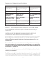
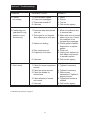
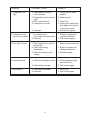
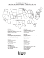
1
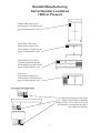
Randell Manufacturing, Inc.
OWNERS MANUAL
This manual provides information on installation, operating, maintenance,
troubleshooting & replacement parts for
PRODUCTION
FREEZERS
NOTIFY CARRIER OF DAMAGE AT ONCE.
It is the responsibility of the consignee to inspect the container upon receipt of same
and to determine the possibility of any damage, including concealed damage.
Randell suggests that if you are suspicious of damage to make a notation on the delivery receipt. It will be the responsibility of the consignee to file a claim with the carrier.
We recommend that you do so at once.
520 S. Coldwater Road Weidman, MI 48893-9683
Phone 1-800-621-8560 Fax 1-800-634-5369 www.randell.com
TABLE OF CONTENTS
Page 2 .......................................................................................................Congratulations
Page 3 ....................................................................................... Factory Correspondence
Page 4 ................................................................................................ Serial No. Location
Page 5 ...................................................................................... Randell Limited Warranty
Page 7 ...................................................................................................... Unit Installation
Page 9 ........................................................................................................ Unit Operation
Page 12 ................................................................................... Preventative Maintenance
Page 14 .................................................................................................. Troubleshooting
Congratulations on your recent purchase of Randell food service equipment, and
welcome to the growing family of satisfied Randell customers.
Our reputation for superior products is the result of consistent quality craftsmanship. From the earliest stages of product design, to successive steps in fabrication
and assembly, rigid standards of excellence are maintained by our staff of designers, engineers, and skilled employees.
Only the finest heavy-duty materials and parts are used in the production of
Randell brand equipment. This means that each unit, given the proper maintenance,
will provide years of trouble free service to its owner.
In addition, all Randell food service equipment is backed by one of the best
warranties in the food service industry and by our professional staff of service
technicians.
2
Retain this manual for future reference
Notice: Due to a continuous program of product improvement, Randell
Manufacturing reserves the right to make changes in design and
specifications without prior notice.
Notice: Please read the entire manual carefully before installation.
If certain recommended procedures are not followed, warranty
claims will be denied.
Model Number
Serial Number
Installation Date
Randell Manufacturing
Service and Parts
Hot line
1-800-621-8560
3
Randell Manufacturing
Serial Number Locations
1995 to Present
SERIES 2000 (Reach-Ins)
Serial number is located on the
upper left hand interior wall.
9300, 9400, 9800 Series
(Back-mount compressors)
Serial number is located on the
upper left hand interior wall.
20000 Series (Low Profile
Cooking Equipment Stands)
Serial number is located on the
upper left hand interior wall.
9200 Series
(Side-mount compressors)
Serial number is located on the
upper left hand interior wall.
9800A Series Drop-In Frost Tops.
9700A Series Drop-In Cold Pans.
Models 9550A, 9552A Drop-In Freezers
Serial number is located on the base of
the compressor housing.
4
Section I - Randell Manufacturing Limited Warranty
LABOR
Randell manufacturing warrants all repair labor charges on their equipment for the first
90 days. During the first 90 days work authorizations are not required for in warranty
repairs. However, repair times are limited to certain flex rate schedules and hours will be
deducted from service invoice if they extend past allotted times without prior approval
and a work authorization number. Warranties are effective from date of shipment, with a
30 day window to allow for shipment, installation and set-up.
Where equipment is shipped to any site other than final installation Randell will honor
the labor warranty for a period of 90 days following installation with proof of starting
date, up to a maximum of 9 months from date of purchase. Temperature adjustments
are not covered under warranty, due to the wide range of ambient conditions, Randell
assumes no liability for temperature adjustments. Travel time is limited to 1 hour each
direction or 2 hours per invoice. Any travel time exceeding 2 hours will be the responsibility of the customer.
PARTS
Randell Manufacturing warrants all component parts of new equipment to be free of
defects in material or “workmanship and that the equipment meets or exceeds reasonable industry standards of performance for a period of one year from the date of shipment from Randell.
Warranties are effective from date of shipment, with a 30 day window to allow for shipment, installation and set-up.
Where equipment is shipped to any site other than final installation Randell will honor
component parts warranty for a period of 12 months following installation with proof of
starting date, up to a maximum of 18 months from date of purchase.
Randell Manufacturing covers all shipping cost related to component part warranty sent
at regular rates within the continental United States (UPS, USPS). Cost incurred for red
label or any other specially arranged methods of shipping are the responsibility of the
customer.
EXTENSIONS
When the extended 1 year labor warranty is purchased, Randell agrees to pay regular
shop rates within regional hourly average for all warranted repairs occurring during the
first year of operation.
5
continued on page 6
Warranties are effective from the date of shipment, with a 30 day window to allow for
installation and set-up. Where equipment is shipped to any site other than final installation Randell will honor extended labor warranty for a period of 12 months following
installation with proof of start date, up to a maximum of 18 months from date of purchase.
When the optional 5 year extended compressor warranty is purchased, Randell will pay
for the replacement compressor only. During years 2-5 freight, labor, refrigerant, handling and all other charges are the responsibility of the customer. Randell will fulfill its
warranty obligations by using one of the 4 methods provided below:
1. Provide reimbursement to service company for the cost of locally obtained replacement compressor in exchange for the return of the defective compressor (sent freight
prepaid). Randell reserves the right to limit the amount of reimbursement allowed on
replacement compressors (customer should not pay service agent up front for compressor).
2. Provide repair at Randell by requiring that the defective unit be sent back freight
prepaid. Perform repair at the expense of Randell and ship the unit back to the person
sending it freight collect.
3. Furnish a replacement compressor freight collect in exchange for the return of the
defective compressor sent back freight prepaid.
4. Furnish complete condensing unit or a replacement package freight collect in exchange for the return of the defective compressor sent back freight prepaid. The decision on whether or not to send complete condensing units will be made by Randell’s
service technician.
Randell Manufacturing does not cover glass breakage on any unit produced once it has
been delivered in satisfactory condition. Also any glass breakage that occurs during
shipping needs to have a freight claim filed by the receiver with the shipping carrier.
Internal or concealed damage may fall under Randell’s responsibilities depending on
the circumstances surrounding each specific incident and are at the discretion of the
Randell service technician.
Randell Manufacturing does not cover gaskets under warranty. Gaskets are a maintenance type part that are subject to daily wear and tear and are the responsibility of the
owner of the equipment. Because of the unlimited number of customer related circumstances that can cause gasket failure, all gasket replacements are Considered nonwarranty.
NOTICE:
FOOD LOSS IS NOT COVERED UNDER WARRANTY
6
continued on page 7
Our export warranties will cover all non-electrical parts for a period of one year from the
date of shipment to be free of defects on material or workmanship. Electrical parts are
also covered if ordered and operated on 60 hertz. Electrical components, ordered and
operated on 50 hertz, are warranted for the first 90 days from shipment only. Service
labor is covered for first 90 days with authorization from factory prior to service.
Warranty is automatically initiated 60 days from ship date. Inbound costs on any factory
supplied items would be the responsibility of the customer. Adherence to recommended
equipment maintenance procedures, according to the owner’s manual provided with
each unit, is required for this warranty to remain in effect, and can have a substantial
effect on extending the service life of your equipment. Equipment abuse voids any
warranty. Extended warranties are not available for parts, labor or compressor on units
shipped outside the United States.
Section II - Installation
A. Receiving shipment
Upon arrival, examine the exterior of the shipping crate for signs of abuse. It is advisable that the shipping crate be partially removed, in order to examine the cabinet for any
possible concealed damages which might have occurred during shipment. If no damages are evident, replace the crate in order to protect the unit during local delivery. If the
unit is damaged, it should be noted on the delivery slip or bill of lading and signed to
that effect. A claim must be filed immediately against the carrier indicating extent and
estimated cost of damage incurred.
B. Locating your new freezer
The following conditions should be considered when selecting a location for your freezer:
1. Floor load - The floor on which the freezer will rest must be free of vibration and
suitably strong enough to support the combined weights of the unit plus the maximum
product load weight, it is generally acknowledged that a safe figure is 35 lbs. for each
net cubic foot of storage space (example, a 47 cubic foot cabinet could hold approximately 1645 lbs. of product 47 X 35 = 1645).
2. Clearance - There must be at least 3" of clearance on all sides of the unit.
Note: 2000 series Reach-in units require 6" of clearance above condensing units.
7
continued on page 8
3. Ventilation - The air cooled self-contained freezer requires a sufficient amount of cool
clean air. Avoid placing the freezer near heat generating equipment such as ovens
ranges heaters, fryers, steam kettles, etc. and out of direct sunlight. Avoid locating the
self-contained freezer in an unheated roam or where the room temperature may drop
below 55 degrees F. or above 90 degrees F.
C. Electrical Supply The wiring should be done by a qualified electrician in accordance with local electrical codes. A properly wired, and grounded outlet will assure
proper operation. Please consult the data plate attached to the compressor to ascertain
the correct electrical requirements. Supply voltage requirements are on the unit serial tag.
Note: It is important that a voltage reading be made at the compressor motor electrical
connections, while the freezer is in operation, to verify that the correct voltage required
by the compressor is being supplied. Low or high voltage can detrimentally affect the
refrigeration unit and thereby void its warranty.
Note: It is important that your unit have its own dedicated line. Condensing units are
designed to operate with a voltage fluctuation of plus or minus 10% of the voltage indicated on the unit data plate. Burn-out of a condensing unit due to exceeding voltage
limits will void the warranty.
D. Door and Drawer inspection Check door and drawers to insure that they are
sealing properly and that they are aligned (See dia. D. page 11).
Note: For units supplied with self-closing doors (See dia. C. page 11).
E. Installation checklist After the cabinet has been installed refer to the following
checklist prior to start-up:
1. Check all exposed refrigeration lines to ensure refrigeration lines are not
dented, kinked or rubbing.
2. Check condenser and evaporator fans for freedom to rotate freely without
striking any stationary members.
3. Cabinet must be properly leveled (see diagram A. page 10).
4. Refer to the front of this manual for serial number location. Please record this
information in your manual now. It will be necessary when ordering replace
ment parts or requesting warranty service.
5. Set cold controls to desired temperature for your individual application
(see diagram B. page 10).
8
continued on page 9
6. Drop in units must have 405 square inches of cross flow ventilation per side.
Equal to or greater than the louvers provided with each unit at the time of
purchase.
7. Check defrost setting for both number of defrost settings and time of defrost
activation.
Note: All motors are oiled and sealed.
Note: All self-contained models are shipped from the factory with the service valves
opened ready for operation.
Note: All non-programmable timers are scheduled for 6 defrost cycles (15 minute
durations) in a 24 hour period with activation times at the users discretion.
Section III - Operation
Allow your freezer to operate for approximately 2 hours before putting in food. This
allows the interior to cool down to the correct storage temperature. Randell has attempted to preset the cold control for an average interior temperature of 10 degrees at
the factory but due to varying ambient conditions including elevation, food product as
well as type of operation may alter this temperature. Additional adjustments can be
made (within limits) by turning the control dial up or down until the desired temperature
is reached. The temperature control dial is located either on the evaporator housing or
inside the compressor housing (see dia. B. page 10).
During normal operation, a freezer continuously circulates below freezing cabinet air
through the coil. Defrosting the coil requires a periodic supply of heat. This is accomplished by an automatic, time activated, temperature terminated, electric defrost system.
The programmable time clock is preset at the factory for four defrost cycles every 24
hours and the non-programmable type 6 cycles every 24 hours. However, this may be
easily changed to suit climatic conditions and usage, by adding or subtracting the number of cycles. To set up defrost cycles: open time clock cover and read the instructions
on the back of the cover, set defrost cycles as desired (see dia. E. page 11).
Adjustments to the defrost timer are not covered under warranty.
At the start of the defrost cycle, both the compressor and evaporator fans are off. The
electric defrost heater (attached to coil) and drain pan heater (attached to drain pan
below coil) are energized .
9
continued on page 10
When the defrost termination senses 58 degrees, the coil is fully defrosted and the
compressor operation is automatically resumed; defrost and drain pan heaters are
automatically de-energized and the compressor is activated. The coil fans are delayed
from starting at the termination of a defrost cycle. When the thermostat senses a coil
temperature of 35 degrees, drain line heater and fan operation is automatically
resumed. The freezer operation is now completely resumed.
During the defrost operation, heat is confined to the coil housing to prevent any significant rise in air temperature in the food zone, the fan delay action of the termination
thermostat is twofold. First to prevent blowing of warm air into the food storage area.
Second, to prevent any condensate retained on the defrosted coil, from being blown into
the food storage area.
Normal defrosting which is terminated by the temperature sensors will average 10 to 15
minutes. A fail safe provision to the defrost cycle with resulting damage to food storage
is provided by an override timer in the defrost clock. Setting the maximum duration of
the override timer at 25 minutes provides a fail safe system in the event that the defrost
terminator malfunctions.
Diagram A - Leveling of unit
The legs are equipped with bullet-type leveling bolts.
Turn bolts clockwise or counterclockwise until the
unit is level (both right to left and front to back). This
can be done by hand or with an open end wrench.
Clockwise for
colder operation
Diagram B - Temperature control adjustments
A control knob inside the cabinet- allows for adjustments. Turning the knob clockwise will result in
increased cooling. Keep the arrow on the knob
pointed within the green arc. Turning it clockwise
beyond the green can result in freeze-up, while
turning it counterclockwise beyond the green will
shut the compressor off.
For units equipped with a pressure control, adjust
temperature by turning adjustment screw clockwise to a lower number for colder temperature.
Turn adjustment screw counterclockwise to a
higher number for warmer temperature.
NOTE: NUMBERS ARE POUNDS OF
PRESSURE NOT DEGREES.
10
Diagram C - Resetting self-closing hinge
Loosen set screw, using a flat blade screwdriver turn bottom hinge (2) turns.
Turn clockwise on left hinged doors,
counterclockwise on right hand doors.
Hold hinge in wound position with
screwdriver and tighten set screw.
Set screw
Bottom door hinge
Bottom view of self-closing door
Lower Door
Adjustment
Diagram D - Door adjustment
The doors are mounted to the cabinet with
two screws on the upper hinge, and a hinge
pin on the bottom To adjust the door first
open it 90 degrees and remove the two
screws leaving the center adjusting screw
loose enough to reposition door. Once
repositioned, install all screws and tighten.
Diagram E - Defrosting Freezers
Manual defrost - to turn freezer into manual
defrost, with the style timer shown in figure “A”,
turn center shaft 90 degrees, with a flat tip
screwdriver, clockwise until a click is heard. If
your unit is equipped with a timer as illustrated
in figure “B” turn the reset knob until a pin in the
timer dial passes the reset knob.
Automatic defrost - Each Randell freezer
equipped with an automatic defrost timer, shuts
the compressor for a specified number of times
each day. When the unit is on defrost time,
water will drain from the evaporator through a
tube into the condensate evaporator pan at the
bottom or to a designated floor drain. The defrost timer cycle may be altered to a different
number of cycles if your unit is equipped with a
timer as shown in figure “B”.
Note: Both timers allow customer chosen
defrost times.
11
Diagram F - Doors with cam lift closures
To adjust or align cam lift doors, remove hinge cover and
loosen the three machine screws on door portion of hinge
plate, then pull hinge side of door in or out as necessary to
align door with cabinet front for proper gasket sealing (To
make door tighter move adjustment plate inward, to loosen
move adjustment plate out). Tighten hinges, replace hinge
cover and re-install door.
To align top or bottom corners of doors for level, loosen
screws on cabinet portion of hinge and align corners and
secure screws
Section IV - Preventative Maintenance
Randell strongly suggests a preventive maintenance program which would include the
following MONTHLY procedures:
1. Cleaning of all condenser coils. Condenser coils are a critical component in the life of
the compressor and must remain clean to assure proper air flow and heat transfer.
Failure to maintain this heat transfer will affect unit performance and eventually
destroy the compressor. Clean the condenser coils with coil cleaner (available at your
local appliance parts center) and/or a vacuum cleaner and brush.
Note: Brush coil in direction of fins, normally vertically
2. Clean all fan blades, both on the condensing unit and evaporator assembly.
3. Lubricate fan motor shafts, door hinges and drawer bearings. Lubricate fan motor
shafts with 3 in 1 oil and drawer bearings with white lithium grease.
4. Clean and disinfect drain lines and evaporator pan with a solution of warm water and
bleach.
5. Clean all gaskets on a weekly if not daily basis with a solution of warm water and a
mild detergent to extend gasket life.
NOTE:
DO NOT USE SHARP UTENSILS
12
continued on page 13
Recommended cleaners for specific situations
JOB
CLEANING AGENT
COMMENTS
Routine cleaning
Soap, ammonia, detergent
Medallion
Apply with a cloth or
sponge
Fingerprints and smears
Arcal 20, Lac-O-Nu, Ecoshine
Provides a barrier film
Stubborn stains and
discoloration
Cameo, Talc, Zud,
First Impression
Rub in the direction of the
polish lines.
Grease and fatty acids,
blood, burnt-on foods
Easy-off, De-grease It,
Oven Aid
Excellent removal on all
finishes
Grease and oil
Any good commercial detergent Apply with a sponge or
cloth
Restoration/Passivation
Benefit, Super Sheen
Reference:
Nickel Development Institute, DiverseyLeve, Savin, Ecolab, NAFEM
Do not use steel pads, wire brushes, scrapers or chloride cleaners to clean your
stainless steel.
CAUTION: DO NOT USE ABRASIVE CLEANING SOLVENTS, NEVER USE
HYDROCHLORIC ACID (MURIATIC ACID) ON STAINLESS STEEL.
Proper maintenance of equipment is the ultimate necessity in preventing costly repairs.
By evaluating each unit on a regular schedule you can often catch and repair minor
problems before they completely disable the unit and become burdensome on your
entire operation.
For more information on preventive maintenance consult your local service company.
Most repair companies offer this service at very reasonable rates to allow you the time
you need to run your business along with the peace of mind that all your equipment will
last throughout its expected life.
These services often offer guarantees as well as the flexibility in scheduling of maintenance for your convenience.
Randell believes strongly in the products it manufactures and backs those products with
one of the best warranties in the industry. We believe with the proper maintenance and
use you will realize a profitable return on your investment and years of satisfied service.
13
Section V Troubleshooting
PROBLEM
POSSIBLE CAUSE
REMEDY
A. Freezer
not running
1. Circuit breaker tripped
2. Power cord unplugged
3. Thermostat turned off
4. Unknown
1. Reset
2. Plug in
3. Turn on
4. Call service agency
B. Condensing unit
operates for long
periods or runs
continuously
1. Excessive heat load placed
into unit
2. Prolonged or too frequent
door openings or door ajar.
1. Allow unit sufficient time
to remove heat.
2. Make sure door is closed
when not in use. Correct
the condition of too
frequent door openings.
3. Check gasket condition.
Adjust door or replace
gasket.
4. Clean coil
5. Unplug unit, defrost coil
then adjust cold control
to warmer position
6. Call service agency
3. Gasket not sealing
4. Dirty condenser coil
5. Evaporator coil frozen
6. Unknown
C. Unit is noisy
1. Check for loose compressor
mounts
2. Check fan motor mounts
3. Check fan blades for
obstructions
4. Check all panels, louvers
and covers
5. Unknown
Troubleshooting continued on page 15
14
1. Tighten if necessary
2. Tighten if necessary
3. Remove any
obstructions. Tighten or
adjust shrouds.
4. Tighten and isolate as
needed
5. Call service agency
PROBLEM
POSSIBLE CAUSE
REMEDY
D. Temperature too
high
1. Check power cord and
circuit breaker
2. Temperature control set too
high
3. Dirty condenser coil
4. Evaporator coil froze
1. Plug in cord or reset
breaker
2. Adjust control
5. Unknown
3. Clean coil
4. Unplug unit, defrost coil
then adjust cold control
to warmer position
5. Call service agency
E. Compressor runs
but unit not cooling
1. Fan blades have
encountered an obstruction
2. Unknown
1. Check for obstruction
and free fan blade
2. Call service agency
F. Door will not close
1. Check opening for obvious
obstruction
2. Check self closing
mechanism
3. Check for loose or worn
hinges
1. Remove any obstruction
1. Check for blockage in drain
2. Check defrost system
1. Clean evaporator pan
and clear drain
2. Call service agent
1. Check defrost system
2. Unknown
1. De-ice coil
2. Call service agent
G. Unit leaks water
H. Ice build up
15
2. Adjust or replace self
closing mechanism
3. Replace hinges
Randell Manufacturing., Inc.
Authorized Parts Distributors
DEPOT #1
CASE PARTS CO.
877 Monterey Pass Road
Monterey Park, CA 91754 1-800-621-7884
(CA ONLY) 1-800-421-0271
DEPOT #5
COMMERCIAL PARTS
5310 E. 25th Street P.O. Box 18688
Indianapolis, IN 46218-0688
1-800-727-8710
DEPOT #2
REFRIGERATION HARDWARE SUPPLY
632 Foresight Circle
Grand Junction, CO 81505 1-800-423-2446
1-800-537-8300 (PAC. COAST)
DEPOT #6
HARRISON SUPPLY
Ridley Creek Plaza 5153 West Chester Pike
P.O. Box 596
Edgemont, PA 19028
1-800-521 -8444
DEPOT #3
STOVE PARTS SUPPLY
2120 Solona St.
Ft. Worth, TX 76117-0009
1-800-433-1804
DEPOT #4
GENERAL PARTS
11311 Hampshire Ave.
South Bloomington, MN 55438
1-800-279-9980
DEPOT #7
WHITESIDE PARTS
722 Brookhaven
Orlando, FL 32803
1-800-322-2678
✩
RANDELL MANUFACTURING., INC.
520 S. Coldwater Road
Weidman, Ml 48893
1-800-621 -8560