1
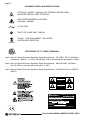
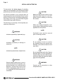
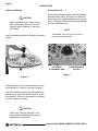
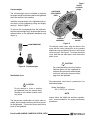
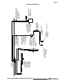
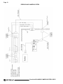
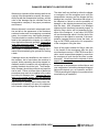
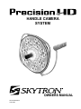
HANDLE CAMERA
SYSTEM
OWNERS MANUAL
TEC-B-0008 REV5
01/31/2013
Page 1
TABLE OF CONTENTS
TITLEPAGE
Equipment Labels...................................................................................................................................... 2
Camera Control Unit Safety Instructions................................................................................................... 3
Special User Attention............................................................................................................................... 4
Introduction................................................................................................................................................ 5
Installation................................................................................................................................................. 6
Camera Installation.............................................................................................................................. 6
Camera Removal................................................................................................................................. 6
Counterweight...................................................................................................................................... 7
Sterilizable Cover................................................................................................................................ 7
Operation................................................................................................................................................... 8
Camera Control Unit.................................................................................................................................. 9
Camera Specifications............................................................................................................................ 10
System Components................................................................................................................................11
Wiring Diagram........................................................................................................................................ 12
Damaged Shipment Claim Procedure..................................................................................................... 13
Revision History...................................................................................................................................... 15
Distributed by:
SKYTRON
5085 Corporate Exchange Blvd. S.E.
Grand Rapids, MI 49512 (616) 656-2900
www.skytron.us
Manufactured by:
DKK Dai-Ichi Shomei Co., LTD
32-26 Sakashita 1-Chome,
Itabashi- Ku, Tokyo 174-0043
JAPAN
Authorized Distributor Europe:
SKYTRON EUROPE BV
Floresstraat 52
8022 AD Zwolle
THE NETHERLANDS
Although current at the time of publication, SKYTRON’S policy of continuous development makes this
manual subject to change without notice.
PrecisionHD HANDLE CAMERA SYSTEM • REV5
Page 2
EQUIPMENT LABELS AND SPECIFICATIONS
EQUIPMENT LABELS AND SPECIFICATIONS
ATTENTION, CONSULT MANUAL FOR FURTHER INSTRUCTIONS.
INDICATES SPECIAL USER ATTENTION.
INDICATES DANGEROUS VOLTAGE
100-240V~, 50/60Hz
AC VOLTAGE
2A
TYPE B
EQUIPMENT
FUSE TYPE 2 AMP, 250V, TIMELAG
CLASS I, TYPE B EQUIPMENT- IPXO RATED.
CONTINUOUS OPERATION
CERTIFIED BY ETL TO THESE STANDARDS:
Audio, Video and Similar Electronic Apparatus: Safety Requirements - IEC 60065 : 2001 (7th Edition) +
Amendment 1 Edition 7.1, 01-Dec- 2005 (Edition 7:2001 consolidated with amendment 1:2005)
Audio, Video and Similar Electronic Apparatus: Safety Requirements - ANSI/UL 60065, 7th Edition: June 30, 2003 rev. through and including Dec 11, 2007
Audio, Video and Similar Electronic Apparatus: Safety Requirements - CAN/CSA-C22.2 No. 60065:03
(R2007)
CAUTION
RISK OF ELECTRIC SHOCK
DO NOT OPEN
AVERTISSEMENT
Risque de choc électrique
n'ouvrez pas
GRAND RAPIDS, MI · 616.656.2900
100-240V~,50/60Hz
100-240V~,50/60Hz
CAMERA CONTROLLER
ELECTRICAL RATING
INPUT 100-240V~
0.5A
PART NUMBER
B1-710-59
SERIAL NO.
50/60Hz
0000
Manufactured for SKYTRON by DAI-ICHI SHOMEI CO., LTD.TOKYO,JAPAN
PrecisionHD HANDLE CAMERA SYSTEM • REV5
Page 3
CAMERA CONTROL UNIT SAFETY INSTRUCTIONS
Read these instructions.
Keep these instructions.
Heed all warnings.
Follow all instructions.
Do not use this apparatus near water. This apparatus shall not be exposed to dripping or
splashing and no objects that contain water such as vases, shall be placed on the apparatus.
Clean only with dry cloth.
Do not block any ventilation openings. Install in accordance with the manufacurer’s instructions.
Do not install near any heat sources such as radiators, heat registers, stoves or other apparatus (including amplifiers) that produce heat.
Do not defeat the safety purpose of the polarized or grounding-type plug. A polarized plug has
two blades with one wider than the other. A grounding type plug has two blades and a third
grounding prong. The wide blade or the third prong are provided for your safety. If the provided
plug does not fit into your outlet, consult an electrician for replacement of the obsolete outlet.
Protect the power cord from being walked on or pinched particularly at plugs, convenience
receptacles, and the point where they exit from the apparatus.
Only use attachments/accessories specified by the manufacturer.
Unplug this apparatus during lightning storms or when unused for long periods of time.
Refer all servicing to qualified service personnel. Servicing is required when the apparatus has
been damaged in any way, such as power-supply cord or plug is damaged, liquid has been
spilled or objects have fallen into the apparatus, the apparatus has been exposed to rain or
moisture, does not operate normally or has been dropped. The Camera components do not
require scheduled maintenance.
The end of the useful life of the product is when the product can no longer be serviced to comply with IEC
standards as determined by a SKYTRON authorized service representative.
Ultimate disposal of this product
should be handled according to all
national laws and regulations.
PrecisionHD HANDLE CAMERA SYSTEM • REV5
Page 4
SPECIAL USER ATTENTION
To help assure the highest degree of operating
safety for user and patient, SKYTRON has provided
precautionary instructions throughout this manual.
As with the operation of any surgical light, all
hospital personnel should be aware that a certain
amount of care must be exercised to maintain patient safety and to keep your SKYTRON Surgical
Light performing at peak efficiency.
The following is a summary of the important precautionary instructions:
WARNING
Indicates a possibility of personal injury.
CAUTION
Indicates a possibility of damage to
equipment.
NOTE
Indicates important facts or helpful hints
CAUTION
Make sure Main Power Switch on the
light fixture Wall Control is in the OFF
position before installing or removing
the camera.
CAUTION
Make sure Camera Assembly is securely locked in lighthead before moving
lighthead into use position.
NOTE
Sterilizable cover must be removed
prior to removing camera.
CAUTION
Do not attempt to focus or position
the lighthead using the camera body.
Damage to the camera rotation motor
may result.
CAUTION
Do not accidentally push in the Camera
Release Button on the Lighthead Attachment Ring above the sterile handle,
as this will cause the camera to disengage from the lighthead.
WARNING
Always inspect product prior to use to
ensure safe and correct operation. any
product deemed to be malfunctioning
should be removed from service and
labeled innoperable. Refer all service
to at qualified SKYTRON service representative.
WARNING
Outputs are for connection to video
components only.
PrecisionHD HANDLE CAMERA SYSTEM • REV5
Page 5
INTRODUCTION
SKYTRON’S Precision HD Handle Camera System provides HD quality video to camera ready lightheads.
The Sony single chip camera provides quality levels that are comparable to many 3 chip systems. The
system design permits transport from room to room, wherever other Precision HD camera ready lightheads
are available. The camera control unit can be connected to any existing monitor. A convenient wall jack
is provided for camera control connection.
Figure 1. Precision HD Handle Camera in AUR7TV Lighthead
The Precision HD camera ready lighthead option
includes the Camera Ready Lighthead, a counterweight for use when the light is to be operated with
the camera removed, a sterilizable camera cover
that is used for a positioning/focus handle and a
connector face plate with a 65 foot cable that connects to the camera/light fixture.
The connector faceplate allows a quick connect or
disconnect point for the camera control unit. The
faceplate is mounted near where the camera con-
PrecisionHD HANDLE CAMERA SYSTEM • REV5
trol unit is to be located. It can be wall mounted,
installed within a cabinet such as a nurse documentation center or installed on a SKYTRON Skyboom
Equipment Carrier. Refer to page 10 for system
components.
The Precision HD Handle Camera System consists
of the camera, a camera control unit and two (2)
cables. The camera mounts in the center of the
lighthead and the sterilizable cover allows sterile
positioning and focus control for the lighthead.
Page 6
INSTALLATON
Camera Installation
Camera Removal
CAUTION
Make sure Main Power Switch on the
light fixture Wall Control is in the OFF
position before installing or removing
the camera.
Use the following procedure to install the camera
system.
To remove the camera assembly from the lighthead,
hold the camera firmly, and press the camera release button on the lighthead attachment ring (figure 3). Carefully pull the camera assembly straight
out of the attachment ring.
NOTE
Sterilizable cover must be removed
prior to removing camera.
LIGHTHEAD
ATTACHMENT RING
CAMERA RELEASE
BUTTON
Figure 3.
Figure 2.
Move lighthead to the full down position, and turn
the lighthead so it faces up as shown in figure 2.
Insert the Camera Assembly into the lighthead attachment ring. Push and twist the camera to lock
it into position. Pull out on the camera to verify that
it is fully locked into position.
`
CAUTION
Make sure Camera Assembly is securely locked in lighthead before moving
lighthead into use position.
PrecisionHD HANDLE CAMERA SYSTEM • REV5
Page 7
Counterweight
The counterweight must be installed to maintain
the proper weight required to balance the lighthead
when the camera is not installed.
COVER
LOCKING
PINS
LIGHTHEAD
ATTACHMENT
RING
Install the counterweight in the lighthead and ensure that it is fully engaged by pulling and slightly
turning it. Refer to figure 4.
To remove the counterweight from the lighthead,
hold the counterweight firmly, and press the camera
release button on the lighthead attachment ring
(figure 3).
STERILIZABLE
COVER
CAMERA
ASSEMBLY
COUNTERWEIGHT
Figure 5.
To install the sterile cover, align the holes in the
cover with the cover locking pins on the camera
attachment ring and slide the cover on until it locks
on the two pins. See figure 5. To remove the sterile
cover, push the two white pins in and remove the
sterile cover.
CAUTION
Figure 4. Counterweight
Sterilizable Cover
`
CAUTION
Do not attempt to focus or position
the lighthead using the camera body.
Damage to the camera rotation motor
may result.
The camera has a sterilizable cover that, when installed, allows sterile positioning and focus control
for the lighthead. There is also a non-sterile focus
knob on the lighthead.
PrecisionHD HANDLE CAMERA SYSTEM • REV5
Do not accidentally push in the Camera
Release Button on the Lighthead Attachment Ring above the sterile handle,
as this will cause the camera to disengage from the lighthead.
Recommended sterilization parameters for
sterilizable handle:
Steam Sterilization:
132°C (270°F) for 4 minutes
NOTE
Always follow the AAMI and sterilizer manufacturer recommendations for proper sterilization
procedures.
Page 8
Operation
Camera Control Unit Configuration
All parts of the camera system are suitable for use
within the patient area.
1. Attach the Cable from the connector on the
faceplate to the camera control unit (CCU). See
figure 7.
To ensure patient safety, do not touch any component of the system and the patient simultaneously.
Turn main power switch on at the Wall Control.
Adjust the intensity control.
The focus of the bulbs within the lighthead can be
adjusted by rotating the sterilizable cover or the
side focus knob. See figure 6.
9 PIN
CONNECTOR
Figure 7. Camera Control Connector
Faceplate
SIDE FOCUS
KNOB
WARNING
Outputs are for connection to video
components only.
2. Connect the video out cable (DVI, RGB, Component) from the camera control unit to the monitor
or video imput.
3. Connect the power cord to the CCU and plug into
120 VAC outlet. See figure 8. This power cord is
considered the main disconnect device and should
remain accessible at all times.
Figure 6.
To achieve optimal performance, install camera
control unit on a flat surface that is easily accessable by the operator with a minimum clearance of
2” on sides. Do not block vents.
RGB
DVI
OUTPUT OUTPUT
Y / Pb /
Pr
Y / Pb / Pr
INPUT
100-240V~
100-240V~,50/60Hz
100-240V~,50/60Hz
2AMP 100-240V~ INPUT
FUSES POWER CORD
CONNECTOR
PrecisionHD HANDLE CAMERA SYSTEM • REV5
Page 9
Camera Control Unit
The Camera Control Unit provides controls for
camera rotation, manual or automatic adjustment of
Iris (Aperture), Zoom, Focus and One Push White
Balance. Refer to figure 9 for control locations.
MAIN
POW-
WB
ZOOM
D
UP
CAMERA FOCUS
IRIS
ROTATION
AE
DOWN
ONE
PUSH
WB
Figure 9. Camera Control Unit, front view
ZOOM - controls the image size. To make the
subject larger, press the
button. To make the
subject smaller, press the
button.
AE AUTO - allows automatic control of both IRIS
and BRIGHT functions.
BRIGHT - adjusts both the gain and iris using an
internal algorithm according to a brightness level
freely set by the user. Exposure is controlled by
gain when dark, and by iris when bright.
IRIS (Aperture) - controls the video signal brightness by opening or closing the iris of the camera
to allow more or less light to enter the camera.
When Main Power switch is turned ON the Iris
control is set to automatic. To operate the Iris control manually, press the AE AUTO button. The “F”
stop setting will display on the monitor when in the
manual mode. Press the UP button to increase the
brightness. Press the DOWN button to decrease
the brightness. Press the AE AUTO button again
to activate the automatic function.
Description of Controls
UP / DOWN - used with IRIS and BRIGHT options.
MAIN POWER Switch - supplies power to the
camera and control unit. Switch illuminates (green)
when power is ON.
D ZOOM - controls digital zoom function. When
activated, extends zoom ratio from 10X to 40X.
CAMERA ROTATION - allows clockwise and
counterclockwise rotation of the camera. Press the
button for clockwise rotation. Press the
for
counterclockwise rotation.
FOCUS - controls the focus of the camera lens.
When Main Power switch is turned ON the Focus
control is set to automatic. To operate the Focus
control manually, press the AUTO button. The
Focus symbol will display on the monitor when in
the manual mode. Press the
or
button as
required to obtain proper focus. Pressing the
button sets the focus in the telephoto range. Pressing the
button sets the focus in the wide angle
range. Press the AUTO button again to activate
the automatic function.
PrecisionHD HANDLE CAMERA SYSTEM • REV5
DISPLAY - displays the current iris, zoom and focus
settings on the monitor.
FREEZE - press to capture present view “snapshot”. Press again to resume normal operation.
ONE PUSH WHITE BALANCE - press to white
balance picture.
Page 10
The Handle Camera system consists of a Lighthead handle mounted, super compact color HD camera
with a 120X zoom (10X Optical, 12X Digital) with a high speed, auto focus lens and flexible outputs for
video conferencing, broadcasting and point-of-view (POV) applications.v
SPECIFICATIONS:
Image Sensor
1/3-type CMOS
IrisAutomatic/Manual
Video Output
HD Analog Component:
Y/Pb/Pr, RGB.HD Digital Component: DVI
Min. Sensitivity
12 Lux (typical)
(F1.8, 50 IRE)
S/N Ratio
More than 50dB
White Balance
Auto, One Push
Picture Elements Approximately 2,000,000 pixels
Resolution
1080i (1920 X 1080) Analog
1080p (1920 X 1080) Digital
Lens
10X Optical Zoom f=5.1mm to 51.0mm (tele) F1.8 to F2.9
Zoom Ratio
10X-120X (Optical, 12X Digital)
Angle of View (H) 50 degrees (wide) to 5.4 degrees (tele)
Min. Object Distance 10mm (wide) to 800mm (tele)
FocusAutomatic/Manual
Camera RotationClockwise/Counterclock
wise 360 degrees
AE Control
Auto, Manual, Shutter Priority, Iris Priority,
Bright, Spot AE
Outside Dimensions 12.7”w x 3.5”h x 7.5”d (320mm x 89mm
x 191mm)
Weight
8 lbs. (3.6 kg)
PrecisionHD HANDLE CAMERA SYSTEM • REV5
CAMERA
B1-710-56
COUNTERWEIGHT
B1-710-66
STERILIZABLE
CAMERA COVER
B1-710-57
FIXTURE
JUNCTION BOX
PrecisionHD HANDLE CAMERA SYSTEM • REV5
POWER CORD FOR
CAMERA CONTROL UNIT
B9-211-04
VIDEO “OUT”
(COAXIAL CABLE (3) CONNECTOR)
B1-710-04
CAMERA CONTROL UNIT
B1-710-59
COAXIAL CABLE
(4) CONNECTOR
B1-710-03
WALL CONTROL
(SKYTRON SUPPLIED)
TO BE MOUNTED NEAR
ENTRANCE DOOR OR
AT N.D.C.
CAMERA CONTROL
JUNCTION BOX 2” X 4”
(SUPPLIED BY OTHERS)
TYPICAL LOCATION:
• NURSE DOCUMENTATION CENTER
• CABINET
• SHELF
65’ CAMERA CONTROL
CABLE W/FACEPLATE
& CONNECTOR
(SKYTRON SUPPLIED)
B1-710-02
1” METAL CONDUIT
FOR OPTIONAL CAMERA
SYSTEM CONTROL
(SUPPLIED BY OTHERS)
3/4” METAL CONDUIT
120VAC, 15A
INPUT DEDICATED
3/4” METAL CONDUIT 12AWG,
3 WIRES PER LIGHTHEAD
RED, GREEN, WHITE
30VDC OUTPUT
Page 11
SYSTEM COMPONENTS
Page 12
PRECISION HD CAMERA SYSTEM
PrecisionHD HANDLE CAMERA SYSTEM • REV5
Page 13
DAMAGED SHIPMENT CLAIM PROCEDURE
Whenever a shipment suffers damage while in the
custody of the transportation company, the responsibility lies with the transportation company, and the
value of the damages can be collected from the
transportation company if the proper procedures
are followed.
When a shipment is received in a damaged condition and due to the appearance of the containers
such as a broken crate, torn wrapping, or smashed
carton, the contents may have been damaged.
That fact should be noted on the Bill of Lading offered by the transportation company. An example
of an applicable statement would be; “Received in
good order except as noted” or “Crate damaged,
possibility of concealed damage.” The addition of
these types of statements on the shipping documents will automatically give grounds for starting
a claim.
If damage cannot be identified on the exterior of
the container, but is found when the container is
opened, further unpacking should be stopped immediately and the container with all wrapping or
packing materials should be held. The transportation company should be notified so an inspector
can be sent. Failure to follow either of these two
procedures may result in an inability to file a claim
and collect for damage done. Returning the container to the sender without such an inspection
may prevent filing a claim, because it will divide the
responsibility for damage and in many cases the
transportation company will return the shipment
to the sender without charge after the inspection.
PrecisionHD HANDLE CAMERA SYSTEM • REV5
The claim itself may be filed by either the shipper
or consignee, but the consignee must notify the
transportation company and the shipper that the
damage has occurred. Remember that refusal of
the shipment or failure to note the possibility of
damage on the shipping documents may jeopardize the claim. Also, acceptance of a damaged
shipment which has been processed properly to
allow for filing a claim, will not jeopardize the position of the consignee. In any case, SKYTRON
will see that damage which is not the fault of the
consignee or his agents is corrected, if the transportation company does not honor the claim, as
long as SKYTRON receives the full cooperation
of the consignee in filing the claim.
Some of the papers needed for filing a claim are
in the hands of the consingnee after the shipment has been received. If SKYTRON must file a
claim, we will request these papers by name from
the consignee at such time as the claim is under
discussion. We will require the originals of these
papers and not copies.
Knowledge of the procedures outlined above and
your cooperation in submitting damaged shipment
claims will help both you, our customer, and SKYTRON by assuring the integrity of our products from
manufacturing to installation.
Page 14
PrecisionHD HANDLE CAMERA SYSTEM • REV5
REVISION HISTORY
Date
01/31/2013
Revision
5
Author
Bill Brady
Page 15
Summary of Changes
Updated sterilization parameters and note on page
7.
PrecisionHD HANDLE CAMERA SYSTEM • REV5
5085 Corporate Exchange Blvd. S.E.
Grand Rapids, MI 49512 • 1.616.656.2900 • FAX 1.616.656.2906