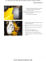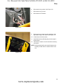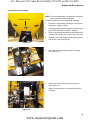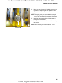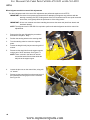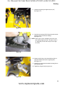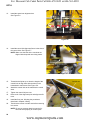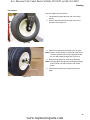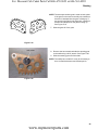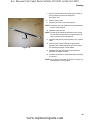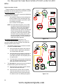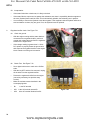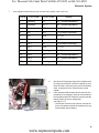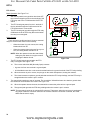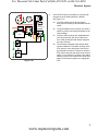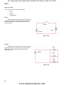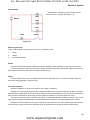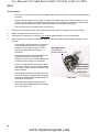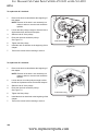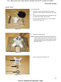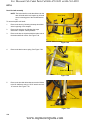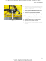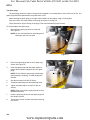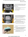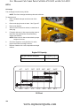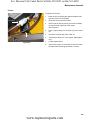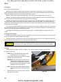
1
For Discount Cub Cadet Parts Call 606-678-9623 or 606-561-4983 Professional Shop Manual RZT-S NOTE: These materials are for use by trained technicians who are experienced in the service and repair of outdoor power equipment of the kind described in this publication, and are not intended for use by untrained or inexperienced individuals. These materials are intended to provide supplemental information to assist the trained technician. Untrained or inexperienced individuals should seek the assistance of an experienced and trained professional. Read, understand, and follow all instructions and use common sense when working on power equipment. This includes the contents of the product’s Operators Manual, supplied with the equipment. No liability can be accepted for any inaccuracies or omission in this publication, although care has been taken to make it as complete and accurate as possible at the time of publication. However, due to the variety of outdoor power equipment and continuing product changes that occur over time, updates will be made to these instructions from time to time. Therefore, it may be necessary to obtain the latest materials before servicing or repairing a product. The company reserves the right to make changes at any time to this publication without prior notice and without incurring an obligation to make such changes to previously published versions. Instructions, photographs and illustrations used in this publication are for reference use only and may not depict actual model and component parts. © Copyright 2012 MTD Products Inc. All Rights Reserved MTD Products Inc. - Product Training and Education Department www.mymowerparts.com For Discount Cub Cadet Parts Call 606-678-9623 or 606-561-4983 www.mymowerparts.com For Discount Cub Cadet Parts Call 606-678-9623 or 606-561-4983 Table of Contents Chapter 1: Introduction Professional Shop Manual intent . . . . . . . . . . . . . . . . . . . . . . . . . . . . . . . . . . . 1 Fasteners . . . . . . . . . . . . . . . . . . . . . . . . . . . . . . . . . . . . . . . . . . . . . . . . . . . . . 1 Assembly . . . . . . . . . . . . . . . . . . . . . . . . . . . . . . . . . . . . . . . . . . . . . . . . . . . . . 3 Description of the RZT-S . . . . . . . . . . . . . . . . . . . . . . . . . . . . . . . . . . . . . . . . . 3 Model and Serial Numbers . . . . . . . . . . . . . . . . . . . . . . . . . . . . . . . . . . . . . . . 4 Chapter 2: Engine related parts Muffler . . . . . . . . . . . . . . . . . . . . . . . . . . . . . . . . . . . . . . . . . . . . . . . . . . . . . . . 5 Fuel tank removal/replacement . . . . . . . . . . . . . . . . . . . . . . . . . . . . . . . . . . . . 6 Fuel pick up tube . . . . . . . . . . . . . . . . . . . . . . . . . . . . . . . . . . . . . . . . . . . . . . . 8 Fuel Line . . . . . . . . . . . . . . . . . . . . . . . . . . . . . . . . . . . . . . . . . . . . . . . . . . . . . . 9 Evaporative (EVAP) emissions system . . . . . . . . . . . . . . . . . . . . . . . . . . . . . . 10 Roll over valve vent . . . . . . . . . . . . . . . . . . . . . . . . . . . . . . . . . . . . . . . . . . . . . 12 Control cable adjustment . . . . . . . . . . . . . . . . . . . . . . . . . . . . . . . . . . . . . . . . 14 Chapter 3: Body Floor pan . . . . . . . . . . . . . . . . . . . . . . . . . . . . . . . . . . . . . . . . . . . . . . . . . . . . . 15 Left fender . . . . . . . . . . . . . . . . . . . . . . . . . . . . . . . . . . . . . . . . . . . . . . . . . . . . 17 Right fender . . . . . . . . . . . . . . . . . . . . . . . . . . . . . . . . . . . . . . . . . . . . . . . . . . 18 Seat box assembly . . . . . . . . . . . . . . . . . . . . . . . . . . . . . . . . . . . . . . . . . . . . . 20 Chapter 4: Brake and Drive System Brake system description . . . . . . . . . . . . . . . . . . . . . . . . . . . . . . . . . . . . . . . . 23 Brake adjustment . . . . . . . . . . . . . . . . . . . . . . . . . . . . . . . . . . . . . . . . . . . . . . 24 Brake puck/rotor replacement . . . . . . . . . . . . . . . . . . . . . . . . . . . . . . . . . . . . . 25 Brake shaft Bushings . . . . . . . . . . . . . . . . . . . . . . . . . . . . . . . . . . . . . . . . . . . 28 Drive belt . . . . . . . . . . . . . . . . . . . . . . . . . . . . . . . . . . . . . . . . . . . . . . . . . . . . . 30 Drive belt adjustment . . . . . . . . . . . . . . . . . . . . . . . . . . . . . . . . . . . . . . . . . . . 32 Hydro neutral control adjustment . . . . . . . . . . . . . . . . . . . . . . . . . . . . . . . . . . 38 Control pedal shaft assembly . . . . . . . . . . . . . . . . . . . . . . . . . . . . . . . . . . . . . 41 Chapter 5: Steering Introduction . . . . . . . . . . . . . . . . . . . . . . . . . . . . . . . . . . . . . . . . . . . . . . . . . . . 47 Wheel alignment and drive control link adjustments . . . . . . . . . . . . . . . . . . . 48 Front wheels . . . . . . . . . . . . . . . . . . . . . . . . . . . . . . . . . . . . . . . . . . . . . . . . . . 51 Front yokes . . . . . . . . . . . . . . . . . . . . . . . . . . . . . . . . . . . . . . . . . . . . . . . . . . . 53 Removal of the steering gears . . . . . . . . . . . . . . . . . . . . . . . . . . . . . . . . . . . . 54 Drag links . . . . . . . . . . . . . . . . . . . . . . . . . . . . . . . . . . . . . . . . . . . . . . . . . . . . 58 I www.mymowerparts.com For Discount Cub Cadet Parts Call 606-678-9623 or 606-561-4983 Chapter 6: electrical system Introduction . . . . . . . . . . . . . . . . . . . . . . . . . . . . . . . . . . . . . . . . . . . . . . . . . . . 61 PTO Switch . . . . . . . . . . . . . . . . . . . . . . . . . . . . . . . . . . . . . . . . . . . . . . . . . . 63 Brake Switch . . . . . . . . . . . . . . . . . . . . . . . . . . . . . . . . . . . . . . . . . . . . . . . . . . 63 Reverse Safety Switch . . . . . . . . . . . . . . . . . . . . . . . . . . . . . . . . . . . . . . . . . . 64 Seat Safety Switch . . . . . . . . . . . . . . . . . . . . . . . . . . . . . . . . . . . . . . . . . . . . . 64 Starter solenoid . . . . . . . . . . . . . . . . . . . . . . . . . . . . . . . . . . . . . . . . . . . . . . . . 65 PTO Relay . . . . . . . . . . . . . . . . . . . . . . . . . . . . . . . . . . . . . . . . . . . . . . . . . . . 65 Start Circuit . . . . . . . . . . . . . . . . . . . . . . . . . . . . . . . . . . . . . . . . . . . . . . . . . . . 66 Run Circuit . . . . . . . . . . . . . . . . . . . . . . . . . . . . . . . . . . . . . . . . . . . . . . . . . . . 69 Engine shut-down circuits . . . . . . . . . . . . . . . . . . . . . . . . . . . . . . . . . . . . . . . . 70 Charging circuit . . . . . . . . . . . . . . . . . . . . . . . . . . . . . . . . . . . . . . . . . . . . . . . . 71 PTO Circuit . . . . . . . . . . . . . . . . . . . . . . . . . . . . . . . . . . . . . . . . . . . . . . . . . . . 76 Diagnostic Techniques . . . . . . . . . . . . . . . . . . . . . . . . . . . . . . . . . . . . . . . . . . 78 Electronics . . . . . . . . . . . . . . . . . . . . . . . . . . . . . . . . . . . . . . . . . . . . . . . . . . . 78 Electrical environment: AC Vs. DC . . . . . . . . . . . . . . . . . . . . . . . . . . . . . . . . . 79 Ohm’s Law . . . . . . . . . . . . . . . . . . . . . . . . . . . . . . . . . . . . . . . . . . . . . . . . . . . 80 Kirchhoff’s current law . . . . . . . . . . . . . . . . . . . . . . . . . . . . . . . . . . . . . . . . . . . 80 Kirchhoff’s voltage law . . . . . . . . . . . . . . . . . . . . . . . . . . . . . . . . . . . . . . . . . . 81 How the system is wired together . . . . . . . . . . . . . . . . . . . . . . . . . . . . . . . . . 81 Types of circuits . . . . . . . . . . . . . . . . . . . . . . . . . . . . . . . . . . . . . . . . . . . . . . . 82 Series . . . . . . . . . . . . . . . . . . . . . . . . . . . . . . . . . . . . . . . . . . . . . . . . . . . . . . . 82 Parallel . . . . . . . . . . . . . . . . . . . . . . . . . . . . . . . . . . . . . . . . . . . . . . . . . . . . . . 82 Series/parallel . . . . . . . . . . . . . . . . . . . . . . . . . . . . . . . . . . . . . . . . . . . . . . . . . 83 Shorts . . . . . . . . . . . . . . . . . . . . . . . . . . . . . . . . . . . . . . . . . . . . . . . . . . . . . . . 83 Opens . . . . . . . . . . . . . . . . . . . . . . . . . . . . . . . . . . . . . . . . . . . . . . . . . . . . . . 83 Increased resistance . . . . . . . . . . . . . . . . . . . . . . . . . . . . . . . . . . . . . . . . . . . 83 The Tools . . . . . . . . . . . . . . . . . . . . . . . . . . . . . . . . . . . . . . . . . . . . . . . . . . . . 84 Digital Multi-meter . . . . . . . . . . . . . . . . . . . . . . . . . . . . . . . . . . . . . . . . . . . . . . 85 Wiring diagram or schematic . . . . . . . . . . . . . . . . . . . . . . . . . . . . . . . . . . . . . 86 Fused jumper wires . . . . . . . . . . . . . . . . . . . . . . . . . . . . . . . . . . . . . . . . . . . . . 86 Test lights. . . . . . . . . . . . . . . . . . . . . . . . . . . . . . . . . . . . . . . . . . . . . . . . . . . . 86 Self-powered continuity lights . . . . . . . . . . . . . . . . . . . . . . . . . . . . . . . . . . . . . 86 Ammeters and specialized charging system testers . . . . . . . . . . . . . . . . . . . . 87 Batteries . . . . . . . . . . . . . . . . . . . . . . . . . . . . . . . . . . . . . . . . . . . . . . . . . . . . . 88 Charging the battery . . . . . . . . . . . . . . . . . . . . . . . . . . . . . . . . . . . . . . . . . . . 88 Checking battery condition . . . . . . . . . . . . . . . . . . . . . . . . . . . . . . . . . . . . . . . 89 Battery Testers . . . . . . . . . . . . . . . . . . . . . . . . . . . . . . . . . . . . . . . . . . . . . . . . 90 Adjustable load testers . . . . . . . . . . . . . . . . . . . . . . . . . . . . . . . . . . . . . . . . . . 90 Fixed load testers . . . . . . . . . . . . . . . . . . . . . . . . . . . . . . . . . . . . . . . . . . . . . . 91 Conductance testers . . . . . . . . . . . . . . . . . . . . . . . . . . . . . . . . . . . . . . . . . . . 91 Battery discharge test . . . . . . . . . . . . . . . . . . . . . . . . . . . . . . . . . . . . . . . . . . . 92 Storage of batteries . . . . . . . . . . . . . . . . . . . . . . . . . . . . . . . . . . . . . . . . . . . . 92 Electrical Troubleshooting . . . . . . . . . . . . . . . . . . . . . . . . . . . . . . . . . . . . . . . . 93 Voltage Drop Test . . . . . . . . . . . . . . . . . . . . . . . . . . . . . . . . . . . . . . . . . . . . . . 95 Testing switches . . . . . . . . . . . . . . . . . . . . . . . . . . . . . . . . . . . . . . . . . . . . . . . 98 II www.mymowerparts.com For Discount Cub Cadet Parts Call 606-678-9623 or 606-561-4983 Diodes . . . . . . . . . . . . . . . . . . . . . . . . . . . . . . . . . . . . . . . . . . . . . . . . . . . . . . 99 Relay . . . . . . . . . . . . . . . . . . . . . . . . . . . . . . . . . . . . . . . . . . . . . . . . . . . . . . . 101 Schematic . . . . . . . . . . . . . . . . . . . . . . . . . . . . . . . . . . . . . . . . . . . . . . . . . . . 102 Chapter 7: Decks and lift shaft Cutting decks . . . . . . . . . . . . . . . . . . . . . . . . . . . . . . . . . . . . . . . . . . . . . . . . 103 Cleaning the deck . . . . . . . . . . . . . . . . . . . . . . . . . . . . . . . . . . . . . . . . . . . . . 104 To clean the deck while it is removed . . . . . . . . . . . . . . . . . . . . . . . . . . . . . . 104 Blades . . . . . . . . . . . . . . . . . . . . . . . . . . . . . . . . . . . . . . . . . . . . . . . . . . . . . . 105 Deck belt . . . . . . . . . . . . . . . . . . . . . . . . . . . . . . . . . . . . . . . . . . . . . . . . . . . . 107 Idler pulleys . . . . . . . . . . . . . . . . . . . . . . . . . . . . . . . . . . . . . . . . . . . . . . . . . . 109 Spindle shafts . . . . . . . . . . . . . . . . . . . . . . . . . . . . . . . . . . . . . . . . . . . . . . . . 111 Spindle removal/installation . . . . . . . . . . . . . . . . . . . . . . . . . . . . . . . . . . . . . . 112 Spindle overhaul . . . . . . . . . . . . . . . . . . . . . . . . . . . . . . . . . . . . . . . . . . . . . . 113 Leveling the deck . . . . . . . . . . . . . . . . . . . . . . . . . . . . . . . . . . . . . . . . . . . . . 115 Front To Rear (pitch) Leveling . . . . . . . . . . . . . . . . . . . . . . . . . . . . . . . . . . . 116 Deck Gauge Wheel Adjustment . . . . . . . . . . . . . . . . . . . . . . . . . . . . . . . . . . 117 Deck lift shaft assembly . . . . . . . . . . . . . . . . . . . . . . . . . . . . . . . . . . . . . . . . 118 Chapter 8: Maintenance intervals Lubrication . . . . . . . . . . . . . . . . . . . . . . . . . . . . . . . . . . . . . . . . . . . . . . . . . . 121 Engine maintenance . . . . . . . . . . . . . . . . . . . . . . . . . . . . . . . . . . . . . . . . . . . 121 The spark plugs . . . . . . . . . . . . . . . . . . . . . . . . . . . . . . . . . . . . . . . . . . . . . . 122 Air filter . . . . . . . . . . . . . . . . . . . . . . . . . . . . . . . . . . . . . . . . . . . . . . . . . . . . . 123 Oil change . . . . . . . . . . . . . . . . . . . . . . . . . . . . . . . . . . . . . . . . . . . . . . . . . . . 124 Oil filter . . . . . . . . . . . . . . . . . . . . . . . . . . . . . . . . . . . . . . . . . . . . . . . . . . . . . 125 Fuel system . . . . . . . . . . . . . . . . . . . . . . . . . . . . . . . . . . . . . . . . . . . . . . . . . . 126 Servicing the fuel system . . . . . . . . . . . . . . . . . . . . . . . . . . . . . . . . . . . . . . . . 126 Fuel filter . . . . . . . . . . . . . . . . . . . . . . . . . . . . . . . . . . . . . . . . . . . . . . . . . . . . 126 Clean the engine . . . . . . . . . . . . . . . . . . . . . . . . . . . . . . . . . . . . . . . . . . . . . . 127 Transmissions . . . . . . . . . . . . . . . . . . . . . . . . . . . . . . . . . . . . . . . . . . . . . . . . 127 III www.mymowerparts.com For Discount Cub Cadet Parts Call 606-678-9623 or 606-561-4983 IV www.mymowerparts.com For Discount Cub Cadet Parts Call 606-678-9623 or 606-561-4983 Introduction CHAPTER 1: INTRODUCTION Professional Shop Manual intent This Manual is intended to provide service dealers with an introduction to the mechanical aspects of the RZT-S zero-turn mower. • Detailed service information about the engine will be provided by the engine manufacturer, in most cases. Disclaimer: The information contained in this manual is correct at the time of writing. Both the product and the information about the product are subject to change without notice. About the text format: NOTE: is used to point out information that is relevant to the procedure, but does not fit as a step in the procedure. • Bullet points: indicate sub-steps or points. ! CAUTION Caution is used to point out potential danger to the technician, operator, bystanders, or surrounding property. ! WARNING Warning indicates a potentially hazardous situation that, if not avoided, could result in death of serious injury. ! DANGER Danger indicates an imminently hazardous situation that, if not avoided, will result in death or serious injury. This signal word is to be limited to the most extreme situations. Disclaimer: This manual is intended for use by trained, professional technicians. • Common sense in operation and safety is assumed. • In no event shall MTD or Cub Cadet be liable for poor text interpretation or poor execution of the procedures described in the text. • If the person using this manual is uncomfortable with any procedures they encounter, they should seek the help of a qualified technician or Cub Cadet Technical Support. Fasteners • Most of the fasteners used on these mowers are sized in fractional inches. The engine and transmissions are metric. For this reason, wrench sizes are frequently identified in the text, and measurements are given in U.S. and metric scales. • If a fastener has a locking feature that has worn, replace the fastener or apply a small amount of releasable thread locking compound such as Loctite® 242 (blue). • Some fasteners like cotter pins are single-use items that are not to be reused. Other fasteners such as lock washers, retaining rings, and internal cotter pins (hairpin clips) may be reused if they do not show signs of wear or damage. This manual leaves that decision to the judgement of the technician. 1 www.mymowerparts.com For Discount Cub Cadet Parts Call 606-678-9623 or 606-561-4983 RZT-S • Be prepared in case of emergency: ! CAUTION Keep a fire extinguisher nearby Keep a first aid kit nearby Keep emergency contact numbers handy • Replace any missing or damaged safety labels on shop equipment. • Replace any missing or damaged safety labels on equipment being serviced. • Grooming and attire: ! WARNING Do not wear loose fitting clothing that may become entangled in equipment. Long hair should be secured to prevent entanglement in equipment. Jewelry is best removed. • Protective gear: includes, but is not limited to Clear eye protection ................................ while working around any machinery Protective gloves ..................................... where necessary Armored footwear .................................... when working around any machinery Hearing protection ................................... in noisy environments Chemically resistant gloves ..................... when working with chemicals or solvents Respirator ................................................ when working with chemical or solvents Appropriate tinted eye protection............. when cutting or welding Flame resistant headgear, jacket, chaps . when cutting or welding • Remember that some hazards have a cumulative effect. A single exposure may cause little or no harm, but continual or repeated exposure may cause very serious harm. • Clean spills and fix obviously dangerous conditions as soon as they are noticed. • Lift and support heavy objects safely and securely. • Be aware of your surroundings and potential hazards that are inherent to all power equipment. All the labels in the world cannot protect a technician from an instant of carelessness. ! CAUTION • ! DANGER Exhaust fumes from running engines contain carbon monoxide (CO). Carbon monoxide is a colorless odorless gas that is fatal if inhaled in sufficient quantity. Only run engines in well ventilated areas. If running engines indoors, use an exhaust evacuation system with adequate make-up air ventilated into the shop. 2 www.mymowerparts.com For Discount Cub Cadet Parts Call 606-678-9623 or 606-561-4983 Introduction Assembly Torque specifications may be noted in the part of the text that covers assembly, they may also be summarized in tables along with special instructions regarding locking or lubrication. Whichever method is more appropriate will be used. In many cases, both will be used so that the manual is handy as a quick-reference guide as well as a step-bystep procedure guide that does not require the user to hunt for information. The level of assembly instructions provided will be determined by the complexity of dis-assembly/reassembly, and by the potential for unsafe conditions to arise from mistakes made in assembly. Some instructions may refer to other parts of the manual for subsidiary procedures. This avoids repeating the same procedure two or three times in the manual. Description of the RZT-S The RZT-S combines a traditional RZT lap bar zero turn rider (ZTR) with Cub Cadet’s patented Syncro SteerTM technology. The magic of the system: variable ratio steering gears that turn the front wheels much further than conventional systems. The steering control is linked to the traction drive system control. The traction drive system synchronizes the steering angle of the front tires with the speed and direction of rotation of the rear tires. Figure 1.1 A true zero-turn maneuver is achieved when the operator turns the steering wheel far enough that the inside rear wheel spins in reverse just like a traditional lap-bar controlled ZTR. 3 www.mymowerparts.com For Discount Cub Cadet Parts Call 606-678-9623 or 606-561-4983 RZT-S Model and Serial Numbers The model and serial number tag can be found under the seat. See Figure 1.2. The serial number is located to the right of the model number as shown above. See Figure 1.2. Figure 1.2 The model number is 17WF2BDS055. The break down of what the number mean is as follows: 1 .............................................................................................. Residential machine ....7 .......................................................................................... Residential zero turn mower .......W. ..................................................................................... Returnable crate ...........F.................................................................................... Engine code .............2. ................................................................................ Frame .................B ............................................................................. Transmission (B = EZT, G = ZT2800) ....................D.......................................................................... Style series .........................S ..................................................................... Deck (S = 42”, T = 46”, P=50”) .............................056 ............................................................. Customer number The serial number is 1B142H20124. The serial number reads as follows: 1 .............................................................................................. Engineering level ..B ............................................................................................ Month of production (B = February) .....14 ....................................................................................... Day of the month .........2 ..................................................................................... Last digit of the year ...........H................................................................................... Plant it was built in (Martin, TN) ..............2 ................................................................................ Assembly line number .................0124 ....................................................................... Number of unit built 4 www.mymowerparts.com For Discount Cub Cadet Parts Call 606-678-9623 or 606-561-4983 Engine Related Parts CHAPTER 2: ENGINE RELATED PARTS This chapter will cover the engine accessories that are manufactured by Cub Cadet. IMPORTANT: The engine is supplied by Kohler. Refer to the Kohler manual for engine specific service information. Muffler Remove the muffler by following these steps: Bumper 1. Remove the four screws (two on each side) that hold the rear bumper in place using a 1/2” wrench. See Figure 2.1. 2. Slide the bumper out from between the frame, the fuel tank bracket on the right and utility bin bracket on the left. Screws NOTE: The muffler guard will come off with the bumper. Figure 2.1 3. Remove the two screws that hold each exhaust pipe to the cylinder head using a T-27 torx driver. See Figure 2.2. 4. Remove the muffler and exhaust pipes. exhaust screws NOTE: The exhaust pipes are welded to the muffler. The pipes and the muffler are serviced as one assembly. 5. Clean and remove all gasket material from the cylinder head (and the exhaust pipe if they are being reused). 6. Using new gaskets, install the muffler by following the previous steps in reverse order. Exhaust pipe NOTE: Tighten the exhaust screws to a torque of 150 in lbs (17Nm). Figure 2.2 NOTE: When installing the bumper, start all four screws before tightening them. Otherwise the bumper will bind and the holes will not line up. 7. Test drive the mower in a safe area before returning it to service. IMPORTANT: Do not put a mower with an exhaust leak back in service. 5 www.mymowerparts.com For Discount Cub Cadet Parts Call 606-678-9623 or 606-561-4983 RZT-S Fuel System Fuel tank removal/replacement Remove/replace the fuel tank by following these steps: Gasoline and its vapors are extremely flammable. Use common sense when working around the fuel system. ! CAUTION 1. Remove the left fender: 1a. Remove the two screws, indicated by the arrows in Figure 2.3, from the underside of the fender using a 3/8” wrench. NOTE: The left rear wheel was removed for a clear view of the screws. Figure 2.3 1b. Remove the two screws, indicated by the arrows in Figure 2.4, from the inboard side of the fender using a T-27 torx driver. Figure 2.4 6 www.mymowerparts.com For Discount Cub Cadet Parts Call 606-678-9623 or 606-561-4983 Engine Related Parts Screw 1c. Remove the screw from the front of the fender using a T-27 torx driver. See Figure 2.5. 1d. Unscrew the fuel cap. NOTE: The fuel cap is tethered to the fender. This is an EPA tier III requirement. 1e. Lift the fender off of the mower. Figure 2.5 Fuel line Vent hose Roll over valve 2. Clamp off the fuel line between the fuel tank and the fuel filter. See Figure 2.6. 3. Disconnect the fuel line from the fuel tank at the fuel filter. 4. Disconnect the fuel tank vent line from the roll over valve. 5. Lift the fuel tank off of the mower. 6. Drain the fuel into an approved container. 7. Install the fuel tank by reversing previous steps. 8. Test drive the mower in a safe area before returning it to service. Figure 2.6 7 www.mymowerparts.com For Discount Cub Cadet Parts Call 606-678-9623 or 606-561-4983 RZT-S Fuel pick up tube The fuel tank on the RZT-S mower has a fuel pick up tube. This is a rigid tube that runs from the bottom of the tank to the top of the tank were the fuel line attaches to it. NOTE: A loose or missing pick up tube will allow air into the fuel system and will reduce or prevent fuel follow from the fuel tank to the engine. To remove/replace the pick up tube: 1. Pick up tube Remove the left fender by following the procedures described in Chapter 3: Body. 2. Clamp off the fuel line between the fuel tank and the fuel filter. See Figure 2.7. 3. Disconnect the fuel line from the pick up tube. Fuel line Figure 2.7 4. Gently pry the pick up tube and grommet out of the fuel tank. See Figure 2.8. 5. Inspect the grommet. Grommet NOTE: If the grommet is cracked or damaged, replace as needed. Figure 2.8 8 www.mymowerparts.com For Discount Cub Cadet Parts Call 606-678-9623 or 606-561-4983 Engine Related Parts Fitting 6. Inspect the pick up tube. See Figure 2.9. NOTE: If the pick up tube is loose or missing, it must be replaced. 7. Install the grommet in the fuel tank. 8. Insert the pick up tube into the fuel tank, through the grommet. 9. Re-connect the fuel line. 10. Install the left fender. Grommet pick up tube 11. Test run the mower in a safe area before returning it to service. Figure 2.9 Fuel Line NBR intermediate layer NBR inner liner The fuel line used by Cub Cadet is GREENbarTM. This is a multi-layer fuel line that meets the current EPA guidelines. NOTE: This fuel line has a thin inner liner. If a tear forms in this inner liner, fuel can get between the liner and the hose. This will cause the liner to collapse, cutting off the fuel flow. NOTE: Replace the fuel line only with GREENbarTM 700 series fuel line. CSM Cover Reinforcement THV barrier layer Figure 2.10 Picture courtesy of Avon Automotive 9 www.mymowerparts.com For Discount Cub Cadet Parts Call 606-678-9623 or 606-561-4983 RZT-S Evaporative (EVAP) emissions system The EPA has enacted rules that regulate the amount of vapors an engine’s fuel system is allowed to vent to the atmosphere. The rules are know as tier III emissions guidelines. These rules apply to all engines built on or after 1/1/ 2012. Some of the requirements of tier III emissions include: • Tethered fuel caps. • Unvented fuel caps. • Low permeation (GREENbarTM) fuel line • Roll over valve vents The fuel tank has an unvented fuel cap. The fuel tank vents through the roll over valve. The vapors will flow through the vent hose (black hose with a red trace) to the engine. See Figure 2.11. Roll over valve %NGINE Fuel tank The EVAP system, from the fuel tank up to the engine connector, is a Cub Cadet system, meaning warranty and parts are handled by Cub Cadet. Fuel pick up tube 49 state fuel system The engine side of the system varies by engine manufacturer, but on most engines the vent hose will go to the air intake manifold. NOTE: Units sold in California will have a charcoal canister to further reduce the amount of emissions that escape from the fuel system. Fuel cap Figure 2.11 %NGINE The fuel tank will vent through the charcoal canister. The charcoal in the canister will act as a filter and remove some of the vapors that are venting out of the fuel tank. A second vent hose connects the canister to the engine. As the engine runs, the vacuum in the intake manifold will draw the vapors out of the charcoal, recharging it. See Figure 2.12. NOTE: A leak in the vent hose will allow dirt injection in the engine. This will not affect engine performance until the dirt ingestion has cause damage inside the engine. 6ENT #HARCOAL CANISTER California fuel system Figure 2.12 10 www.mymowerparts.com For Discount Cub Cadet Parts Call 606-678-9623 or 606-561-4983 Engine Related Parts Troubleshooting Symptom Engine starts, then dies Cause A blockage in the vent hose. The roll over valve is stuck closed. Engine runs rich Raw gasoline in the charcoal canister (if equipped). A blockage in the line between the charcoal canister (if equipped) and the intake manifold. Engine runs lean Wrong fuel cap installed. Leak in the vacuum lines. Gasoline vapor escaping from the engine The charcoal canister (if equipped) is saturated. A blockage in the line between the charcoal canister (if equipped) and the intake manifold. Wrong fuel cap installed. Leak in the vacuum lines. 11 www.mymowerparts.com For Discount Cub Cadet Parts Call 606-678-9623 or 606-561-4983 RZT-S Roll over valve vent To remove the roll over valve: 1. Remove the left fender by following the procedures described in Chapter 3: Body. 2. Disconnect the vent hose. See Figure 2.13. Vent hose NOTE: The vent hose will have a red trace. Red trace Figure 2.13 3. 4. Gently pry the roll over valve out of the fuel tank. See Figure 2.14. Roll over valve Inspect the rubber grommet, replace if damaged. To install the roll over valve: 1. With the grommet on the roll over valve, install the roll over valve by pressing it into the opening in the tank. 2. Install the vacuum line. 3. Install the left fender. 4. Test run the engine in a safe area before returning to service. Figure 2.14 12 www.mymowerparts.com For Discount Cub Cadet Parts Call 606-678-9623 or 606-561-4983 Engine Related Parts Testing the roll over valve The roll over valve vent has two functions. The first function is to vent the tank and the second function is to close off the vent if the tank is inverted. 15 in.Hg. Test the roll over valve by: 1. Remove the roll over valve by following the steps previously described in this section. 2. Connect a vacuum pump to the roll over valve. 3. Hold the roll over valve in an inverted position. 4. Apply a vacuum to the roll over valve. See Figure 2.15. NOTE: The roll over valve should hold 15 in.Hg. for 15 seconds. Figure 2.15 5. Zero reading With the vacuum still applied, turn the roll over valve over. See Figure 2.16. NOTE: The vacuum should be relieved. 6. If the results do not match what is listed above, replace the roll over valve. Figure 2.16 13 www.mymowerparts.com For Discount Cub Cadet Parts Call 606-678-9623 or 606-561-4983 RZT-S Control cable adjustment To adjust the control cable: 1. Move the throttle lever to the detent between the full throttle and the choke position. 2. Loosen the clamp that holds the control cable jacket in position. See Figure 2.17. 3. Slide the cable jacket until the speed control lever makes contact with the choke lever. 4. Tighten the control cable jacket. 5. Move the throttle lever to the choke position. 6. Verify that the choke is fully closed. 7. Test run the mower in a safe area before returning it to service. Choke lever Contact point Speed control lever Control cable clamp Figure 2.17 14 www.mymowerparts.com For Discount Cub Cadet Parts Call 606-678-9623 or 606-561-4983 Body CHAPTER 3: BODY Floor pan To remove/replace the floor pan: 1. Remove the steering wheel: 1a. Turn the steering wheel so that the wheels are pointing straight ahead. 1b. Gently pry the cover off of the steering wheel. 1c. Remove the screw and washer that secures the steering wheel to the steering shaft using a 1/2” wrench. See Figure 3.1. 1d. Lift the steering wheel off of the steering shaft. Screw Figure 3.1 2. Remove the brake pedal: See Figure 3.2. 2a. Remove the screw that secures the brake pedal to the pedal shaft bell crank using a 1/2” wrench. 2b. Unhook the brake pedal from the bell crank. Brake pedal Pedal shaft bell crank Figure 3.2 15 www.mymowerparts.com For Discount Cub Cadet Parts Call 606-678-9623 or 606-561-4983 Z-Force-S 3. Remove the reverse pedal using a pair of 7/16” wrenches. See Figure 3.3. Reverse pedal Figure 3.3 4. Remove the forward drive pedal: See Figure 3.4. 4a. 4b. Remove the screw that secures the drive pedal to the pedal shaft bell crank using a 1/2” wrench. Forward drive pedal Unhook the drive pedal from the bell crank. Figure 3.4 5. Remove the lower steering column cover by removing the two screws, indicated by the arrows in Figure 3.4, using a T-30 torx driver. 6. Remove the nine screws that hold the floor pan to the frame using a T-30 torx driver. 7. Lift the floor pan off of the mower. 8. Install the floor pan by reversing the previous steps. NOTE: Confirm that all safety and control features work correctly. Do Not return an unsafe mower to service. Figure 3.5 16 www.mymowerparts.com For Discount Cub Cadet Parts Call 606-678-9623 or 606-561-4983 Body Left fender To remove/replace the left fender: NOTE: The fuel tank is nested inside the left fender. Gasoline and its vapors are extremely flammable. Use common sense when working around the fuel system. ! CAUTION 1. Remove the two screws, indicated by the arrows in Figure 3.6, from the underside of the fender using a 3/8” wrench. NOTE: The left rear wheel was removed for a clear view of the screws. Figure 3.6 2. Remove the two screws, indicated by the arrows in Figure 3.7, from the inboard side of the fender using a T-27 torx driver. 3. Remove the screw from the front of the fender using a T-27 torx driver. See Figure 3.8. 4. Unscrew the fuel cap. Figure 3.7 Screw NOTE: The fuel cap is tethered to the fender. This is an EPA tier III requirement. Figure 3.8 5. Lift the fender off of the mower. 6. Install the fender by following the previous steps in reverse order. NOTE: Confirm that all safety and control features work correctly. Do Not return an unsafe mower to service. 17 www.mymowerparts.com For Discount Cub Cadet Parts Call 606-678-9623 or 606-561-4983 Z-Force-S Right fender To remove/replace the right fender: 1. Remove the yellow throttle lever using a #1 phillips screwdriver. See Figure 3.9. 2. Disconnect the throttle lever assembly from the right fender using a T-30 torx driver. See Figure 3.9. Figure 3.9 3. Remove the two screws, indicated by the arrows in Figure 3.10, from the inboard side of the fender using a T-27 torx driver. Figure 3.10 4. Remove the screw from the front of the fender using a T-27 torx driver. See Figure 3.11. 5. Remove the deck lift lever grip. Screw Figure 3.11 18 www.mymowerparts.com For Discount Cub Cadet Parts Call 606-678-9623 or 606-561-4983 Body Hour meter Key switch 6. Disconnect the key switch. See Figure 3.12. 7. Disconnect the hour meter. 8. Disconnect the PTO switch. 9. Remove the two screws from the underside of the right fender using a 3/8” wrench. See Figure 3.13. PTO switch Figure 3.12 10. Lift the fender off of the mower. 11. Install the fender by following the previous steps in reverse order. 12. Test drive the mower in a safe area before returning it to service. NOTE: Confirm that all safety and control features work correctly. Do Not return an unsafe mower to service. Figure 3.13 19 www.mymowerparts.com For Discount Cub Cadet Parts Call 606-678-9623 or 606-561-4983 Z-Force-S Seat box assembly To remove/replace the seat box assembly: 1. Remove the battery. 2. Remove the deck by following the procedures described in Chapter 7: Decks and Lift Shaft. 3. Remove the left fender by following the procedures described in the left fender section of this chapter. 4. Remove the right fender by following the procedures described in the right fender section of this chapter 5. Disconnect the harness from the seat switch. 6. Remove the two screws securing the seat frame to the seat box using a 1/2” wrench. See Figure 3.14. Harness Screws Figure 3.14 7. Remove both of the seat springs using a 1/2” wrench. See Figure 3.15. 8. Remove the seat box cover using a 1/2” wrench. Seat springs Figure 3.15 9. Remove the two screws that hold the deck lift indexing bracket to the seat box using a 1/2” wrench. See Figure 3.16. Screws Figure 3.16 20 www.mymowerparts.com For Discount Cub Cadet Parts Call 606-678-9623 or 606-561-4983 Body 10. Remove the four screws (two on each side), securing the seat box to the cross member using a 1/2” wrench. See Figure 3.17. Screws Figure 3.17 Cross member screw 11. Seat box screws Remove the four screws (two on each side), that hold the seat box to the frame using a 1/2” wrench. See Figure 3.18. 12. Remove the two screws (one on each side), that hold the cross member to the frame NOTE: The cross member can be left in place. Figure 3.18 13. Remove the three pan head screws indicated by the arrows in Figure 3.19, that hold the front of the seat box to the frame using a T-30 torx driver. 14. Fish the wiring harness out of the seat box. 15. Lift the seat box assembly off of the mower. 16. Install the seat box by reversing the previous steps. 17. Test drive the mower in a safe area before returning it to service. NOTE: Confirm that all safety and control features work correctly. Do Not return an unsafe mower to service. Figure 3.19 21 www.mymowerparts.com For Discount Cub Cadet Parts Call 606-678-9623 or 606-561-4983 Z-Force-S 22 www.mymowerparts.com For Discount Cub Cadet Parts Call 606-678-9623 or 606-561-4983 Brakes and Drive System CHAPTER 4: BRAKE AND DRIVE SYSTEM Brake system description The RZT-S uses twin EZT Hydro-Gear transmissions to drive the rear wheels. The hydraulic action of the transmissions will provide the braking for the mower while it is in motion. There is a friction brake on the transmission that is used as a parking brake. • There is a brake for each transmission. Brake pedal • They are activated by depressing the brake pedal. • Depressing the brake pedal will cause the control pedal shaft to rotate. When the shaft rotates, a bell crank attached to it will pull on the main brake control rod. See Figure 4.1. Main brake control rod Figure 4.1 Brake shaft • The main brake rod will pull on a bell crank attached to the brake shaft. This will cause the brake shaft to rotate. NOTE: The brake shaft is held captive on the deck lift shaft. It is serviced with the deck lift shaft. Refer to the deck lift shaft section of Chapter 7: Decks and Lift Shaft for removal/replacement procedures. Main brake control rod De-clutching rod Secondary brake rods Figure 4.2 • As the brake shaft rotates, the two bell cranks will pull the secondary brake rods. The secondary brake rods will pull on the brake caliper arm, pushing the brake pins into the caliper, applying the brakes. See Figure 4.2. • A brake link rod connects the right brake shaft bell crank to the drive belt idler pulley bracket. When the brakes are applied, this link rod pulls on the idler pulley bracket, de-clutching the drive belt. 23 www.mymowerparts.com For Discount Cub Cadet Parts Call 606-678-9623 or 606-561-4983 RZT-S Brake adjustment NOTE: When performing a brake adjustment, inspect the brake components for signs of wear or damage. 1. Block the front wheels. 2. Lift and safely support the rear of the mower. NOTE: Make sure the parking brake is released. 3. Remove the cotter pin locking the castle nut on the brake caliper. See Figure 4.3. 4. Back the castle nut off a few turns using a 9/16” wrench. Castellated nut NOTE: Even if the brakes are set to the correct clearance, inserting a feeler gauge between the rotor and the brake puck can be very difficult. Loosen the castle nut first, then insert the feeler gauge and tighten the nut to set the proper clearances Cotter pin Figure 4.3 5. Insert a 0.030” (0.8 mm) feeler gauge between the brake rotor and the outboard brake puck. See Figure 4.4. NOTE: The tolerance for the brake clearance is 0.020” - 0.040” (0.5 - 1.0mm). The 0.030 feeler gauge will set the clearance at the midpoint. 6. Tighten the nut until there is slight drag on the feeler gauge. NOTE: For even braking, both sides should be set to the same clearance. 0.030” feeler gauge 7. Install a new cotter pin. 8. Repeat same procedure on the other side. 9. Take the mower off of the jack stands. 10. Open the bypass valves and check the parking brake before returning the mower to service. 11. Figure 4.4 • With the brakes released, the mower should have only hydraulic drag when it is pushed. • With the brakes engaged, the wheels should slide before they rotate when the mower is pushed. Test drive the mower in a safe area before returning it to service. NOTE: Check all safety and control features. Do Not return an unsafe mower to service. 24 www.mymowerparts.com For Discount Cub Cadet Parts Call 606-678-9623 or 606-561-4983 Brakes and Drive System Brake puck/rotor replacement On Hydro-Gear transmissions, the brake pucks are wearing parts that will need to be serviced from time to time. If a mower is operated with the parking brake dragging, the pucks will wear out rapidly and the brake rotor will develop hot spots. If the mower is operated long enough, the rotor may have grinding marks on it with excessively worn pucks. ! CAUTION If the rotor shows hot spots or any other signs of damage, including warpage, it must be replaced. Failure to do so can result in the failure of the brakes NOTE: Dragging brakes can cause symptoms similar to a failing transmission. Dragging brakes will also accelerate wear on the transmission. The brake pucks and the rotors are serviced at the same time. To service the brake pucks: Secondary brake rod 1. Lift and safely support the rear of the mower. 2. Make sure the parking brake is released. 3. Disconnect the secondary brake rod from the brake shaft bell crank by removing the bowtie clip. See Figure 4.5. 4. Slide the brake rod, spring and washer out of the brake cam arm. 5. Loosen the rear mounting bolt. See Figure 4.6. Figure 4.5 Remove this bolt Loosen this bolt Figure 4.6 25 www.mymowerparts.com For Discount Cub Cadet Parts Call 606-678-9623 or 606-561-4983 RZT-S 6. Remove the front mounting bolt, allowing the caliper to swing down. See Figure 4.7. 7. The outboard brake puck should fall out when the brake caliper swings down. If it did not, it can be removed now. Caliper Figure 4.7 8. Slide the brake rotor off to reach the inboard brake puck. See Figure 4.8. 9. Remove the caliper for inspection when servicing the brake pucks. To do this, remove the rear bolt loosened in step 4. Inboard brake puck Figure 4.8 10. 11. With the caliper on a work bench, remove the brake puck, backing plate and the two brake pins. See Figure 4.9. Brake caliper Check for free movement of the brake pins. A dry lubricant can be used on the brake pins sparingly. Brake pins ! CAUTION Never put grease or anti-seize on brake pins. It can migrate to the brake pucks, preventing the braking action Backing plate of the pucks. Brake puck 12. Slide the brake pins into the caliper. 13. Place the backing plate in the caliper. Figure 4.9 26 www.mymowerparts.com For Discount Cub Cadet Parts Call 606-678-9623 or 606-561-4983 Brakes and Drive System 14. Place a new puck into the caliper. See Figure 4.10. NOTE: A piece of scotch tape may be used to hold the new brake pucks in place for assembly. The tape will grind away when the brakes are applied. 15. Place a new brake puck into the recess in the transmission. Use a piece of scotch tape to hold it in place. 16. Slide the brake rotor in place, shoulder out. Puck held in place with tape Figure 4.10 17. Mount the brake caliper to the transmission. Apply a small amount of releasable thread locking compound such as Loctite® 242 (blue) to the mounting bolts and tighten to a torque of 80 - 120 in-lbs (9 - 13.5Nm). 18. Slide the brake rod, spring and washer into the brake cam arm. 19. Connect the secondary brake rod to the brake shaft bell crank and install the bowtie clip. 20. Adjust the brakes as described in the previous section of this chapter. 21. Repeat steps 4-19 on the other side. 22. When both sides are completed, take the mower off of the jack stands. 23. Open the by-pass valves and check the parking brake before returning the mower to service. • With the brakes released, the mower should have only hydraulic drag when it is pushed. • With the brakes engaged, the wheels should slide before they rotate when the mower is pushed. 24. Test drive the mower in a safe area before returning it to service. NOTE: Check all safety and control features. Do Not return an unsafe mower to service. 27 www.mymowerparts.com For Discount Cub Cadet Parts Call 606-678-9623 or 606-561-4983 RZT-S Brake shaft Bushings NOTE: The brake shaft is captive on the deck lift shaft. It is serviced with the deck lift shaft. Refer to the deck lift shaft section of Chapter 7: Decks and Lift Shaft for removal/replacement procedures. To replace the brake shaft bushings: 1. Remove the battery. 2. Remove the deck by following the procedures described in Chapter 7: Decks and Lift Shaft. 3. Remove the left fender by following the procedures described in Chapter 3: Body. 4. Remove the right fender by following the procedures described in Chapter 3: Body 5. Disconnect the harness from the seat switch. 6. Remove the two screws securing the seat frame to the seat box using a 1/2” wrench. See Figure 4.11. Harness Screws Figure 4.11 7. Remove both of the seat springs using a 1/2” wrench. See Figure 4.12. 8. Remove the seat box cover using a 1/2” wrench. Seat springs Figure 4.12 28 www.mymowerparts.com For Discount Cub Cadet Parts Call 606-678-9623 or 606-561-4983 Brakes and Drive System Brake shaft 9. Remove the split spacer from the right side of the deck lift shaft. See Figure 4.13. Split spacer Deck lift shaft Figure 4.13 10. Slide the right split bushing out of the brake shaft until it is full exposed. See Figure 4.14. Split bushing NOTE: Sliding the brake shaft to the left can help slide the bushing out of the brake shaft. 11. Remove the split bushing. 12. Install a new bushing. 13. Slide the brake shaft to the right enough to allow the left split bushing to be fully exposed Figure 4.14 14. Remove the bushing. 15. Install a new bushing. 16. Slide the brake shaft to the left enough to allow the split spacer to be installed. Split bushing 17. Install the split spacer. 18. Put the mower back together by reversing steps 1 - 8. 19. Test run the mower in a safe area before returning it to service. NOTE: Check all safety and control features. Do Not return an unsafe mower to service. Figure 4.15 29 www.mymowerparts.com For Discount Cub Cadet Parts Call 606-678-9623 or 606-561-4983 RZT-S Drive belt To remove/replace the drive belt: NOTE: If a drive belt fails prematurely, find and correct the cause of the failure. 1. Remove the deck as described in Chapter 7: Cutting Decks and Lift Shaft. 2. Lift and safely support the rear of the mower. 3. Remove the battery. See Figure 4.16. Battery Figure 4.16 4. Remove the nuts that hold the right belt guard to the frame using a 7/16” wrench. See Figure 4.17. 5. Remove the right belt guard. Nuts Figure 4.17 6. Remove the nuts that hold the left belt guard to the frame using a 7/16” wrench. NOTE: The front nut on the left belt guide will be inside the seat box, under the harness. 7. Remove the left belt guard. Nuts Figure 4.18 30 www.mymowerparts.com For Discount Cub Cadet Parts Call 606-678-9623 or 606-561-4983 Brakes and Drive System PTO Harness Belt guard 8. Remove the rear belt guard using a 3/8” wrench. See Figure 4.19. 9. Disconnect the harness from the PTO clutch Figure 4.19 10. Disconnect the brake de-clutching rod from the idler pulley bracket. See Figure 4.20. 11. Remove the idler pulley tensioning spring. 12. Loosen the bolt the idler pulley spins on enough to allow the belt to slip between the pulley and the belt guide. See Figure 4.21. Brake de-clutching rod Figure 4.20 13. The belt can now be snaked out of the mower. Spring Cub Cadet belts are designed to fit our equipment and are not standard lengths. Use of a non-OEM belt may prevent the de-clutching mechanism from working properly when the brakes are applied. ! CAUTION idler pulley 14. Install the belt by reversing the above steps. 15. Test drive the mower before returning to service. Figure 4.21 NOTE: Check all safety and control features. Do Not return an unsafe mower to service. 31 www.mymowerparts.com For Discount Cub Cadet Parts Call 606-678-9623 or 606-561-4983 RZT-S Drive belt adjustment The drive belt is tensioned by a spring loaded idler pulley. When the brakes are applied, the drive belt is declutched. An adjustable linkage connects the tensioning pulley to the brake shaft. A brake link that is out of adjustment will prevent the moveable idler from correctly tensioning and de-tensioning the belt. As the belt wears, the moveable idler needs to push the belt in further to keep proper belt tension. To do this, the ferrule at the end of the brake link needs to be at the rear of the slot in the idler pulley bracket. To adjust this brake link: NOTE: The brake link is properly adjusted when the belt is fully de-clutched as the brake is applied and fully tensioned when the brake is released. NOTE: The belt must be on when performing this adjustment. 1. Release the parking brake. 2. Remove the deck as described in Chapter 7: Cutting Decks and Lift Shaft. 3. Remove the bow tie clip and washer from the ferrule on the end of the brake link. See Figure 4.22. Bowtie clip Ferrule Idler bracket Figure 4.22 4. Slide the ferrule out of the idler bracket. 5. Adjust the ferrule so that it lines up with the rear of the slot and slides in without pulling on the spring. See Figure 4.23. 6. Connect the ferrule to the idler bracket using the washer and bowtie clip. 7. Test drive the mower before installing the deck. NOTE: Check all safety and control features. Do Not return an unsafe mower to service. 8. Rear of slot Re-attach the deck. Figure 4.23 32 www.mymowerparts.com For Discount Cub Cadet Parts Call 606-678-9623 or 606-561-4983 Brakes and Drive System Transmission removal/replacement The Hydro-Gear shop manual for the EZT transmissions is form number BLN-52622. This manual is available through Hydro-Gear. Reasons to remove a transmission from an RZT-S mower: 1. To repair or replace the transmission 2. To change the transmission fluid Repair or replacement Before doing any work to the Hydro-Gear transmission in the RZT-S, refer to the Hydro-Gear Manual: BLN52622. Before doing any possible warranty work, refer to the generic check list found on the Dealer Service Site, and contact Cub Cadet for an authorization at (800) 422-3381. Fluid The transmission fluid will typically last the lifetime of the transmission. The primary reason to replace the fluid would be contamination. The leading cause of contamination is the mower getting submerged in water. To check the level and condition of the fluid, clean any dirt or debris from the top of the transmission and remove the socket-head plug using a 1/4" hex key. The level may be checked by inserting a clean bent wire into the port at the top of the housing. The fluid level should be about 1" (2.5cm) down from the top surface of the casting. To check the condition of the fluid, draw a sample of the fluid through the top port using a suction tool. Make a visual inspection for cloudiness or suspended contaminants. If the fluid is contaminated, most of the fluid can be removed or replaced using a pump, but it may take several changes to completely remove the contaminated fluid. Transmission removal is not difficult and allows the transmission to be more completely drained. The fluid used is 20W50 motor oil. Cub Cadet Hydraulic Drive System Fluid Plus (1 qt. P/N: 737-3120) is a premium alternative if the fluid is being completely drained and replaced. After refilling, the transmission must be purged of air and the fluid topped-up to the specified level. Symptoms and Causes Because of the unique nature of the drive system on the RZTS there are symptoms that are not covered by the generic check list. Slow right turns: General loss of drive system performance that becomes more noticeable when the steering wheel is turned to the right indicates a problem with the transmission that drives the left rear wheel. Slow left turns: General loss of drive system performance that becomes more noticeable when the steering wheel is turned to the left indicates a problem with the transmission that drives the right rear wheel. If the problem exists in both forward and reverse, it is a problem with the total power output of the transmission. If the problem is more noticeable in one direction of travel (forward or reverse) it is a linkage-related bias. Linkage related bias can be either a Neutral control adjustment or a linkage travel issue. If there is drive system growl with neither drive pedal depressed, the fluid level may be low, purging may be needed, the neutral control adjustment may be off or the drive control rods may be out of adjustment. NOTE: Things do not usually go out of adjustment on their own. If the brake pedal and either drive pedal are depressed simultaneously, there should be no noise or motion from the drive system. If there is noise from the drive system, the belt is not fully de-clutching. If the mower is doing turf damage while turning, there may be a problem with steering or linkage adjustment, or there may be a problem with the performance of one of the two transmissions. 33 www.mymowerparts.com For Discount Cub Cadet Parts Call 606-678-9623 or 606-561-4983 RZT-S A loss of performance in one transmission can be caused by: 1. Rear tires with different circumference or rolling resistance. Air pressure in the rear tires is the most common cause of this condition. 2. A dragging brake. This will also cause drive system noise and it will create heat at the brake and in the transmission. 3. A partially engaged hydraulic relief rod on one transmission. Note that the EZT transmissions do not contain relief valves, but lift the pump block off of the surface it seals against, spilling-off hydraulic pressure. 4. A slipping belt. Note that belt path to the right side transmission is under direct tension from the engine crankshaft, but has less belt wrap than the left side transmission. The pulley that tensions the drive belt is in the slack side of the belt path from the right side transmission to the engine crankshaft pulley. There may be a difference in the way belt problems effect drive to the two transmissions. 5. One transmission that has worn out. Usually the transmissions will wear at similar rates. Wear of one transmission may be accelerated by fluid contamination, a dragging brake, continual operation with very low air pressure in one rear tire, or some similar issue. A loss of performance in both transmissions is likely to be caused by a factor that is common to both transmissions. 1. Engine performance: While this is not a transmission performance issue, do not overlook engine RPM when investigating complaints of slow drive speed. 2. Dragging brakes on both transmissions. If both brakes are dragging, pay close attention to the portion of the linkage that is common to both brakes. It may also be that both brake calipers have stuck. If both calipers are in a very dirty or very corrosive environment they may both stick. 3. If both hydraulic relief rods are bent or partially engaged, both transmissions will have low power. 4. The belt is common to both transmissions. A slipping belt can cause loss of drive at both transmissions. 5. 4a. A worn belt will slip. 4b. A belt that is wet with water, engine oil, or transmission fluid will slip. 4c. A belt that is loose because the brake linkage is out of adjustment will slip. 4d. Use only the correct part number OEM belt. Worn transmissions will lose performance, particularly when they are warm. Heat and load are the two factors that accelerate transmission wear. Heavy load factors include: 6. 5a. Towing heavy things. 5b. Operation on very soft or very hilly terrain. 5c. Grass collection systems that are packed full of wet grass. 5d. Large operator weight. Heat factors include: 6a. Low, contaminated, or improper oil. 6b. Damaged cooling fan. 6c. Mud or debris covering the transmission. 6d. Dragging brake. 6e. Heavy load (see above) increases heat. All of these factors will contribute to the wear rate of the transmissions. Generally speaking, the transmissions on Cub Cadet mowers and tractors with SynchroSteer technology hold up slightly better than in lap bar applications because some of the steering load is taken by the front wheels. 34 www.mymowerparts.com For Discount Cub Cadet Parts Call 606-678-9623 or 606-561-4983 Brakes and Drive System To remove/replace a transmission: 1. Remove the deck as described in Chapter 7: Cutting Decks and Lift Shaft. 2. Lift and safely support the rear of the mower. 3. Remove the idler pulley tensioning spring. See Figure 4.24. 4. Remove the wheel from the transmission being serviced using a 3/4” wrench. 5. Disconnect the secondary brake rod from the brake shaft bell crank by removing the bowtie clip. 6. Slide the brake rod, spring and washer out of the brake cam arm. 7. Disconnect the drive control rod from the transmission control arms using a pair of 9/16” wrenches. See Figure 4.26. Spring Figure 4.24 Secondary brake rod Figure 4.25 Drive control rod Figure 4.26 35 www.mymowerparts.com For Discount Cub Cadet Parts Call 606-678-9623 or 606-561-4983 RZT-S 8. Remove the nut and bolt that holds the front of the transmission to the mounting bracket using a pair of 1/2” wrenches. See Figure 4.27. Mounting bracket Figure 4.27 9. Remove the nut, T-bolt and spacer that connect the transmissions to each other using a 1/2” wrench and an 11/16” wrench. See Figure 4.28. Nut Spacer Figure 4.28 10. Remove the bolt holding the rear of the transmission to the rear transmission mounting bracket using a 5/8” wrench and an 11/16” wrench. See Figure 4.29. Mounting bracket Bolt Figure 4.29 36 www.mymowerparts.com For Discount Cub Cadet Parts Call 606-678-9623 or 606-561-4983 Brakes and Drive System 11. Bypass rod Remove the bowtie clip that secures the bypass rod to the by-pass arm. See Figure 4.30. 12. Slide the bypass rod off of the bypass arm. Figure 4.30 Transmission bolts 13. Support the transmission to prevent it from falling while the mounting bolts are removed. 14. Remove the two bolts that fasten the transmission to the frame. See Figure 4.31. 15. Lower the transmission enough to slip the belt off of the transmission pulley. See Figure 4.32. 16. Remove the transmission from the mower. 17. Install the transmission by following the previous steps in reverse order. NOTE: Before lowering the mower to the ground purge the transmission. Figure 4.31 Purge procedure • Move the bypass rod to the by-pass position. • Start the engine. • Cycle the drive pedal from full forward to full reverse six times. • Move the bypass rod to the drive position. • Cycle the drive pedal from full forward to full reverse six times. Belt 18. Perform a neutral adjustment and wheel alignment by following the steps described in 5: Steering. 19. Test drive the mower before returning it to service. Figure 4.32 37 www.mymowerparts.com For Discount Cub Cadet Parts Call 606-678-9623 or 606-561-4983 RZT-S Hydro neutral control adjustment NOTE: Neutral control rarely goes out of adjustment on its own. If it needs adjustment, check for damaged linkage or signs of tampering. ! CAUTION The mower engine and drive system must be operated to complete this procedure. Confirm that no hazards will be incurred by running the engine or operating the drive system. • Work in a well vented area to prevent carbon monoxide poisoning or asphyxiation. • Be careful to avoid contact with hot parts or moving parts. To perform the hydro neutral control adjustment: NOTE: Perform the wheel alignment and drive control link adjustments before performing a hydro neutral control adjustment. 1. Lift and safely support the rear of the mower. 2. Bypass the seat safety switch. 2a. Slide the seat to the full forward position. 2b. Flip the seat up. 2c. Remove the seat switch. NOTE: The seat switch connector is a shorted NC connector. That means when the connector is unplugged, a tiny jumper inside the connector shorts out the contacts. When the connector is shorted, the circuit behaves as if the seat were empty. 2d. Seat safety switch Figure 4.32 Compress the switch plunger with a spring clamp. See Figure 4.32. Figure 4.33 38 www.mymowerparts.com For Discount Cub Cadet Parts Call 606-678-9623 or 606-561-4983 Brakes and Drive System 3. Disconnect both of the drive control rods from the transmission control arms using a pair of 9/16” wrenches. See Figure 4.34. 4. Start the engine and advance throttle to maximum RPM. 5. Release the parking brake. 6. Observe the movement of both rear wheels. See Figure 4.35. Drive control rods Figure 4.34 No movement • If there is no wheel movement, the hyrdo transmissions are in neutral and don’t need to be adjusted. Skip ahead to step 13. • If one or both rear wheels move, the hydro transmissions need to be adjusted. Continue on to step 7. Figure 4.35 39 www.mymowerparts.com For Discount Cub Cadet Parts Call 606-678-9623 or 606-561-4983 RZT-S Socket head cap screw 7. With the engine still running, locate the socket head cap screw in the slot of the transmission control arm on the transmission that needs to be adjusted. 8. Loosen the socket head cap screw using a 1/4” hex key. See Figure 4.36. 9. Adjust the transmission control arm(s) until the wheel(s) stops moving. 10. Tighten the socket head cap screw using a 1/4” hex key. 11. Turn the engine off. 12. Adjust the drive control rods so that the hole(s) in the ball joint(s) aligns with the hole(s) in the transmission control arm(s). Figure 4.36 13. Remove the spring clamp from the seat switch. 14. Install the seat switch. 15. Lower the mower to the ground. 16. Test the drive system and all safety features before returning the unit to service. NOTE: Check all safety and control features. Do Not return an unsafe mower to service. 40 www.mymowerparts.com For Discount Cub Cadet Parts Call 606-678-9623 or 606-561-4983 Brakes and Drive System Control pedal shaft assembly Steering shaft bolt NOTE: The control pedal shaft is an assembly of the brake pedal shaft and the drive pedal shaft. To remove/replace the control pedal shaft assembly: 1. Remove the floor board by following the procedures described in Chapter 3: Body. 2. Install the alignment fixtures and pins by following the procedures described in Chapter 5: Steering. 3. Remove the steering shaft bolt from the bottom of the steering shaft using a 7/16” wrench. See Figure 4.37. 4. Install the screw and washer from the steering wheel into the top of the steering shaft. 5. Disconnect the parking brake/cruise latch spring. See Figure 4.38. 6. Remove the bowtie clip from the travel stop pin. See Figure 4.39. 7. Slide the travel stop pin out of the steering column assembly. Figure 4.37 Spring Figure 4.38 Travel stop pin Bowtie clip Figure 4.39 41 www.mymowerparts.com For Discount Cub Cadet Parts Call 606-678-9623 or 606-561-4983 RZT-S 8. Remove the two nuts and bolts that hold the front of the steering column assembly to the mower using a pair of 1/2” wrenches. See Figure 4.40. Bolts Figure 4.40 9. Remove the two screws that hold the rear of the steering column assembly to the mower using a 1/2” wrench. See Figure 4.41. 10. Lift the steering column assembly off of the mower. Screws Figure 4.41 11. Remove the nut, bolt and shoulder spacers that attach the speed brackets to the control pedal shaft using a pair of 7/16” wrenches. See Figure 4.42. Speed brackets Figure 4.42 42 www.mymowerparts.com For Discount Cub Cadet Parts Call 606-678-9623 or 606-561-4983 Brakes and Drive System 12. Remove the bolt that is pressing against the left control pedal shaft bracket and its nut using a pair of 9/ 16” wrenches. See Figure 4.43. Bolt NOTE: This bolt is used to limit the side to side movement of the control pedal shaft assembly. If the mowers was built prior to March 22, 2012 or has a shorter bolt that does not press against the control pedal bracket, replace it with a 3/8-16 x 2.50” grade 5 bolt (710-0859). See Service Advisory CC-749. Figure 4.43 13. Remove the bowtie clip and disconnect the main brake rod. See Figure 4.44. Bowtie clip Main brake rod Figure 4.44 14. Remove the reverse switch. See Figure 4.45. 15. Remove the two screws that hold the left control pedal bracket to the frame using a 1/2” wrench. Reverse switch Screws Figure 4.45 43 www.mymowerparts.com For Discount Cub Cadet Parts Call 606-678-9623 or 606-561-4983 RZT-S 16. Disconnect the reverse switch. 17. Remove the two screws that hold the right control pedal bracket to the frame using a 1/2” wrench. See Figure 4.46. 18. Lift the control pedal shaft assembly out of the mower. 19. Slide the left control bracket and bushing off of the pedal shaft. Screws Reverse switch Figure 4.46 20. Remove the bowtie clip that holds the right control bracket to the pedal shaft. See Figure 4.47. 21. Slide the right bracket and hex bushing off of the pedal shaft. Bowtie clip Figure 4.47 Brake pedal shaft 22. Slide the drive pedal shaft off of the brake pedal shaft. See Figure 4.48. 23. Remove the bushings. Drive pedal shaft Figure 4.48 44 www.mymowerparts.com For Discount Cub Cadet Parts Call 606-678-9623 or 606-561-4983 Brakes and Drive System Timing marks 24. Make sure the pinion gear is installed so that the timing marks on the pinion gear line up with the timing marks on the sector gears. NOTE: The timing marks are there to align the gear with the bushing during installation of the steering column. They are not used for alignment adjustments. 25. Install the control pedal shaft by following steps 1 through 23 in reverse order. 26. Test drive the mower in a safe area before returning it to service. Pinion gear NOTE: Check all safety and control features. Do Not return an unsafe mower to service. Figure 4.49 45 www.mymowerparts.com For Discount Cub Cadet Parts Call 606-678-9623 or 606-561-4983 RZT-S 46 www.mymowerparts.com For Discount Cub Cadet Parts Call 606-678-9623 or 606-561-4983 Steering CHAPTER 5: STEERING Introduction The steering on the RZT-S mower works in two phases. • First it steers like any other riding mower by turning the front wheels. • Second and more importantly, the steering linkage controls the drive output of the two Hydro-Gear transmissions. The steering shaft has a pinion gear that drives a pair of segment gears. When the steering wheel is turned, the segment gears turn the front wheels. The segment gears also control the drive speed of the rear wheels. When turning, the inside drive wheel is slowed more than the outside drive wheel. When the inside front wheel reaches an angle of 90o, the rear wheel on that side will stop driving. Turning the wheel past that point will make the inside rear wheel drive in reverse. The inside front wheel can reach a 108o angle. The mower will then make a zero radius turn. Because the segment gears are linked to the transmissions, the transmission adjustments and the wheel alignment must be done together. A transmission that is out of adjustment can make the steering react as if it is out of adjustment just as a steering linkage that is out of adjustment will affect the transmissions. 47 www.mymowerparts.com For Discount Cub Cadet Parts Call 606-678-9623 or 606-561-4983 RZT-S Wheel alignment and drive control link adjustments The wheel alignment and drive control link adjustments are performed together on the RZT-S. IMPORTANT: Check the tire air pressure and wear before attempting to diagnose any problems with the steering or tracking of a RZT-S riding mower. If the tire circumferences are not equal across the same axles, it will greatly affect the performance of the riding mower. IMPORTANT: All zero turn mowers must have matching tires across the same axle (both front wheels and both back wheels). NOTE: The alignment tool kit 759-05013 is required to perform the wheel alignment and drive control link adjustments. 1. Remove the floor pan, following the procedures described in Chapter 3: Body. 2. Position the steering wheel on the steering shaft. 3. Turn the steering wheel to center the segment gears. 4. Loosen the drag link ball joint jam nuts using a 9/16” wrench. 5. Disconnect the drag links from the segment gears using a pair of 9/16” wrenches. See Figure 5.1. NOTE: There is a hole in the frame for wrench access the head of the bolt that holds the ball joint to the segment gear. Jam nut Ball joint Figure 5.1 Control link 6. 7. Loosen the jam nuts on the control links, using a 9/ 16” wrench. Jam nut Ball joint Disconnect the control links from the control arms of the transmissions using a pair of 9/16” wrenches. See Figure 5.2. Figure 5.2 48 www.mymowerparts.com For Discount Cub Cadet Parts Call 606-678-9623 or 606-561-4983 Steering Alignment pin 8. Install the segment gear alignment pins (1/4”). See Figure 5.3. Figure 5.3 9. Insert the axle casting (5/16”) alignment pins into the alignment holes in both axle castings. See Figure 5.4. NOTE: There may be some variability in the size of the axle casting alignment holes. The taper of the 5/ 16” alignment pin will center the pin in the alignment hole. Alignment pin Figure 5.4 Holes aligned 10. Adjust the ball joints on the threaded drag links to align them with the holes in the segment gears. See Figure 5.5. 11. Install the nuts and bolts that attach the drag links to the segment gears. 12. Tighten the drag link ball joint jam nuts. Figure 5.5 49 www.mymowerparts.com For Discount Cub Cadet Parts Call 606-678-9623 or 606-561-4983 RZT-S 13. Install the speed cam alignment bar. See Figure 5.6. Timing mark Timing mark Speed cam alignment bar Figure 5.6 14. Install the control link alignment fixture in the slots of the control links. See Figure 5.7. NOTE: Make sure the bolts in the cam slots are aligned with the speed cam timing marks. Control link alignment fixture Figure 5.7 15. Thread the ball joints up or down the length of the control links to align them with the holes in the transmission control arms. See Figure 5.8. 16. Attach the control links to the transmission control arms. 17. Tighten the control link jam nuts. 18. Remove all of the alignment pins and alignment fixtures. 19. Install the floor pan, following the procedures described in Chapter 3: Body. 20. Test drive the mower in a safe area before returning it to service. NOTE: Do not put a mower back into service if it does not react properly to control inputs. Control arm Figure 5.8 50 www.mymowerparts.com For Discount Cub Cadet Parts Call 606-678-9623 or 606-561-4983 Steering Front wheels Remove/ replace the front wheels: Axle bolt 1. Lift and safely support the front end of the riding mower. 2. Remove the axle bolt and nut using a pair of 3/4” wrenches. See Figure 5.9. Figure 5.9 3. Slide the tire and wheel assembly out of the yoke. NOTE: There is a short spacer on each side of the wheel. The short spacers slide over the long spacer that the axle bolt passes through. See Figure 5.10. Long spacer 4. Slide the long spacer out of the wheel bearings. NOTE: The long spacer is a tight fit to the bearing and may need to driven out with a hammer and a brass punch. Short spacer 5. Install the front wheel by reversing the previous steps. Figure 5.10 51 www.mymowerparts.com For Discount Cub Cadet Parts Call 606-678-9623 or 606-561-4983 RZT-S To replace the front wheel bearings: 1. Lift and safely support the front of the mower. 2. Remove the front wheel by following the procedures describe in the previous section of this chapter. 3. Drive the bearings out of the wheel hub using a drift or pin punch. See Figure 5.11. Punch Figure 5.11 4. Drive in the new bearings using a brass punch or a tube that has the same O.D. as the bearing. See Figure 5.12. 5. Install the front wheel. 6. Pump grease in the grease fitting on the front wheel until it starts to squirt out of the hub. 7. Test drive the mower before returning it to service. Brass punch Figure 5.12 52 www.mymowerparts.com For Discount Cub Cadet Parts Call 606-678-9623 or 606-561-4983 Steering Front yokes To remove/ replace the front yokes: Yoke cover 1 Lift and safely support the front of the mower. 2. Remove the front wheel by following the procedures in the front wheel section of this chapter. 3. Pry the yoke cover off. See Figure 5.13. 4. Align the hole of the inboard steering gear with the hole in the axle casting. Alignment hole Figure 5.13 5. Slide a 5/16” alignment pin through the hole in the axle casting all the way through the inboard steering gear. 6. Remove the hex screw using a 9/16” wrench. See Figure 5.14. NOTE: The yoke will slide out as the screw is removed. 7. Remove the washers from the top of the axle casting. NOTE: If replacing the yoke, remove the steering gear by following the procedures described in the steering gear section of this chapter. Hex screw To install the yoke: 8. Slide the yoke into the axle casting from the underside. NOTE: The flat side of the yoke should be parallel with the box section of the frame. Figure 5.14 9. Slide the wave washer over the yoke shaft. See Figure 5.15. 10. Install the hex screw with a lock washer and the fender washer. 11. Tighten the hex screw holding the yoke to a torque of 31 ft lbs (42 Nm). 12. Install the yoke cover. 13. Install the front wheel by following the procedures described in the front wheel section of the chapter. Wave washer 14. Pump grease in the grease fittings on the axle casting until it starts to squirt out around the yoke. 15. Test drive the riding mower in a safe area before returning it to service. Figure 5.15 NOTE: Do not put a mower back into service if it does not react properly to control inputs. 53 www.mymowerparts.com For Discount Cub Cadet Parts Call 606-678-9623 or 606-561-4983 RZT-S Removal of the steering gears To remove the steering gears: 1. Remove the floor pan, following the procedures described in Chapter 3: Body. 2. Remove the nut from the bolt that holds the drag link to the inboard steering gear using a pair of 9/16” wrenches. See Figure 5.16. Nut Inboard steering gear Figure 5.16 5/16” alignment pin 3. Remove the front yokes by following the procedures in the front yokes section of this chapter. 4. Remove the screw and washer that holds the inboard steering gear pivot shaft to the axle casting using a 1/2” wrench. See Figure 5.17. NOTE: The 5/16” alignment pin can be used to lock the inboard steering gear, unless the gear is broken. Screw Figure 5.17 Socket headed cap screw 5. Slide the steering gear out of the axle casting. 6. Remove the socket headed cap screw that holds the outboard steering gear to the yoke using a 1/4” hex key. See Figure 5.18. Figure 5.18 54 www.mymowerparts.com For Discount Cub Cadet Parts Call 606-678-9623 or 606-561-4983 Steering NOTE: The same part number gear is used on both yokes. If the gear is to be used on the left yoke, install it so that the LH stamped into the gear is facing up. If the gear is to be used on the right yoke, install it so that the RH stamped into the gear is facing up. See Figure 5.19. 7. Slide the gear off of the yoke. Figure 5.19 Hex screw 8. Remove the hex screw that holds the steering gear to the shaft using a 9/16” wrench. See Figure 5.20. 9. Slide the steering gear off of the shaft. NOTE: The shaft has a double-D. It may be necessary to drive it off with a hammer and a brass punch. Figure 5.20 55 www.mymowerparts.com For Discount Cub Cadet Parts Call 606-678-9623 or 606-561-4983 RZT-S Installation and timing of the steering gears To install and time the steering gears: 1. 2. Install the alignment fixtures and alignment pins by following the procedures described in the wheel alignment and drive control link adjustments section of this chapter. “RH” facing up Slide the double-D of the steering gear shaft into the double-D hole of the inboard steering gear. NOTE: The inboard steering gear is the same part number for both sides. If the gear is used on the left hand side, the LH stamped into the gear must be facing up. If the gear is for the right hand side, the RH must be facing up. See Figure 5.21. 3. Install the washer and the hex screw to hold the gear to the shaft using a 9/16” wrench. Figure 5.21 Socket headed cap screw 4. Tighten the hex screw holding the steering gear shaft to a torque of 17 ft lbs (23 Nm). 5. Attach the outboard steering gear to the yoke with the socket headed cap screw using a 1/4” hex key. See Figure 5.22. 6. The socket head cap screw acts as the turn stop for the front wheels. NOTE: The socket head cap screw acts as a travel stop. Do not replace it with a hex head screw. Figure 5.22 5/16” alignment pin 7. Align the bolt in the drag link ball joint with its corresponding hole in the inboard steering gear while sliding the gear and pivot shaft into place. 8. Install the hex cap screw and washer. 9. Align the hole of the inboard steering gear with the hole in the axle casting. 10. Slide the 5/16” alignment pin through the hole in the axle casting all the way through the inboard steering gear. See Figure 5.23. Hex cap screw Figure 5.23 56 www.mymowerparts.com For Discount Cub Cadet Parts Call 606-678-9623 or 606-561-4983 Steering 11. Attach the drag link ball joint end to the inboard steering gear. Use a pair of 1/2” wrenches to tighten the nut and bolt. NOTE: If necessary, adjust the drag link ball joint end so that the hole in the ball joint end lines up with the hole in the steering gear. 12. Slide the yoke into the axle casting from the underside. NOTE: The flat side of the yoke should be parallel to the box section of the frame. See Figure 5.24. 13. Slide the wave washer over the yoke shaft. 14. Install the hex screw and the fender washer. Wave washer 15. Tighten the hex screw holding the yoke to a torque of 31 ft lbs (42 Nm). 16. Remove the alignment fixtures and alignment pins. Figure 5.24 17. Install the yoke cover. 18. Pump grease in the grease fittings on the axle casting until it starts to squirt out around the yoke. 19. Install the floor pan by following the steps described in Chapter 3: Body. 20. Test drive the mower in a safe area before returning it to service. NOTE: Do not put a mower back into service if it does not react properly to control inputs. 57 www.mymowerparts.com For Discount Cub Cadet Parts Call 606-678-9623 or 606-561-4983 RZT-S Drag links To remove/replace a drag link: 1. Remove the floor pan by following the procedures described in Chapter 3: Body. 2. Turn the steering wheel so that the drag links outer ball joint is accessible through the opening if the frame. See Figure 5.25. 3. Loosen the both the inner and outer drag link ball joint jam nuts using a 9/16” wrench. 4. Remove the outer ball joint using a pair of 9/16” wrenches. outer ball joint Figure 5.25 5. Turn the steering wheel to bring the sector gears to the center (neutral) position. 1/4” alignment pin NOTE: Install the 1/4” alignment pin to insure that the sector gears are in the neutral position. See Figure 5.26. 6. Disconnect the inner drag link ball joint from the sector gear using a pair of 9/16” wrenches. Figure 5.26 58 www.mymowerparts.com For Discount Cub Cadet Parts Call 606-678-9623 or 606-561-4983 Steering 7. Remove the ball joint ends, counting the number of turns required to remove each ball joint. See Figure 5.27. 8. Remove the jam nuts. 9. Install the jam nuts on the new drag link. NOTE: Thread the jam nuts all the way to the unthreaded section of the drag link. 10. Install the ball joint ends. NOTE: The ball joints should be threaded on to the drag link the same number of turns as was required to remove them from the old drag link. Drag link Figure 5.27 11. Install the drag links by following steps 1-6 in reverse order. 12. Align the front end by following the procedures described in the.wheel alignment and drive control link adjustments section of this chapter. 13. Install the floor pan by following the procedures described in Chapter 3: Body. 14. Test drive the mower in a safe area before returning it to service. NOTE: Do not put a mower back into service if it does not react properly to control inputs. 59 www.mymowerparts.com For Discount Cub Cadet Parts Call 606-678-9623 or 606-561-4983 RZT-S 60 www.mymowerparts.com For Discount Cub Cadet Parts Call 606-678-9623 or 606-561-4983 Electrical System CHAPTER 6: ELECTRICAL SYSTEM Introduction This chapter is divided into five sections: • Introduction: About this chapter and precautions • Components: This section will describe the location and operation of the electrical components on the mower. Where appropriate, some disassembly or component removal instructions will be included. • Circuits • Diagnostic Techniques: This section will cover basic tools, techniques, and methodology for diagnosing electrical issues on the mower. A lot of the information in this section can be applied to other equipment. • Schematics Before disconnecting any electrical component, take precautions to prevent the component or the wires attached to it from shorting out. The most effective means of doing this is to disconnect the battery ground cable from the negative battery terminal. Unless performing tests that require the electrical system to be in operation, disconnect the negative cable from the battery before doing any work to the electrical system of the mower. ! CAUTION IMPORTANT: Do not return an unsafe mower to service. Components Key switch ' - , The Key Switch is the same key switch that is on all Cub Cadet RZT mowers. See Figure 6.1. 3 - " , ' 1. • M is connected to the magneto by a yellow wire, G is connected to ground by a green wire, and L is connected to the after fire solenoid. 3 " , - " , ' 3 " , 3 In the OFF position, continuity can be found between the M, G, and L terminals. See Figure 6.1. - " , ' NOTE: In the OFF position, the magneto primary windings are grounded, disabling the ignition system. The after fire solenoid loses its power from the B terminal. This turns off the fuel supply. • Symptom: engine runs with key in OFF position: The key switch is not completing the path to ground either because of an internal fault or a bad ground connection elsewhere in the harness. Check continuity between M, G, and L terminals with key switch in OFF position. Check the green wire for continuity to ground. Figure 6.1 61 www.mymowerparts.com For Discount Cub Cadet Parts Call 606-678-9623 or 606-561-4983 RZT-S • Symptom: loud “BANG” when key is turned to the OFF position: The after fire solenoid is not closing, either because it is physically damaged or the power is not being turned off. Check for power at the solenoid. Check continuity between G and L terminals. Check for no continuity between L and the B terminals. NOTE: If the engine is at an idle when the key is turned off, fuel is drawn into the engine through the idle ports of the carburetor by-passing the fuel shut off solenoid. The raw fuel will travel through the engine and ignite in the muffler causing an after fire. • 2. Symptom: Engine runs 3-5 seconds after key is turned to OFF position: The after fire solenoid is turning off the fuel supply, but the ignition is continuing to operate. Check continuity between the M and G terminals in the OFF position. Check continuity from yellow wire connection all the way to the spade terminal on the magneto. In the START position, continuity can be found between B, S, and L terminals. • Battery power from the B terminal is directed to the start circuit through the S terminal and to the after fire solenoid through L. • Symptom: No crank and no starter solenoid click: Power is not getting to the trigger spade on the starter solenoid. Test for a good battery then check for power where the fused red wire with white trace connects to the B terminal. Check for continuity between B and S terminals in START position. If power is getting to the S terminal in the START position, the problem lies down stream in the starter circuit, Check continuity from the orange wire on the S terminal to the orange wire with white trace on the trigger spade on the starter solenoid. If it is broken, trace through the parking brake and PTO switches. • Symptom: No crank, solenoid click: The problem lies in the heavy gauge side of the starter circuit; low battery voltage, battery cables, starter cable, solenoid, or ground issue. • Symptom: Crank, spark, but no fuel: First check the fuel tank to verify that there is fuel in it. If there is fuel in the fuel tank, test for power at the after fire solenoid. If there is no power there, then check for continuity from B to L in the START position. If power is reaching the red wire that connects to the L terminal in the start position, the problem lies down stream of the key switch. A handy quick check is to apply power to the red wires where they connect to the S terminal (whole circuit) or directly to the after fire solenoid to listen for the audible “click” that it makes when functioning. • Symptom: Crank, but no spark: This is a highly unlikely scenario. If it occurs after a key switch has been changed, this would arouse suspicion that the wrong key switch was installed. Otherwise, the problem lies elsewhere in the safety circuits or engine. Do not over look the possibility of a bad magneto or chafed ground lead within the engine harness. NOTE: An incorrect key switch may send power to the primary winnings of the ignition module instead of a ground signal. If this happens, the module will need to be replaced. 3. In the RUN position (green zone), the B and L terminals should have continuity. Once the engine is running, the alternator produces current that tracks back to charge the battery via the red wire, bypassing the key switch. • Symptom: Battery does not charge: Follow the engine manufacturer’s recommendations for testing alternator output. If alternator output is getting to fuse, but not reaching the battery, the fuse may have blown after start up. A blown fuse will disable the starter circuit. A simple quick test for the presence of alternator output at the battery is to check across the battery posts for DC voltage. • Symptom: After fire solenoid does not work: engine starts and dies: The after fire solenoid is powered directly by the red from the L terminal of the key switch. 62 www.mymowerparts.com For Discount Cub Cadet Parts Call 606-678-9623 or 606-561-4983 Electrical System PTO Switch Understanding the PTO switch Figure 7.2 3. 1. A-COM is in the starter circuit. It is a Normally Closed (NC) set of contacts. Power coming from the brake switch (key switch in START, brakes ON) flows through the orange wire with black trace to the PTO switch. When the PTO is OFF, and the contacts are closed, the power continues through the orange wire with white trace to the trigger terminal on the starter solenoid. 2. B-COM is in the PTO relay latch circuit. It is a Normally Opened (NO) set of contacts. The yellow wire with a black trace is connected to the coil of the PTO relay. When the PTO switch is in the “ON” position, the yellow wire with a black trace is connected to the white wire with a black trace. If the PTO relay is energized, a ground signal will pass through the white wire with a black trace to the yellow wire with a black trace keeping the relay energized. In C-Com, power is supplied to the PTO switch from the L terminal of the ignition switch through a red wire. When the PTO switch is turned ON, this completes the circuit to allow power to go to the PTO clutch. It is a normally opened (NO) set of contacts. NOTE: The top terminals are showing normally closed at rest and the middle terminals are normally open at rest NOTE: There are three contacts on the right side in the C-COM. For this application the normally opened (NO) contact is used. Brake Switch The brake switch the left brake pedal shaft support braket. See Figure 7.3. • The plunger on the switch is depressed when the brakes are applied. The switch contains two sets of contacts. Brake switch Figure 7.3 • A normally open (NO) set of contacts is in the starter circuit. When the brakes are applied, the contacts are closed. Power coming from the key switch (key switch in START) through the orange wire is passed on to the PTO switch through the orange wire with black trace. • A normally closed (NC) set of contacts is in the safety shut-down circuit. The yellow wire with a white trace carries a ground signal from the seat switch (seat is empty). Setting the parking brake closes the contacts, passing the ground signal through the yellow wire to the magneto primary windings. • The yellow wire with a white trace leads to one element of the seat switch. If the seat is vacant and the pedal is up, the engine will turn off. 63 www.mymowerparts.com For Discount Cub Cadet Parts Call 606-678-9623 or 606-561-4983 RZT-S Reverse Safety Switch The Reverse Safety Switch is mounted on the right brake pedal shaft support bracket. It is the same part number as the parking brake switch. It has two sets of contacts, but only the normally open (NO) set is used. See Figure 7.4. • When the reverse pedal is depressed, the reverse pedal bracket swings up and depresses the reverse switch plunger before it starts to move the control linkage.When the plunger is depressed, the contacts are closed providing a ground path to the PTO relay. NOTE: A pig tail is taped to the harness at the reverse switch. Currently, there are no headlights available for these mowers. Reverse pedal bracket Reverse switch Headlight pigtail Figure 7.4 Seat Safety Switch The Seat Safety Switch is mounted inside the seat. It contains two sets of NO contacts See Figure 7.5. • The yellow wire with black trace goes to the PTO relay. When the seat is vacant, the contacts close, providing a ground path to the coil of the PTO relay. This will energize the relay, deactivating the PTO clutch. • The yellow wire with white trace goes to the brake switch. When the seat is vacant, the contacts close, providing a ground path in series with the brake switch. If the brakes are not applied and the seat is empty, the circuit is completed, shorting out the primary windings of the magneto, turning off the engine. • The two green wires are ground wires. • The most common problems are likely to be caused by bad grounds in the green wires. Seat safety switch Figure 7.5 NOTE: The seat switch connector is a shorted NC connector. That means when the connector is unplugged, a tiny jumper inside the connector shorts out the contacts. When the connector is shorted, the circuit thinks that the seat is empty. 64 www.mymowerparts.com For Discount Cub Cadet Parts Call 606-678-9623 or 606-561-4983 Electrical System Starter solenoid The starter solenoid is mounted to the rear frame cross member under the seat. See Figure 7.6. • When the proper safety conditions are met (brake applied and PTO OFF), the orange wire with white trace energizes the windings that magnetize an iron core, pulling the contacts closed between the two heavy posts, connecting battery power to the starter motor. Starter Solenoid NOTE: This starter solenoid grounds out through the green wire, NOT the solenoid housing. PTO Relay Fuse Figure 7.6 PTO Relay The PTO relay is taped to the main harness next to the battery. See Figure 7.6. The PTO relay disengages the PTO clutch when it is energized and latches on until the PTO switch is turned off. The list below details the function of the PTO relay. 2 4 White/black trace Normally Open (NO) terminal pattern Red wire Power for windings 1 Relay terminal Figure 7.7 COM (Common) terminal Connects to COM terminal when the relay is energized. Power from PTO switch B-NO when PTO is ON. 5 2 Green wire Ground for PTO clutch (not energized) or relay latch (energized). Hard-wired to ground 5 3 Relay 3 Hot when the key switch is in any position other than OFF. 4 White wire Normally Closed (NC) terminal Connects PTO clutch to its ground path (through 30) when the relay is not energized. 1 Yellow/black trace Ground path for windings Provides ground path, energizing the relay: when seat is empty and the PTO is turned ON or when the mower is put in Reverse and the PTO is turned ON. 65 www.mymowerparts.com For Discount Cub Cadet Parts Call 606-678-9623 or 606-561-4983 RZT-S Start Circuit Turning the key to the START position: • spins the starter motor • enables the ignition - " • energizes the afterfire solenoid , ' 3 The circuit that sends power to the starter motor: See Figure 7.8. 1. 2. .# ./ "RAKE3WITCH $EPRESSED +EY3WITCH 3YSTEM -ONITOR When the key switch is in the START position, battery power is passed from the “B” terminal to the “S” terminal. &USE 04/3WITCHh/FFv 3TARTER3OLENOID Power goes from the key switch S terminal to the brake switch NO contacts. (orange wire) ! " 2a. 3. 4. If the brakes are applied, the switch plunger will be depressed, and the NO contacts will be closed. Power will be passed along to the PTO switch. # .# ./ #/- 2b. If the brakes are off, the switch plunger will be up and the NO contacts will be open. The system monitor will measure open circuit voltage, illuminating the brake symbol. 'ROUND When the key is in START, and the brakes are applied, power will continue to the A-NC terminal of the PTO switch (orange/black trace). 3TARTER-OTOR 0/3 .%' 'RND "ATTERY 'ROUND Figure 7.8 3a. If the PTO switch is on, the NC terminal on the “A” set of contacts will not connect to anything. The system monitor will measure open circuit voltage, illuminating the PTO symbol. 3b. If the PTO switch is off, the NC terminal on the “A” set of contacts will be connected to the COM terminal on the “C” set of contacts. Power will be passed along to the trigger terminal on the starter solenoid. When the following conditions are met: • Key to START • park brake set • PTO off The starter solenoid trigger terminal will receive power (orange wire). 5. When the starter solenoid is energized, it internally connects the heavy red cable from the battery with the heavy red cable that leads to the starter motor, and the starter spins. 66 www.mymowerparts.com For Discount Cub Cadet Parts Call 606-678-9623 or 606-561-4983 Electrical System Magneto Once the starter motor spins, it still needs spark and fuel to run. Looking at the circuits that do that: Magneto 1. The ignition sparks are generated by an ignition module. The ignition module will work as long as the primary windings are not grounded. With the key switch in any position other than OFF, there is no connection between the M (Module) terminal and the G (Ground) terminal. See Figure 7.9. 2. There is an afterfire solenoid on the carburetor. When it is energized, fuel flows normally through the carburetor. When it is not energized, it closes off the fuel flow through the main jet of the carburetor. The purpose of the solenoid is to prevent unburned fuel from being pumped through the engine after the ignition is turned off. This unburned fuel accumulates in the muffler and may ignite with an alarming noise. See Figure 7.10. Primary winding ground wire Figure 7.9 Afterfire sol. Figure 7.10 67 www.mymowerparts.com For Discount Cub Cadet Parts Call 606-678-9623 or 606-561-4983 RZT-S 3. The L terminal on the key switch sends power to: • the Afterfire Solenoid • the windings of the PTO Relay • the PTO Switch C-COM terminal • the System Monitor 3 - " , ' &USE 'ROUND 3YSTEM -ONITOR See Figure 7.11. !FTERFIRE 3OLENOID 3TARTER3OLENOID 04/3WITCH 'ROUND ! 04/2ELAY !T2EST " # 'ROUND .# ./ #/- 0/3 .%' 'RND "ATTERY Figure 7.11 68 www.mymowerparts.com For Discount Cub Cadet Parts Call 606-678-9623 or 606-561-4983 Electrical System Run Circuit With the key switch in the RUN position, the L terminal sends power to: 3 - " , ' &USE • the Afterfire Solenoid • the windings of the PTO Relay • the PTO Switch C-COM terminal 'ROUND 3YSTEM -ONITOR • the sYstem Monitor !FTERFIRE 3OLENOID 3TARTER3OLENOID 04/3WITCH 'ROUND ! 04/2ELAY !T2EST " 'ROUND See Figure 7.12. NOTE: This is identical to what happens with the key in the START position, except that the circuit that actually spins the starter motor is not energized. # .# ./ #/- 0/3 .%' 'RND "ATTERY Figure 7.12 69 www.mymowerparts.com For Discount Cub Cadet Parts Call 606-678-9623 or 606-561-4983 RZT-S Engine shut-down circuits Engine shutdown circuits stop the engine by disabling the ignition and removes power from the afterfire solenoid. .H\6ZLWFK 3 0DJQHWR Key switch shut-down: See Figure 7.13. The key switch turned to OFF connects the M (Module) terminal and L to G (Ground). • Grounding the magneto primary windings prevents the magneto from developing the magnetic field that it collapses to generate a spark. This disables the ignition. • The L terminal is de-energized. 1b. 1c. 2. 2b. )XVH %DWWHU\ Figure 7.13 .H\6ZLWFK 3 0DJQHWR - " , ' )XVH *URXQG $IWHUILUH 6ROHQRLG 6WDUWHU6ROHQRLG *URXQG The seat switch is the next part of the ground path. The yellow wire/white trace connects the park brake switch to the seat switch. When the seat is vacant, the NC contacts within the seat switch are closed. This completes the final leg of the ground path when the brakes are not set, disabling the ignition. 326 1(* When the brakes are released, the plunger on the switch is extended, closing the NC contacts within the switch. This completes part of the ground path. When the seat is occupied, the NC contacts within the seat switch are open. 6WDUWHU6ROHQRLG *URXQG When the brakes are applied, the plunger of the brake switch is depressed, opening the NC contacts within the switch. The seat switch is connected to the NC terminal of the brake switch (yellow wire/white trace). 2a. ' *UQG The seat switch and brake switch work in series to ground the magneto primary windings if the brakes are released while the seat is vacant. 1a. , $IWHUILUH 6ROHQRLG Seat switch and brake switch: See Figure 7.14. The magneto (yellow wire) is connected to the NC terminal of the brake switch. " *URXQG NOTE: On older electrical system, prior to 2008, the afterfire solenoid was powered by the alternator. In order to turn off the afterfire solenoid, the L terminal was shorted to ground inside the key switch. This drains the current from the alternator, de-energizing the solenoid. That function was left in place so that the same key switch can be used, but it is not needed. The RZT-S powers the solenoid through the L terminal of the key switch and not the alternator. 1. - 326 1(* *UQG 1& 1& 12 1& %UDNH6ZLWFK $W5HVW *UQG 6HDW6ZLWFK $W5HVW Figure 7.14 70 www.mymowerparts.com %DWWHU\ For Discount Cub Cadet Parts Call 606-678-9623 or 606-561-4983 Electrical System Charging circuit How it works Stator 1. When the engine is running, magnets attached to the underside of the flywheel induce AC (Alternating Current) in the stator that is mounted beneath the flywheel. See Figure 7.15. 2. The AC travels from the stator to and from the regulator/rectifier through the two white wires. NOTE: The magnets inside the flywheel act as a rotor for the charging system. Rotor (magnets in recess) Figure 7.15 3. Regulator/rectifier The regulator/rectifier takes alternating current and converts (rectifies) it to DC (Direct Current). The regulator rectifier also regulates the voltage to a nominal 12 volts. See Figure 7.16. • Actual output is closer to 14 volts, but should be no more than 15 volts. Purple wire • To work properly, the regulator/rectifier must have a good ground connection to the engine block and ultimately back to the battery negative post. 4. Figure 7.16 Regulated DC power leaves the regulator/rectifier. 4a. A purple wire comes out of the regulator/rectifier. 4b. The purple wire changes to a red/white trace wire at the harness connector. 71 www.mymowerparts.com For Discount Cub Cadet Parts Call 606-678-9623 or 606-561-4983 RZT-S .H\6ZLWFK 5. From the harness connector: See Figure 7.17. 5a. 5b. 5c. 3 The red/white trace wire leads to the 20A fuse. From the fuse, the wire connects to the starter solenoid, sharing the “hot” post with the battery cable. - " , ' *URXQG The shared post on the starter solenoid provides the final connection for the alternator output to reach the battery. $OWHUQDWRU 6WDWRU )XVH 6WDUWHU6ROHQRLG 5HJXODWRU 5HFWLILHU $ $ *URXQG % Testing Sequence: 1. 2. Check the battery and confirm that a good battery is installed.Charge or replace as needed. *URXQG 326 1(* *UQG %DWWHU\ Make a visual inspection of the mower. Look for: • Loose connections - power and ground • Corroded connections - power and ground • Ground wires all present • Blown fuse • Obvious damage to the wiring harness- burns, chafed wires, kinks. Figure 7.17 *Service as needed 3. Quick check, to see if there is a problem. See Figure 7.18. Stopped -12.54v Running 14.18v This step involves running the engine. Before starting the engine, make sure that no unsafe conditions will arise from doing so. Potential hazards include: motion hazards from contact with spinning parts or moving equipment, heat-source hazards, and asphyxiation hazard. ! CAUTION 3a. Check baseline battery voltage. 3b. Start the engine and advance the throttle to 3,000 RPM. 3c. Check operating voltage. 3d. If operating voltage does not rise with engine RPM, proceed with the system check. Figure 7.18 72 www.mymowerparts.com For Discount Cub Cadet Parts Call 606-678-9623 or 606-561-4983 Electrical System 4. System check, to identify the problem The system check consists of: • Stator check • Regulator Rectifier check • Downstream check 5. Figure 7.19 Stator check: See Figure 7.19. 5a. Key OFF, unplug the stator from the regulator rectifier. 5b. Check resistance through the stator using a digital multimeter set to read Ohms(Ω). • It should be between 0.1Ω and 0.14Ω. • A high reading indicates a fault in the windings. • A low reading indicates a short in the windings. • There should be a reading of O.L. (Open Line) between either lead and the engine block. • It is good practice to check the stator cold, and again when the engine is at operating temperature. As the winding warm up, the insulation can break down and allow the wires to short out. 5c. Check the raw output of the stator. See Figure 7.20. • Connect a meter set to read Volts AC to the output leads of the stator. • Start the engine and advance the throttle to 3,000 RPM. • The stator should produce at least 26 Volts AC In some cases, output will be as high as 34 Volts AC Figure 7.20 73 www.mymowerparts.com For Discount Cub Cadet Parts Call 606-678-9623 or 606-561-4983 RZT-S 5d. 6. Interpretation: • If the stator fails either or both tests, it is likely to be bad. • If the stator fails the output test, but passes the resistance test, there is a possibility that the magnets on the rotor (flywheel) have lost their fields. This is theoretically possible, but extremely rare in practice. • It is necessary to remove the flywheel to test the magnets. If the magnets inside the flywheel will draw a steel screwdriver to them, they are good. If not, the flywheel must be replaced. Regulator/rectifier check: See Figure 7.21. 6a. Check the ground. • With the engine running and the stator leads reconnected to the regulator/rectifier, perform a ground-side voltage-drop test from the regulator/ rectifier to the engine block. • If the voltage reading is greater than 0.1 Volts DC, replace or properly fasten the ground wire that connects the regulator/rectifier to the engine block. Retest to confirm good connection. Figure 7.21 6b. Bench Test: See Figure 7.22. • Set a digital multi-meter to read on the X100Ω scale. • With the key OFF and the fuse removed, unplug all the wires from the regulator/rectifier. • Remove the regulator/rectifier from the engine (not strictly necessary, but provides easy access). • Make the resistance tests described in the accompanying table. • B+ • AC1 is the AC terminal nearest B+ • AC2 is the AC terminal furthest from B+ is the DC terminal AC2 AC1 B+ Figure 7.22 74 www.mymowerparts.com For Discount Cub Cadet Parts Call 606-678-9623 or 606-561-4983 Electrical System 7. If the regulator/rectifier fails any one of these tests, replace it with a new one. Test # Pos. Probe COM. Probe Results 1 Housing B+ O.L. (infinite resistance) 2 Housing AC 1 O.L. (infinite resistance) 3 Housing AC2 > 1.0 Ω (5 second delay) 4 B+ AC1 0 Ω (Perfect continuity) 5 B+ AC2 > 1.0 Ω 6 B+ Housing > 1.0 Ω 7 AC1 B+ 0 Ω (Perfect continuity) 8 AC1 AC2 > 1.0 Ω 9 AC1 Housing > 1.0 Ω 10 AC2 B+ O.L. (infinite resistance) 11 AC2 AC1 O.L. (infinite resistance) 12 AC2 Housing > 1.0 Ω 8. Check the DC amperage output of the regulator/rectifier using a an Ammeter of sufficient capacity or a DC Shunt tool and a volt meter set to read on the millivolt scale, as described in the TOOLS section of this chapter. 9. If the regulator/rectifier passes all of these tests, but the battery is not charging, check the circuit between the regulator/rectifier DC output (B+) terminal and the battery positive post for a voltage drop. See Figure 7.23. • The harness connector, the 20A fuse, and the hot post on the starter solenoid all lie between the regulator/rectifier and the battery. Figure 7.23 75 www.mymowerparts.com For Discount Cub Cadet Parts Call 606-678-9623 or 606-561-4983 RZT-S PTO Circuit Basic Operation: See Figure 7.24. 1. 3. 3 - " , ' The PTO clutch gets power from the L terminal of the key switch through the C-NO terminal of the PTO switch when it is turned ON. The PTO clutch gets ground through the PTO relay COM terminal via the PTO relay NC terminal when the relay is not energized. 372 &OXWFK % & 6WDUWHU6ROHQRLG 3726ZLWFK2Q )XVH 326 1(* *UQG 3725HOD\ $W5HVW %DWWHU\ *URXQG Safety Circuits: 1& There are some conditions when it is best to automatically turn off the mower deck to ensure safety. • When the mower is put in reverse, the cutting blades should turn off. • When the operator leaves the seat for any reason, the cutting blades should turn off. NOTE: When the operator leaves the seat without setting the park brake, the engine turns off stopping the blades as well. 1. $ 1& 12 &20 2. With the key switch in any position other than OFF, the L terminal supplies power to the windings of the PTO relay and to the C-COM terminal of the PTO switch. *URXQG 1& 6HDW6ZLWFK 'HSUHVVHG *URXQG 12 5HYHUVH6ZLWFK *URXQG $W5HVW Figure 7.24 The PTO clutch loses its ground when the PTO relay is energized. See Figure 7.25. 1a. The reverse switch has NO (Normally Open) contacts. • A green wire from one terminal is a ground path. • A Yellow/black trace wire on the second terminal leads to the ground terminal of the PTO relay winding. 2. 1b. When the mower is put in reverse, the plunger on the switch is depressed, closing the contacts. 1c. The closed contacts complete a ground path that reaches the PTO relay windings, and the PTO relay is energized when the mower is put in reverse. The seat switch contains two sets of contacts. The set with the Yellow/black trace wire leads to ground when the contacts of the seat switch are closed. See Figure 7.25. 2a. When the operator leaves the seat, the seat switch connects the yellow wire to a ground path. 2b. That ground path grounds the PTO relay windings when the mower is put in reverse. NOTE: The seat switch connector is a shorted NC connector. That means, when the connector is unplugged a tiny jumper inside the connector shorts out the contacts. When the connector is shorted, the circuit thinks that the seat is empty. 76 www.mymowerparts.com For Discount Cub Cadet Parts Call 606-678-9623 or 606-561-4983 Electrical System 3. 3 - " , ' 372 &OXWFK & 3a. The PTO clutch ground path that passes through the PTO relay is disconnected from the clutch. 3b. The ground path formerly used by the clutch is shifted to provide a second ground path for the relay windings. 3c. Once the relay windings have established the second ground path, the relay is latched on, even if the ground path that initially energized the relay is broken. 3d. The second ground path loops through the B contacts inside the PTO switch. As long as the PTO switch is in the ON position, the second ground path will continue. Therefore, when the PTO is shut off by the seat switch or the reverse switch, it is necessary to get back in the seat or take the mower out or reverse and turn the PTO switch off and back on again to re-engage the PTO. 1& 12 &20 6WDUWHU6ROHQRLG % Once the PTO relay is energized by a ground path through one of the safety switches, it latches. See Figure 7.25. $ 3726ZLWFK2Q )XVH 326 1(* *UQG 3725HOD\ HQHUJL]HG %DWWHU\ *URXQG 1& *URXQG 1& 6HDW6ZLWFK 'HSUHVVHG *URXQG 12 5HYHUVH6ZLWFK *URXQG $W5HVW Figure 7.25 77 www.mymowerparts.com For Discount Cub Cadet Parts Call 606-678-9623 or 606-561-4983 RZT-S Diagnostic Techniques NOTE: Electrical diagnostic procedures and tools are the same for all Cub Cadet and MTD mowers. This section is written in a way to provide basic trouble shooting skills that can be used on any mower. With a basic understanding of the behavior of electricity and the tools used to measure that behavior, a technician can be about 80% effective at finding electrical problems. Although 80% effectiveness is not bad, the remaining 20% of the diagnoses are the really difficult ones that can devour the same amount of time as the easier 80%. Experience plays a big part in successfully diagnosing the really difficult electrical problems. Experience leads to greater understanding. Two German Physicists, working independently during the late 18th and early 19th centuries, summarized what they had figured out about electricity into some basic laws that can help a technician understand how a system works or why it does not work. Their names were Gustav Kirchhoff and Georg Ohm, and their laws are named for them. There are basically three things that a technician is likely to test in trying to identify an electrical problem: Volts, Resistance, and Current. To help technicians understand the behavior of electricity, this section begins with an explanation of: • Basic electrical values. • Ohm’s Law. • Kirchhoff’s Current Law. • Kirchhoff’s Voltage Law. • How the system is wired together. NOTE: A graphic explanation of Kirchhoff’s laws can be found at the following web site: http://online.cctt.org/physicslab/content/phyapb/lessonnotes/DCcircuits/lessonKirchoff.asp The section then continues by explaining the tools and techniques for diagnosing electrical problems on outdoor power equipment. Electronics Outdoor power equipment has historically had relatively simple electromechanical controls. Customer expectations and regulatory demands has driven change in the industry, while electronic controls have become relatively inexpensive. In many cases, electronic controls can simplify a system that would otherwise be very complex. Instead of creating a huge mass of switches and relays that are tied together by spaghetti-like wiring harness, sensors (switches) in an electronic system send signals to a processor. These input signals are processed by a control module that produces outputs. Outputs can include power to run an electric PTO clutch, a trigger signal to a starter solenoid, or the grounding of a magneto, to turn off an engine if an unsafe condition exists. Most electronic devices are quite dependable, but they are vulnerable to things that simple electrical devices are not bothered by. Examples include: • EMI: Electro-Magnetic Interference is created by electric “noise”. This noise is created by ignition systems in general with non-resistor spark plugs being especially “noisy”. Alternators, and even power passing through wires can also generate EMI. Countermeasures against EMI include metal shielding such as in the ignition system on a fiberglass-bodied Corvette), and filtering devices built into vulnerable components. Something as simple as putting non-resistor spark plugs in a machine with electronic controls can disable the controls. • Voltage Spikes: A dramatic increase in voltage will damage many electronic devices. Such spikes may be caused when jumper cables are disconnected or a voltage regulator fails. Some early automotive systems could even be damaged by personal discharge of static electricity. Most are better protected now. 78 www.mymowerparts.com For Discount Cub Cadet Parts Call 606-678-9623 or 606-561-4983 Electrical System • Low Voltage: Many electronic devices simply stop working if system voltage falls below a given threshold. If a 12 volt system is run at 11 volts with a failing alternator, electronic controls may stop working. • Bad Grounds: Bad grounds can reduce the effective system voltage, create resistance and heat, and send false signals. This is the single most common breeding ground of electronic gremlins. • Heat and Vibration: Heat and vibration are hard on most mechanical devices. The same is true of electronics. • Moisture: Moisture causes a nasty combination of corrosion and shorts. Corroded connections and wires create resistance that results in low voltage and grounding issues. Many electronic components are “potted” or encased in a sealant that protects them from moisture. They are still vulnerable to bad inputs caused by corroded external connections and damaged switches. • Improper Tools: Some test lights can over load electronic circuits. Electrical environment: AC Vs. DC Most modern outdoor power equipment that has an electrical system complex enough to require diagnosis will be equipped with an alternator that produces alternating current (AC). In most systems, this current is immediately rectified to direct current (DC), and regulated to a nominal 12 Volts. The presence of AC is very limited. The primary concern of this section is 12 Volt DC systems, though much of the theory and techniques apply equally well to other DC systems. 1. 2. 3. Voltage: Pressure • Voltage is the “pressure” that electricity has. It is the amount of force pushing electrons through a circuit. • The unit of measurement for this pressure is volts. • The capital letter “V” is used to represent volts. • Most (not all) outdoor power equipment operates on a nominal 12 volts. In practice, system voltage may run as high as 13.5V or 14V. Current: Flow • Current is the “flow” of electricity. It is the amount of electrons flowing in the circuit. • The flow of current is measured in Amperes or Amps for short. • The capital letter “I” (Intensity of current flow) is used to represent Amps. Ohms: Resistance • Resistance is the opposition to current flow. It is a restriction that slows down the flow of current. • Resistance is measured in Ohm’s. • The greek letter omega “Ω”, or the letter ”R” for Resistance is used to represent Ohm’s. • Resistance creates heat. A circuit with too much electrical load or too much resistance for the load placed on it will get hot. 79 www.mymowerparts.com For Discount Cub Cadet Parts Call 606-678-9623 or 606-561-4983 RZT-S Ohm’s Law Ohm’s Law relates voltage, amperage, and resistance. It states that voltage is the product of resistance times current. • It is written as V = I x R. • In simplest terms, it goes like this: V It takes 1 volt to push 1 amp through a resistance of 1 ohm (1 = 1 x 1). • This equation can be rearranged using algebra to solve for any one variable. • Those who were traumatized by algebra can represent Ohm’s law as a triangle. When using the triangle, cover the value to be found, and the two values left exposed signify how to obtain that value. See Figure 7.26. • As an example if the “R” is covered, the “V” is over the “I” which means “V” divided by ”I” will solve for the covered letter “R” (V/I = R). • If the “V” is covered, “I” and “R” are exposed on the same line, meaning that the product of “I” times “R” will solve for the unknown “V” (I x R = V). R I Figure 7.26 Kirchhoff’s current law Kirchhoff’s current law deals with nodes. Nodes are the junction of two or more wires or the junction of a wire to a component. Kirchhoff’s current law states that what ever current goes into a node must come out. Node As an example: Three wires are connected with a wire nut. One wire has 5 amps going into the connection: • 5 Amps 3 Amps The sum of the currents coming out of the other two wires must equal 5 amps. That could be 3 amps in one wire and 2 amps in the other or it could be 2.5 amps in each wire, but the total coming out must be the same as the current going in. See Figure 7.27. 2 Amps Figure 7.27 80 www.mymowerparts.com For Discount Cub Cadet Parts Call 606-678-9623 or 606-561-4983 Electrical System Kirchhoff’s voltage law Kirchhoff’s voltage law deals with voltage drops. A voltage drop is the amount of voltage used up or “dropped” by resistance in a circuit. Ohm’s law states that V = I x R, every component in a circuit has resistance, even the wires. To push current through resistance, it takes voltage. Kirchhoff’s voltage law states that the sum of all the voltage drops equals the source voltage. As an example, imagine a circuit that has a 12V battery that produces 4 amps of current powering a light bulb that creates 3 Ω of resistance. The wires are assumed to have 0 Ω resistance*. The light bulb uses 12 volts (4 amps x 3 ohms = 12 volts). The battery produces 12 volts that equals the 12 volts used by the light bulb. See Figure 7.28. 4 Amps flow X 3 Ω resistance 12 Volts 4 Amps NOTE: * If the proper size wire is used and there is no corrosion in the wire, the resistance will be too small to worry about. = 12 Volts Figure 7.28 How the system is wired together The Rules All circuits have some basic rules that must be followed: 1. All circuits must have at least one voltage source. It could be a battery, an altenator or both. 2. All circuits must have a load. A circuit without a load is the same as shorting out the power source. Typical loads could be: 3. • lights • a motor • a solenoid All circuits must have a complete path back to the voltage source. This is also known as having continuity. NOTE: On outdoor power equipment, the frame of the machine is frequently used as the return path to the battery. This is referred to as grounding the machine. Any point on the frame should be the same as the negative post of the battery (electrically) unless there is a bad connection between the battery and the frame or between the frame and the component or cable that is assumed to be grounded to it. 4. Most circuits have additional components like switches and fuses. 81 www.mymowerparts.com For Discount Cub Cadet Parts Call 606-678-9623 or 606-561-4983 RZT-S Types of circuits There are three ways a circuit can be wired: • Series • Parallel • Series/parallel Series Series circuits are wired so that the current has only one path to follow. If one component in the system fails, the circuit will be broken and whole system will not work. See Figure 7.29. Switch Lamp Battery Figure 7.29 Parallel Parallel circuits are wired so that current has multiple paths to follow. If a component in one of the parallel paths fails, the rest of the circuit will keep working. See Figure 7.30. Lamp Battery Lamp Lamp Figure 7.30 82 www.mymowerparts.com For Discount Cub Cadet Parts Call 606-678-9623 or 606-561-4983 Electrical System Series/parallel Series/parallel circuits have some sections wired in series and some in parallel. See Figure 7.31. Lamp Battery Lamp Lamp Lamp Switch Figure 7.31 What can go wrong? There are three types of failures that can occur in an electrical circuit: 1. Shorts 2. Opens 3. Increased resistance Shorts A short is when electricity takes a path that it was not designed to take bypassing a component in the circuit. A common example of a short is a wire with insulation that chafed through, exposing the copper conductor. The bare copper will short the circuit when it touches a ground source. Opens An open is when current can not complete its path back to the power source. A common example of this is a burned-out lamp (light bulb) in a series circuit. Increased resistance Increased resistance is, as the name implies, an increase in resistance. Arguably the most common electrical failure, and the hardest to find, increased resistance can have more subtle symptoms than outright open circuits. Many times affected circuits will still partially function. It is not an open because there is some current that can get through, but the increase in resistance is enough to affect the circuit. This can be caused by loose or corroded connections, or connections that are insulated by grease, paint, or coatings. Fasteners finished in oil/phosphate or black oxide are bad conductors. Use bright fasteners (zinc coated). Resistance can be a problem on the ground side as well as the hot side of a system. Remember that electricity must complete a loop (circuit) back to the battery post. Any resistance in that loop will interfere with the flow. 83 www.mymowerparts.com For Discount Cub Cadet Parts Call 606-678-9623 or 606-561-4983 RZT-S The Tools Equipment needed to diagnose an electrical system: • DMM (Digital Multi-Meter) • Wiring schematic or diagram Equipment that may be useful: • Fused jumper wires • Test light • Self-powered continuity light • Ammeter • Battery charger • Battery tester • Battery jumper cables • Hand tools to gain access to components. • Flashlight 84 www.mymowerparts.com For Discount Cub Cadet Parts Call 606-678-9623 or 606-561-4983 Electrical System Digital Multi-meter A DMM is the most useful tool to troubleshoot any electrical system. There is an amazing variety of DMMs on the market. Some are very basic, others are tailored to specific industries, and some high-end graphing meters function like oscilloscopes. Even the most basic ones are quite versatile. See Figure 7.32. Uses Voltage Set meter to read “Volts DC ( _ _ _ )” if using an autoranging meter or to an appropriate scale (typically 20 Volts DC) if using a more basic model. • Connect the meter in parallel to the circuit being measured, between the test point and a known-good ground. Turn on the circuit to be tested, and read the meter. Figure 7.32 NOTE: For most tests the engine need not be running, but the key will need to be turned ON. • If the meter is connected with the polarity reversed, a “-” will appear in front of the voltage reading. It has no ill effects on the meter nor on accuracy. • If the meter is set to Volts AC (~) it may not register any DC voltage, but no physical harm will be done to the meter nor the equipment being diagnosed. It may waste some time though. Amperage Most DMMs have a very limited capacity to test amperage (10 Amperes). When measuring current flow, the meter must be connected in series with the component to be measured. That means opening the circuit and having the circuit go through the meter. NOTE: Some meters have an inductive “Amp clamp” accessory that can be used without breaking the circuit. ! CAUTION Testing amperage beyond the capacity of the meter can damage or burn out an internal fuse in some meters. The fuses can be expensive. Resistance Set the meter for the “Ω” scale. • Isolate the part of the circuit to be tested (disconnect it from the source of power). • Most auto-ranging meters will provide readings on several scales. For outdoor power equipment, the straight Ohm scale is most appropriate. If a letter appears next to the W on the screen of the DMM, it indicates different scales of sensitivity. • “μ” is micro-Ohms, meaning is 1,000,000th (0.000001) of an Ohm • “m” is milli-Ohms, meaning is 1,000th (0.001) of an Ohm. • “K” is Kilo-Ohms, meaning 1,000 Ohms. • “M” is Meg-Ohms, meaning 1,000,000 Ohms • A reading of “0” may be called “Continuity”. A reading of “OL” may be referred to as “No Continuity”. • Mistaken Ohm readings most frequently come from bad technique. Poor connections between the probes and the point to be read can throw-off readings. False readings can be generated if the technician touches both probes with their fingers while taking the reading. • The meter has it’s own power source to measure resistance. Connecting the meter to a component that has current going through it will damage the meter (usually beyond repair). 85 www.mymowerparts.com For Discount Cub Cadet Parts Call 606-678-9623 or 606-561-4983 RZT-S Wiring diagram or schematic A wiring or a schematic diagram, and the ability to read it, are very important in troubleshooting a circuit. The diagram shows how the circuit was designed and what paths the electricity is suppose to flow. Fused jumper wires Fused jumper wires are handy to help find bad grounds or to jump across switches for testing purposes. ! CAUTION Only use fused jumper wires. If there is a short in the circuit, using an un-fused jump could damage components in the circuit. Test lights Hi impedance test light: GOOD Incandescent test light: CAUTION Test lights are used as a quick way to verify voltage at a point in a circuit. Like DMMs, they come in a wide variety from many manufacturers. The most basic test lights simply use the current being checked to light an incandescent lamp. These should not be used on any equipment that has or may have solidstate circuitry. The power necessary to light the bulb is more than many solid-state circuits were designed to handle. Components will be destroyed in the process of testing them. See Figure 7.33. IMPORTANT: If a test light is used at all, it should have “high-impedance”, indicating that it only takes a sample of the electricity being tested, and illuminates an LED to indicate the presence of power. Figure 7.33 NOTE: Some high impedance test lights are capable of indicating whether the current being sampled is AC or DC. Self-powered continuity lights Continuity lights can indicate whether a circuit is complete or not, but they give no indication of resistance. They are handy for finding point-break when static-timing some older engines, but have largely been replaced by DMMs. There are some powered high-impedance test lights on the market that have a continuity feature, and some technicians like the fact that they can be less bulky than a DMM. Battery Jumper Cables The obvious use of jumper cables is to jump-start equipment to get it into the shop. NOTE: Jumper cables are not recommended for any fuel injected Kohler-powered equipment. A clever use of jumper cables: If the technician suspects that there is resistance on the ground side of the system, a quick-and-dirty test can be made using jumper cables: • Connect one cable clamp to the negative post of the battery, and connect the clamp at the other end of the same cable to the engine block. • If there is an immediate difference in starter motor performance, use the voltage drop technique discussed later in this section to identify the source of the resistance. 86 www.mymowerparts.com For Discount Cub Cadet Parts Call 606-678-9623 or 606-561-4983 Electrical System Ammeters and specialized charging system testers Inductive ammeters are available in many forms. Some are as simple as a gauge to be held against the circuit in question when it is energized. The operating principle is based on magnetic field induced by the current flow. See Figure 7.34. DMM with inductive ammeter feature Inductive ammeter There are two primary reasons to measure amperage. The first is to check the output of a charging system or battery. The second is to check the performance of a component that draws a substantial flow of power, typically a motor or clutch. Figure 7.34 DMM on 300Mv scale To negative battery post calibrated resistance: creates amperage reading Briggs and Stratton sells a DC Shunt that converts amperage into a reading on the millivolt scale of a DMM. Briggs and Stratton part # 19359 covers low amperage systems, while part # 19468 tests higher amperage systems. The operating principle is based on Ohm’s Law, as described earlier in this section. See Figure 7.35. • Usage of the DC Shunt tool is detailed in the 1995 and 1999 editions of their Update Seminar materials. Connect to battery end of ground cable Figure 7.35 87 www.mymowerparts.com For Discount Cub Cadet Parts Call 606-678-9623 or 606-561-4983 RZT-S Batteries Batteries produce flammable and explosive gases, particularly during charging. ! CAUTION • Do not smoke or allow an open flame or heat source near the battery. • Charge batteries in an open area • Wear eye protection and acid resistant gloves when handling batteries. • Do not allow direct metal contact across the posts. This will produce extreme heat that may cause direct burns or ignite flammable gas. California Proposition 65 warning: Battery posts, terminals, and related accessories contain lead and lead compounds. These chemicals are known in the State of California to cause cancer and reproductive harm. Wash hands after handling NOTE: The batteries used in Current Cub Cadet equipment are sealed. It is not possible to check, test or add fluid. Batteries contain electrolyte, which is highly corrosive. If a battery is ruptured, neutralize the electrolyte with baking soda, then carefully rinse the effected area with water. A fully charged battery that is in good condition is an important factor when trying to diagnose other parts of an electrical system: • Some charging systems do not work if the system voltage falls below 6V. It takes a certain amount of voltage to excite the fields in the alternator. • Some solid-state components will not work if the system voltage falls below a given threshold. • Some solid-state components can be damaged by the jump starting that accompanies operation with a dead battery. • Many electric PTO clutches will fail to work dependably if the battery needs to be replaced. Even though the charging system produces enough output to drive the clutch, it is over taxed driving the clutch and forcing a charge into a damaged battery. • Continued operation with a weak battery over taxes the charging system. Charging the battery NOTE: It is best to remove batteries from equipment for charging to minimize corrosion from outgassing during charging. ! CAUTION When disconnecting or removing the battery, disconnect the ground cable first. When reconnecting or installing a battery, connect the ground cable last. These steps will minimize the chance of shorting-out the battery posts with a tool. 1. Batteries on most modern outdoor power equipment are 12 volts so set the charger to 12 volts. 2. Set the charge rate to 2 amps. ! CAUTION Never charge an outdoor power equipment battery at a rate higher than 2 amps. Damage to the battery will result. Never attempt to charge or jump a frozen battery. 3. Charge the battery until it is fully charged. Most battery chargers have an amp gauge to show the charging rate. When the gauge is at zero, stop charging the battery. 88 www.mymowerparts.com For Discount Cub Cadet Parts Call 606-678-9623 or 606-561-4983 Electrical System Checking battery condition There are three things to do when testing a battery: 1. • Visual inspection • Electrolyte test • Operational test Visual inspection • Inspect the battery and battery connections for corrosion. Clean if necessary. Neutralize acid with baking soda, and protect the terminals once they are cleaned. NOTE: Battery cable corrosion is the most common type of increased resistance circuit failures. • Inspect the battery case for signs of damage and missing vent caps. Battery cases that bow out in the middle indicate that the battery froze or over heated and should be replaced. 2. If the caps can be removed, check the electrolyte level and fill as needed with distilled water. After initial charging, do not add electrolyte to the battery. 3. Hydrometer test (non-sealed batteries only) See Figure 7.36. Always wear eye protection and acid resistant gloves when working with electrolyte. Use baking soda to neutralize any spilled acid. ! CAUTION 3a. Give the battery at least ten minutes for the electrolyte to stabilize after charging the battery or adding water to the cells. 3b. Measure the temperature of the electrolyte in the middle cells of the battery. 3c. Squeeze the bulb on the hydrometer, then insert the hose into the cell. 3d. Release the bulb, drawing electrolyte into the hydrometer to the fill line. IMPORTANT: Hold the hydrometer straight up and down when drawing up the electrolyte. The float needs to float free, not rubbing against the sides of the hydrometer. Hydrometer Figure 7.36 Corrected Hydrometer Readings Specific Gravity Charge Condition 1.265 Fully Charged 1.225 75% Charged 1.190 50% Charged 1.155 25% Charged 3e. Write down the specific gravity of each cell. 3f. The readings must be corrected for the temperature of the electrolyte. The hydrometer manufacture should list the temperature the float is calibrated to. Most are calibrated to 80o. To correct the reading, add 0.004 to the reading for every 10o above the calibrated temperature or subtract 0.004 for every 10o below the calibrated temperature. 3g. Compare the reading to the chart to the right. IMPORTANT: To prevent damage to the charging system disconnect the battery to charge it. NOTE: If battery needs to be charged, let battery sit for ten minutes to stabilize after charging. Apply a load to the battery for 15 seconds to remove the surface charge. Then re-check the battery. 89 www.mymowerparts.com For Discount Cub Cadet Parts Call 606-678-9623 or 606-561-4983 RZT-S Battery Testers There are four major ways to check a battery: • Electrolyte test using a specific gravity tester (hydrometer) to compare the density of the electrolyte in a fully charged battery to the density of water (water = 1.0 s.g.). • Electrolyte test using a refractometer to check the density of the electrolyte by measuring the degree to which light waves bend when passing through the electrolyte. • Load test that checks the output of the battery after the fully charged battery has done a certain amount of work. Fixed load testers are commonly available. Variable load testers are not generally found in outdoor power equipment repair shops. • Capacitance test that checks the ability of the battery plates to hold a charge. Adjustable load testers Adjustable load testing is used if an adjustable load tester is available. Follow the procedures specified by the manufacturer of the tester to connect to the battery. Load Test Results Electrolyte Temperature Minimum Required Voltage 1. Disconnect the battery cables. IMPORTANT: Disconnect the negative cable first to help prevent a shorting hazard. 2. Measure the temperature of the electrolyte. >70 deg. f. (21 deg. c.) 9.6 V 3. Connect a voltmeter and the load tester to the appropriate terminals. 60 deg. f. (16 deg. c.) 9.5 V 4. 50 deg. f. (10 deg. c.) 9.4 V Hook an amp probe onto the ground lead of the load tester. 40 deg. f. (4 deg. c.) 9.3 V 30 deg. f. (-1 deg. c.) 9.1 V 20 deg. f. (-7 deg. c.) 8.9 V 10 deg. f. (-12 deg. c.) 8.7 V 0 deg. f. (-18 deg. c.) 8.5 V NOTE: A shunt can be used in place of the amp probe, but a second voltmeter will be needed to get a measurement from the shunt. 5. Apply a load equal to 50% of the battery’s rated CCA for 15 seconds. NOTE: CCA stands for cold cranking amps. The rating should be on the battery for aftermarket batteries. For OEM batteries, contact the manufacturer for the CCA rating. Most riding mower batteries are 200-275 CCA. 6. Record the voltage while the load was applied. Compare the voltage to the above chart: 7. If the battery voltage is above what is listed in the chart, the battery is good. 8. If the battery voltage is below what is listed in the chart, replace the battery. 90 www.mymowerparts.com For Discount Cub Cadet Parts Call 606-678-9623 or 606-561-4983 Electrical System Fixed load testers Fixed load testers (sometimes called toasters) are inexpensive load testers found at any auto parts store. See Figure 7.37. NOTE: Because they have a fixed load value, they do not give most batteries a reliable and safe load test. Most fixed load testers have a load that is more than 50% of the rated CCA of riding mower batteries. This makes them inappropriate to use on smaller pieces of outdoor power equipment. 1. Disconnect the battery cables, ground first. 2. Measure the temperature of the electrolyte in the middle cells. 3. Connect a voltmeter and the load tester to the appropriate terminals. 4. Apply the test load for 15 seconds. Monitor the meter on the load tester for the battery’s performance. 5. Refer to the manufacturer of the test on how to read the test meter. 6. The results of this test are not accurate and should only be relied on if the battery fails badly. Figure 7.37 NOTE: Do not use any fixed load tester on a battery under 200 CCA. Doing so can boil the water out of the battery and damage the plates in the battery. Conductance testers There are several brands of conductance battery testers presently on the market. Conductance battery testers use the battery being tested as their power source. These testers send a small AC signal through the battery to measure the capacity of the plate to hold a charge. Conductance testers are very easy to use and are far less damaging to the battery being tested. For these reasons, conductance battery testing is the preferred method of battery testing. NOTE: Contact the manufacturer of the tester being used for specific test procedures. Test Results 1. Connect the tester to the battery. 2. Set the tester to the CCA rating of the battery. 3. Initiate the test. 4. Read the display of the tester. The tester’s display will indicate if the battery passed or not. See Figure 7.38. Figure 7.38 91 www.mymowerparts.com For Discount Cub Cadet Parts Call 606-678-9623 or 606-561-4983 RZT-S Battery discharge test Occasionally a battery will discharge while sitting unused. To test for a battery that is “leaking” voltage: 1. Confirm that operator technique is not creating a situation that causes a draw. As an example, if a homeowner habitually turns their equipment off using a safety switch (perhaps vacating the seat with the key switch still ON), that may leave a relay or fuel shut-off solenoid energized. 2. Disconnect and charge the battery fully. 3. Use the ammeter function of a DMM to check for a power draw between the negative post on the battery and the end of the ground cable that normally connects to it. There should be no significant DC Amperage flow. See Figure 7.39. 4. A spark jumping from the post to the cable end is an indication that there is a substantial current draw, but should not be used repeatedly as a diagnostic tool. This is an extremely unkind thing to do to any electronic components of the mower. 5. Once the presence of a draw is confirmed, disconnect components of the system one at a time while monitoring an ammeter to see which makes the draw stop. 6. If the battery is being checked independently of the equipment it powers, measure and note the battery voltage while it is disconnected, over a three-day period. 7. There should be less than a 0.2 volt drop in the readings. If there is more than a 0.2 volt drop, the battery is bad. Figure 7.39 Storage of batteries 1. Always store a battery with a full charge. This may require periodic re-charging. NOTE: This does not apply to a dry battery that has not had the electrolyte added to it yet. 2. Take measures to prevent the battery from freezing in cold weather. The electrolyte in a fully charged battery has a lower freezing point than the electrolyte in a battery with a lower state of charge. 3. Store the battery in a cool, dry place. 4. If storing multiple batteries (primarily store stock), rotate the stock so that the oldest battery goes out first. This will increase the life of the batteries. 92 www.mymowerparts.com For Discount Cub Cadet Parts Call 606-678-9623 or 606-561-4983 Electrical System Electrical Troubleshooting 1. The first step in troubleshooting is to always verify the complaint. Defining and verifying the problem reduces the possibility of misunderstanding and helps clarify the diagnostic approach. 2. The next step is to check the simple stuff first: • Check the fuse or fuses: NOTE: Failure of any fuse is an indication that there is a problem of some sort in the circuit that the fuse protects. • Look for obvious physical damage. • Use the hour meter and indicator lamps as a guide to direct the search. As an example, when diagnosing a “no-crank” condition on a RZT-S mower: if the PTO light is lit on the hour meter but the technician has visually verified that the PTO clutch is not engaged, the PTO circuit would be a reasonable place to check for problems. • Check the battery. IMPORTANT: A valid diagnosis of many systems cannot be made without full system voltage applied. 3. Take a methodical approach to finding the problem. As a rule of thumb, start at one end of the circuit and work to the other. 4. The next step is to decide what method to use to troubleshoot the circuit. • If checking a safety circuit that grounds the magneto, use an Ohms meter to test for continuity. • If checking a safety circuit that enables a starter motor or accessory, use a volt meter to confirm the presence of power at each junction in the system. • If a circuit does not work at all, look for a short or an open. • If the circuit works slowly or intermittently, look for resistance by doing a voltage drop test. NOTE: In all diagnostics, it is very important to understand the circuit that is being checked. The use of a schematic is recommended, even if a technician is thoroughly familiar with the system. 5. Testing for opens/shorts NOTE: When checking circuits for continuity, disconnect the circuit at the nearest plug and use the metal terminals of the plug as a connection point for the test probes. DO NOT STAB THE WIRES. NOTE: When checking circuits for voltage, back-probe the terminals nearest the point to be checked. DO NOT STAB THE WIRES. 93 www.mymowerparts.com For Discount Cub Cadet Parts Call 606-678-9623 or 606-561-4983 RZT-S 6. Starting with a fully charged battery and battery cable connections that are clean and tight, measure the battery voltage. See Figure 7.40. 7. With the circuit energized, start at either end of the circuit and check for voltage. • If starting at the battery end of a powered circuit, trace it through until power vanishes. • If starting at the ground end of a powered circuit, trace it through to the point that power appears. • If there is low voltage at the far end of the circuit, do a voltage drop test (as described later in this section) on the circuit to find the source of resistance. Figure 7.40 NOTE: When working toward the battery, check each junction with the connector disconnected, then re-check it with the junction reconnected. If there is voltage with the connector unplugged but not when it is connected there is a short between that point and the last connector tested. NOTE: When working toward the battery, if one junction has lost power, but the next connector has voltage with its junction still connected, there is an open between the two junctions. 8. Continue checking each connector until the other end of the circuit is reached or the fault is found. 94 www.mymowerparts.com For Discount Cub Cadet Parts Call 606-678-9623 or 606-561-4983 Electrical System Voltage Drop Test To review: • Ohm’s law states that it takes voltage to push current through a resistance. • Kirchhoff’s voltage law states that the sum of all the voltage drops equals the source voltage. • Combining those two laws, we see that any restriction in a circuit (e.g.: loose connector damaged wire, or corroded terminal) will use up some voltage as the current is pushed through. • A voltage drop test is a way of looking for that voltage. • Because electricity needs to complete a full circle (circuit), voltage drop tests are useful on both the positive or the negative side of the system. • This text will begin diagnosis from the negative side. Bad grounds are responsible for as many electrical failures as the positive side of the system, yet the ground side is frequently neglected by technicians. See Figure 7.41. Figure 7.41 NOTE: Ultimately, all current will find its way from the negative battery post to the positive battery post. To check ground-side voltage drop: set-up a multimeter to measure 12V DC. 1. Make a good electrical connection between the black (-) probe and the negative post on the battery. 2. Make a good electrical connection between the red (+) probe and the suspect point of ground. 3. Power-up the circuit in question. 4. The voltage indicated on the meter is the voltage that is being used to pass current through a resistance in the circuit. 5. Voltage drop on a good circuit should be less than 0.1 volts. A voltage drop reading on the meter of greater than 0.2 volts indicates a fairly substantial problem that demands attention. • As an example, if the starter solenoid does not engage properly, check for voltage drop between the ground point for the starter solenoid and the negative post on the battery. See Figure 7.42. • With the starter engaged, this machine exhibited a voltage-drop reading of 0.308 volts, indicating a poor ground connection. Figure 7.42 95 www.mymowerparts.com For Discount Cub Cadet Parts Call 606-678-9623 or 606-561-4983 RZT-S A similar ground-side test on a mower with a slowcranking starter motor can be conducted between the engine block and the negative battery post. See Figure 7.43. 1. With the starter engaged, this machine exhibited a voltage-drop reading of 0.312 volts, indicating a poor ground connection. 2. Individually, these readings should lead a technician to inspect the connection between the solenoid and the ground path on the first mower (e.g. mounting hardware, green wire with eyelet beneath head of solenoid mounting bolt), or the engine and the frame on the second mower (e.g. loose or rusty engine mounting bolts). 3. If both of these readings were found on the same mower, a common point in the system would be the primary suspect (e.g. poor connection between negative battery cable and frame). Figure 7.43 Applying this principle to the positive side of the system: NOTE: Ultimately, all current will find its way from the negative battery post to the positive battery post. 1. To check hot-side voltage drop: Use a multi meter set to measure 12V DC. See Figure 7.44. 2. Make a good electrical connection between the red (+) probe and the positive post on the battery. 3. Make a good electrical connection between the black (-) probe and the suspect point of the circuit. 4. Power-up the circuit in question. 5. The voltage indicated on the meter is the power that is not following the intended path back to the negative battery post. Figure 7.44 96 www.mymowerparts.com For Discount Cub Cadet Parts Call 606-678-9623 or 606-561-4983 Electrical System 6. Voltage drop on a good circuit should be less than 0.1 volts. A voltage drop reading on the meter of greater than 0.2 volts indicates a fairly substantial problem that demands attention. • As an example, if the mower had a slow-turning starter, the ground-side voltage drop measured below 0.1 volts, and there was not a parasitic load on the engine (e.g. PTO clutch that is not fully disengaged), it would be logical for the technician to check voltage drop to the starter. See Figure 7.45. • With the starter motor engaged, the voltage drop reading here is nearly 0.6 volts, indicating a serious problem in the heavy-gauge circuit between the starter and the battery. Figure 7.45 • Checking voltage-drop at various points along the circuit can help pin-point the problem. • Check voltage-drop at the output lug on the starter solenoid. • If there is a significant difference, the problem lies between the lug on the solenoid and the lug on the starter. • If there is little change, the problem lies further upstream. • Check voltage drop at the input lug on the solenoid. If there is significant difference (greater than 0.10 volt) between the reading here and the reading at the output lug, then the contacts inside the solenoid may be burned. If there is little change, the problem lies further upstream, between the battery and the solenoid. • Results may be cross-checked by testing voltage drop across the two posts of the starter solenoid while cranking the starter motor. 97 www.mymowerparts.com For Discount Cub Cadet Parts Call 606-678-9623 or 606-561-4983 RZT-S Testing switches • Refer to the “Components” section of this chapter that describes the function of the individual switches to be tested. • Switches can be tested “hot” by looking for voltage at the appropriate posts. This is not definitive, since the source of the voltage is not always confirmed. Checking for voltage does not work on switches that provide a ground path to the magneto primary windings or a solid state control device. • The most valid way to test switches is a continuity test. 1. Understand the internal functions of the switch. Key switches and PTO switches can be fairly complex. 2. Isolate the switch from the rest of the circuit. 3. Test each pair of terminals for continuity in all modes of switch operation: at-rest, and actuated. 4. Many switches on Cub Cadet equipment are typed by their at-rest state: Normally Open, Normally Closed, Common. • Normally Open (NO) contacts do not complete a circuit when the switch is at-rest (plunger extended). They close to complete a path through the switch when the plunger is depressed. Normally Closed switch element: Spades marked: “NC” • Normally Closed (NC) contacts complete a circuit when the switch is at-rest (plunger extended). They open to break the path through the switch when the plunger is depressed. • Some Cub cadet switches contain more than one pair of contacts. The same switch housing can contain normally open and normally closed switch elements. Normally Open When testing a switch that contains more than one set of contacts (elements), the male spade terminals associated with Normally Closed contacts will be stamped “NC” Spades blank • • Normally Open switch element: Figure 7.46 Associated male spade terminals are positioned with their broadest surfaces facing each other. See Figure 7.46. 98 www.mymowerparts.com For Discount Cub Cadet Parts Call 606-678-9623 or 606-561-4983 Electrical System Diodes What is a diode? A diode acts like a one way valve, allowing current to flow in only one direction. See Figure 7.47. Silver band • Which way does this electrical check-valve work? There will be a band on one end of the diode. The band indicates the negative side of the diode (-) • Most DMMs have the ability to test a diode. (+) electrons flow from the negative to the positive. Figure 7.47 Testing a diode: 1. Isolate the diode in the circuit. 2. Set the DMM to the diode or Ω scale. See Figure 7.48. 3. Attach the negative lead of the DMM to the side of the diode with a band on it. 4. Place the positive lead on the other side of the diode. 5. There should be continuity. See Figure 7.49. Diode scale Figure 7.48 Continuity Silver band (-) (+) Figure 7.49 99 www.mymowerparts.com For Discount Cub Cadet Parts Call 606-678-9623 or 606-561-4983 RZT-S No continuity 6. Switch the leads and repeat the test. 7. The meter should indicate no continuity. See Figure 7.50. 8. If the results do not match the above, replace the diode. Silver band (-) Figure 7.50 100 www.mymowerparts.com (+) For Discount Cub Cadet Parts Call 606-678-9623 or 606-561-4983 Electrical System Relay Most of the relays used by MTD or Cub Cadet have five pins. See Figure 7.51. • • • Spade 3 Common Windings: Terminals 1 & 2 are the outer-most of the row of three small spade terminals. When one has power and the other is connected to ground, the relay is energized. Normally, a resistance reading between terminals 1&2 will produce a measurement of about 100Ω. This is the resistance in the windings around an iron core that energize an electromagnet or a solid-state equivalent. Terminal 3 is a “Common” connection. It may be connected to power or ground, depending on the application. It is the large spade terminal near the edge of the relay. Spade 5 NO Spade 1 Windings Spade 4 NC Inset: Circuit diagram’ of relay, printed on the side of some relays Spade 2 Windings 3 O O 4 O O 5 1 O O 2 Figure 7.51 • Terminal 4 is the “Normally Closed” contact. When the relay is not energized, terminal 4 is connected to terminal 3. When the relay is energized, this connection breaks. An Ohm meter should show zero resistance or “0.0Ω” between 3 & 4 when the relay is at rest, and it should read no continuity when the relay is energized. • Terminal 5 is the “Normally Open” terminal. It connects to terminal 3 when the relay is energized. When 3 & 4 are connected, 3 & 5 are disconnected, and vice-versa. An Ohm meter should show zero resistance, or “0.0Ω” between 3 & 4 when the relay is at rest, and it should read no continuity when the relay is energized. To test a relay 1. Test for continuity between the common and the NC terminals using a DMM. 2. Test for continuity between the common and the NO terminals using a DMM. NOTE: There should be continuity with the NC terminal and no continuity for the NO terminal. If the results vary from this the relay is bad. 3. Apply 12 volts to terminals 1 and 2. This will activate the relay. 4. Test for continuity between the common and the NC terminals. 5. Test for continuity between the common and the NO terminals. NOTE: There should be no continuity with the NC terminal and continuity with the NO terminal. If the results vary from this the relay is bad. NOTE: To test the relay for burned contacts, do a voltage drop test across the relay contacts while the circuit is being used. 101 www.mymowerparts.com For Discount Cub Cadet Parts Call 606-678-9623 or 606-561-4983 RZT-S Schematic +($'/,*+7 &211(&725 102 www.mymowerparts.com For Discount Cub Cadet Parts Call 606-678-9623 or 606-561-4983 Decks and Lift Shaft CHAPTER 7: DECKS AND LIFT SHAFT Cutting decks The RZT-S comes with the option of a 42”, 46” or 50” floating deck. The decks are made of 13-gauge stamped steel. The procedure to remove the deck is the same for all of them. To remove the deck: 1501VMMFZ 150#FMU 1. Place the mower on firm level ground and set the parking brake. 2. Raise the deck to its highest cutting height. 3. Sitting behind the tractor facing forward, reach beneath the tractor to grasp the belt at the front of the PTO pulley. See Figure 7.1. ! WARNING Use caution to avoid pinching your fingers when rolling the belt off the PTO pulley. 4. Pull the left side of the belt rearward and downward while manually turning the PTO pulley to the right until the belt rides out onto the edge of the lower sheave of the pulley. 5. While still holding the belt downward, continue turning the PTO pulley until the belt is rolled off the pulley. Gently release the belt tension. 6. Lower the deck into the lowest position using the deck lift handle. 7. Pull the cotter pin out of the front deck lift rod, that secures it to the deck. Slide the deck lift rod out of the front hanger bracket. See Figure 7.2. 5SBOTNJTTJPO 5VCF Figure 7.1 'SPOU%FDL-JGU3PE $PUUFS1JO Figure 7.2 103 www.mymowerparts.com For Discount Cub Cadet Parts Call 606-678-9623 or 606-561-4983 RZT-S . 8. 9. Locate the LH and RH deck release pins on each side of the deck. Pull the release pins outward and release the deck from the LH and RH deck lift arms. See Figure 7.3. Place the deck lift handle into the highest mowing position and slide the deck out from beneath the tractor. %FDL -JGU "SN %FDL 3FMFBTF 1JO Figure 7.3 Cleaning the deck Clean the debris off of the mower deck every time the mower is used. It is routine maintenance that will make the deck easier to work on and prolong the life of the deck and spindles. ! CAUTION Debris build up on the mower deck is an unsafe condition. The debris traps heat in the spindles causing damage to the spindle bearings. Debris around the belt can over-heat. To clean the deck while it is removed: 1. Blow all the debris off of the top of the deck using compressed air. 2. Scrape off the debris build up from the under side of the deck using a plastic scraper. NOTE: Applying a light coating of oil to the underside of the deck after scraping it clean will help prevent rusting of the deck and help keep debris from building up on the underside of the deck. 104 www.mymowerparts.com For Discount Cub Cadet Parts Call 606-678-9623 or 606-561-4983 Decks and Lift Shaft Blades The condition of the blades will greatly effect the quality of the cut. The blades should be sharpened and balanced after every five acres, depending on local conditions. A dull blade tears the grass instead of cutting it. Torn grass blades leaves a rough look and makes the grass vulnerable to diseases. Blades need to be examined for damage before sharpening. Blades must be balanced after sharpening to minimize vibrations. Bent blades are a sign of a blade impact. If a bent blade is found, the blades must be replaced and the spindles inspected for bent shafts and cracked housings. Blades come in a variety of styles; side discharge, mulching, bagging, combination, there are even de-thatching blades on the market. The RZT S comes with what Cub Cadet calls a 3 in 1 blade. This means it can side discharge, bag and mulch. The cutting deck on the RZT S mower is mounted with a slight rake, meaning that the front of the deck is a 1/4” lower than the rear of the deck. This is very important to get the proper air flow in the deck so that the blades can make the grass blades stand up to get cut. The air flow in the cutting deck is generated by the spinning blades. If the blades are mounted upside down, the air flow will be reversed pushing the grass down instead of standing up. NOTE: Blades that are mounted upside down increase the risk of impacting an object. To remove the blades: 1. Remove the deck as described in the previous section of this chapter or lift the mower and safely support. 2. Block the blade with a piece of wood to prevent it from spinning. NOTE: MTD blade holding tool 490-850-0005 can be used to hold the blade while removing the blade nut. See Figure 7.4. 490-850-0005 Figure 7.4 3. Remove the blade nuts using a 15/16” socket. See Figure 7.5. Use care around the blade while removing or tightening the nut. The blade can spin and cause an injury to the technician. ! CAUTION Blade nut Figure 7.5 105 www.mymowerparts.com For Discount Cub Cadet Parts Call 606-678-9623 or 606-561-4983 RZT-S 4. Remove the blade. 5. Install the blade by following the above steps in reverse order. Tighten the blade nut to a torque of 70 - 90 ft-lbs (95 - 122 Nm). Star NOTE: There are words stamped onto the blade. They must be facing the ground while cutting grass. See Figure 7.6. NOTE: The spindle has a star on the shaft. The blade must be seated over the star before tightening the nut. Words stamped in blade NOTE: A 15/16” wrench can be used to hold the top of the spindle shaft. 6. Test run the mower in a safe area. Figure 7.6 NOTE: Confirm that all safety and control features work correctly. Do Not return an unsafe mower to service. Sharpening the blades: • To properly sharpen the cutting blades, remove equal amounts of metal from both ends of the blades along the cutting edges, parallel to the trailing edge, at a 25° to 30° angle. • Sharpen the top of the blade only, maintaining the factory cutting edge angle. IMPORTANT: If the cutting edge of the blade has already been sharpened to within 1 2/8” from the edge, or if any metal separation is present, replace the blades with new ones. IMPORTANT: It is important that each cutting blade edge be ground equally to maintain proper blade balance. IMPORTANT: Replace any blade with severe nicks or dents that cannot be removed by filing. • The blade can be tested by using a blade balancer. Grind metal from the heavy side until it balances evenly. ! CAUTION A poorly balanced blade will cause excessive vibration and may cause damage to the mower and result in personal injury. 106 www.mymowerparts.com For Discount Cub Cadet Parts Call 606-678-9623 or 606-561-4983 Decks and Lift Shaft Deck belt The cutting deck uses a single belt design. The function of the deck belt is to transfer the mechanical force from the engine to the blades. The belt subjected to a number of differing forces. • Internal friction from the bending forces. • The friction between the belt and the pulleys creates heat. The compression of the belt as it bends around the pulleys also creates heat. All of this heat softens the belt which weakens it. • Every time the electric PTO is engaged, the PTO belt is subjected to a tensile impact load. When the electric PTO is engaged, it goes from 0 to 3,600 RPM instantly. This can actually remove sections of the belt. NOTE: Engaging the Electric PTO before the mowing deck is placed into the grass will reduce the impact load on the belt. • When a blade hits an object, like a rock or a tree root, the belt is subjected to an impact load similar to, but greater than the impact load of engaging the electric PTO. • The belt has rubber in it. As the rubber ages, it becomes brittle and weaker. NOTE: A damaged belt can cause the deck to vibrate when the deck is engaged. The vibration can be bad enough to simulate an engine issue. NOTE: Not all belt damage is visible. Broken cords inside the belt are not visible to the naked eye, but can cause vibration issues and greatly reduce the life of the belt. ! CAUTION Cub Cadet belts are design to fit our equipment and are not standard lengths. Use of a nonOEM belt may prevent the mowing deck from working properly. To replace the 42” deck belt: 1. Remove the deck as described at the beginning of this chapter. NOTE: Removal of the deck is not necessary, but makes it easier to route the belt around the spindles. w%FDLCFMUSPVUJOH 2. Loosen the idler pulleys enough to allow the belt to slip between them and the belt keepers. 3. Slide the belt off of the pulleys. 4. Route the new belt around the pulleys. See Figure 7.7. 5. Tighten the idler pulleys. 6. Install the deck as described at the beginning of this chapter. 7. Test run the mower before returning to service. Figure 7.7 107 www.mymowerparts.com For Discount Cub Cadet Parts Call 606-678-9623 or 606-561-4983 RZT-S To replace the 46” deck belt: 1. Remove the deck as described at the beginning of this chapter. NOTE: Removal of the deck is not necessary, but makes it easier to route the belt around the spindles. 2. Loosen the idler pulleys enough to allow the belt to slip between them and the belt keepers. 3. Slide the belt off of the pulleys. 4. Route the new belt around the pulleys. See Figure 7.8. 5. Tighten the idler pulleys. 6. Install the deck as describe at the beginning of this chapter. 7. Test run the mower before returning to service. w%FDLCFMUSPVUJOH Figure 7.8 To replace the 50” deck belt: 1. Remove the deck as described at the beginning of this chapter. NOTE: Removal of the deck is not necessary, but makes it easier to route the belt around the spindles. 2. Loosen the two rear idler pulleys enough to allow the belt to slip between them and the belt keepers. 3. Slide the belt off of the pulleys. 4. Route the new belt around the pulleys. See Figure 7.9. 5. Tighten the idler pulleys. 6. Install the deck as described at the beginning of this chapter. 7. Test run the mower before returning to service. w%FDLCFMUSPVUJOH Figure 7.9 108 www.mymowerparts.com For Discount Cub Cadet Parts Call 606-678-9623 or 606-561-4983 Decks and Lift Shaft Idler pulleys NOTE: The decks used on RZT-S mowers have fixed idlers and movable idlers. Fixed idler pulley To remove/replace a fixed idler pulley: 1. Fixed idler Detent Remove the deck as described at the beginning of this chapter. NOTE: Removal of the deck is not necessary, but makes it easier to route the belt around the spindles. 2. Remove the nut and bolt that hold the idler pulley to the deck. NOTE: As the pulley is loosened, the belt guide will open enough so that the belt can be slipped off of the pulley. To install the pulley: Belt guide Hole Figure 7.10 3. Trap the belt between the pulley and the belt guide. 4. Insert the bolt through the pulley and the belt guide to help hold them together. 5. Bolt the pulley to the deck, ensuring that the detent on the belt guide seats in the hole in the deck. See Figure 7.10. 6. Re-install the deck, if removed. 7. Test run the mower before returning to service. Moveable idler pulleys and brackets To remove/replace a moveable idler pulley: 1. Remove the deck as describe at the beginning of this chapter. NOTE: Removal of the deck is not necessary, but makes it easier to route the belt around the spindles. 2. Remove the nut, bolt and bearing cup that hold the idler pulley to the idler bracket. See Figure 7.11. NOTE: As the pulley is loosened, the belt guide will open enough so that the belt can be slipped off of the pulley. Figure 7.11 109 www.mymowerparts.com For Discount Cub Cadet Parts Call 606-678-9623 or 606-561-4983 RZT-S 3. Remove the idler bracket: 3a. Disconnect the idler spring. See Figure 7.12. 3b. Remove the nut, bolt and shoulder spacer that hold the bracket to the deck. Spring Idler bracket Figure 7.12 4. Install the bolt that the pulley spins on in the idler bracket. 5. Install the idler bracket So that the shoulder side of the shoulder space is on the top side of the idler bracket. 6. Attach the idler spring to the idler bracket. 7. Slide the belt guide onto the pulley bolt so that the detect in the guide rests in the hole in the bracket. See Figure 7.13. 8. Install the pulley and bearing cup. NOTE: Wrap the belt around the pulley as it is lowered onto the pulley bolt. 9. Re-install the deck, if removed. 10. Test run the mower before returning to service. Detent Hole Figure 7.13 110 www.mymowerparts.com For Discount Cub Cadet Parts Call 606-678-9623 or 606-561-4983 Decks and Lift Shaft Spindle shafts To replace a spindle shaft: 1. Remove the deck as described at the beginning of this chapter. 2. Slip the deck belt off of the spindle pulley that is to be serviced. NOTE: To access the outer spindles, remove the belt covers. See Figure 7.14. NOTE: The 50” deck has metal belt covers. Belt cover Figure 7.14 3. Install a blade holder tool to prevent the blade from turning while removing the blade nut. 4. Remove the blade nuts using a 15/16” socket. 5. Remove the nut that holds the pulley to the spindle shaft using an impact wrench and a 15/16” socket. See Figure 7.15. NOTE: The spindle shaft may slide out of the spindle housing as the nut is removed. Pulley Figure 7.15 Pulley Shaft Washer 6. Remove the pulley. 7. Lower the spindle shaft out of the housing. NOTE: There is a washer and a spacer between the pulley and the spindle housing. See Figure 7.16. 8. Install the spindle shaft by following the above steps in reverse order. NOTE: Tighten the blade and pulley nuts to a torque of 100 - 120 ft-lbs (136 - 163 Nm). 9. Spacer Test run the mower before returning to service. Nut Figure 7.16 111 www.mymowerparts.com For Discount Cub Cadet Parts Call 606-678-9623 or 606-561-4983 RZT-S Spindle removal/installation To remove/rebuild a spindle: 1. Remove the deck as described at the beginning of this chapter. 2. Remove the blade following the steps described in the blade section of this chapter. 3. Remove the belt cover that is over the spindle being serviced. See Figure 7.17. 4. Slip the deck belt off of the spindle pulley that is to be serviced. Belt cover Figure 7.17 5. Remove the four screws fastening the spindle to the deck. See Figure 7.18. 6. Lift the spindle out of the deck shell. 7. Install the spindle by following the previous steps in reverse order. NOTE: The four spindle bolts are self-tapping screws. The new spindle housing will not have threads in it. NOTE: Tighten the spindle screws to a torque of 200 - 300 in-lbs (23 - 34 Nm). Spindle Figure 7.18 112 www.mymowerparts.com For Discount Cub Cadet Parts Call 606-678-9623 or 606-561-4983 Decks and Lift Shaft Spindle overhaul To rebuild a spindle: Pulley 1. Remove the spindle by following the procedures described in the spindle removal section of this chapter. 2. Remove the spindle pulley, spacer and washer using an impact wrench and a 15/16” socket. 3. Slide the spindle shaft and pulley out of the spindle housing. See Figure 7.19. 4. Remove the upper bearing. Washer Shaft Spacer Nut Figure 7.19 Drift NOTE: The spindle bearings are sealed ball bearings. The bearing should have a slip fit in the housing. If the bearing does not slide out of the housing, it can be driven out of the housing using a drift or a punch. See Figure 7.20. Figure 7.20 5. Remove the spacer. See Figure 7.21. Housing Spacer Upper bearing Figure 7.21 113 www.mymowerparts.com For Discount Cub Cadet Parts Call 606-678-9623 or 606-561-4983 RZT-S 6. Remove the lower bearing. NOTE: The bearing should have a slip fit in the housing. If the bearing does not slide out of the housing, it can be driven out of the housing using a brass punch. See Figure 7.22. 7. Inspect the bearings. If they show signs of wear or damage, they must be replaced. 8. Re-assemble the spindle by following the previous steps in reverse order. Brass punch NOTE: The bearings should slip into place with the use of a bearing driver. 9. Install the spindle on the deck. 10. Install the deck. 11. Test run the mower in a safe area before returning it to service. Figure 7.22 114 www.mymowerparts.com For Discount Cub Cadet Parts Call 606-678-9623 or 606-561-4983 Decks and Lift Shaft Leveling the deck For the best quality cut, the deck must be level side to side and the front of the deck should be 1/4” lower than the rear of the deck. To level the deck: NOTE: Deck leveling is part of initial mower setup. Before adjusting an out of level deck on a mower that has been used, inspect all of the deck lift and suspension linkages. Move the deck through its full range of travel while checking linkage movement. Repair any damaged or binding linkage before leveling the deck. NOTE: Check the mower’s tire pressure before performing any deck leveling adjustments. The recommended operating tire pressure is: • Approximately 10 psi for the rear tires • Approximately 20 psi for the front tires NOTE: When either deck level or pitch are adjusted, check both level and pitch after the adjustment has been made. Side to Side Leveling NOTE: When leveling the deck side-to-side, make sure the two rear adjustment gears are set in the middle of the adjustment range. See Figure 7.23. 1. With the mower parked on a firm, level surface, move the deck to the mid height or most commonly used position using the deck lift lever. Rotate the outside blades so that they are perpendicular with the mower frame. 2. Measure the distance from the outside of the left blade tip to the ground and the distance from the outside of the right blade tip to the ground. Both measurements taken should be equal. If they are not, note whether the left side of the deck is lower or higher and proceed to the next step. adjustment gear Figure 7.23 NOTE: Use of Cub Cadet deck leveling gauge, part number 490-900-0041, will make measuring the blade tip height easier. See Figure 7.24. NOTE: If the measurement is suspiciously uneven, rotate the blades 180o and recheck. A change in the measurement is indicative of a bent blade. Figure 7.24 115 www.mymowerparts.com For Discount Cub Cadet Parts Call 606-678-9623 or 606-561-4983 RZT-S 3. Loosen, but do NOT remove, the hex bolt on the front left deck hanger link. See Figure 7.25. NOTE: The front right deck hanger link is not adjustable 4. To level the deck turn the adjustment gear, located immediately behind the bolt. Turn the gear clockwise (rearward) to raise the left side of the deck. Turn the gear counter-clockwise (toward front) to lower the left side of the deck. See Figure 7.25. 5. The deck is properly leveled when both blade tip height measurements, as described earlier, are equal. 6. Tighten the bolt on the left deck hanger bracket when proper adjustment is achieved. Adjustment gear Loosen bolt Figure 7.25 Front To Rear (pitch) Leveling 1. With the mower parked on a firm, level surface, move the deck to the mid height or most commonly used position using the deck lift pedal. Rotate the blade nearest the discharge chute so that it is parallel with the mower frame. 490-900-0041 NOTE: Check the mower’s tire pressure before performing any deck leveling adjustments. The recommended operating tire pressure is: • Approximately 10 psi for the rear tires • Approximately 20 psi for the front tires Lock nut 2. Measure the distances from the front of the blade tip to the ground and the rear of the blade tip to the ground. 3. The front measurement taken should be 1/4” - 3/8” less than the rear measurement. Determine the approximate distance necessary for proper adjustment and proceed, if necessary, to the next step. 4. Raise or lower the left and right side of the deck by turning the lock nut on the front deck hanger. 5. • Tightening the nut will raise the front of the deck. • Loosening the nut will lower the front of the deck. Figure 7.26 Re-measure the distance from the front of the blade tip to the ground and the rear of the blade tip to the ground, to confirm the 1/4” - 3/8” pitch. 116 www.mymowerparts.com For Discount Cub Cadet Parts Call 606-678-9623 or 606-561-4983 Decks and Lift Shaft Deck Gauge Wheel Adjustment The cutting decks are of a “floating” design. This means that they are suspended above the ground. The gauge wheels occasionally touch the ground. They are designed to bump the deck up and over ground surface irregularities. This prevents scalping damage to the turf and to the deck. Adjust the gauge wheels as follows: 1. Place the mower on a smooth, flat surface and move the deck to the desired mowing height using the deck lift pedal. NOTE: Check the mower’s tire pressure before performing any deck leveling adjustments. The recommended operating tire pressure is: • Approximately 10 psi for the rear tires • Approximately 20 psi for the front tires 2. (BVHF8IFFM -PDL/VU NOTE: The 42” Decks do not have four wheels. There is one wheel on the front right of the deck and one on the left rear of the deck. 3. Remove the shoulder bolt securing the gauge wheel to the index bracket. 4. Reposition the gauge wheel to align with the one of the index holes that places the wheel 1/4" to 1/2" above the ground. See Figure 7.27. 5. Secure the gauge wheel to the index bracket with the shoulder bolt. 4IPVMEFS#PMU Figure 7.27 Check gauge wheels distance from the flat surface below. The gauge wheels should have between 1/4” 1/2 “ clearance above the ground. NOTE: Both front wheels should use the same index hole and both rear wheels should use the same index hole. 117 www.mymowerparts.com For Discount Cub Cadet Parts Call 606-678-9623 or 606-561-4983 RZT-S Deck lift shaft assembly NOTE: The brake shaft is a tube that slides over the deck lift shaft and is held captive by lift shaft arms, becoming part of the lift shaft assembly. Brake shaft To remove/replace a lift shaft: 1. Remove the deck by following the steps described at the beginning of this chapter. 2. Remove the seat box by following the steps described in Chapter 3: Body/Chassis. 3. Remove the bow tie clips that hold the brake rods in the brake shaft bell cranks. See Figure 7.28. Figure 7.28 4. Remove the brake return spring. See Figure 7.29. Brake return spring Figure 7.29 5. Remove the shoulder bolts that connect the lift links to the lift shaft arms using a 15/16” wrench and a 9/ 16” wrench. See Figure 7.29. Lift shaft arm Shoulder bolt Lift link Figure 7.30 118 www.mymowerparts.com For Discount Cub Cadet Parts Call 606-678-9623 or 606-561-4983 Decks and Lift Shaft Spring arms 6. Remove both of the deck lift shaft brackets by removing the two screws that hold them in place using a 1/ 2” wrench. See Figure 7.31. 7. Gently compress the spring arms of the lift bracket while prying the brackets off of the lift shaft. 8. Snap new lift shaft brackets onto the lift shaft. 9. Install the deck lift shaft by following steps 1 through 6 in reverse order. Lift shaft bracket NOTE: Do not put grease on the lift shaft or bushings. Grease will hold dirt and accelerate the wear of the bushings. Figure 7.31 10. Operate the deck through its full range of travel. 11. Check the deck for levelness and pitch. 12. Test run the mower in a safe area before returning it to service. 119 www.mymowerparts.com For Discount Cub Cadet Parts Call 606-678-9623 or 606-561-4983 RZT-S 120 www.mymowerparts.com For Discount Cub Cadet Parts Call 606-678-9623 or 606-561-4983 Maintenance Intervals CHAPTER 8: MAINTENANCE INTERVALS Lubrication To help keep the RZT-S in proper running order, Cub Cadet recommends the following lubrication intervals be used (adjustable to local conditions). Lubricate with Cub Cadet part number 737-0168 grease or an equivalent NGLI grade 2 lithium based, lead-free multi-purpose non-soap grease. Lube Point Number of fittings Interval Wheel yokes 4 25 hours Steering gears 2 25 hours Front wheel bearings 2 25 hours Lube pedal pivot points - 10 hours NOTE: Lubricate all other pivot points with a light coating of oil once a season. Engine maintenance The recommended maintenance intervals listed in this manual are a guideline. They are adjustable for local conditions. Maintenance items Interval @ Oil Change 100 hrs Oil filter 100 hrs Clean the air filter pre-cleaner 25 hrs Replace the air filter 100 hrs Spark plugs 500 hrs Fuel filter 100 hrs Check/adjust valve lash 200 hrs Clean the engine 100 hrs 121 www.mymowerparts.com For Discount Cub Cadet Parts Call 606-678-9623 or 606-561-4983 RZT-S The spark plugs The spark plugs should be checked, cleaned and re-gapped on a monthly basis or every 100 hours of use. The spark plugs should be replaced after every 500 hours of use. When checking the spark plugs, a dry, light colored residue on the plugs is a sign of running lean. If there is a thick, wet, black residue on the plug the engine is running rich. There should be a dry tan coating on the plugs. This would indicate the proper mixture. To remove/replace the spark plugs: 1. Disconnect the spark plug wires on each side. See Figure 8.1. NOTE: Do not use metal pliers on spark plug wires. Damage to the wire can result. spark plug wire Figure 8.1 2. Remove the spark plugs with a 13/16” spark plug socket. See Figure 8.2. 3. Clean the Spark plugs with carburetor cleaner or replace them with two Champion RC12YC spark plugs. Spark plug NOTE: Do not clean the spark plugs mechanically (sand blasting or scraping). This will damage the insulator. 4. Gap the electrodes to 0.030” (0.75mm). 5. Thread the spark plugs into the spark plug holes. 6. Tighten the spark plugs to a torque of 20 ft lbs (27Nm). NOTE: Refer to the Kohler engine manual for more detailed instructions. 7. Push the spark plug wires onto the spark plugs until they snap into place. 8. Test drive the mower in a safe area before returning it to service. Figure 8.2 122 www.mymowerparts.com For Discount Cub Cadet Parts Call 606-678-9623 or 606-561-4983 Maintenance Intervals Air filter A dirty air filter can reduce engine power, increase fuel consumption and make starting more difficult. The air filter should be cleaned every 100 hours and replaced every 200 hours of use. Air filter door To check the air filter: 1. Swing open the air filter cover located at the back of the engine. See Figure 8.3. 2. Unhook the wire clamp that holds the air filter in place. See Figure 8.4. 3. Remove the air filter. 4. If a foam air pre-cleaner is dirty, but not in bad of condition, it can be cleaned and reused. The paper pleated filters can be shaken or lightly tapped to free the debris from the filter. See Figure 8.5. 5. Foam pre-filters can be washed in warm soapy water. Figure 8.3 Wire clamp Air filter NOTE: When drying a foam filter either squeeze it inside of a paper towel or let it air dry. DO NOT wring it because the filter will tear. 6. Figure 8.4 Pre-cleaner Before installing any foam filter, after it has been washed, it needs to be free of moisture. NOTE: Do not oil the foam pre-filter. The paper filer will absorb the oil and it will become plugged. 7. The air filter can be cleaned by lightly tapping it on a hard surface. NOTE: Never blow compressed air through a paper air filter. The force of the air moving through the air filter will damage the paper fibers that remove the microscopic particles of dirt from the air. NOTE: The paper element should be white in color. If the dirt does not come out of the filter with gentle tapping, replace the filter. 8. Install the filter by reversing previous steps. Air filter Figure 8.5 123 www.mymowerparts.com For Discount Cub Cadet Parts Call 606-678-9623 or 606-561-4983 RZT-S Oil change The oil change interval is every 100 hrs. NOTE: The first oil change should be preformed at 8 hours. To change the oil: 1. Place a suitable drain pan under the rear of the mower. 2. Remove the plug from the oil drain. See Figure 8.7. 3. Remove the dipstick. 4. After all of the oil has been drained, re-install the oil drain plug. 5. Fill engine with new oil. Use a good quality motor oil that meets the specifications recommended by engine manufacturer. Oil drain NOTE: Refer to the oil chart to determine the proper weight of oil to use. 6. Check the dip stick to verify that the oil is at the proper level before returning to service. 7. Dispose of waste oil in a safe, responsible and legal manner. Figure 8.7 Engine Oil Capacity Oil filter was not removed 1.7 US qt. (1.6L) Oil filter was removed 1.9 US qt. (1.8L) ) ) ) ) ) ) ) 6$( 6$( 6$(:6$(: 6$(: & & & & & & & Oil Chart 124 www.mymowerparts.com For Discount Cub Cadet Parts Call 606-678-9623 or 606-561-4983 Maintenance Intervals Oil filter To replace the oil filter: Fuel filter Oil filter Figure 8.8 1. Drain the oil by following the steps described in the previous section of this chapter. 2. Clean the area around the oil filter 3. Remove the oil filter by turning it counter-clockwise, as seen from the right side of the mower. See Figure 8.8. 4. Place a light coating of oil on the O-ring of the new filter. 5. Pre-fill the new filter with fresh, clean oil. 6. Thread the new filter on to the engine. Hand tighten only. 7. Fill the engine with oil. 8. Test run the engine, re-check the oil level and check for leaks before returning the mower to service. 125 www.mymowerparts.com For Discount Cub Cadet Parts Call 606-678-9623 or 606-561-4983 RZT-S Fuel system What you should know about fuel. Most of the fuel presently available in North America is oxygenated to some extent. This is commonly done through the addition of ethanol. Most engines offered for sale on outdoor power equipment in the North American markets are designed to tolerate no more than 10% ethanol by volume Ethanol is hygroscopic, meaning it absorbs water. If left exposed to air, it will draw water out of the air. Ethanol is an oxygenator, which means that it will oxidize (corrode) metal that it comes into contact with. Exposure to air causes fuel to go bad quickly, leaving gum and varnish deposits. Methanol is another type of alcohol that is used to oxygenate fuel. Fuel that contains 5% methanol can be used as long as it also contains cosolvents and corrosion inhibitors to protect the fuel system. Fuel with more than 5% methanol will cause starting and/or performance problem. It will also cause damage to the metal, rubber and plastic components of the fuel system. Fuel used in Cub Cadet outdoor power equipment should be no more than 30 days old. Because it may already have been stored at the refinery or gas station for a week or more, fuel should be purchased in small quantities and stored in safety approved gas cans with the caps closed. For storage, all fuel should be run out of the tank and engine. Anti-oxidation additives will help keep the fuel fresher. Servicing the fuel system Inspect the fuel system every time the mower is operated. If dirty fuel is found in the fuel tank or fuel that does not smell “right”, drain the fuel tank and replace the fuel filter Drain the fuel tank by removing the fuel line from the fuel filter and drain the fuel into an empty safety approved gas can. Dispose of the bad fuel in a safe, responsible and legal manner. ! CAUTION Gasoline and it vapors are extremely flammable. Use common sense when working around the fuel system. Avoid sparks, open flames or heat sources that can ignite the fuel vapors. Fuel filter A dirty fuel filter can result in a lean run condition. The fuel filter should be replaced every 100 hours. To replace the fuel filter: NOTE: Only use the OEM fuel filter, part number KH-25-050-22-S1. See Figure 8.9. 1. Fuel filter Clamp off the fuel lines to prevent fuel from leaking when the lines are disconnected. IMPORTANT: Take care that the fuel lines are not damaged when clamping them off. Never insert a screw or anything else into the fuel line to prevent fuel from coming out. This will damage the inside of the fuel line. NOTE: There are commercially available fuel line clamping tools that will not damage the fuel lines. 2. Squeeze the tabs on the fuel line clamps and slide them away from the filter. Figure 8.9 126 www.mymowerparts.com For Discount Cub Cadet Parts Call 606-678-9623 or 606-561-4983 Maintenance Intervals 3. Carefully slide the fuel lines off of the filter. If there are pieces of rubber on the barbs of the fuel filter, replace the affected fuel line. IMPORTANT: The RZT-S uses low permeation fuel line to meet EPA guidelines. When replacing the fuel lines, they must be replaced with the same type of low permeation fuel line. 4. Install the new filter by following the above steps in reverse order. 5. Test run the engine and check for leaks before returning the mower to service. Clean the engine Obstructed air filter Air cooled engines cool better if they are clean. Check for critter nesting or signs of nesting especially after dormant season storage. See Figure 8.10. Mouse nest Figure 8.10 Transmissions The RZT-S is equipped with two Hydro-Gear EZT transmissions. The maintenance procedures for the transmissions are located in the Hydro-Gear manuals. The Hydro-Gear shop manual for the EZT transmissions is form number BLN-52622. 127 www.mymowerparts.com For Discount Cub Cadet Parts Call 606-678-9623 or 606-561-4983 RZT-S 128 www.mymowerparts.com For Discount Cub Cadet Parts Call 606-678-9623 or 606-561-4983 www.mymowerparts.com For Discount Cub Cadet Parts Call 606-678-9623 or 606-561-4983 MTD Products Inc - Product Training and Education Department FORM NUMBER - 769-08005/00 5/2012 www.mymowerparts.com