1
Owner's Manual
I(.nFTZMnN'l
GARDEN TRACTOR
27.0 HP, 48" Mower
Electric Start
Automatic Transmission
Model No.
917.275285
[_]]
differently
from
built engines.
Beforeoperates
you start the
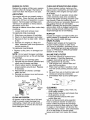
This product
haspreviously
a low emission
engine which
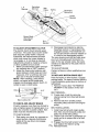
engine, read and understand this Owner's Manual.
IMPORTANT:
For answers to your questions
Read and follow all Safety
Rules and Instructions before
about this product, Call:
operating this equipment.
Sears Craftsman Help Line
5 am - 5 pm, Mon- Sat
1-800-659-5917
Sears, Roebuck and Co., Hoffman Estates,
Visit our Craftsman website:www.sears.com/craftsman
IL 60179 U.S.A.
Warranty ................................................
2
Safety Rules ..........................................
3
Product Specifications ........................... 5
Assembly/P re-Operation ....................... 7
Operation ...............................................
9
Maintenance Schedule ........................ 16
Maintenance ........................................
16
Service and Adjustments ..................... 20
Storage ................................................
28
Troubleshooting ................................... 29
Repair Parts .........................................
34
Sears Service ........................ Back Cover
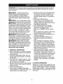
LIMITED WARRANTY ON CRAFTSMAN RIDING EQUIPMENT
For two (2) years from the date of purchase, if this Craftsman Riding Equipment is
maintained, lubricated and tuned up according to the instructions in the owner's manual,
Sears will repair or replace free of charge any parts that are found to be defective in
material or workmanship according to the guidelines of coverage listed below. Sears will
also provide free labor for these applicable warranted parts for the two full years. During
the first 30 days of purchase, there will be no charges to service the product at your
home for issues covered by this warranty. (See exclusions below). For your convenience, IN HOME warranty service will still be available after the first 30 days of purchase, but a trip charge will apply. This charge will be waived if the Craftsman product is
dropped off at an authorized Sears location. For the nearest authorized Sears location,
please call 1-800-4-MY-HOME®.
This warranty applies only while this product is within
the United States.
This Warranty does not cover:
• Expendable items which become worn during normal use, including but not limited to
blades, spark plugs, air cleaners, belts, and oil filters.
• Standard Maintenance Servicing, oil changes, or tune-ups
• Tire replacement or repair caused by punctures from outside objects, such as nails,
thorns, stumps, or glass.
• Repairs necessary because of operator abuse, including but not limited to, damage
caused by towing objects beyond the capability of the riding equipment, impacting
objects that bend the frame or crankshaft, or over-speeding the engine.
• Repairs necessary because of operator negligence, including but not limited to, electrical and mechanical damage caused by improper storage, failure to use the proper
grade and amount of engine oil, failure to keep the deck clear of flammable debris,
or failure to maintain the equipment according to the instructions contained in the
owner's manual.
• Engine (fuel system) cleaning or repairs caused by fuel determined to be contaminated or oxidized (stale). In general, fuel should be used within 30 days of its purchase date.
• Normal deterioration and wear of the exterior finishes, or product label replacement.
• Riding equipment used for commercial or rental purposes.
LIMITED WARRANTY ON BATTERY
For ninety (90) days from date of purchase, if any battery included with this riding equipment proves defective in material or workmanship and our testing determines the battery
will not hold a charge, Sears will replace the battery at no charge. During the first 30
days of purchase, there will be no charges to replace the battery at your HOME. After
the first 30 days, for your convenience, IN-HOME warranty service will still be available but a trip charge will apply. This charge will be waived if the Craftsman product is
dropped off at an authorized Sears location. For the nearest authorized Sears location,
please call 1-800-4-MY-HOME®.
This battery warranty applies only while this product is within the United States.
This warranty gives you specific legal rights, and you may also have other rights, which
vary, from state to state.
Sears, Roebuck and Co.,Dept.817WA, Hoffman Estates, IL 60179
2
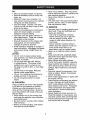
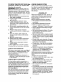
IMPORTANT: This cutting machine is capable of amputating hands and feet and throwing objects. Failure to observe the following safety instructions could result in serious
injury or death.
• Be aware of the mower discharge direction and do not point it at anyone. Do
not operate the mower without either
the entire grass catcher or the guard in
place.
• Slow down before turning.
• Never leave a running machine unattended. Always turn off blades, set
parking brake, stop engine, and remove
keys before dismounting.
• Turn off blades when not mowing.
• Stop engine before removing grass
catcher or unclogging chute.
• Mow only in daylight or good artificial
light.
• Do not operate the machine while under
the influence of alcohol or drugs.
• Watch for traffic when operating near or
crossing roadways.
• Use extra care when loading or unloading the machine into a trailer or
truck.
• Data indicates that operators, age 60
years and above, are involved in a large
percentage of riding mower-related injuries. These operators should evaluate
their ability to operate the riding mower
safely enough to protect themselves and
others from serious injury.
• Keep machine free of grass, leaves or
other debris build-up which can touch
hot exhaust / engine parts and burn. Do
not allow the mower deck to plow leaves
or other debris which can cause buildup to occur. Clean any oil or fuel
spillage before operating or storing the
machine. Allow machine to cool before
storage.
_WARNING:
In order to prevent accidental starting when setting up, transporting, adjusting or making repairs,
always disconnect spark plug wire and
place wire where it cannot contact spark
plug.
_WARNING:
Do not coast down a hill in
_utral, you may lose control of the tractor.
WARNING: Tow only the attachments
that are recommended by and comply with
specifications of the manufacturer of your
tractor. Use common sense when towing.
Operate only at the lowest possible speed
when on a slope. Too heavy of a load,
while on a slope, is dangerous. Tires can
lose traction with the ground and cause
_u to lose control of your tractor.
WARNING: Engine exhaust, some of its
constituents, and certain vehicle components contain or emit chemicals known to
the State of California to cause cancer and
,_th defects or other reproductive harm.
WARNING: Battery posts, terminals
and related accessories contain lead and
lead compounds, chemicals known to the
State of California to cause cancer and
birth defects or other reproductive harm.
Wash hands after handling.
I. GENERAL
OPERATION
• Read, understand, and follow all instructions in the manual and on the machine
before starting.
• Only allow responsible adults, who are
familiar with the instructions, to operate
the machine.
• Clear the area of objects such as rocks,
toys, wire, etc., which could be picked
up and thrown by the blade.
• Be sure the area is clear of other people
before mowing. Stop machine if anyone
enters the area.
• Never carry passengers.
• Do not mow in reverse unless absolutely necessary. Always look down and
behind before and while backing.
II. SLOPE OPERATION
Slopes are a major factor related to lossof-control and tipover accidents, which can
result in severe injury or death. All slopes
require extra caution. If you cannot back
up the slope or if you feel uneasy on it, do
not mow it.
3
DO:
• Never carry children. They may fall off
and be seriously injured or interfere with
safe machine operation.
• Never allow children to operate the
machine.
• Use extra care when approaching blind
corners, shrubs, trees, or other objects
that may obscure vision.
• Mow up and down slopes, not across.
• Remove obstacles such as rocks, tree
limbs, etc.
• Watch for holes, ruts, or bumps. Uneven terrain could overturn the machine.
Tall grass can hide obstacles.
• Use slow speed. Choose a low gear
so that you will not have to stop or shift
while on the slope.
• Follow the manufacturer's recommendations for wheel weights or counterweights to improve stability.
• Use extra care with grass catchers or
other attachments. These can change
the stability of the machine.
• Keep all movement on the slopes slow
and gradual Do not make sudden
changes in speed or direction.
• Avoid starting or stopping on a slope. If
tires lose traction, disengage the blades
and proceed slowly straight down the
slope.
DO NOT:
• Do not turn on slopes unless necessary, and then, turn slowly and gradually
downhill, if possible.
• Do not mow near drop-offs, ditches,
or embankments. The mower could
suddenly turn over if a wheel is over
the edge of a cliff or ditch, or if an edge
caves in.
• Do not mow on wet grass. Reduced
traction could cause sliding.
• Do not try to stabilize the machine by
putting your foot on the ground.
• Do not use grass catcher on steep
slopes.
IV. SERVICE
• Use extra care in handling gasoline and
other fuels. They are flammable and
vapors are explosive.
- Use only an approved container.
- Never remove gas cap or add fuel
with the engine running. Allow
engine to cool before refueling. Do
not smoke.
- Never refuel the machine indoors.
- Never store the machine or fuel container inside where there is an
open flame, such as a water heater.
• Never run a machine inside a closed
area.
• Keep nuts and bolts, especially blade
attachment bolts, tight and keep equipment in good condition.
• Never tamper with safety devices.
Check their proper operation regularly.
• Keep machine free of grass, leaves, or
other debris build-up. Clean oil or fuel
spillage. Allow machine to cool before
storing.
• Stop and inspect the equipment if you
strike an object. Repair, if necessary,
before restarting.
• Never make adjustments or repairs with
the engine running.
• Grass catcher components are subject
to wear, damage, and deterioration,
which could expose moving parts or
allow objects to be thrown. Frequently
check components and replace with
manufacturer's recommended parts,
when necessary.
• Mower blades are sharp and can cut.
Wrap the blade(s) or wear gloves, and
use extra caution when servicing them.
• Check brake operation frequently. Adjust and service as required.
III, CHILDREN
Tragic accidents can occur if the operator
is not alert to the presence of children.
Children are often attracted to the machine and the mowing activity. Neverassume that children will remain where you
last saw them.
• Keep children out of the mowing area
and under the watchful care of another
responsible adult.
• Be alert and turn machine off if children
enter the area.
• Before and when backing, look behind
and down for small children.
4
• Be sure the area is clear of other people
before mowing. Stop machine if anyone
enters the area.
• Never carry passengers or children
even with the blades off.
• Do not mow in reverse unless absolutely necessary. Always look down and
behind before and while backing.
• Never carry children. They may fall off
and be seriously injured or interfere with
safe machine operation.
• Keep children out of the mowing area
and under the watchful care of another
responsible adult.
• Be alert and turn machine off if children
enter the area.
• Before and when backing, look behind
and down for small children.
• Mow up and down slopes (15 ° Max), not
across.
• Remove obstacles such as rocks, tree
limbs, etc.
• Watch for holes, ruts, or bumps. Uneven
terrain could overturn the machine. Tall
grass can hide obstacles.
• Use slow speed. Choose a low gear
so that you will not have to stop or shift
while on the slope.
• Avoid starting or stopping on a slope. If
tires lose traction, disengage the blades
and proceed slowly straight down the
slope.
• If machine stops while going uphill,
disengage blades, shift into reverse and
back down slowly.
• Be not turn on slopes unless necessary,
and then, turn slowly and gradually
downhill, if possible.
PRODUCT
CONGRATULATIONS
on your purchase
of a new tractor. It has been designed,
engineered and manufactured to give
you the best possible dependability and
performance.
Should you experience any problem you
cannot easily remedy, please contact a
Sears or other qualified service center.
We have competent, well-trained technicians and the proper tools to service or
repair this tractor.
Please read and retain this manual. The
instructions will enable you to assemble
and maintain your tractor properly. Always
observe the "SAFETY RULES".
SPECIFICATIONS
Gasoline
Capacity
and Type:
5.0 Gallons
Unleaded
Regular
Oil Type
API-SF-SJ):
SAE 10W30
(above 32°F)
SAE 5W-30
(below 32°F)
Oil Capacity:
W/Filter:
4.0 Pints
W/O Filter: 3.5 Pints
Spark Plug:
(Gap: .030")
Champion
RC12YC
Ground Speed (MPH):
Forward: 0 - 5.8
Reverse: 0 - 2.1
Tire Pressure:
Charging
System:
Battery:
Front:
Rear:
CUSTOMER
RESPONSIBILITIES
• Read and observe the safety rules.
• Follow a regular schedule in maintaining, caring for and using your tractor.
• Follow the instructions under"Maintenance" and "Storage" sections of this
owner's manual.
14 PSI
10PSI
15 AMPS @ 3600RpM
Amp/Hr:
35
Min. CCA: 280
Case size: U1R
Blade Bolt Torque: 45-55 Ft. Lbs_
5
Here's what's included in the Agreement:
• Expert service by our 12,000 profesional repair specialists.
• Unlimited service and no charge for
parts and labor on all covered repairs.
• Product replacement if your covered
product can't be fixed.
• Discount of 10% from regular price of
service and service-related parts not
covered by the agreement; also, 10%
off regular price of preventive maintenance check.
• Fast help by phone - phone support
from a Sears technician on products
requiring in-home repair, plus convenient repair scheduling.
Once you purchase the Agreement, a
simple phone call is all that it takes for you
to schedule service. You can call anytime
day or night, or schedule a service appointment online.
Sears has over 12,000 professional repair
specialists, who have access to over 4.5
million quality parts and accessories.
That's the kind of professionalism you can
count on to help prolong the life of your
new purchase for years to come. Purchase
your Repair Protection Agreement today!
Some limitations
and exclusions
apply.
For prices and additional
information
call 1-800-827-6655.
4_kWARNING: This tractor is equipped
with an internal combustion engine and
should not be used on or near any unimproved forest-covered, brush-covered or
grass-covered land unless the engine's
exhaust system is equipped with a spark
arrester meeting applicable local or state
laws (if any). If a spark arrester is used, it
should be maintained in effective working
order by the operator.
In the state of California the above is required by law (Section 4442 of the California Public Resources Code). Other states
may have similar laws. Federal laws apply
on federal lands. A spark arrester for the
muffler is available through your nearest
Sears service center (See REPAIR PARTS
section of this manual).
REPAIR PROTECTION
AGREEMENTS
Congratulations on making a smart purchase. Your new Craftsman@ product is
designed and manufactured for years of
dependable operation. But like all products,
it may require repair from time to time. That's
when having a Repair Protection Agreement
can save you money and aggravation.
Purchase a Repair Protection Agreement
now and protect yourself from unexpected
hassle and expense.
SEARS
INSTALLATION
SERVICE
For Sears professional installation of home
appliances, garage door openers, water
heaters, and other major home items, in
the U.S.A. call 1-800-4-MY-HOME®
I Video Cassette
IF
I
Keys
]
dll!ll
[ LeMv°elWerg
II wreo qlul
(4) Lockwasher
I
I _''-
{2)Hex
Bolts
(1) Oil Drain Tub e _
5/16-18 x 3/4
6
Slope Sheet
Your new tractor has been assembled at the factory.
you begin.
Review the video cassette before
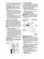
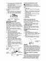
2. Release L.H. seat slide on seat pan by
pulling out on adjustment handle and
sliding it to the rear position exposing
seat mounting holes from bottom. Slide
R.H. slide to same rear position.
3. Mount rear of seat on slides using
mounting bolts and lock washers as
shown.
4. Pull out on adjustment handle and
slide seat all the way forward. Install
front mounting bolts and lock washers.
Tighten all mounting bolts securely.
5. Lower seat into operating position and
sit on seat. Press clutch/brake pedal all
the way down. If operating position is
not comfortable, adjust seat.
To adjust seat: Grasp adjustment handle
and pull out, slide seat to desired position
and release adjustment handle.
When right or left hand is mentioned in
this manual, it means, from your point of
view, when you are in the operating position (seated behind the steering wheel).
TO REMOVE TRACTOR
FROM
CARTON
UNPACK CARTON
1. Cut along dotted lines on all four panels of carton. Remove end panels and
lay side panels flat.
2. Remove packing materials.
3. Remove protective materials from tractor hood and grille.
IMPORTANT: Check for and remove any
staples in skid that may puncture tires
where tractor is to roll off skid.
HOW TO SET UP YOUR TRACTOR
CHECK BATTERY
Seat
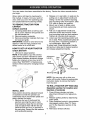
1. Lift hood to raised position.
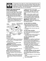
NOTE: If this battery is put into service
after month and year indicated on label
(label located between terminals) charge
battery for minimum of one hour at 6-10
amps. (See "BATTERY" in Maintenance
section of this manual for charging instructions).
L.h. Seat_
Handle\
\
Seat
Pan
Loc.\ /
Adjustment
Washer
l___
,_
_
. -"
.-
-
R.H. Seat Slide
Mountln0
Bo,ts
Label
NOTE: You may now roll or drive your
tractor off the skid. Follow the appropriate
instruction below to remove the tractor
from the skid.
J
TO ROLLTRACTOR
OFF SKID (See
Operation
section for location and
function of controls)
1. Press lift lever plunger and raise
attachment lift lever to its highest position.
2. Release parking brake by depressing
brake pedal.
3. Place freewheel control in transmission
disengaged position (See "To Transport" in the Operation section of this
manual).
4. Roll tractor forward off skid.
INSTALL SEAT
Seat position should be adjusted forward
or backward so that the operator can
comfortably reach clutch/brake pedal and
safely operate the tractor.
1. Remove the two (2) bolts and flat
washers securing the seat to cardboard packing. Keep the two (2) bolts
only and place them with the two (2)
identical bolts and four (4) washers in
the parts bag. Discard the flat washers
and cardboard packing.
7
CHECK
TO DRIVE TRACTOR
OFF SKID (See
Operation
section for location and
function of controls)
_WARNING:
Before starting, read, understand and follow all instructions in the
Operation section of this manual. Be sure
tractor is in a well-ventilated area. Be sure
the area in front of tractor is clear of other
people and objects.
1. Be sure all the above assembly steps
have been completed.
2. Check engine oil level and fill fuel tank
with gasoline.
3. Place freewheel control in "transmission engaged" position (See "To
Transport" in the Operation section of
this manual).
4. Sit on seat in operating position, depress brake pedal and set the parking
brake.
5. Press lift lever plunger and raise
attachment lift lever to its highest position.
6. Start the engine. After engine has
started, move throttle control to idle
position.
7. Release parking brake.
8. Slowly move the motion control lever
forward and slowly drive tractor off
skid.
9. Apply brake to stop tractor and set
parking brake.
10.Turn ignition key to "STOP" position.
Continue with the instructions that follow.
SYSTEM
After you learn how to operate your tractor, check to see that the brake is properly
adjusted. See "TO ADJUST BRAKE" in
the Service and Adjustments section of
this manual.
,/CHECKLIST
Before you operate your new tractor, we
wish to assure that you receive the best
performance and satisfaction from this
Quality Product.
Please review the following checklist:
,/All assembly instructions have been
completed.
,/No remaining loose parts in carton.
,/Battery is properly prepared and
charged.
(Minimum 1 hour at 6 amps).
,/Seat is adjusted comfortably and tightened securely.
,/All tires are properly inflated. (For shipping purposes, the tires were overinflated at the factory).
,/Be sure mower deck is properly leveled
side-to-side/front-to-rear
for best cutting
results. (Tires must be properly inflated
for leveling).
,/Check mower and drive belts. Be sure
they are routed properly around pulleys
and inside all belt keepers.
,/Check wiring. See that all connections
are still secure and wires are properly
clamped.
,/Before driving tractor, be sure freewheel
control is in "transmission engaged"
position (see "TO TRANSPORT" in the
Operation section of this manual).
While learning how to use your tractor, pay
extra attention to the following important
items:
,/Engine oil is at proper level.
,/Fuel tank is filled with fresh, clean, regular unleaded gasoline.
,/Become familiar with all controls, their
location and function. Operate them
before you start the engine.
,/Be sure brake system is in safe operating condition.
,/It is important to purge the transmission
before operating your tractor for the first
time. Follow proper starting and transmission purging instructions (See "TO
START ENGINE" and "PURGE TRANSMISSION" in the Operation section of
this manual).
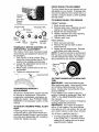
CHECKTIRE
PRESSURE
The tires on your tractor were overinflated
at the factory for shipping purposes. Correct tire pressure is important for best
cutting performance.
• Reduce tire pressure to PSI shown in
"PRODUCT SPECIFICATIONS" section
of this manual.
CHECK DECK LEVELNESS
For best cutting results, mower housing should be properly leveled. See "TO
LEVEL MOWER HOUSING" in the Service
and Adjustments section of this manual.
CHECK FOR PROPER
OF ALL BELTS
BRAKE
POSITION
See the figures that are shown for replacing motion and mower blade drive belts
in the Service and Adjustments section
of this manual. Verify that the belts are
routed correctly.
8
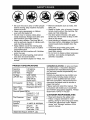
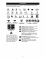
These symbols may appear on your tractor or in literature supplied with the product.
Learn and understand their meaning.
R
N
REVERSE
ENGINE
OFF
H
NEUTRAL
HIGH
LIGHTS ON
OVER TEMP
LIGHT
FUEL
ATTACHMENT
CLUTCH ENGAGED
ENGINE ON
OIL PRESSURE
ATTACHMENT
CLUTCH DISENGAGED
&
Failure
to follow
instructions
could result in serious
ENGINE
BATTERY
injury or
death. The safety alert symbol
is used to identify safety information about hazards which can
result in death, serious injury
and/or property damage.
CHOKE
START
FAST
PARKING
REVERSE
DANGER, KEEP HANDS
AND FEET AWAY
&
&
&
FREE WHEEL
(Automatic Models only)
I'.,I
L
LOW
BRAKE
FORWARD
SLOW
IGNITION
PARKING BRAKE
LOCKED
MOWER
KEEP AREA CLEAR
(SEE SAFETY
HEIGHT
SLOPE
PARKING BRAKE
UNLOCKED
MOWER
LIFT
HAZARDS
RULES SECTION)
DANGER indicates a hazard which, if not avoided,
will result in death or serious injury.
WARNING indicates a hazard which, if not avoided,
could result in death or serious injury.
CAUTION indicates a hazard which, if not avoided,
might result in minor or moderate injury.
CAUTION when used without the alert symbol,
indicates a situation that could result in damage
to the tractor and/or engine.
_HOT
SURFACES indicates a hazard which,
,,g_,., if not avoided, could result in death, serious injury
and/or property damage.
FIRE indicates a hazard which, if not avoided,
could result in death, serious injury and/or
property damage.
9
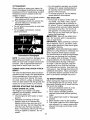
KNOW YOUR TRACTOR
READ THIS OWNER'S MANUAL AND SAFETY RULES BEFORE OPERATING YOUR
TRACTOR
Compare the illustrations with your tractor to familiarize yourself with the locations of
various controls and adjustments. Save this manual for future reference.
Ammeter
Choke
Hou
ht Switch
Ignition Switch
Position
Attachment
Clutch Switch
Throttle
Motion Drive
Belt Tension
Handle
Lever
Plunger
Control
Attachment
Lift Lever
Parking Brake
Lever
Motion Control
Lever
Height
Adjustment
Knob
Free Wheel
02656
Our tractors conform to the safety standards of the
American National Standards Institute.
ATTACHMENT CLUTCH SWITCH - Used
to engage the mower blades, or other attachments mounted to your tractor.
LIGHT SWITCH POSITION - Turns the
headlights on and off.
THROTTLE CONTROL - Used to control
engine speed.
BRAKE PEDAL - Used for braking the
tractor and starting the engine.
CHOKE CONTROL - Used when starting
a cold engine.
HEIGHT ADJUSTMENT KNOB - Used to
adjust the mower cutting height.
IGNITION SWITCH - Used for starting and
stopping the engine.
ATTACHMENT LIFT LEVER - Used to
raise and lower the mower deck or other
attachments mounted to your tractor.
LIFT LEVER PLUNGER - Used to release
attachment lift lever when changing its
position.
AMMETER - Indicates charging (+) or
discharging (-) of battery.
PARKING BRAKE LEVER - Locks brake
pedal into the brake position.
MOTION CONTROL LEVER - Selects the
speed and direction of tractor.
FREEWHEEL CONTROL - Disengages
transmission for pushing or slowly towing
the tractor with the engine off.
MOTION DRIVE BELTTENSlON
HAN
DLE- Used when changing motion drive
belt and, if necessary, starting engine
under extremely cold conditions.
TACHOMETER - Measures the speed of
your engine in revolutions per minute (RPM).
HOURMETER - Indicates hours of operation.
10
The operation of any tractor can result in foreign objects thrown into
the eyes, which can result in severe eye damage. Always wear safety
glasses or eye shields while operating your tractor or performing any
adjustments or repairs. We recommend standard safety glasses or a
wide vision safety mask worn over spectacles.
HOW TO USE YOUR TRACTOR
• Never use choke to stop engine.
IMPORTANT: Leaving the ignition switch
in any position other than "STOP" will
cause the battery to discharge and go
dead.
NOTE: Under certain conditions when
tractor is standing idle with the engine
running, hot engine exhaust gases may
cause "browning" of grass. To eliminate
this possibility, always stop engine when
TO SET PARKING BRAKE
Your tractor is equipped with an operator
presence sensing switch. When engine
is running, any attempt by the operator
to leave the seat without first setting the
parking brake will shut off the engine.
1. Depress brake pedal all the way down
and hold.
2. Pull parking brake lever up and release
pressure from brake pedal. Pedal
should remain in brake position. Make
sure parking brake will hold tractor
_Ocpping trac!or on grass areas.
AUTION. Always stop tractor completely, as described above, before leaving
the operator's position.
secure.
Choke
Control
_
Push-In to
Attachment Clutch
Switch Pull Out to
"Engage"
TO USETHROTTLE
Always operate engine at full throttle.
• Operating engine at less than full
throttle reduces the battery charging
rate.
• Full throttle offers the best mower performance.
Throttle
Control
•Motion
Control
Pedal
Knob
Brake Pedal
"Drive" Position
"Disengaged"
Position
TO USE CHOKE CONTROL
Use choke control whenever you are starting a cold engine. Do not use to start a
warm engine.
• To engage choke control, pull knob out.
Slowly push knob in to disengage.
Parking Brake
"Engaged"
Position
STOPPING
TO MOVE
MOWER
BACKWARD
BLADES
-
DRIVE-
• To stop ground drive, depress brake
pedal all the way down.
IMPORTANT: The motion control lever
returns to neutral (N) position when the
brake pedal is fully depressed.
ENGINE • Move throttle
control
between
FORWARD
AND
CAUTION: Do not attempt to operate motion control lever when the parking brake
is set or when the brake pedal is depressed. Doing so may result in misadjustment to the drive control system.
The direction and speed of movement is
controlled by the motion control lever.
1. Start tractor with motion control lever in
neutral (N) position.
2. Release parking brake.
3. Slowly move motion control lever to
desired position.
• To stop mower blades, push attachment
clutch switch in to disengaged position.
GROUND
CONTROL
half and
full speed (fast) position.
NOTE: Failure to move throttle control
TO ADJUST
between half and full speed (fast) position, before stopping, may cause engine to
"backfire".
• Turn ignition key to "STOP" position and
remove key. Always remove key when
leaving tractor to prevent unauthorized
use.
11
MOWER
CUTTING
HEIGHT
The cutting height is controlled by turning the height adjustment knob in desired
direction.
• Turn knob clockwise (J_) to raise cutting
height.
• Turn knob counterclockwise (,_) to
lower cutting height.
The cutting height range is approximately
1-1/2"to 4-1/2". The heightsare measured from the ground to the bladetip with
the engine not running.
These heightsare approximateand may
vary dependingupon soil conditions,
height of grass and types of grass being
mowed.
• The averagelawn shouldbe cut to
approximately2-1/2 inches during the
cool season and to over 3 inches during
hot months. For healthierand better
lookinglawns,mow often and after
moderategrowth.
• For best cutting performance,grass over
6 inches in height should be mowed
twice. Makethe first cut relativelyhigh;
the second to desired height.
TO OPERATE
MOWER
Your tractor is equipped with an operator
presence sensing switch. Any attempt
by the operator to leave the seat with the
engine running and the attachment clutch
engaged will shut off the engine.
1. Select desired height of cut.
2. Lower mower with attachment lift control.
3. Start mower blades by engaging attachment clutch control.
TO STOP MOWER BLADES ,_Scengage attachment clutch control.
AUTION: Do not operate the mower
without either the entire grass catcher,
on mowers so equipped, or the deflector
shield in place.
Attachemnt Lift
Attachment Clutch
TO ADJUST GAUGEWHEELS
Lever High Position
Switch Pull Out to
Gaugewheels are properly adjusted
"Engage"
when they are slightly off the groundwhen
moweris at the desiredcutting height in
operatingposition.Gaugewheels then
keepthe deck in proper positionto help
preventscalpingin most terrainconditions.
Position
NOTE: Be sure tractor is on a flat level
surface.
1. Lower mowerandadjust mowerto
desiredcutting height.
Push--In to
2. Removeretainerspring and clevis pin
"Disengage"
which secureeach gauge wheel bar.
3. Lowergauge wheels to ground. Raise
gaugewheels slightly to align holes
in bracketand gauge wheel bar and
Deflector
insert clevis pin.Gauge wheelsshould
Shield
be slightly off the ground.
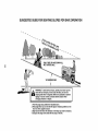
TO OPERATE ON HILLS
4. Replaceretainerspring into clevis pin.
,JC_WARNING: De not drive up or down
5. Be sure all gauge wheels are in the
hills with slopes greater than 15 ° and do
same setting.
not drive across any slope. Use the slope
IMPORTANT:Be sure to readjust gauge
guide provided at the back of this manual.
wheels if you changethe cutting height
of the mowerdeck.
• Choose the slowest speed before start-
ing up or down hills.
• Avoid stopping or changing speed on
hills.
• If stopping is absolutely necessary, push
brake pedal quickly to brake position
and engage parking brake.
IMPORTANT: The motion control lever
returns to neutral (N) position when the
brake pedal is depressed.
• To restart movement, slowly release
parking brake and brake pedal.
• Slowly move motion control lever to
slowest setting.
• Make all turns slowly.
Retainer
Spring
Clevis
Pin
12
TOTRANSPORT
• For cold weather operation you should
change oil for easier starting (See the
oil viscosity chart in the Maintenance
section of this manual).
• To change engine oil, see the Maintenance section in this manual.
ADD GASOLINE
• Fill fuel tank to bottom of filler neck. Do
not overfill. Use fresh, clean, regular
unleaded gasoline with a minimum of
87 octane. (Use of leaded gasoline will
increase carbon and lead oxide deposits
and reduce valve life). Do not mix oil
with gasoline. Purchase fuel in quantities that can be used within 30 days to
assure fuel freshness.
A(_CAUTION: Wipe off any spilled oil or
fuel. Do not store, spill or use gasoline
near an open flame.
IMPORTANT: When operating in temperatures below32°F(0°C), use fresh, clean
winter grade gasoline to help insure good
cold weather starting.
CAUTION: Alcohol blended fuels (called
gasohol or using ethanol or methanol) can
attract moisture which leads to separation and formation of acids during storage.
Acidic gas can damage the fuel system
of an engine while in storage. To avoid
engine problems, the fuel system should
be emptied before storage of 30 days
or longer. Drain the gas tank, start the
engine and let it run until the fuel lines
and carburetor are empty. Use fresh fuel
next season. See Storage Instructions for
additional information. Never use engine
or carburetor cleaner products in the fuel
tank or permanent damage may occur.
When pushing or towing your tractor, be
sure to disengage transmission by placing
freewheel control in freewheeling position.
Freewheel control is located at the rear
drawbar of tractor.
1. Raise attachment lift to highest position
with attachment lift control.
2. Pull freewheel control out and into the
slot and release so it is held in the
disengaged position.
• Do not push or tow tractor at more than
two (2) MPH.
• To re-engage transmission, reverse
above procedure.
Transmission
Transmission
En
Disengaged
NOTE: To protect hood from damage when
transporting your tractor on a truck or a
trailer, be sure hood is closed and secured
to tractor. Use an appropriate means of
tying hood to tractor (rope, cord, etc.).
TOWING
MENTS
CARTS
AND
OTHER
ATTACH-
Tow only the attachments that are recommended by and comply with specifications
of the manufacturer of your tractor. Use
common sense when towing. Too heavy
of a load, while on a slope, is dangerous.
Tires can lose traction with the ground and
cause you to lose control of your tractor.
TO START ENGINE
When starting the engine for the first time
or if the engine has run out of fuel, it will
take extra cranking time to move fuel from
the tank to the engine.
1. Be sure freewheel control is in the
transmission engaged position.
2. Sit on seat in operating position,
depress brake pedal and set parking
brake.
3. Move attachment clutch to "disengage"
position.
4. Move throttle control to fast position
5. Pull choke control out for a cold engine
start attempt. For a warm engine start
attempt the choke control may not be
needed.
BEFORE STARTING THE ENGINE
CHECK ENGINE OIL LEVEL
The engine in your tractor has been
shipped, from the factory, already filled
with summer weight oil.
1. Check engine oil with tractor on level
ground.
2. Unthread and remove oil fill cap/
dipstick; wipe oil off. Reinsert the
dipstick into the tube and rest oil fill
cap on the tube. Do not thread the cap
onto the tube. Remove and read oil
level. If necessary, add oil until "FULl"
mark on dipstick is reached. Do not
overfill.
13
NOTE: Beforestarting, read the warm and
cold starting proceduresbelow.
6. Insert key into ignition and turn key
clockwiseto start positionand release
keyas soon as enginestarts. Do
not run starter continuouslyfor more
than fifteen secondsper minute.If the
enginedoes not start after several
attempts,push chokecontrol in, wait
a few minutesand try again. If engine
still does not start, pull the chokecontrol out and retry.
WARMWEATHERSTARTING(50° F and
above)
7. When engine starts, slowly push choke
control in untilthe engine begins to
run smoothly.If the enginestarts to
run roughly,pull the chokecontrolout
slightly for a few seconds and then
continueto push the control in slowly.
• The attachmentsand grounddrive can
now be used.If the engine does not
acceptthe load, restartthe engine and
allow it to warm up for one minuteusing
the chokeas describedabove.
COLD WEATHERSTARTING(50° F and
below)
7. When engine starts, slowly push choke
control in untilthe engine begins to run
smoothly.Continueto pushthe choke
control in smallsteps allowingthe engine to accept small changes in speed
and load, untilthe choke controlis fully
in. If the engine starts to run roughly,
pull the chokecontrol out slightly for
a few seconds and then continueto
push the control in slowly.This may
requirean enginewarm-up period from
severalseconds to severalminutes,
dependingon the temperature.
NOTE: In extremecold conditions,if
enginewill not start you may need to disengagethe motiondrive belt as follows:
1. Be sure parkingbrake is engaged.
2. Removeretainerspring from the drive
belt tension handleto relievebelt tension.
3. Start engineand allow it to warm up
for three (3) minutes.
4. Shut-offengine and engageparking
brake.
5. Engagedrive belt tension handleand
replacethe retainerspring.
14
AUTOMATICTRANSMISSIONWARMUP
Beforedriving the unit in cold weather,
the transmissionshould be warmed up as
follows:
1. Be sure the tractor is on levelground.
2. Placethe motioncontrol leverin
neutral.Releasethe parking brakeand
let the brakeslowly returnto operating
position.
3. Allow one minutefortransmissionto
warm up.This can be done during the
enginewarm up period.
• The attachmentscan be used during
the engine warm-up periodafter the
transmissionhas been warmed up and
may requirethe choke controlbe pulled
out slightly.
NOTE: If at a high altitude (above3000
feet) or in cold temperatures(below32 F)
the carburetorfuel mixturemay need to
be adjustedfor best engineperformance.
(See "TOADJUST CARBURETOR"in the
Serviceand Adjustmentssection of this
manual).
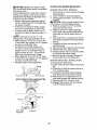
PURGE TRANSMISSION
_CAUTION: Neverengage or disengage
freewheelleverwhilethe engineis running.
Toensure proper operationand performance,it is recommendedthat the
transmissionbe purged beforeoperating
tractorfor the first time.This procedurewill
removeany trapped air insidethe transmission which may havedevelopedduring
shippingof your tractor.
IMPORTANT: Should your transmission
require removalfor service or replacement, it should be purged after reinstallation beforeoperatingthe tractor.
1. Placetractor safely on levelsurface
with engine off and parking brakeset.
2. Disengagetransmissionby placing freewheelcontrolin disengaged
position (See"TOTRANSPORT'in this
sectionof manual).
3. Sitting in the tractorseat, start engine.
After the engine is running, move
throttle controlto slow position.Disengage parkingbrake.
4. Move motioncontrol leverto full
forwardpositionand hold for five (5)
seconds.Move leverto full reverse
positionand hold for five (5) seconds.
Repeat this procedurethree (3) times.
NOTE: Duringthis step there will be no
movementof drive wheels.The air is being
removedfrom hydraulicdrive system.
5. Move motion control lever to neutral
(N) position. Shutoff engine and set
parking brake.
6. Engage transmission by placing freewheel control in engaged position (See
"TO TRANSPORT' in this section of
manual).
7. Sitting in the tractor seat, start engine.
After the engine is running, move
throttle control to half (1/2) speed.
Disengage parking brake.
8. Slowly move motion control lever forward, after the tractor moves approximately five (5) feet, slowly move motion
control lever to reverse position. After
the tractor moves approximately five
(5) feet return the motion control lever
to the neutral (N) position. Repeat this
procedure with the motion control lever
three (3) times.
Your transmission is now purged and now
ready for normal operation.
f
l
I
t"
(
,,
•
]1
J
o
=
J
00272
• If grass is extremely tall, it should be
mowed twice to reduce load and possible fire hazard from dried clippings.
Make first cut relatively high; the second
to the desired height.
• Do not mow grass when it is wet.
Wet grass will plug mower and leave
undesirable clumps. Allow grass to dry
before mowing.
• Always operate engine at full throttle
when mowing to assure better mowing performance and proper discharge
of material. Regulate ground speed by
selecting a low enough gear to give the
mower cutting performance as well as
the quality of cut desired.
• When operating attachments, select a
ground speed that will suit the terrain
and give best performance of the attachment being used.
MOWING TIPS
• Tire chains cannot be used when the
mower housing is attached to tractor.
• Mower should be properly leveled for
best mowing performance. See "TO
LEVEL MOWER HOUSING" in the
Service and Adjustments section of this
manual.
• The left hand side of mower should be
used for trimming.
• Drive so that clippings are discharged
onto the area that has already been
cut. Have the cut area to the right of
the tractor. This will result in a more
even distribution of clippings and more
uniform cutting.
• When mowing large areas, start by
turning to the right so that clippings will
discharge away from shrubs, fences,
driveways, etc. After one or two rounds,
mow in the opposite direction making
left hand turns until finished.
15
MAINTENANCE
SCHEDULE
FiLL
,NOATES
AS YOU
COMPLETE
._'__"_0_*'_,_
R EGU LARSE RVICE
Check
Check
T
R
.___
_
11_5
Lubrication
_1_43
Check
Transaxle
V'
Check
V_Belts
Check
Engine
Oil Level
I_
Oil (with
E
Change
Engine
Oil (without
N
G
CleanAirFilter
Clean
Air Screen
NI
Inspect
E
Replace
Muffler/Spark
Oil Filter
_1,2
oil filter)
_1,2
Replace
Air Filter
Replace
Fuel
Arrester
(If equipped)
Cooling
Spark
_l_,_
Fins
_
Plug
_
Paper
Cartridge
9_'2
Filter
when
I_
operating
ambient
temperatures.
more often when
operating
GENERAL
I_
oil filter)
_:
Replace
in high
2 = Service
I_
Cooling
Engine
often
DATES
I_
Change
more
_bR.
_
I_
Chart
Engine
_4,--_
I_
Fasteners
Check
Battery LevelMower Blades
Sharpen/Replace
Ctean Battery and Terminals
1 = Change
A
and
0
Clean
_,'_
_p"
S E RVICE
T
R
4. °;
_.._
_'
Check Operator
Presence
Interlock
Systems
for Loose
R4. _
i__t_'d_"
Brake Operation
Tire Pressure
Check
._o_So_
under
a heavy
in dirty
or dusty
load
or
3 = Replace
blades
more often when
mowing
in sandy
soil.
4 - NOt required
if equipped
with maintenance-free
battery.
S = Tighten
front axle pivOt bolt to 35 ft.=lbs, maximum.
Do not overtighten.
conditions.
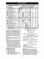
RECOMMENDATIONS
LUBRICATION
The warranty on this tractor does not
cover items that have been subjected to
operator abuse or negligence. To receive
full value from the warranty, operator
must maintain tractor as instructed in this
manual.
Some adjustments will need to be made
periodically to properly maintain your
tractor.
All adjustments in the Service and Adjustments section of this manual should be
checked at least once each season.
• Once a year you should replace the
spark plug, clean or replace air filter,
and check blades and belts for wear.
A new spark plug and clean air filter
assure proper air-fuel mixture and help
your engine run better and last longer.
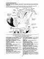
CHART
(_ Tie Rod Ball Joints
@ S_
Zerk
Spindle
Zerk
Front Wheel
Bearing zerk
Bearing zerk
Sector
Teeth
Engine
@ Mandrel
Zerks
(_Spray Silicone Lubricant (Move Boots to
Lubricate)
@General Purpose Grease
@Refer to Maintenance "ENGINE" Section
BEFORE EACH USE
1. Check engine oil level.
2. Check brake operation.
3. Check tire pressure.
4. Check operator presence and
interlock systems for proper operation.
5. Check for loose fasteners.
IMPORTANT:
Do not oil or grease the
pivot points which have special nylon
bearings. Viscous lubricants will attract
dust and dirt that will shorten the life of the
self-lubricating bearings. If you feel they
must be lubricated, use only a dry, powdered graphite type lubricant sparingly.
16
TRACTOR
Always observe safety rules when performing any maintenance.
IMPORTANT: To ensure proper assembly,
center hole in blade must align with star
on mandrel assembly.
4. Install and tighten blade bolt securely
(45-55 Ft. Lbs. torque).
IMPORTANT:
Special blade bolt is heat
treated.
BRAKE OPERATION
If tractor requires more than six (6) feet
stopping distance at high speed in highest
gear, then brake must be adjusted. (See
"TO ADJUST BRAKE" in the Service and
Adjustments section of this manual).
Assembly
TIRES
• Maintain proper air pressure in all tires
(See "PRODUCT SPECIFICATIONS"
section of this manual).
• Keep tires free of gasoline, oil, or insect
control chemicals which can harm rubber.
• Avoid stumps, stones, deep ruts, sharp
objects and other hazards that may
cause tire damage.
NOTE: To seal tire punctures and prevent
flat tires due to slow leaks, tire sealant
may be purchased from your local parts
dealer. Tire sealant also prevents tire dry
rot and corrosion.
Blade Bolt
Center Hol_
TO SHARPEN BLADE
NOTE: We do not recommend sharpening blade - but if you do, be sure the
blade is balanced.
Care should be taken to keep the blade
balanced. An unbalanced blade will cause
excessive vibration and eventual damage
to mower and engine.
• The blade can be sharpened with a file
or on a grinding wheel. Do not attempt
to sharpen while on the mower.
• To check blade balance, you will need a
5/8" diameter steel bolt, pin, or a cone
balancer. (When using a cone balancer,
follow the instructions supplied with
balancer.)
NOTE: Do not use a nail for balancing
blade. The lobes of the center hole may
appear to be centered, but are not.
• Slide blade on to an unthreaded portion
of the steel bolt or pin and hold the
bolt or pin parallel with the ground. If
blade is balanced, it should remain in a
horizontal position. If either end of the
blade moves downward, sharpen the
heavy end until the blade is balanced.
OPERATOR
PRESENCE
SYSTEM
Be sure operator presence and interlock
systems are working properly. If your tractor does not function as described, repair
the problem immediately.
• The engine should not start unless
the brake pedal is fully depressed and
attachment clutch control is in the disengaged position.
• When the engine is running, any attempt by the operator to leave the seat
without first setting the parking brake
should shut off the engine.
• When the engine is running and the
attachment clutch is engaged, any attempt by the operator to leave the seat
should shut off the engine.
• The attachment clutch should never operate unless the operator is in the seat.
5/8" Bolt
BLADE CARE
or
For best results mower blades must be kept
sharp. Replace bent or damaged blades.
Center Hole
BLADE REMOVAL
BATTERY
1. Raise mower to highest position to allow access to blades.
NOTE: Protect your hands with gloves
and/or wrap blade with heavy cloth.
2. Remove blade bolt by turning counterclockwise.
3. Install new or resharpened blade with
stamped "THIS SIDE UP" facing deck
and mandrel assembly.
Your tractor has a battery charging system
which is sufficient for normal use. However, periodic charging of the battery with
an automotive charger will extend its life.
• Keep battery and terminals clean.
• Keep battery bolts tight.
• Keep small vent holes open.
• Recharge at 6-10 amperes for 1 hour.
17
NOTE: The original equipment battery on
your tractor is maintenance free. Do not
attempt to open or remove caps or covers.
Adding or checking level of electrolyte is
not necessary.
TO CLEAN BATTERY AND TERMINALS
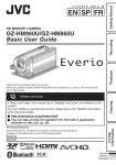
SAE VISCOSITY
3o
TEMPERATURE
Corrosion and dirt on the battery and
terminals can cause the battery to "leak"
power.
1. Remove terminal guard.
2. Disconnect BLACK battery cable first
then RED battery cable and remove
battery from tractor.
3. Rinse the battery with plain water and
dry.
4. Clean terminals and battery cable ends
with wire brush until bright.
5. Coat terminals with grease or petroleum jelly.
6. Reinstall battery (See"REPLACING
BATTERY" in the SERVICE AND ADJUSTMENTS section of this manual).
TO CHANGE
10
20
3o
40
BEFORE NEXT O_L CHANGE
o_ v_,c dla_t4 e
ENGINE OIL
Determine temperature range expected
before oil change. All oil must meet API
service classification SF-SJ.
• Be sure tractor is on level surface.
• Oil will drain more freely when warm.
• Catch oil in a suitable container.
1. Remove oil fill cap/dipstick. Be careful
not to allow dirt to enter the engine
when changing oil.
2. Remove yellow cap from end of drain
valve and install the drain tube onto the
fitting.
The transmission fan and cooling fins
should be kept clean to assure proper
cooling.
Do not attempt to clean fan or transmission while engine is running or while the
transmission is hot. To prevent possible
damage to seals, do not use high pressure
water or steam to clean transaxle.
• Inspect cooling fan to be sure fan blades
are intact and clean.
• Inspect cooling fins for dirt, grass clippings and other materials. To prevent
damage to seals, do not use compressed air or high pressure sprayer to
clean cooling fins.
PUMP
0
Change the oil after every 50 hours of operation or at least once a year if the tractor
is not used for 50 hours in one year.
Check the crankcase oil level before starting the engine and after each eight (8)
hours of operation.
TRANSAXLECOOLING
TRANSAXLE
qo
RANGE ANTICIPATED
GRADES
Oil Drain Valve
Yellow
Cap
_,
__-_ Closed and
Drain
Locked
Position
3. Unlock drain valve by pushing upward
slightly and turning counterclockwise.
4. To open, pull down on the drain valve.
5. After oil has drained completely, close
and lock the drain valve by pushing
upward and turning clockwise until the
pin is in the locked position as shown.
6. Remove the drain tube and replace the
cap onto the end of the drain valve.
7. Refill engine with oil through oil fill dipstick tube. Pour slowly. Do not overfill.
For approximate capacity see "PRODUCT SPECIFICATIONS" section of this
manual.
8. Use gauge on oil fill cap/dipstick for
checking level. Insert dipstick into
the tube and rest the oil fill cap on the
tube. Do not thread the cap onto the
tube when taking reading.
Keep oil
at "FULE' line on dipstick. Tighten cap
onto the tube securely when finished.
FLUID
The transaxle was sealed at the factory and
fluid maintenance is not required for the life
of the transaxle. Should the transaxle ever
leak or require servicing, contact a Sears or
other qualified service center.
V-BELTS
CheckV-belts for deterioration and wear after
100 hours of operation and replace if necessary. The belts are not adjustable. Replace
belts if they begin to slip from wear.
ENGINE
LUBRICATION
Only use high quality detergent oil rated with
API service classification SF-SJ. Select the
oil's SAE viscosity grade according to your
expected operating temperature.
18
ENGINE OIL FILTER
Replace the engine oil filter every season
or every other oil change if the tractor is
used more than 100 hours in one year.
CLEAN AIR INTAKE/COOLING AREAS
To insure proper cooling, make sure the
grass screen, cooling fins, and other external surfaces of the engine are kept clean
at all times.
Every 100 hours of operation (more often
under extremely dusty, dirty conditions),
remove the blower housing and other cooling shrouds. Clean the cooling fins and
external surfaces as necessary. Make sure
the cooling shrouds are reinstalled.
NOTE: Operating the engine with a blocked
grass screen, dirty or plugged cooling fins,
and/or cooling shrouds removed will cause
engine damage due to overheating.
AIR FILTER
Your engine will not run properly using a
dirty air filter. Clean the foam pre-cleaner
after every 25 hours of operation or every
season. Service paper cartridge every
100 hours of operation or every season,
whichever occurs first.
Service air cleaner more often under dusty
conditions.
1. Loosen knob and remove cover.
TO SERVICE PRE-CLEANER
2. Slide foam pre-cleaner off cartridge.
3. Wash it in liquid detergent and water.
4. Squeeze it dry in a clean cloth. Allow it
to dry.
5. Saturate it in engine oil. Wrap it in
clean, absorbent cloth and squeeze to
remove excess oil.
TO SERVICE
MUFFLER
Inspect and replace corroded muffler and
spark arrester (if equipped) as it could create a fire hazard and/or damage.
SPARK PLUG(S)
Replace spark plug(s) at the beginning
of each mowing season or after every
100 hours of operation, whichever occurs
first. Spark plug type and gap setting are
shown in "PRODUCT SPECIFICATIONS"
section of this manual.
CARTRIDGE
• Replace a dirty, bent, or damaged cartridge.
NOTE: Do not wash the paper cartridge
or use pressurized air, as this will damage
the cartridge.
1. Remove nut and cartridge plate.
2. Reinstall the pre-cleaner (cleaned and
oiled) over the paper cartridge.
3. Check rubber seal for damage and
proper position around stud. Replace
if necessary.
4. Reassemble air cleaner, cartridge
plate, and nut.
5. Reinstall air cleaner cover and secure
by tightening knob.
Foam
Pre-Cleaner
Cartridge
IN-LINE FUEL FILTER
The fuel filter should be replaced once
each season. If fuel filter becomes
clogged, obstructing fuel flow to carburetor, replacement is required.
1. With engine cool, remove filter and
plug fuel line sections.
2. Place new fuel filter in position in fuel
line with arrow pointing towards carburetor.
3. Be sure there are no fuel line leaks and
clamps are properly positioned.
4. Immediately wipe up any spilled gasoline.
Cartridge
Fuel
CLEANING
• Clean engine, battery, seat, finish, etc.
of all foreign matter.
• Keep finished surfaces and wheels free
of all gasoline, oil, etc.
• Protect painted surfaces with automotive type wax.
We do not recommend using a garden
hose or pressure washer to clean your
tractor unless the engine and transmission are covered to keep water out. Water
in engine or transmission will shorten the
useful life of your tractor. Use compressed
air or a leaf blower to remove grass,
leaves and trash from tractor and mower.
Rubber
Seat
Knob'
Nut
CLEAN AIR SCREEN
Air screen must be kept free of dirt and
chaff to prevent engine damage from
overheating. Clean with a wire brush or
compressed air to remove dirt and stubborn dried gum fibers.
19
WARNING:
TO AVOID SERIOUS INJURY, BEFORE PERFORMING
VICE OR ADJUSTMENTS:
1.
2.
3.
4.
5.
ANY SER-
Depress brake pedal fully and set parking brake.
Place attachment clutch in "DISENGAGED" position.
Turn ignition key to "STOP" and remove key.
Make sure the blades and all moving parts have completely stopped.
Disconnect spark plug wire from spark plug and place wire where it cannot
come in contact with plug.
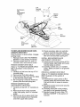
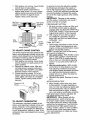
TO INSTALL MOWER
Be sure tractor is on level surface and
mower suspension arms are raised with
attachment lift control. Engage parking
brake.
1. Swing anti-sway bar to left side of
mower deck.
2. Slide mower under tractor with deflector shield to right side of tractor.
IMPORTANT: Check belt for proper routing in all mower pulley grooves.
3. If equipped, turn height adjustment
knob counterclockwise until it stops.
4. Lower mower linkage with attachment
lift control.
5. Be sure belt tension rod is in disengaged position.
6. Install belt into electric clutch pulley
g reeve.
7. Place the suspension arms on outward
pointing deck pins. Retain with double
loop retainer spring with loops up as
shown.
8. Install front plate assembly to tractor
suspension brackets and retain with
single loop retainer springs as shown.
TRACTOR
TO REMOVE MOWER
1. Place attachment clutch in "DISENGAGED" position.
2. If equipped, turn height adjustment
knob to lowest setting.
3. Lower mower to its lowest position.
4. Disengage belt tension rod from lock
bracket.
_CAUTION:
Rod is spring loaded. Have
a tight grip on rod and release slowly.
5. Remove retainer spring holding
anti-swaybar to chassis bracket and
disengage anti-sway bar from bracket.
6. Remove four retainer springs from front
plate assembly and remove plate.
7. Remove retainer springs from suspension arms at deck and disengage arms
from deck.
8. Raise attachment lift to its highest position.
9. Slide mower forward and remove belt
from electric clutch pulley.
10.Slide mower out from under right side
of tractor.
Belt Tension
Rod
(Disengaged _/,
Position)
/,
Lock Bracket
Front Mower
Bracket
Electric Clutch
Double Loop
Retainer Springs
Front Plate
Chassis
Bracket
Single Loop
Retainer Springs
Retainer
Spring
Flanged Pins
Anti-Sway
Bar
Bracket
USE PLIERS FOR
:{ETAINER SPRINGS
Suspension Arms
Double Loop
Retainer Springs
(Outward pointing
deck pins)
\
Deflector Shield
20
9. Position front plate assembly between
front mower brackets. Raise deck and
plate assembly to align holes and
insert flanged pins. Secure pins with
double loop retainer springs between
the plate assembly and mower brackets.
NOTE: To assist in locating hole in flanged
pin, the hole in pin is inline with notch on
head of pin. If necessary, move mower
side-to-side to give space between plate
and mower brackets.
IMPORTANT: Check belt for proper routing in all mower pulley grooves.
10. Engage belt tension rod by pushing rod
into locking bracket.
_,CAUTION:
Belt tension rod is spring
loaded. Have a tight grip on rod and engage slowly.
11. Connect anti-sway bar to chassis
bracket under left footrest and retain
with double loop retainer spring.
12. If equipped, turn height adjustment
knob clockwise to remove slack from
mower suspension.
13. Raise deck to highest position.
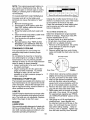
TO LEVEL MOWER HOUSING
Adjust the mower while tractor is parked
on level ground such as a carport or garage. Make sure tires are properly inflated
(See "PRODUCT SPECIFICATIONS"
section of this manual). If tires are over or
underinflated, you will not properly adjust
your mower.
SIDE-TO-SIDE ADJUSTMENT WITH
BUBBLE LEVEL
NOTE: If necessary, check side-to-side
surface below tractor for levelness with a
long board and the bubble level.
• Using the lift lever, place mower in
position where no part of the mower,
including gauge wheels, is touching the
ground.
• From left side of tractor, find the level
decal on top of mower and place bubble
level on decal as indicated.
• Mower is level side-to-side when bubble
is between the two lines in the bubble
level.
• If adjustment is necessary, under left
hand footrest, turn lift link adjustment
nut (above yellow cap) in appropriate
direction to bring bubble between the
lines in the bubble level.
• Remove bubble level from mower and
store in a safe place.
Bubble Between
Level Decal
Brake
.-_
Left Hand Footrest
Pedal/"
Yellow Cap
ALTERNATE SIDE-TO-SIDE
ADJUSTMENT METHOD
• Raise mower to its highest position.
• Measure height from bottom edge of
mower to ground level at front corners
of mower. Distance "A" on both sides of
mower should be the same.
• If adjustment is necessary, make adjustment on one side of mower only.
• To raise one side of mower, tighten lift
link adjustment nut on that side.
• To lower one side of mower, loosen lift
link adjustment nut on that side.
NOTE:
Each full turn of adjustment nut
will change mower height about 3/16".
• Recheck measurements after adjusting.
Bottom Edge of
Mower to Ground
(_
Bottom Edge of
Mower to Ground
Suspension
Lift Li_
Adjustment Nut
FRONT-TO-BACK ADJUSTMENT
IMPORTANT:
Deck must be level sideto-side. If the following front-to-back
adjustment is necessary, be sure to adjust
both front links equally so mower will stay
level side-to-side.
To obtain the best cutting results, the
mower blades should be adjusted so the
front tip is approximately 1/8" to 1/2" lower
than the rear tip when the mower is in its
21 highest position.
TO REPLACE MOWER DRIVE BELT
/I, CAUTION: Blades are sharp. Protect
your hands with gloves and/or wrap blade
with heavy cloth.
Check adjustment on right side of tractor.
Position any blade so the tip is pointing
straight forward. Measure distance "B" at
front and rear tip of blade
• Before making any necessary adjustments, check that both front plate links
are equal in length.
• If links are not equal in length, adjust
one link to same length as other link.
• To lower front of blade, loosen nut "C"
on both front links an equal number of
turns.
NOTE: Each full turn of nut "C" will
change dim. "B" by approximately 3/16".
• When distance "B" is 1/8" to 1/2" lower
at front than rear, tighten nut "D" against
trunnion on both front links.
• To raise front of blade, loosen nut
"D" from trunnion on both front links.
Tighten nut "C" on both front links an
equal number of turns. The two front
links must remain equal in length.
• When distance "B" is 1/8" to 1/2" lower
at front than rear, tighten nut "D" against
trunnion on both front links.
• Recheck side-to-side adjustment.
MOWER DRIVE BELT REMOVAL
1. Park tractor on a level surface. Engage
parking brake.
2. Lower mower to its lowest position.
3. Disengage belt tension rod from lock
bracket.
_CAUTION:
Rod is spring loaded. Have
a firm grip on rod and release slowly.
4. Remove screws from R.H. mandrel
cover and remove cover.
5. Remove any dirt or grass clippings
which may have accumulated around
mandrels and entire upper deck surface.
6. Disconnect R.H. suspension arm from
rear deck bracket by removing retainer
spring.
7. Carefully roll belt over the top of R.H.
mandrel pulley.
8. Remove belt from electric clutch pulley.
9. Remove belt from idler pulleys.
10.Check primary idler arm and two idlers
to see that they rotate freely.
11. Be sure spring is securely hooked to
primary idler arm and spring arm.
MOWER DRIVE BELT INSTALLATION
12. Install belt in both idlers.
13. Install new belt onto electric clutch pulley.
14. Carefully roll belt into upper groove of
R.H. mandrel pulley.
15. Carefully check belt routing making
sure belt is in the grooves correctly.
16. Reconnect R.H. suspension arm to
rear deck bracket with retainer spring.
17. Reassemble R.H. mandrel cover.
18. Engage belt tension rod by pushing
rod into locking bracket.
BOTH FRONT PLATE LINKS MUST BE
EQUAL IN LENGTH
Front Plate
Assembly
Trunnion
22
a.H.
Mandrel
Belt Tension
Rod
Cover
(Disengaged
Electric
Position)
Pulley
Idler
Pulleys
a.H.
Mandrel
Arm
Suspension
Arm
Primary
Idler Arm
TO REPLACE MOWER BLADE (SECONDARY) DRIVE BELT
Park the tractor on level surface. Engage
parking brake.
1. Remove mower (See "TO REMOVE
MOWER" in this section of manual).
2. Remove screws from R.H. and L.H.
mandrel covers and remove covers.
10. Check secondary idler arm and idler
pulley to see that they rotate freely.
11. Be sure spring is hooked in secondary
idler arm and secondary spring arm.
INSTALL NEW MOWER BLADE
(SECONDARY) DRIVE BELT
12. Install new belt in lower groove of R.H.
mandrel pulley, idler pulley, and center
mandrel pulley as shown.
13.Carefully roll belt over L.H. mandrel
pulley. Make sure belt is in all grooves
properly.
REINSTALL MOWER DRIVE BELT
REMOVE MOWER DRIVE BELT
(Refer to "TO REMOVE MOWER DRIVE
BELT" illustration in this section of
manual).
3. Carefully roll belt over the top of R.H.
mandrel pulley.
4. Remove belt from idler pulleys.
5. Check primary idler arm and two idlers
to see that they rotate freely.
6. Be sure spring is securely hooked to
primary idler arm and spring arm.
(Refer to "TO REMOVE MOWER DRIVE
BELT" illustration in this section of
manual).
14. Install belt into upper groove of R.H.
mandrel pulley and around both idlers.
Pull belt to front of mower to remove
slack.
15. Reinstall mandrel covers and securely
tighten all screws.
16. Carefully check belt routing making
sure belt is in all grooves correctly.
17. Reinstall mower to tractor (See "TO
INSTALL MOWER" in this section of
manual).
REMOVE MOWER BLADE
(SECONDARY) DRIVE BELT
7. Carefully roll belt off L.H. mandrel pulley.
8. Remove belt from center mandrel
pulley, idler pulley, and R.H. mandrel
pulley.
9. Remove any dirt or grass which may
have accumulated around mandrels
and entire upper deck surface.
23
L.H.
Secondary
Idler Arm
Idler
ring
Secondary
Arm
Mandrel
Mower Blade
(Secondary)
Drive Belt
R.H.
Mandrel
TO ADJUST ATTACHMENT
CLUTCH
The electric clutch should provide years
of service. The clutch has a built-in brake
that stops the pulley within 5 seconds.
Eventually, the internal brake will wear
which may cause the mower blades to
not engage, or, to not stop as required.
Adjustments should be made by a Sears
or other qualified service center.
1. Make sure attachment clutch and ignition switches are in "OFF" position.
2. Adjust the three nylon Iocknuts until
space between clutch plate and rotor
measures .012"at all three slot locations cut in the side of brake plate.
NOTE: After installing a new electric
clutch, run tractor at full throttle and
engage and disengage electric clutch 10
cycles to wear in clutch plate.
Rotor-_---___
Clutch Plate ',
Slot (3)
m01
2"
Brake
Plate
Nylon Locknut (3)
TO CHECK AND ADJUST BRAKE
If tractor requires more than five (5) feet to
stop at highest speed in highest gear on a
level, dry concrete or paved surface, then
brake must be checked and adjusted.
2. Disengage transmission by placing
freewheel control in "transmission disengaged" position. Pull freewheel control out and into the slot and release so
it is held in the disengaged position.
The rear wheels must lock and skid when
you try to manually push the tractor forward. If the rear wheels rotate, the brake
needs to be adjusted or the pads need to
be replaced.
TO ADJUST BRAKE
Contact a Sears or other qualified service
center.
TO REPLACE MOTION DRIVE BELT
Park the tractor on level surface. Engage
parking brake. For ease of service there is
a belt installation guide decal on bottom of
left footrest.
1. Remove mower (See "TO REMOVE
MOWER" in this section of this manual.)
BELT REMOVAL 2. Create slack in belt by removing
retainer spring from drive belt tension
handle.
3. Remove belt from all idler pulleys,
transaxle pulley and then from engine
pulley.
BELT INSTALLATION
-
1. Install new belt around engine pulley
first, then around transaxle pulley and
lastly into all the idler pulleys.
TO CHECK BRAKE
2.
Check to be sure belt is positioned cor1. Park tractor on a level, dry concrete or
rectly and is on proper side of all belt
paved surface, depress clutch/brake
keepers.
pedal all the way down and engage
3.
Engage the drive belt tension handle
parking brake.
and replace the retainer spring.
244. Reinstall mower.
FRONT WHEEL TOE-IN/CAMBER
The front wheel toe-in and camber are not
adjustable on your tractor. If damage has
occurred to affect the front wheel toe-in or
camber, contact a Sears or other qualified
service center.
Retainer
Spring
Driv(
Tension
Handle
TO REMOVE
Engine Pulley
V-Idler
Keeper
Clutching
Idler
FOR REPAIRS
FRONT WHEEL 1. Block up axle securely.
2. Remove axle cover, retaining ring and
washers to allow wheel removal.
3. Repair tire and reassemble.
4. Replace washers and snap retaining
ring securely in axle groove.
5. Replace axle cover.
Transaxle Pulley
Belt
Keeper
WHEEL
Belt
Keeper
Clutching
Flat Idler
REAR WHEEL
-
1. Block rear axle securely.
2. Remove five (5) hub bolts to allow
wheel removal.
3. Repair tire and reassemble. Replace
and tighten hub bolts securely.
NOTE: To seal tire punctures and prevent
flat tires due to slow leaks, purchase and
use tire sealant from Sears. Tire sealant
also prevents tire dry rot and corrosion.
TRANSAXLE
MOTION CONTROL LEVER NEUTRAL ADJUSTMENT
The motion control lever has been preset
at the factory and adjustment should not
be necessary.
1. Park Tractor on level surface. Stop
tractor by turning ignition key to "OFF"
position and engage parking brake.
2. Loosen the adjustment bolt in front of
the right rear wheel.
3. Move motion control lever to the neutral position.
4. Tighten the adjustment bolt.
R
etaining
Ring
\
Axle \
Washers
r_
/\
_'_,
/ \ IIt
(f_4 IlI
Adjustment Bolt
O0663
TO START ENGINE WITH A WEAK BATTERY
_L,WARNING: Lead-acid batteries generate explosive gases. Keep sparks, flame
and smoking materials away from batteries. Always wear eye protection when
around batteries.
If your battery is too weak to start the
engine, it should be recharged. (See "BATTERY" in the MAINTENANCE section of
this manual).
If "jumper cables" are used for emergency
starting, follow this procedure:
IMPORTANT: Your tractor is equipped
with a 12 volt system. The other vehicle
must also be a 12 volt system. Do not use
your tractor battery to start other vehicles.
TRANSMISSION REMOVAL/
REPLACEMENT
Should your transmission require removal
for service or replacement, it should be
purged after reinstallation and before operating the tractor. See "PURGE TRANSMISSION" in the Operation section of this
manual.
TO ADJUST
MENT
If steering
horizontal
positioned
ing wheel
horizontal.
STEERING
WHEEL
ALIGN-
wheel crossbars are not
(left to right) when wheels are
straight forward, remove steerand reassemble with crossbars
Tighten securely.
TO ATTACH JUMPER CABLES 1. Connect one end of the RED cable
to the POSITIVE (+) terminal of each
battery(A-B), taking care not to short
against tractor chassis.
25
2. Connect one end of the BLACK cable
to the NEGATIVE (-) terminal (C) of
fully charged battery.
3. Connect the other end of the BLACK
cable (D) to good chassis ground,
away from fuel tank and battery.
TO REMOVE
ORDER -
CABLES,
REVERSE
1.
BLACK
cable first from chassis
2.
then from the fully charged battery.
RED cable last from both batteries.
Weak or Dead
Battery
and
Fully Charged
Battery
REPLACING
BATTERY
_WARNING:
Do not short battery
terminals by allowing a wrench or any
other object to contact both terminals at
the same time. Before connecting battery,
remove metal bracelets, wristwatch bands,
rings, etc.
Positive terminal must be connected
first to prevent sparking from accidental
grounding.
1. Lift hood to raised position.
2. Remove terminal guard.
3. Disconnect BLACK battery cable
then RED battery cable and carefully
remove battery from tractor.
4. Install new battery with terminals in
same position as old battery.
5. Reinstall terminal guard.
6. First connect RED battery cable to
positive (+) battery terminal with hex
bolt and keps nut as shown. Tighten
securely.
7. Connect BLACK grounding cable to
negative (-) battery terminal with remaining hex bolt and keps nut. Tighten
securely
8. Close terminal access doors.
9. Close hood.
Terminal
Access
Termin_
TO REPLACE HEADLIGHT
LAMP
a_m CAUTION: When lit, the halogen
ps get extremely hot. Hold lamp assembly by the holder and do not touch the
bulb.
1. Raise hood.
2. Disconnect harness from lamp assembly.
3. Rotate counterclockwise and pull lamp
assembly out of the hole in the backside of the grill.
4. Insert new lamp assembly and rotate
clockwise to lock.
5. Reconnect harness to lamp
assembly.
6. Close hood.
INTERLOCKS
AND RELAYS
Loose or damaged wiring may
your tractor to run poorly, stop
prevent it from starting.
• Check wiring. See electrical
diagram in the Repair Parts
TO REPLACE FUSE
cause
running, or
wiring
section.
Replace with 30 amp automotive-type
plug-in fuse. The fuse holder is located
behind the dash.
TO REMOVE HOOD AND GRILL ASSEMBLY
1. Raise hood.
2. Unsnap headlight wire connector.
3. Stand in front of tractor. Grasp hood at
sides, tilt toward engine and lift off of
tractor.
4. When replacing hood, be sure to reconnect the headlight wire connector.
_"__
_
X_
iOH:adlig ht wire
Connector
ENGINE
Maintenance, repair, or replacement of
the emission control devices and systems,
which are being done at the customers expense, may be performed by any non-road
KepsNut
,....-_-...._ Hex Bolt
...;., .. -___"::>.._.f _
"_
engine repair establishment or individual.
Warranty repairs must be performed by an
authorized engine manufacturer's service
( __"/_
Positive
outlet.
(Red) Cable
TO ADJUSTTHROTTLE
CONTROL
CABLE
The throttle control has been preset at the
"i_L - _/
_Negative (Black)
L,_ _
Cable
factory and adjustment should not be necessary. Check adjustment as described
below before loosening cable. If adjust26ment is necessary, proceed as follows:
With enginenot running, movethrottle
controlleverto fast position.
2. Checkthat speed control leveris
againststop screw.If it is not, loosen
casing clampscrew and pull throttle
cable until leveris against screw.
Tighten clampscrew securely.
Idle
Adjusting
Needle
Adjusting
Screw
Throttle
Control
Cable
Stop
Screw
Choke
Control
Clamp Screw
TO ADJUST CHOKE CONTROL
The choke control has been preset at the
factory and adjustment should not be necessary, check adjustment as described below before loosening cable. If adjustment
is necessary, proceed as follows:
1. With engine not running, move choke
control (located on dash panel) to full
choke position.
2. Remove air cleaner cover, filter and
cartridge plate to expose carburetor
choke (See "AIR FILTER" in the Maintenance section of this manual).
3. Choke should be closed. If it is not,
loosen casing clamp screw and move
choke cable until choke is completely
closed. Tighten casing clamp screw
securely.
Closed for Full
In general, turning the adjusting needles
in (clockwise) decreases the supply of
fuel to the engine giving a leaner fuel/air
mixture. Turning the adjusting needles out
(counterclockwise)
increases the supply
of fuel to the engine giving a richer fuel/air
mixtu re.
IMPORTANT:
Damage to the needles
and the seats in carburetor may result if
screw is turned in too tight.
PRELIMINARY SETTING 1. Be sure you have a clean air filter, and
the throttle control cable is adjusted
properly (see "TO ADJUST THROTTLE
CONTROL CABLE" in the Service and
Adjustments section of this manual).
2. With engine off turn idle fuel adjusting needle in (clockwise) closing it
finger tight and then turn out (counterclockwise) 1 turn.
FINAL SETTING 1. Start engine and allow to warm for five
minutes. Make final adjustments with
engine running and shift/motion control
lever in neutral (N) position.
NOTE: The high idle is set at the factory
and cannot be adjusted.
2. Idle speed setting - With throttle control
lever in slow position, engine should
idle at 1200 RPM If engine idles too
slow or fast, turn idle speed adjusting
screw in or out until correct idle is attained.
3. Idle fuel needle setting - With throttle
control lever in slow position, turn idle
fuel adjusting needle in (clockwise)
until engine speed decreases and then
turn out (counterclockwise) approximately 3/4 turn to obtain the best low
speed performance.
4. Recheck idle speed. Readjust if necessary.
ACCELERATION TEST 5. Move throttle control lever from slow
to fast position. If engine hesitates or
dies, turn idle fuel adjusting needle out
(counterclockwise)
1/8 turn. Repeat
test and continue to adjust, if necessary, until engine accelerates smoothly.
High speed stop is factory adjusted. Do
not adjust-damage may result.
IMPORTANT: Never tamper with the
engine governor, which is factory set
for proper engine speed. Overspeeding
the engine above the factory high speed
setting can be dangerous. If you think the
engine-governed high speed needs adjusting, contact a Sears or other qualified
service center, which has proper equipment and experience to make any neces-
TO ADJUST CARBURETOR
The carburetor has been present at the
factory and adjustment should not be necessary. However, minor adjustment may
be required to compensate for differences
in fuel, temperature, altitude or load. If the
carburetor does need adjustment, proceed
as follows:
27sary adjustments.
Immediatelyprepareyour tractorfor storage at the end of the season or if the tractor will not be usedfor 30 daysor more.
_WARNING: Neverstore the tractor
with gasoline in the tank insidea building
where fumes may reachan open flame
or spark. Allow the engineto cool before
storing in any enclosure.
blended fuels (called gasohol or using
ethanol or methanol) can attract moisture
which leads to separation and formation of
acids during storage. Acidic gas can damage the fuel system of an engine while in
storage.
1. Drain the fuel tank.
2. Start the engine and let it run until the
fuel lines and carburetor are empty.
• Never use engine or carburetor cleaner
products in the fuel tank or permanent
damage may occur.
• Use fresh fuel next season.
NOTE: Fuel stabilizer is an acceptable
alternative in minimizing the formation of
fuel gum deposits during storage. Add
stabilizer to gasoline in fuel tank or storage container. Always follow the mix ratio
found on stabilizer container. Run engine
at least 10 minutes after adding stabilizer
to allow the stabilizer to reach the carburetor. Do not drain the gas tank and
carburetor if using fuel stabilizer.
ENGINE OIL
TRACTOR
Remove mower from tractor for winter
storage. When mower is to be stored for a
period of time, clean it thoroughly, remove
all dirt, grease, leaves, etc. Store in a
clean, dry area.
1. Clean entire tractor (See"CLEANING"
in the Maintenance section of this
manual).
2. Inspect and replace belts, if necessary
(See belt replacement instructions in
the Service and Adjustments section of
this manual).
3. Lubricate as shown in the Maintenance
section of this manual.
4. Be sure that all nuts, bolts and screws
are securely fastened. Inspect moving
parts for damage, breakage and wear.
Replace if necessary.
5. Touch up all rusted or chipped paint
surfaces; sand lightly before painting.
Drain oil (with engine warm) and replace
with clean engine oil. (See "ENGINE" in
the Maintenance section of this manual).
CYLINDER(S)
1. Remove spark plug(s).
2. Pour one ounce of oil through spark
plug hole(s) into cylinder(s).
3. Turn ignition key to "START" position
for a few seconds to distribute oil.
4. Replace with new spark plug(s).
BATTERY
• Fully charge the battery for storage.
• After a period of time in storage, battery
may require recharging.
• To help prevent corrosion and power
leakage during long periods of storage,
battery cables should be disconnected
and battery cleaned thoroughly (see "TO
CLEAN BATTERY AND TERMINALS" in
the Maintenance section of this manual).
• After cleaning, leave cables disconnected and place cables where they
cannot come in contact with battery
terminals.
• If battery is removed from tractor for
storage, do not store battery directly on
concrete or damp surfaces.
OTHER
• Do not store gasoline from one season
to another.
• Replace your gasoline can if your can
starts to rust. Rust and/or dirt in your
gasoline will cause problems.
• If possible, store your tractor indoors
and cover it to give protection from dust
and dirt.
• Cover your tractor with a suitable protective cover that does not retain moisture. Do not use plastic. Plastic cannot
breathe which allows condensation to
form and will cause your tractor to rust.
IMPORTANT:
Never cover tractor while
engine and exhaust areas are still warm.
ENGINE
FUEL SYSTEM
IMPORTANT: It is important to prevent
gum deposites from forming in essential
fuel system parts such as carburetor, fuel
hose, or tank during storage. Also, alcohol
28
TROUBLESHOOTING
CHART:
See appropriate section in manual unless directed to Sears service center
PROBLEM
Will not start
CAUSE
CORRECTION
1. Out of fuel.
2. Engine not "CHOKED"
properly.
3. Engine flooded.
4.
5.
6.
7.
Bad spark plug.
Dirty air filter.
Dirty fuel filter.
Water in fuel.
8. Loose or damaged wiring.
9. Carburetor out of adjustment.
10. Engine valves out of
adjustment.
11. Extreme Cold Conditions
Hard to start
1.
2.
3.
4.
5.
Dirty air filter.
Bad spark plug.
Weak or dead battery.
Dirty fuel filter.
Stale or dirty fuel.
6. Loose or damaged wiring.
7. Carburetor out of adjustment.
8. Engine valves out of
adjustment.
Engine will not
turn over
1. Brake pedal not
depressed
2. Attachment clutch is
engaged.
3. Weak or dead battery.
4. Blown fuse.
5. Corroded battery terminals.
6. Loose or damaged wiring.
7. Faulty ignition switch.
1.
2.
3.
4.
5.
Clean/replace air filter.
Replace spark plug.
Recharge or replace battery.
Replace fuel filter.
Drain fuel tank and refill with
fresh gasoline.
6. Check all wiring.
7. See "To Adjust Carburetor" in
Service and Adjustments
section.
8. Contact a Sears or other
qualified service center.
1. Depress brake pedal.
9. Faulty operator presence
switch(es).
2. Disengage attachment
clutch.
3. Recharge or replace battery.
4. Replace fuse.
5. Clean battery terminals.
6. Check all wiring.
7. Check/replace ignition
switch.
8. Check/replace solenoid or
starter.
9. Contact a Sears or other
qualified service center.
1.
2.
3.
4.
1.
2.
3.
4.
8. Faulty solenoid or starter.
i Engine clicks but
will not start
1. Fill fuel tank.
2. See "TO START ENGINE"
in Operation section.
3. Wait several minutes before
attempting to start.
4. Replace spark plug.
5. Clean/replace air filter.
6. Replace fuel filter.
7. Drain fuel tank and carburetor, refill tank with fresh
gasoline and replace fuel
filter.
8. Check all wiring.
9. See "To Adjust Carburetor"
in Service and Adjustments
section.
10.Contact a Sears or other
qualified service center.
11. See "To start engine" in
operation section.
Weak or dead battery.
Corroded battery terminals.
Loose or damaged wiring.
Faulty solenoid or starter.
29
Recharge or replace battery.
Clean battery terminals.
Check all wiring.
Check/replace solenoid or
starter.
TROUBLESHOOTING
CHART:
See appropriate section in manual unless directed to Sears service center
PROBLEM
CAUSE
Lossofpower
•
2.
3.
4.
5.
6.
CORRECTION
Cutting too much grass/too
fast.
Throttle in "CHOKE"
position•
Build-up of grass, leaves
and trash under mower.
Dirty air filter•
Low oil level/dirty oil.
Faulty spark plug.
7. Dirty fuel filter•
8. Stale or dirty fuel.
9.
Water in fuel.
10. Spark plug wire loose.
11. Dirty engine air screen/fins.
12. Dirty/clogged muffler.
13. Loose or damaged wiring•
14. Carburetor out of
adjustment.
15. Engine valves out of
adjustment.
Excessive
vibration
1. Worn, bent or loose blade•
2.
Bent blade
mandrel.
3. Loose/damaged
Engine continues
to run when
operator leaves
seat with
attach ment
clutch engaged
Poor cut - uneven
part(s).
1. Faulty operator-safety
presence control system•
•
Worn, bent or loose blade•
2. Mower deck not level•
3. Buildup of grass, leaves,
and trash under mower.
4. Bent blade mandrel.
5. Clogged mower deck vent
from build-up of grass,
leaves, and trash around
mandrels.
30
1. Set in "Higher Cut" position/
reduce speed.
2. Adjust throttle control•
3. Clean underside of mower
housing.
_. Clean/replace air filter•
5. Check oil level/change oil.
3. Clean and regap or change
spark plug.
7. Replace fuel filter•
3. Drain fuel tank and refill
with fresh gasoline.
_). Drain fuel tank and
carburetor, refill tank with
fresh gasoline and replace
fuel filter•
10. Connect and tighten spark
plug wire.
11. Clean engine air screen/
fins.
12. Clean/replace muffler•
13.Check all wiring.
14. See "To Adjust Carburetor"
in Service and Adjustments
section•
15.Contact a Sears or other
qualified service center•
• Replace
Tighten
2. Contact
qualified
3. Tighten
Replace
blade•
blade bolt.
a Sears or other
service center•
loose part(s).
damaged parts•
Check wiring, switches and
connections. If not corrected
contact a Sears or other
qualified service center•
• Replace blade• Tighten
blade bolt.
2. Level mower deck.
3. Clean underside of mower
housing.
_. Contact a Sears or other
qualified service center•
5. Clean around mandrels to
open vent holes•
TROUBLESHOOTING
CHART:
See appropriate section in manual unless directed to Sears service center
PROBLEM
i Mower blades will
not rotate
Poor grass
discharge
CAUSE
CORRECTION
1. Obstruction in clutch
mechanism.
2. Worn/damaged mower
drive belt.
3. Frozen idler pulley.
4. Frozen blade mandrel.
1. Engine speed too slow.
2. Travel speed too fast.
3. Wet grass.
4. Mower deck not level.
5. Low/uneven tire air pressure.
8. Worn, bent or loose blade.
7. Buildup of grass, leaves and
trash under mower.
8. Mower drive belt worn.
9. Blades improperly installed.
10. Improper blades used.
11. Clogged mower deck vent
holes from buildup of
grass, leaves, and trash
around mandrels.
1. Remove obstruction.
2. Replace mower drive belt.
3. Replace idler pulley.
4. Contact a Sears or other
qualified service center.
1. Place throttle control in
"FAST" position.
2. Shift to slower speed.
3. Allow grass to dry before
mowing.
4. Level mower deck.
5. Check tires for proper air
pressure.
6. Replace/sharpen blade.
Tighten blade bolt.
7. Clean underside of mower
housing.
8. Replace mower drive belt.
9. Reinstall blades sharp edge
down.
10. Replace with blades listed
in this manual.
11. Clean around mandrels to
open vent holes.
Switch is "OFF".
1. Turn switch "ON".
Bulb(s) or lamp(s) burned out. 2. Replace bulb(s) or lamp(s).
Faulty light switch.
3. Check/replace light switch.
Loose or damaged wiring.
4. Check wiring and connections.
5. Blown fuse.
5. Replace fuse.
i Headlight(s) not
working
(if so equipped)
1.
2.
3.
4.
Battery will not
charge
1. Bad battery cell(s).
2. Poor cable connections.
3. Faulty regulator
1. Replace battery.
2. Check/clean all connections.
3. Replace regulator.
(if so equipped).
Loss of drive
Engine "backfires"
when turning
engine
"OFF"
4. Faulty alternator.
4. Replace alternator.
1. Freewheel control in
"disengaged" position.
2. Motion drive belt worn,
damaged, or broken.
3. Air trapped in transmission
during shipment or servicing.
1. Place freewheel control in
"engaged" position.
2. Replace motion drive belt.
1. Engine throttle control not
set at "SLOW"
position for 30 seconds
before stopping engine.
31
3. Purge transmission.
.
Move throttle control to
"SLOW" position and allow
to idle for 30 seconds before
stopping engine.
32
TRACTOR
-- MODEL
NUMBER
917.275285
SCHEMATIC
BATTERY
SOLENOID
RED
RED
_L
FUSE
STARTER
i
_)AMMETER
BLACK
Gi
WHITE
I
J
_RED
ELECTRIC
CLUTCH
I
I
CLUTCH
/ BRAKE
(PEDAL
i:
I
j
UP)
R£D
SEAT SWITCH
(NOT OCCUPIED)
DI
PTO (DISENGAGED)
BLACK
GROUNDING
CONNECTOR
_/F
SPARK PLUGS
UN,TONTWINC
ENG,NES,
L.
I
FUEL
CHARGING _YSTEM OUTPUT
15 AMP DC @ 3600 RpM
SHUT-OFF
SOLENOID
TACHOMETER
j_
28 VOLTS AC @ 3600 RPM
(REGULATOR DIECONNECTE£
_A
R_
L_ E_m_OJR_jj
REGULATOR
'
PTO SWITCH
POSITION
IGNITION SWITCH
POSITION
CIRCUIT
C+G,B+H
C+F,B+E,A+D
_MAKE _'
OFF
M+G+A1
NONE
ON + LIGHT_
B+A1
L+A2
ON
E+A1
NONE
B+S+A1
NONE
START
OFF
ON
HEADLIGHTS
CIRCUIT
WIRING INSULATED CLIPS
NOTE: IF WIRING INSULATED
CLIPS WERE REMOVED FOR
SERVICING OF UNIT, THEY
SHOULD BE REPLACED TO
PROPERLY SECURE YOUR
WIRING.
•
REMOVABLE
CONNECTIONS
NON-REMOVABLE
CONNECTIONS
GFC
H
N
DA
33
B
TRACTOR
-- MODEL
NUMBER
917.275285
ELECTRICAL
/
/
79
J
/
I
I
I
I
/
I
I
I
I
I
I
33
11
I
I
29
8
12
I
I
I
34
TRACTOR
-- MODEL
NUMBER
917.275285
ELECTRICAL
KEY
NO.
1
2
8
10
11
12
16
21
25
26
27
28
29
30
33
40
42
45
46
50
79
81
91
PART
NO.
144927
74760412
7603J
145211
150109
145769
176138
175449
185456
108824X
73510400
170697
121305X
175442
175447
188033
154336
177500
177501
178461
175448
109748X
184932
DESCRIPTION
Battery
Bolt Hex Head 1/4-20 x 3/4
Tray, Battery
Belt 1/4-20 x 7.5 Zinc
Hold down Battery Dash Mount
Nut Push Nylon 1/4"
Switch Interlock
Harness Socket Light Halogen
Cable 4 Ga. 31" Red CV25 w/16.W.
Fuse
Nut, Keps Hex 1/4-20 Unc
Cable, Ground
Switch, Plunger
Switch, lgn
Key, Ignition
Harness lgn.
Cover Terminal
Ammeter
Meter, Hour
Switch, PTO
Bulb and Holder Asm. Halogen
Relay Asm.
Tachometer Round
NOTE: All component dimensions given in U. S.
inches 1 inch = 25.4 mm
35
TRACTOR
CHASSIS AND ENCLOSURES
-- MODEL
NUMBER
917.275285
161
158
37
J
31
162_
35
122
130
150
122
156
_7
159
_152
_156
43_
139_
28
21
\
32_,
_17
3_139
17
\
i
i
56
45
\_
19
20
99
\
86
chassis-steatth39-vg
36
TRACTOR
CHASSIS AND ENCLOSURES
-- MODEL
NUMBER
917.275285
KEY
NO.
PART
NO.
DESCRIPTION
1
2
5
6
7
8
14
15
16
17
18
19
20
21
24
25
28
30
31
32
33
34
35
36
37
39
43
44
45
47
50
56
58
68
86
91
99
122
130
138
139
142
144
148
150
152
153
156
158
159
161
162
165
166
180375
175282
180639X418
157882
17720408
184668
175260X615
161841
121794X
17000612
174515X615
19131312
STD523710
STD541437
179717X615
161842
179716X615
145052
161419
161327
161326
177018
19111116
17060512
178510X615
175278
136939
136940
176018
17490608
175476
176016
183569
17490508
74780716
180374
177143
161464
171875
179125X418
171873
161897
161900
164655
175352
177956
181574
17000512
17670608
17000612
179612X418
142432
183554
73680700
Kit Rail Chass. RH GT Serv.
Drawbar, Gt
Dash
Dash, Lower Vgt One Piece
Screw, Thd Cut 1/4-20 x 1/2
Support, Battery
Hood Asm
Lens LH
Cover, Access
Screw 3/8-16 x .75
Grille
Washer 13/32 x 13/16 x 12 Ga.
Bolt, FinHex 3/8-16xl
NutCrownlock
3/8-16Unc
Footrest, RH
Lens RH
Footrest, LH
Saddle, Hydro
Brace, Supt 1-pc VGT
Bracket, Pivot Chassis Lh
Bracket, Pivot Chassis Rh
Plate Asm Engine
Washer 11/32x11/16x16Ga.
Screw 5/16-18 x 3/4
Fender Pnt
Bracket, Axle Front
Bracket, Spnsn Front Lh
Bracket, Spnsn Front Rh
Bracket Asm., Susp Chas.Rh
Screw ThdroL 3/8-16 x 1/2
Bracket, Chassis Front
Bracket Asm., Susp Chas. Lh
Bracket Asm., Fender
Screw ThdroL 5/16-18 x 1/2
Bolt Fin Hex 7/16-14 Unc x 1
Kit Rail Chass. LH GT Serv.
Rod By Pass
Screw Hex Wshd 8-18 x 7/8
Screw Hwhd Hi-Lo #13-16 x 3/4
CupHolder
Bolt Shoulder 5/16-18 TT
Bracket Dash Rh
Bracket Dash Lh
Extrusion Bumpers
Duct Heat Hood
Shield Heat
Lens Lightbox
Screw 5/16-18 x 3/4
Screw Thdrol 3/8-16 x 1/2
Screw Hexwsh Thdrl 3/8-16 x 3/4
Console Fuel Window
Screw Hex Wsh Hi-Lo 1/4-1/2
Bracket Support FueITank
Nut Crown Lock 7/16-14
NOTE: All component dimensions given in U. S.
inches 1 inch = 25.4 mm
37
TRACTOR
-- MODEL
NUMBER
917.275285
GROUND DRIVE
42
\
\
6
38
46
37
/
j
36
77
35
65
/
34
/55
117\
127
120
_117
29
j52
128
_131
153_
142_
143
122_
114f
117>
9
/7
69
-2
33
.145
U\107
drive 6wgt
_108
38
68
TRACTOR
-- MODEL
NUMBER
917.275285
GROUND DRIVE
KEY PART
NO. NO.
1
2
3
6
7
9
20
22
23
29
33
34
35
36
37
38
39
40
41
42
46
48
50
52
55
56
58
61
64
65
68
69
70
73
74
77
89
DESCRIPTION
.....
Transaxle Hydro Gear
311-3500 (See Breakdown)
7070E
Key 1/4x2.5
7563R
Washer Thrust
STD561210
Pin, Cotter
140507
Hub Wheel Asm.
140080
Bolt Hub
73940800
Nut
180235
Lever Asm Shift Lower
130564
Knob
176600
Brake, Rod
12000053
Ring E
71673
Cap, Parking Brake
137648
Red, Parking Brake
149412
Spring, Drive Ground
121749X
Washer 25/32 x 1-1/4 x 16 Ga.
150035
Nyliner
74321016
Screw, Fin. #10-24x 1
178575
Actuator, Interlock Switch
73931000
Nut Centerlock 10-24 Unc
8883R
Cover, Pedal
145170
Retainer, Spring
72110614
Bolt, RDHD 3/8-16 x 1-3/4 Gr. 5
131494
Pulley, Idler, Flat
127783
Pulley, Idler, Grooved
105706X
Bearing, Idler
161597
V-Belt
74760724
Bolt Pin Hex 7/16-14 x 1-1/2
143995
Pulley, Transaxle
176601
Shaft, Clutch/Brake Pedal
179613
Bolt, Shoulder
STD571812
Pin, Roll
123800X
Washer 1-1/32 x 1-5/8 x 16 Ga.
179121X418 Console Automatic YT/GT
74490548
Bolt Hex FIghd 5/16-18 x 3 Gr. 5
142432
Screw Hex Wsh. Hi-Lo 1/4-1/2
74780716
Bolt Pin Hex 7/16-14 x 1
73680700
Nut Crownlock 7/16-14 Unc
KEY PART
NO. NO.
DESCRIPTION
94
98
106
107
108
111
112
114
117
120
121
122
123
124
125
126
127
128
129
130
131
132
133
135
137
138
142
143
145
146
147
148
151
152
153
Fastener Christmas Tree
Bracket Shift
O-Ring Asm Hydro Gear
Line Fuel Hydro 15" VGT
Cap Asm Vent Hydro Gear 70109
Spacer Shift Lever VGTH
Washer Nylon High Temp
Nut Lock Hx W/Ins 5/16-18 Unc
Nut, Lock Fig. 3/8-16
Screw 3/8-16 x .75
Bracket Strap Torque
Belt RDHD SQ 5/16-18 Unc x 2-1/2
Red Shift
Belt Shoulder 5/16-18 x .561
Screw 5/16-18 x 5/8
Washer SRRTD 5/161D x 1.0 x .125
Link Control Clutch
Spring Drive GRND
Bracket Asm Idler Tensioning
Washer 13/32 x 5/8 x 16 Ga
Pin Cotter 3/32 x 3/4
Bracket Mtg Hydro 3500 LH VGT
Bracket Mtg Hydro 3500 RH VGT
Link Asm Control Hydro 3500
Nut Lock 5/16-18 NC Thd
Washer Thrust 5/8 x 1.10 x 1/32
Strap Torque HG-3500
Screw Thdrol 5/16-18 x 3/4
Washer Axle Flange
Fan 7" Hydro
Washer
Screw 3/8-16 x .75
Belt Fin Hex 5/16-18 Unc x 7/8
Belt Hex 5/16-18 x 1
Retainer Spring
133835
141004
142918
154739
142917
156240
178588
73800500
73900600
17000612
175611
72010520
183254
165492
166880
166002
177362
176624
179473
19131016
76020312
175467
175468
177364
1685H
1370H
175469
17060512
163168
140462
141322
17060612
74760514
178705
4497H
NOTE: All component dimensions given in U. S.
inches 1 inch = 25.4 mm
39
TRACTOR
-- MODEL
NUMBER
STEERING
26
L
JJ
14
J
20
23
22
13
36
34
33
'\
\
\\
42
\
J
J
J
18 _
steedngl
4_vgt
4O
917.275285
TRACTOR
-- MODEL
NUMBER
917.275285
STEERING
KEY
NO.
PART
NO.
DESCRIPTION
1
2
3
4
5
6
7
8
9
10
11
12
13
14
15
16
18
19
20
21
22
23
26
27
28
29
31
32
33
34
35
36
41
42
45
46
47
49
5O
51
52
175139X418
178557
6855M
161849
161848
6266H
121748X
12000029
184946X505
74781044
136518
73901000
121749X
STD551137
STD541537
186814
175572
156011
177646X418
159945
155105
152927
175140X418
3366R
17000612
104239X
138136
19111610
STB551131
74780512
187039
186799
155246
17490508
19182411
19131610
179471
175820
73900600
73940800
175553
Wheel, Steering
Axle Asm., Front
Fitting, Grease
Spindle Asm, LH
Spindle Asm., RH
Bearing, Race Thrust Harden
Washer 25/32 x 1-5/8 x 16 Ga.
Ring, Klip #T5304-75
Cap, Spindle
Bolt, Fin Hex 5/8-11 x 2-3/4
Spacer Bearing Axle Front
Nut, Lock Flange 5/8-11 Unc
Washer 25/32 x 1-1/4 x 16 Ga.
Washer, Lock Hvy Hlcl Spr 3/8
Nut, Lock Center 3/8-24 Unf
Shaft Asm., Steering
Draglink, Ball Joint Solid Vgt
Support Asm, Steering Vgt
Boot, Steering
Adapter, Wheel Steering
Bushing, Strg. BIk
Screw
Insert, Wheel Steering
Bearing, CoL Strg.
Screw, 3/8-16 x 3/4
Bearing, Flange
Bushing, Nyliner Snap
Washer 11/32 x 1 x 10 Ga.
Washer, Lock Hvy Hlcl Spr 5/16
Bolt Fin Hex 5/16-18unc x 3/4
Gear, Sector Steering
Tie Rod
Bracket Switch Interlock VGT 97
ScrewThdrol 5/16-18 x 1/2Tyt
Washer 9/16 x 1-1/20 x 11 Ga.
Washer 13/32 x 1 x 10 Ga.
Bracket Asm Idler Stationary
Pulley Idler Flat
Nut Lock Fig 3/8-16 Unc
Nut Hrx Jam Toplock 1/2-20unf
Clip Steering
NOTE: All component dimensions given in U. S.
inches 1 inch = 25.4 mm
41
TRACTOR
-- MODEL NUMBER 917.275285
ENGINE
69
84
8O
12
81
18
8
15
;
37
29
engine=kohler22
\
"37
26
39
KEY
NO.
PART
NO.
1
Engine (See Breakdown)
Kohler CV740-0018
149723
Muffler
121361X
Pulley V-Idler
177748
Belt Engine Keeper Asm
175287
Bushing
Clutch OGURA
179335
143996
Pulley Engine VGT Elect Clutch
179115
Tank Fuel Rear 5.0 YT/GT
179124X418 Cap Fuel
177328X505 Control Throttle
171875
Screw HWHD Hi-Lo #13-16 x 3/4
175441X505 Control Choke
STD551237 Lockwasher Ext Tooth 3/8
73920600
Nut Keps 3/8 - 24 Unf
3645J
Bushing
139277
Stem Tank Fuel
7834R
Fuel Line
137180
Spark Arrester Kit
145006
Clip Push-In
10010500
Washer Split
2
8
9
10
11
12
15
18
20
21
22
24
25
26
27
28
29
31
35
] SPARK ARRESTER
KIT ]
15-vgt
DESCRIPTION
KEY
NO.
PART
NO.
DESCRIPTION
37
39
40
41
42
47
62
69
70
71
74
80
81
82
83
84
85
86
123487X
17490636
17490664
126197X
STD551143
175288
146629
24-041-49
175545
175546
162295
M73030800
148456
181654
171877
17060624
179953
184362
Clamp Hose
Screw TT 3/8-16 x 2-1/4 Unc
Screw TT 3/8-16 x 4
Washer 1-1/20D x 15/32 ID x .250
Washer Lock 7/16
Bushing
Shield Heat Muffler
Gasket Kohler CV18-CV26
Tube Exhaust LH
Tube Exhaust RH
Elbow Street Brass
Nut Flange M8-1.25 Non Lk Zinc
Drain Tube
Drain Plug
Bolt 5/16-18 Uric x 3/4 w/Sems
Screw 3/8-16 x 1/2
Bolt Hex 7/16 - 20 x 3.75. Gr. 5
Nut Hex Flange Toplock M8-1.25
NOTE: All component dimensions given in U. S.
inches 1 inch = 25.4 mm
42
TRACTOR
-- MODEL
NUMBER
917.275285
LIFT ASSEMBLY
4O
35 73
43
38
32 31
39
_
30
10\
/
3
6
23
7O
lift .rh=8
KEY PART
NO. NO.
DESCRIPTION
1
2
3
4
5
6
7
8
10
11
12
23
24
26
29
30
31
32
33
34
Rod Asm. Lever
Shaft Asm. LiftVgt
Lever Asm., Lift Rh
E-Ring Truarc #5133-87
Washer 29/32 x 1-1/4 x 16 Ga.
Bolt, Fin Hex 3/8-16 x 1-1/2
Grip Handle Premium LTX
Button, Plunger
Spring 0.62 OD x 2.125
Link Lift
Retainer, Spring
Retainer, Spring
Nut, Jam Hex 1/2-13 Uric
Nut, Crewnlock 1/2-13 Unc
Trunnion, Infin Height
Nut, Special
Washer 13/32 x 5/8 x 16 Ga.
Spring, Compression Inf Hgt
Pin, Cotter 3/32 x 1/2
Rod, Adj Lift
121006X
180045
159189
12000022
19292016
71110624
175830
175831X505
183894
175375
163552
STD624008
7335O8OO
73680800
150233
110807X
19131016
137150
STD560907
137167
KEY
NO.
PART
NO.
DESCRIPTION
35
38
39
40
41
42
43
70
72
73
74
75
76
77
78
79
138057
155097
123935X
17060516
175994
19112410
123934X
145212
110452X
73350600
175802
175805
175660
176205
175689
175378
Knob, lnf 3/8-16 Uric
Pointer, Height Indicator
Plug, Hole
Screw 5/16-18 x 1 SMGMLTap/R
Nut Lift Link 7/16-20
Washer 11/32x 1-1/2x 10Ga.
Scale, Indicator Height
Nut Hex Flange Lock
Nut Push Phos & Oil
Nut Hex Jam 3/8-16 Uric
Arm Suspension Rear Rh
Plate Asm Susp. Front VGT
Pin Flange
Trunnion Susp. Arm
Trunnion Front Susp.
Arm, Suspension Rear LH
NOTE: All component dimensions given in U. S.
inches 1 inch = 25.4 mm
43
TRACTOR
-- MODEL
NUMBER
917.275285
SEAT ASSEMBLY
\
\\\
\\-
\
24
I
I
5_k
r"
16
21
12
seat =8-vg
KEY
NO.
1
2
5
6
7
8
10
12
13
14
15
16
17
20
PART
NO.
177978
140551
145006
STD541437
124181X
171877
182493
121246X
121248X
72050412
121249X
123740X
123976X
124238X
DESCRIPTION
Seat
Bracket, Pivot Seat
Clip, Push In, Hinged
Nut, Crownlock 3/8-16 Unc
Spring, Seat Cprsn
Bolt 5/16-18 Unc x 3/4 w/Sems
Pan, Seat
Bracket, Mounting Switch
Bushing, Snap
Bolt, Carriage 1/4-20 x 1-1/2
Spacer, Split
Spring, Cprsn
Nut, Lock 1/4 Lge Fig Gr. 5
Cap, Spring Seat
KEY
NO.
PART
NO.
DESCRIPTION
21
22
24
25
26
28
33
35
37
38
39
171652
STD641431
177946
177947
19111012
1OO1O500
74780512
178426
73800500
71110616
19131610
Bolt, Shoulder 5/16-18
Nut, Crownlock 5/16-16 Unc
Track Slide Seat LH Locking
Track Slide Seat RH Free
Washer 11/32 x 5/8 x 12 Ga.
Washer Split
Bolt Fin Hex 5/16-18 Uric x 3/4
Cap Plunger Red
Nut Lock Hx w/Ins.5/16-18
Bolt Fin Hex 3/8-16 Uric x 1 BIk
Washer Flat 13/32 x 1 x 10 Ga.
NOTE: All component dimensions given in U. S.
inches 1 inch = 25.4 mm
44
TRACTOR
- MODEL
NUMBER
917.275285
DECALS
5
18
4
12
15
2O
21
24
KEY
NO.
PART
NO.
DESCRIPTION
1
2
3
4
5
6
7
8
9
10
11
12
13
14
15
16
182221
186308
186242
186243
181470
133644
186244
177918
180978
156439
181252
178455
177554
175291
186294
177889
Decal, Oper. Instructions
Decal, Hp Engine
Decal, Hood RH
Decal, Hood LH
Decal, Deck Leveling
Decal, Maintenance
Decal, Replacement
Decal Engine Twin
Decal, Hood/Seat
Decal, Fender Danger
Decal, Clutch/Brake
Decal, Deck Caution
Decal, Belt Drive
Decal, Deck Schematic
Decal, Side Panel
Decal Grille
WHEELS AND TIRES
PART
NO.
DESCRIPTION
17
18
19
20
21
22
23
24
25
------
149516
177890
138047
182796
177914
177916
106202X
178482
177917
166960
179768X418
179769X418
188050
188051
Decal, Btry Dngr/Psn Eng. Acme
Decal, Insert Strg
Decal, Battery
Decal, Lower Dash
Decal Engine Kohl
Decal Engine RH
Reflector, Taillight
Decal Deck Hvy Duty
Decal Engine LH
Decal, Bypass Control (Drawbar)
Pad, Footrest LH
Pad, Footrest RH
Owner's Manual, English
Owner's Manual, Spanish
KEY PART
NO. NO.
1
2
8
4
5
6
7
1
3
4
7
KEY
NO.
10
5
9
8
9
10
11
12
8
DESCRIPTION
59192
Cap Valve Tire
65139
Stem Valve
148786X417 Rim Asm Front
8134H
Tube, Front (Service Item Only)
182525
Tire, Front
278H
Fitting Grease (Front Wheel Only)
9040H
Bearing Flange (Front Wheel
Only)
104757X417 Cap Axle (Front Wheel Only)
182526
Tire Rear
7154J
Tube Rear (Service Item Only)
148788X417 Rim Asm Rear
6856M
Fitting Grease
144334
Sealant, Tire ( 10 oz. Tube)
NOTE: All component dimensions given in U. S.
inches 1 inch = 25.4 mm
45
TRACTOR
-- MODEL
NUMBER
917.275285
MOWER DECK
132
46
45
49
112
>30
_5
i
47
21
26
mower
deck.48prem
2
46
TRACTOR
-- MODEL
NUMBER
917.275285
MOWER DECK
KEY
NO.
PART
NO.
1
3
5
6
8
180358
178915
4939M
178024
174365
11
- 13
14
15
16
17
18
19
20
21
24
25
26
27
28
29
30
31
32
33
36
37
39
42
43
45
46
47
DESCRIPTION
Deck Weldment Mower 48
Bracket Asm., Sway Bar
Retainer Spring
Sway Bar
Bolt 7/16 Asm. Blade
(The following blades are
available)
180054
Blade, 48" Hi-Lift
(For bagging and discharging)
173921
Blade, 48" Mulching
(For mulching mowers only)
174360
Shaft Asm. w/Lower Bearing
174358
Mandrel Asm.
110485X
Bearing, Ball, Mandrel
174493
Stripper Mandrel Deck
72110610
Bolt RDHD Sq Neck 3/8-16xl.25
72140505
Bolt, Carriage 5/16-18x5/8
132827
Bolt, Hex Hd, Shoulder 5/16-18
174378
Baffle, Vortex Mower
73680500
Nut, Crownlock 5/16-18 Unc
105304X
Cap, Sleeve
178102
Spring, Torsion
110452X
Nut, Push
180655X428 Deflector Shield
19111016
Washer 11/32x5/8x16Ga.
131491
Red, Hinge
173984
Screw, Thdroll Washer Head
129963
Washer, Spacer Mower Vented
177865
Pulley, Mandrel
178342
Nut, Fig.Top Lock Cntr. 9/16
19131316
Washer 13/32 x 13/16 x 16 Ga.
177968
Pulley, Idler, Flat
174375
Pulley, Idler, Driven
165723
Spacer, Retainer
174373
Arm, Idler Secondary
180806
Cover, Mandrel Deck
137729
Screw, Thdroll. 1/4-20 x 5/8
180808
V-Belt, Mower, Secondary
KEY
NO.
PART
NO.
48
49
50
52
56
57
91
94
95
97
98
99
100
110
112
113
114
115
116
117
118
119
121
122
126
130
132
182
183
184
--
174368
73680600
72110612
175820
155986
156941
180535
176066
180534
178515
179479
184058
72110616
175016
174387
72110506
174384
174609
184219
174873
73930600
19121414
174371
174606
174372
17000616
17000612
179127
163552
173979
174356
--
181579
DESCRIPTION
V-Belt, Mower, Primary
Nut, Crownlock 3/8-16 Unc
Belt, Carr. 3/8-16 x 1-1/2 Gr. 5
Pulley Idler Flat
Bar Pnt Adj.
Pin Head Rivet
Bracket Asm. Noseroller RH
Nosereller
Bracket Asm Noseroller LH
Washer Hardened
Spring Primary Drive
Pulley Idler"V"
Belt RDHD Sqnk 3/8-16 Unc x 2
Arm Spring Secondary
Link Tension Relief Lever
Belt 5/16-18 x 3/4
Tension Asm. Relief Lever
Arm Spring Tension Relief
Belt, Shoulder
Gauge Wheel
Nut, Centerlock 3/8-16 Unc
Washer 3/8 x 7/8 x 14 Ga.
Spring Secondary Drive
Bushing Pivot Tension Relief
Arm, Idler, Primary Deck
Screw 3/8-16 x 1.0
Screw 3/8-16 x 3/4
Red Roller Nose
Retainer Spring
Keeper Belt Idler
Mandrel Assembly
(Includes Key Nos. 13-15 and 33)
Replacement Mower, Complete
(Std. Deck-Order separately nose
roller components Key Nos. 91
- 95 and 132, 182, and 183.)
NOTE: All component dimensions given in U. S.
inches 1 inch = 25.4 mm
47
TRACTOR -- MODEL NUMBER 917.275285
TRANSAXLE--MODEL
NUMBER 311-3500
52
__53
5_
29
48
TRACTOR
-- MODEL NUMBER
TRANSAXLE--MODEL
NUMBER 311-3500
KEY
NO.
PART
NO.
DESCRIPTION
1
2
3
4
5
6
7
8
9
10
11
12
13
14
15
21
24
25
26
27
28
29
30
31
32
33
34
35
36
37
38
39
40
41
42
43
44
48
50
51
52
53
54
55
56
57
58
59
60
61
62
63
64
65
66
67
68
69
70
71
73
161122
178317
169522
161125
142932
142928
142933
142934
169523
169524
150771
161126
142978
142977
196050
169525
161127
169526
161128
161129
161130
169527
142941
161132
161133
142940
178318
178319
169528
142967
150787
169529
142945
142952
142953
142965
150797
178320
178343
169530
169531
144581
161139
178321
169533
161142
161143
161144
161145
161146
161147
161148
161149
178511
178512
161152
161153
169534
161154
161155
161156
Main Housing Assembly
R.H. Housing Assembly
Center Section Assembly
Spacer
Seal-Lip
Wire Retaining Ring
Retaining Ring
Ball Bearing
Cradle Rearing
Variable Swashplate
Thrust Bearing 30 X 52 X 13
Input Shaft
Block Thrust Washer
Arm -Trunnion
10cc Cylinder Block Assembly
21cc Cylinder Block Assembly
Output (Motor) Shaft
Thrust Bearing 42 X 68 X 16
Control Arm
Spacer
16t Pinion Gear
Capscrew, M6 X 1-22
Slot Guide
Trunnion Arm
Trunnion Bushing
Lip Seal
Arm Return
Arm Actuating
5/16-24 Stud
Puck, Friction
Bypass Plate
Bypass Actuator
Lip Seal
Bypass Arm
Retaining Ring
Pin
Screw
Puck
Screw-Self Tapping
Lower Cover
Gerotor Assembly
O-Ring
Gerotor Cover
Filter
Charge Manifold
Retainer, Motor Bearing
Pin, Carrier
15t Planet Gear
7t Spur Gear
21t Sun Gear
Planet Thrust Plate
51t Ring Gear
Planetary Carrier
Miter Gear, Diff.(Splined)
Miter Gear, Diff.
Shaft, Differential
Diff. Thrust Plate
Flange Bearing
Washer
Washer
Hex Jam Nut, 5/8-18
917.275285
KEY
NO.
PART
NO.
74
75
76
77
79
80
81
82
83
84
169535
161157
161158
142884
178322
161159
161160
161161
161162
161163
85
87
88
89
90
91
92
93
94
95
96
97
106
108
110
111
116
117
120
121
122
124
125
126
127
128
129
130
131
132
134
136
137
138
139
161164
178323
178324
178325
178326
169536
178327
142969
142980
169537
169538
150798
161166
178328
142918
142917
169539
161168
142883
169540
178329
178330
142887
161172
161173
142885
142886
161174
142882
169544
178331
178332
178333
178334
161176
141
144
145
146
151
152
153
155
157
180
203
900
178335
169545
169546
169547
161181
178336
142914
178337
169548
169549
178338
176057
DESCRIPTION
Ball Brg 6205-1
Seal l"ld X 2.0472" X 0.375"
Shaft, Axle
Washer
Gasket Material
Torx Head Screw, 5/16-18
Needle Bearing (Sce1412)
Washer2
Retaining Ring
Lip Seal
(0.875LD.X1.3o.D.X0.25
Brake Disk
Washer
Screw 5/16-24
Bearing
Spacer
Oring, 0.070 X 0.239
Screw
Spring, Friction Pack
Spacer, Friction Pack
Hex Lock Nut 5/16-24
Sleeve Bearing
Oil
Spacer, Trunnion
Plug
Fitting-O Ring Ass'y
Cap Vent Ass'y
Retaining Ring
Std Hdls Pin
Puck, Brake
Rib Neck Bolt, 2"
Brake Yoke
Arm, Brake
Pins, Brake
Lockwasher, 1/4"
Nut, 1/4-20
Nut, Castle
Cotter Pin
Spacer
Puck Plate
Rib Neck Bolt, 3" 1
Spring
Spring Extension
Pin Spring
Bolt Self Tapping
Washer, 7/8od X 0.265id X
0.125 Thk
Spring Brake
O Ring, 2.864 Id X 0.070 Thk
Spring, Relief
Ball, 7/16
Comp. Spring, Brake Anti-Drag
Brake Pull Red
Plug, Straight Thread
Kit Fan
Screw O-Ring
Manifold Kit
Kit Seal
Transaxle, complete
NOTE: All component dimensions given in U.S. inches
1 inch = 25.4 mm
49
TRACTOR
-- MODEL NUMBER 917.275285
KOHLER ENGINE-MODEL NUMBER CV740,TYPE NUMBER 0018
YLINDER
HEAD,
VALVE
_2
3o
AND BREATHER
i
28
7 ....
2_
_
\
1,6
t_ k!il
\
I
27
CRANKCASEJ
/_
--
24
216
21
,!
C_
22
_a ¢
2tl--:
--5
50
TRACTOR
-- MODEL NUMBER 917.275285
KOHLER ENGINE-MODEL NUMBER CV740,TYPE NUMBER 0018
HEAD/VALVE/BREATHER
CRANKCASE
KEY
NO.
PART
NO.
KEY
NO.
PART
NO.
1.
24-033-03-S
1.
24-032-01 -S
2.
3.
4.
5.
24-041-50-S
24-096-87-S
25-139-60-S
M-645020-S
6.
7.
25-351-01 -S
24-755-66-S
8.
9.
10.
11.
12.
13.
24-411-05-S
24-041-37-S
24-318-72-S
25-186-01-S
24-599-01 -S
M-640034-S
14.
12 086 16-S
15.
24-755-74-S
16.
17.
18.
19.
21.
22.
23.
24.
25.
26.
27.
24-153-23-S
24-086-32-S
24-445-01 -S
24-016-01 -S
24-016-02-S
24-017-01 -S
24-017-02-S
66-032-05-S
235011 -S
24-089-02-S
12-173-01 -S
12-755-03-S
24-318-69-S
24-755-76-S
28.
29.
25-313-03-S
24-755-57-S
30.
M-545016-S
31.
32.
33.
34.
24-445-02-S
24-126-44-S
24-112-12-S
24-326-55-S
20.
DESCRIPTION
Kit, breather cover w/gasket
GlnCludes2,3)
asket, breather
Cover, breather
Plug, allen hd. 1/8"
Screw, hex. flange
M6x1.0x20 (4)
Lifter, valve (4)
Kit, valve train (Includes
8,11,12)
Rod, push (4)
Gasket, cylinder head (2)
Head assembly, #2 cylinder
Arm, rocker (4)
Pivot, rocker arm (4)
Screw, hex. flange
M6x1.0x34 (4)
Screw, hex. flange
M10x1.5x90 (8)
Kit, valve cover - plain
olnCludes 16,17)
-Ring
Screw, shoulder (4)
Strap, lifting
Valve, exhaust (Std.) (2)
Valve, exhaust (.25) (2)
Valve, intake (Std.) (2)
Valve, intake (.25) (2)
Seal, valve stem (2)
Retainer, spring (4)
Spring, valve (4)
Cap, valve spring (4)
Kit, retainer (4)
Head assembly, #1 cylinder
Kit, valve cover - breather
GlnCludes16,17,28)
rommet, rubber
Kit, breather separator
_ncludes 28,30-33)
crew, hex. flange
M5x0.8xl 6 (2)
Strap, breather
Bracket, breather separator
Spacer
Hose, breather
3.
4.
5.
6.
24-294-13-S
24-380-13-S
24-067-13-S
24-067-14-S
24-874-08-S
10.
11.
12.
24-874-16-S
24-108-05-S
24-018-01 -S
12-422-09-S
12-422-13-S
12-422-07-S
12-422-08-S
12-422-10-S
12-422-11-S
12-422-12-S
24-012-18-S
52-139-09-S
M-545010-S
13.
14.
15.
16.
17.
18.
24-018-04-S
24-402-05-S
12-153-01-S
24-126-19-S
12-123-04-S
M-545016-S
19.
20.
12-153-02-S
24-038-04-S
21.
22.
23.
24.
25.
26.
27.
24-755-46-S
25-153-02-S
24-018-09-S
M-931010-S
28-032-09-S
24-468-15-S
24-144-38-S
7.
8.
9.
DESCRIPTION
Seal, front oil Crankcase
(USE: Miniblock 24 782 23)
Fitting
Pin, locating (6)
Connecting Rod (Std.) (2)
Connecting Rod (.25) (2)
Piston wiRing Set (Std.) (2)
(Includes 7,8)
Kit, Piston wiRing Set (.08)(2)
Ring Set (Std. & .08) (2)
Retainer, piston pin (4)
Shim, camshaft (A.R.)
Shim, camshaft (A.R.)
Shim, camshaft (A.R.)
Shim, camshaft (A.R.)
Shim, camshaft
Shim, camshaft (A.R.)
Shim, camshaft (A.R.)
Camshaft
Plug, cup
Screw, hex. flange
M5x0.8xl 0 (2)
Retainer, reed (2)
Reed, breather (2)
O-Ring, lower oil fill tube
Bracket, oil fill tube
Tube, oil fill
Screw, hex. flange
M5x0.8xl 6
O-Ring, upper oil fill tube
Dipstick assembly (Includes
21,22)
Kit, oil fill cap (Includes 22)
O-Ring, dipstick
Retainer, ring
Washer, nylon (top)
Seal, governor cross shaft
Washer (bottom)
Shaft, governor cross
NOTE: All component dimensions given in U.S.
inches 1 inch = 25.4 mm
51
TRACTOR
-- MODEL NUMBER 917.275285
KOHLER ENGINE-MODEL NUMBER CV740,TYPE NUMBER 0018
IGN{TION/ELECTRICAL[
BLOWER
HOUSING
AND BAFFLES T
26
/
20
r_
19-
AIR INTAKE
I
6
j
20
19
52
TRACTOR
-- MODEL NUMBER 917.275285
KOHLER ENGINE-MODEL NUMBER CV740,TYPE NUMBER 0018
IGNITION/ELECTRICAL
BLOWER HOUSING & BAFFLES
KEY
NO.
PART
NO.
KEY
NO.
PART
NO.
1.
54-755-15-S
1.
2.
M-403025-S
3.
4.
5.
6.
24-112-04-S
25-086-47-S
24-157-08-S
12-086-14-S
7.
8.
9.
10.
11.
12.
12-468-03-S
X-42-15-S
24-025-15-S
41-403-09-S
X-25-92-S
24-086-18-S
13.
14.
15.
236602-S
12-132-02-S
54-755-09-S
16.
17.
24-126-71-S
M-548025-S
24-027-114-S Housing, blower (Includes
2-4)
24-100-01-S Nut, plastic (3)
24-096-85-S Cover
25-086-91 -S Screw, tapping
M-545020-S Screw, hex. flange
M5x0.8x20 (4)
M-551016-S Screw, hex. flange
M5x0.8xl 6
M-545016-S Screw, hex. flange
M6x0.8xl 6 (3)
M-645016-S Screw, hex. flange
M6x1.0x16 (6)
24-146-16-S Plate, backing - # 2 side
24-146-20-S Plate, backing - # 1 side
24-063-20-S Baffle, cylinder barrel-# 2
side
24-063-14-S Baffle, valley - #2 side
24-063-58-S Baffle, cylinder barrel-# 1
side
24-063-60-S Baffle, valley - #1 side
M-545010-S Screw, hex. flange
M5x0.8xl 0 (2)
18.
19.
20.
21.
22.
47-154-01-S
48-154-02-S
X-25-63-S
24-584-31-S
M-561025-S
23.
M-448010-S
24.
25.
24-584-27-S
24-063-27-S
DESCRIPTION
Kit, grass screen
(Includes 2-4, and 24 113
18-S)
Screw, hex. cap M4x0.7x25
2.
(,4)
Spacer, grass screen (4)
Bolt, shoulder M6x1.0x16 (4)
Fan
Screw, hex. flange
M10x1.5x46
Washer, plain 3/8"
Key
Flywheel
Rectifier-regulator
Washer, plain 3/16" (2)
Screw, phillips hd. 11-16x7/8"
5.
Connector (3 contact)
Spark Plug (2)
Kit, 15 amp stator
(Includes 16)
Bracket, stator wire
Screw, hex. cap M5x0.8x25
12.
13.
6.
7.
8.
9.
10.
11.
(2)
14.
15.
(2)
Clip, cable
Clip, cable
Washer, plain 1/4"
Module, ignition(2)
Screw, hex flange
M5x0.8x25 (4)
Screw, hex. cap
M4x0.7xl 0 (2)
Module, speed advance
Baffle, heat shield
DESCRIPTION
AIR INTAKE/FILTRATION
KEY
NO.
PART
NO.
1.
54-755-01-S
2.
3.
4.
5.
6.
7.
8.
9.
10.
11.
12.
13.
14.
NOT ILLUSTRATED
X-22-11 -S
Washer, lock 1/4"
24-176-81-S Harness, wiring
Lead, black (rect.-reg. 5" - 12
gauge
24-518-12-S insulatedgrip barrel eyelets)
24-113-18-S Decal, grass screen
25-454-03-S Tie, wire (3)
15.
16.
17.
18.
19.
20.
DESCRIPTION
Kit, knob with seal (Includes
2,3)
25-341-03-S Knob, cover
24-153-20-S O-Ring
24-096-67-S Cover, air cleaner
12-100-01-S Wing Nut
24-096-01-S Cover, inner air cleaner
231032-S
Seal, breather
24-083-05-S Precleaner, element
24-083-03-S Element, air cleaner
24-109-09-S Cup, fuel spit-back
24-041-13-S Gasket, fuel spit-back cup
24-094-34-S Base, air cleaner
24-041-14-S Gasket, air cleaner base
24-164-51-S Manifold, intake (Includes
15,16)
24041 52-S
Gasket, carburetor
24 153 27-S
O-Ring, intake port (2)
M-651040-S
Screw, hex. flange
M6x1.0x40 (4)
24 126 130-S Bracket, air cleaner base
M-545010-S Screw, hex. flange
M5x0.8xl 0 (2)
24-063-51-S
Baffle, spit-back cup
NOTE: All component dimensions given in U.S.
inches 1 inch = 25.4 mm
53
TRACTOR
-- MODEL NUMBER 917.275285
KOHLER ENGINE-MODEL NUMBER CV740,TYPE NUMBER 0018
ENGINE
CONTROLS
J
4
\\]
22
_\
Xi4
j_25
/
_6
@
6
®
5_
--4
//
//
•_
17
19
t4
54
TRACTOR
-- MODEL NUMBER 917.275285
KOHLER ENGINE-MODEL NUMBER CV740,TYPE NUMBER 0018
STARTING SYSTEM
KEY
NO.
PART
NO.
1.
M-839080-S
2.
3,
4.
5.
6.
7.
OIL PAN/LUBRICATION
DESCRIPTION
Screw, hex. flange
M8x1.25x80 (2)
25-098-09-S Starter, solenoid shift assem
bly (Includes 3-7)
25 086 113-S Screw, external torx hd. (3)
25-435-05-S Kit, solenoid (Includes 3)
25-755-33-S Kit, pinion drive (Includes 6)
25-141-05-S Ring
25-221-01-S Kit, brush
ENGINE
KEY
NO.
PART
NO.
1.
24-199-07-S
2.
3.
4.
5.
6.
7.
8.
CONTROLS
g.
KEY
NO.
1,
2.
3.
4.
5.
6.
7.
8.
PART
NO.
24-211-03-S
24-090-33-S
M-641060-S
24-089-01 -S
25-158-08-S
24-079-04-S
25-158-11 -S
M-545016-S
10.
11.
12.
M-547050-S
24-089-03-S
24-126-56-S
M-645016-S
13.
14.
15.
16.
17.
18.
19.
20.
12-237-01 -S
24-086-43-S
X-20-1 -S
M-541050-S
24-468-01 -S
24-090-07-S
M-446030-S
M-545020-S
21.
22.
23.
24.
25.
26.
27.
24-090-13-S
24-090-05-S
41-468-03-S
M-403025-S
24-079-22-S
24-089-51 -S
24-089-45-S
g.
10.
11.
12.
13.
14.
15.
16.
17.
DESCRIPTION
Bolt, round head square neck
Lever, governor
Nut, hex. flange M6x1.0
Spring, linkage
Bushing, linkage retaining
Linkage, throttle
Bushing, throttle linkage
Screw, hex. flange
M5x0.8xl 6
Nut, hex. lock M5x0.8
Spring, choke return
Bracket, control
Screw, hex. flange
M6x1.0xl 6 (4)
Clamp, cable (2)
Screw, thread forming (2)
Washer, lock 1/4"
Nut, hex. flange M5x0.8
Washer, plain 5.5 mm (3)
Lever, throttle actuator
Nut, hex. M4x0.7
Screw, hex. flange
M5x0.8x20
Lever, throttle control
Lever, choke
Washer, spring 1/4"
Screw, hex. cap M4x0.7x25
Linkage, choke
Spring, throttle limiter
Spring, governor
18.
19.
DESCRIPTION
Pan assembly, oil (Includes
2-11)
M-645025-S Screw, hex. flange
M6x1.0x25 (2)
M-631005- S Washer, plain 6 mm (2)
24-393-37-S Oil pump assembly (Includes
5,6)
24 381 11-S Tube, oil pickup
24 153 01-S O-Ring, oil pump
24-162-26-S Screen, oil
24-043-12-S Kit, governor gear w/pin
(Includes 9)
12-380-01-S Pin, governor regulating
24-448-01 -S Tab, locking
12-144-02-S Shaft, governor gear
24-153-08-S O-Ring
24-136-01-S Nipple, oil filter
52-050-02-S Filter, oil
25-139-62-S Plug, hex. ctsk. 3/8"
52-032-08-S Seal, oil (PTO end)
24-086-17-S Screw, hex. flange
M8x1.25x45
24-086-16-S Screw, hex. flange
M8x1.25x45 (9)
25-139-57-S Plug, sq. hd. solid 3/8"
N.RT.E
NOTE: All component dimensions given in U.S.
inches 1 inch = 25.4 mm
55
TRACTOR
-- MODEL NUMBER 917.275285
KOHLER ENGINE-MODEL NUMBER CV740,TYPE NUMBER 0018
;RANKSHAFT
I
EXHAUST
.J
1
FUEL SYSTEM
_j2
j
\
12
11
\
8
\
/8
y_
8
/
lo
13
!4
/
15
56
TRACTOR -- MODEL NUMBER 917.275285
KOHLER ENGINE-MODEL NUMBER CV740,TYPE NUMBER 0018
FUEL SYSTEM
CRANKSHAFT
KEY
NO.
PART
NO.
DESCRIPTION
1.
2.
24-014-72-S
52-139-09-S
Crankshaft (Includes 2)
Plug, cup
KEY
NO.
PART
NO.
1.
24-853-90-S
2.
3.
24-041-52-S
24-053-90
4.
5.
6.
7.
8.
9.
10.
24 041 14-S
M-629095-S
M-641060-S
25-353-03-S
25-237-14-S
47 154 01-S
24-086-12-S
11.
12.
13.
14.
15,
24-393-16-S
24-100-01-S
24-353-03-S
15-353-04-S
24-050-02-S
EXHAUST
KEY
NO.
PART
NO.
1.
2.
-.
-.
-.
24-041-49-S Gasket, exhaust (2)
25-072-04-S Stud M8xl.25x33 (4)
PA-CV740-0018Replacement Engine
24-782-23
Miniblock
24-755-113-S Gasket Set
DESCRIPTION
DESCRIPTION
Kit, carburetor w/gaskets
(Includes 2-4)
Gasket, carburetor
Carburetor assembly (For
information only not
available separately) (Ser
vice with: 24-234-02-S, 24757-18-S, 4-757-19-S,
24-757-20-S, 24-757-21-S,
24-757-22-S)
Gasket, air cleaner base
Stud M6x1.0x95 (2)
Nut, hex. flange M6x1.0 (2)
Line, fuel 13-1/2"
Clamp, hose (6)
Clip, cable
Screw, hex. cap M6x1.7x18
(2)
NOT ILLUSTRATED
24 234 02-S
24-757-18-S
24-757-19-S
24-757-20-S
24-757-21 -S
24-757-22-S
Pump, fuel - pulse
Nut, plastic (2)
Line, fuel 10-5/8"
Line, fuel 11-1/2"
Filter, fuel
Bowl, float
Kit, overhaul w/gaskets
Kit, choke repair w/gaskets
Kit, gasket
Kit, accelerator pump
w/gaskets
Kit, solenoid replacement
wlgaskets
NOTE: All component dimensions given in U.S.
inches 1 inch = 25.4 mm
57
58
SUGGESTED
GUIDE FOR SIGHTING
SLOPES
FOR SAFE OPERATION
¢.o
_
down the face of slopes, never across the face. Do not mow
ARNING:
To avoid
serious
injury,
operate
tractor
and
slopes
greater
than 15
degrees.
Make
turns your
gradually
to up
prevent
tipping or loss of control. Exercise extreme caution when
changing direction on slopes.
1. Fold this page along dotted line indicated above.
2. Hold page before you so that its left edge is vertically parallel to a tree
trunk or other upright structure.
3. Sight across the fold in the direction of hill slope you want to measure.
4. Compare the angle of the fold with the slope of the hill.
Get it fixed, at your home or ourst
Your Home
For repair - in your home - of all major brand apphances,
lawn and garden equipment, or heahng and coohng systems,
no matter who made it, no matter who sold it!
For the replacement parts, accessones and
owner's manuals that you need to do-)t-yourself.
For Sears profess)onal mstallahon of home apphances
and )tems hke garage door openers and water heaters.
1-800-4-MY-HOME
®
(1-800-469-4663)
www.sears.com
Anytime, day or night
(U S A and Canada)
www.sears.ca
Our Home
For repair of carry-m products hke vacuums, lawn equipment,
and electronics, call or go on-hne for the nearest
Sears Parts and Repair Center.
1-800-488-1222
Anytime, day or night (U S A only)
www.sears.com
To purchase a protection
or maintenance
agreement (Canada)
1-800-827-6655
(U S _)
Para pedtr servicio de reparaci6n
a dom)ciho, y para ordenar pezas:
1-888-SU-HOGAR sM
(1-888-784-6427)
agreement (U.S.A.)
on a product serviced
1-800-361-6665
by Sears:
(Canada)
Au Canada pour service en frang.ats:
1-800-LE=FOYER Mc
(1-800-533-6937)
www sears ca
© Sears, Roebuck andCo
®Regtstered Trademark / TMTrademark / sf,_Servtce Mark of Sears, Roebuck and Co
® Mama Reg_strada / Tr,_Mama de FAbnca / sMMarca de Servtcto de Sears, Roebuck and Co
McMarque de commerce / _DMarque d6pos6e de Sears, Roebuck and Co
188050
5 29 03
MH
Printed
in U.S A