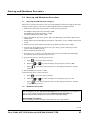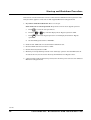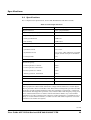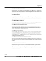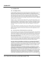
1
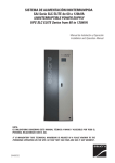
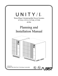
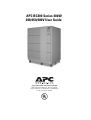
APC BC300 Series 40kW
208/450/480V User Guide
Copyright ©2002 APC Denmark ApS
This manual is subject to change without
notice and does not represent a commitment
on the part of the vendor
Thank You
Thank you for choosing the APC BC Series. Please read this User Guide thoroughly prior to
using the system as it provides important information on safe and efficient use.
The use of this product must comply with national, federal, state, municipal and local codes.
IMPORTANT SAFETY INSTRUCTIONS
SAVE THESE INSTRUCTIONS
Safety Symbols used in this manual
WARNING! Indicates a hazard which, if not avoided, could result in injury or death.
CAUTION!
Indicates a hazard which, if not avoided, could result in damage to the product or
other property.
NOTICE!
Read and pay attention to this important information.
WARNING!
This UPS unit contains hazardous AC and DC voltages. Only qualified electricians should
connect the UPS, AC line and external batteries, and must be familiar with batteries and battery
installation.
Before installing, maintaining or servicing the UPS, shut off the UPS and disconnect all sources
of AC and DC power.
As the UPS has no built-in disconnection devices to switch off external AC and DC input power,
ensure that disconnection devices are available as separate parts in connection with the
installation.
The installer must provide each external disconnecting device for this UPS system with labels
with the following text:
“Isolate the Uninterruptible Power Supply (UPS) as instructed in this guide before working on
circuit”
AC and/or DC voltage will always involve a potential risk of AC voltage at UPS output generated
from either batteries or utility. To avoid equipment damage or personal injury, always assume
that there may be voltage at UPS output.
This system is equipped with an auto-start function. If activated, the system may start without
warning. Refer to the “Programming” section for information on de-activation.
TEST BEFORE YOU TOUCH!
To reduce the risk of fire or electric shocks, install the UPS and external batteries in a
temperature and humidity controlled indoor area, free of conductive contaminants.
UPS batteries are high-current sources. Shorting battery terminals, DC terminals or DC busbars
can cause severe arcing, equipment damage and injury. A short circuit can cause a battery to
explode. Always wear protective clothing and eye protection and use insulated tools when
working on batteries.
CAUTION!
This unit contains components sensitive to electrostatic discharge (ESD). If you do not follow the
ESD procedures, you may cause severe damage to electronic components.
PLEASE RECYCLE
The shipping materials are recyclable. Please save for later use or dispose of them appropriately.
990-1403
2
User Guide APC BC300 Series 40kW 208/450/480V UPS
Contents:
1.0
2.0
3.0
4.0
5.0
6.0
7.0
8.0
9.0
10.0
11.0
Introduction
4
1.1
4
Display Unit
UPS Stop/Start
5
2.1
2.2
5
5
UPS Stop (for stand-by)
UPS Start (from stand-by)
Operation
6
3.1
3.2
3.3
7
8
9
Operation Modes
Using the Keys
Displaying Measurements
Parameter Settings
11
Alarms and Events
13
5.1
5.2
5.3
5.4
13
13
14
23
Silencing the Audible Alarm
Displaying the Alarm Log
Alarm Messages
Displaying the Events Log
Maintenance and Testing
24
6.1
6.2
6.3
24
24
25
Preventive Maintenance Check
Battery Monitor Test
Battery Capacity Test
Start-up and Shutdown Procedure
27
7.1
7.2
27
27
Start-up from Maintenance Bypass
Shutdown Procedure
Specifications
29
Options
31
9.1
9.1.1
9.1.2
9.1.3
9.2
9.2.1
9.2.2
9.2.3
9.2.4
9.2.5
9.2.6
9.2.7
9.2.8
31
31
31
31
31
31
32
32
32
32
32
32
32
Optional Hardware and Software Features
Battery Temperature
Communication
Maintenance
Optional Service Programs
Start-Up Service
Preventive Maintenance Visit
On-Site Service
Remote Monitoring Service
External Battery Installation Service
External Battery Start-up
External Battery Preventive Maintenance Visit
External Battery On-Site Service
WARRANTY
33
10.1
10.2
33
33
Life Support Policy
APC BC300 Series UPS Limited Factory Warranty
How to Contact APC
35
990-1403
User Guide APC BC300 Series 40kW 208/450/480V UPS
3
Introduction
1.0 Introduction
This UPS system is designed to offer reliable and problem-free power supply for several years.
The system requires only a minimum of maintenance, but we recommend you follow the
maintenance guidelines described in the “Maintenance & Testing” section of this User Guide.
1.1
Display Unit
The display unit (located on the front of the UPS) is the link between the user and the UPS and
consists of a display, an alarm LED indicator and a keyboard. The display reads parameters,
measured values and alarm messages.
Figure 1
NOTICE!
Display accuracy is ±2%, ±1digit.
990-1403
4
User Guide APC BC300 Series 40kW 208/450/480V UPS
UPS Stop/Start
2.0 UPS Stop/Start
WARNING!
AC voltage generated either from batteries or utility may be present at UPS output. Always
disconnect AC input supply source, switch off UPS, AND switch off DC.
TEST BEFORE YOU TOUCH!
Some UPS systems have a factory-set auto-start feature, which automatically switches on the
UPS whenever utility supply is switched on (AC line). See the “Parameter Settings” section in
this User Guide for instructions on how to de-activate this function.
Only qualified electricians should start up or shut down APC BC300 Series UPS systems, and
instructions in the Installation Guide should be followed. The UPS must be completely shut
down before service or before the UPS is taken out of operation for more than 24 hours.
Although you cannot completely start or shut down the unit, you can switch the UPS into
stand-by mode and return it to normal operation by following the instructions below. (In standby mode, the UPS does not provide output voltage.)
2.1
UPS Stop (for stand-by)
To put the unit into stand-by mode, press the red control button inside the unit’s front door.
2.2
UPS Start (from stand-by)
To take the unit out of stand-by and switch it back to normal operation, press the
green control button inside the unit’s front door.
.
NOTICE!
Make sure the UPS operates in normal operation for at least 12 hours every three months to
recharge the batteries.
990-1403
User Guide APC BC300 Series 40kW 208/450/480V UPS
5
Operation
3.0 Operation
The keyboard is used to program and control parameters and to display alarm messages and
measured values.
Figure 2
990-1403
6
User Guide APC BC300 Series 40kW 208/450/480V UPS
Operation
3.1
Operation Modes
The display automatically indicates which mode the unit is operating in. See Table 1 below for
sample display messages and an explanation of each.
Table 1: Operating Modes
Sample Display
Mode
Operation Mode Description
Normal Operation
load power ##%
The UPS is in the normal operation mode. During normal operation,
utility (AC line) passes through the UPS and to the load. The inverter
regulates the output and charges the batteries. The UPS measures
all three phases, and the display reads out the% load of the highest
loaded phase.
Battery Operation
time ## minutes
When AC input is out of tolerance (outside programmed limits), the
UPS is running in battery mode. The main static switch is open, and
the inverter is powered from the batteries. The power is then fed to
the loads. If the batteries are depleted, the unit will switch to standby mode (see below) and wait for utility to return in tolerance. If autostart is programmed to “ON,” the unit will automatically start about
30 seconds after utility has returned. If auto-start is programmed to
“OFF,” you must start the unit manually by pressing the green
button inside the front door. (See the “Parameter Settings” section in
this User Guide.)
Bypass Operation
The AC input passes unregulated through the bypass static switch,
through the main transformer, and to the loads. The UPS’ inverter is
in stand-by and is synchronized to the utility, ready to transfer the
unit to battery operation if utility voltage is out of tolerance.
Economy Mode
The unit has been programmed to operate in economy mode. The AC
power flows in bypass, and the UPS will periodically transfer to
normal operation to charge the batteries (at 7-day intervals by UPS
default). The inverter is in stand-by and is synchronized to utility,
ready to transfer to battery operation if utility voltage is out of
tolerance. The output voltage is not regulated in this mode, but
efficiency increases. Call APC Technical Support or your nearest
APC office for more information on programming your APC BC300
Series UPS for Economy Mode.
** Stand-by **
Both static switches are open. The unit is not supplying output
voltage.
990-1403
User Guide APC BC300 Series 40kW 208/450/480V UPS
7
Operation
3.2
Using the Keys
Table 2: Using the keys
Key
Function
Scroll up through lists of e.g.
parameters, alarms, or events.
Scroll down through lists of e.g.
parameters, alarms, or events.
Key
Function
Display the time and date. If the
unit is in the parameter mode,
use this key to change the setting
of a parameter from “OFF” to
“ON.”
Display inverter current.
Enter a value or exit a mode.
Display output frequency.
Display the alarm log. If the unit
is in the parameter mode, this
key changes the setting of a
parameter from “ON” to “OFF.”
Display utility (AC input)
current.
Display user parameters.
Display battery current.
Silence audible alarms.
Display output current.
Not used.
Display utility (AC input)
voltage.
Display battery voltage.
Display output voltage.
990-1403
8
User Guide APC BC300 Series 40kW 208/450/480V UPS
Operation
3.3
Displaying Measurements
The APC BC300 Series UPS measures several values during operation that you can display by
pressing one or two keys. This section illustrates how to display the measurements, what a
sample display of each measurement looks like, and what the display reads. If two keys are
shown, press those keys simultaneously. The display values shown below are samples
only.
Table 3: Display Measurements (Examples)
Key
Sample Display
Description
Utility 1. voltage 210 210 210 Vac
Utility (AC line) voltage is
3 x 210 Vac (L1-2, L2-3, L3-1).
Utility 1. current 21 21 21 Aac
Utility (AC line) current is 3 x 21 Aac (I1, I2,
I3).
Battery voltage 216 VDC
Battery voltage is 216 VDC.
Battery current 2 ADC (-30 ADC)
Charging current is (+) 2 ADC.
Discharging current is (-) 30 ADC.
Inverter current 12 12 12 Aac
Inverter current is 3 x 12 Aac.
Output voltage 208 208 208 Vac
Output voltage is 3 x 208 V (L1-2, L2-3, L3-1).
Output current 15 15 15 Aac
Output current is 3 x 15 Aac (I1, I2, I3).
Output frequency 60 Hz
Output frequency is 60 Hz.
990-1403
User Guide APC BC300 Series 40kW 208/450/480V UPS
9
Operation
When two keys are shown, press those keys simultaneously.
Keys
Sample Display
Description
Battery temp. 25° C
Battery temperature is 77° F (25° C)
Output peak curr 19 19 19
Aac
Output peak current is 3 x 19 Aac.
Normal operation load
power xx%
01.12.16
10.22.13 UTC
Returns to “Normal operation”
display and indicates the% load of the
most fully loaded phase (leg).
Year, month, day.
Hour, minute, second. UTC =
Universal Time Coordination. (This
may be programmed to your time.)
990-1403
10
User Guide APC BC300 Series 40kW 208/450/480V UPS
Parameter Settings
4.0 Parameter Settings
User parameters allow you to define the UPS settings. You can view and program the
parameters listed in Table 2 below. The parameters are easy to access and program: simply
follow the five steps below.
NOTICE!
Make sure that you fully understand a parameter before changing it.
Call APC Technical Support or your nearest APC office for assistance.
1. Press
to display the user parameter list.
2.
or
Press
to scroll through the list.
3. To switch a parameter “ON,” press
.
4. To switch a parameter “OFF,” press
5. To exit the parameter list, press
.
.
990-1403
User Guide APC BC300 Series 40kW 208/450/480V UPS
11
Parameter Settings
Table 4: Parameter Settings
PARAMETER
FACTORY
SETTING
DESCRIPTION
Second Language
OFF
If you select ON, the APC BC300 Series displays all
messages in its second language (Spanish).
Adaptive slewrate
ON
OFF is used when utility frequency is unstable. Call
APC Technical Support before changing this
parameter.
Battery monitor
reset
—
Choose ON to reset the battery monitor alarm and
remove battery monitor alarm messages from the
alarm log and to reset all battery information (e.g.
runtime); run a battery monitor test again (see the
“Battery Monitor Test” section of this User Guide) to
set battery information to the correct levels. This
parameter is available only for UPSs with a battery
monitor.
Battery monitor
test
—
This test measures the condition of the batteries.
(See the “Battery Monitor Test” section of this User
Guide). This parameter is available only for UPSs
with a battery monitor.
Battery capacity
test
—
Measures back-up time (runtime) available. See the
“Battery Capacity Test” section in this User Guide
for more information.
M3 start-up
—
Not applicable.
Boost charge
OFF
Set to ON for 8 hours (programmable) of continuous
boost (equalize) charge. For more information on
changing the time to more or less than 8 hours, call
APC Global Service.
Bypass operation
OFF
Switch to ON for static bypass operation. The UPS
must be programmed for static bypass operation
before an external bypass switch is activated in
order not to disturb the power to the load. While the
UPS is operating in bypass, the batteries are not
charged.
Auto-start
OFF
Set to ON for auto-start after 30 seconds when
utility (AC line) is applied. CAUTION: When this
parameter is set to ON, the UPS automatically
starts and powers the load whenever utility is
available. When servicing the UPS or load, make
sure this is set to OFF.
990-1403
12
User Guide APC BC300 Series 40kW 208/450/480V UPS
Alarms and Events
5.0 Alarms and Events
Alarms are indicated by a red light (above the left-hand corner of the display) and a 30-second
acoustic signal. An alarm is registered in the alarm log as long as it is present.
All alarms are also registered in an event logger and remain there in a stack with room for 250
events. The events are stored in order of occurance, with the latest event appearing first.
5.1
Silencing the Audible Alarm
To silence the audible alarm, press
The audible alarm will automatically silence itself after 30 seconds.
NOTICE!
Silencing the audible alarm does not correct the condition that caused the alarm.
5.2
Displaying the Alarm Log
To find out why the UPS sounds an alarm, display the alarm log by following steps 1-4
below.
The log shows all alarms currently active. Note each alarm!
1. Press
2. Press
to access the alarm log.
or
to move through the alarm log.
3. If you press
after displaying the last active alarm, the display will read:
“No further alarm.”
4. To exit the alarm log press
.
990-1403
User Guide APC BC300 Series 40kW 208/450/480V UPS
13
Alarms and Events
5.3
Alarm Messages
Table 5: Possible Alarms
Alarm
Message
Description
Action
Battery MCB is
off
The battery breaker is open. If
bypass voltage is within tolerance,
the unit transfers to static bypass
operation. If not, the unit transfers
to stand-by and does not supply
output voltage.
At the battery breaker, set the
precharge/discharge switch to the
precharge position and hold it in
this position until the LED turns
off. Precharge is very important
to prevent damage to your
equipment. After precharge,
switch the battery breaker on.
Battery Monitor
Alarms
The battery monitor test has found
that the battery pack is near low
runtime capacity or that the
battery pack may have a problem.
The unit’s status does not change,
but when the unit operates on
battery, runtime will be seriously
reduced.
Call APC Global Service to
schedule battery maintenance.
Battery Monitor
Warning
The battery monitor test has found
that battery capacity is reduced
(typically below 80%). The unit’s
status does not change, but the unit
will not be able to operate as long
on battery (it will have reduced
runtime).
See the “Parameter Settings”
section of this User Guide to
display the parameters. Then,
change the “Battery monitor
reset” parameter to “ON.” This
will clear the Battery Monitor
Warning. Next, do a battery
monitor test (see the “Battery
Monitor Test” section). If the
alarm starts again, call APC
Global Service to schedule
battery maintenance.
Bypass freq. is
out of tolerance
The bypass frequency is out of
tolerance (too high, low, or
unstable). The unit may transfer to
battery or stand-by operation; it
cannot operate in static bypass.
Ask an electrician to make sure
that the correct input frequency is
being supplied to the UPS. If so,
and if this voltage is within the
range accepted by the UPS, call
APC Global Service.
Bypass is
moment. out of
tolerance (This
alarm occurs
when there is a
power outage)
The bypass voltage was
momentarily out of tolerance. The
unit may transfer to battery or
stand-by operation; it cannot
operate in static bypass.
Ask an electrician to make sure
that the correct input voltage is
being supplied to the UPS. If so,
and if this voltage is within the
range accepted by the UPS, call
APC Global Service.
Bypass is out of
tolerance (This
alarm occurs
when there is a
power outage)
The bypass voltage is out of
tolerance (too high or low). The unit
may transfer to battery or stand-by
operation; it cannot operate in
static bypass.
Ask an electrician to make sure
that the correct input voltage is
being supplied to the UPS. If so,
call APC Global Service.
990-1403
14
User Guide APC BC300 Series 40kW 208/450/480V UPS
Alarms and Events
Table 5: Possible Alarms
Charge reg.
error (reg. =
regulator)
Failure in charge regulation. The
unit transfers to battery until the
“Low DC shutdown” alarm occurs;
then, it transfers to stand-by and
does not supply output voltage.
Call APC Global Service.
External service
switch activated
The external service bypass switch
is in the line position. The unit is in
stand-by and does not supply
output voltage. However, the loads
may be receiving power from the
external manual bypass.
Call APC Global Service.
Fan fault
If the fan monitoring option is
installed, this alarm sounds if one
or more of the fans are slowing
down. The unit’s status does not
change, but the problem may cause
other high-temperature alarms
that could change the unit’s status.
Call APC Global Service.
Fatal Error
RAM1 data
error
Components on the main controller
board have failed.
Call APC Global Service.
Fault in int.
power supply
There is a fault in the internal
power supply unit (PSU). The UPS
transfers to stand-by and does not
supply output voltage.
Call APC Global Service.
High Battery
Temperature
The ambient battery temperature
is higher than the set alarm level.
The unit’s status does not change,
but battery life could be affected.
This alarm is often caused by high
room temperature.
Make sure the room temperature
does not exceed 80° F (27° C). If
so, cool down the room. If the
temperature was below 80° F (27°
C) at the time of the alarm, find
the exhaust vents for the UPS
fans and check to see if the fans
are operating. Do not try to open
the unit, and do not insert
anything into a fan vent. If the
fans are not operating, call APC
Global Service.
High DC
Warning
The monitored battery voltage is
higher than the unit’s shutdown
setting.
Call APC Global Service.
High DC
Shutdown
The monitored battery voltage is
higher than the unit’s shutdown
setting. The unit will switch to
battery power to reduce DC bus
voltage.
Call APC Global Service.
990-1403
User Guide APC BC300 Series 40kW 208/450/480V UPS
15
Alarms and Events
Table 5: Possible Alarms
High output
voltage (This
alarm is usually
only listed in the
events log)
The output voltage is higher than
the alarm setting. The unit stays in
the normal operation mode. If the
alarm is not cleared, the unit will
transfer to static bypass operation
if bypass is within tolerance. If
bypass is not within tolerance, the
unit will transfer to stand-by and
will not supply output voltage.
If the alarm is still active, put the
UPS into bypass by displaying
the user parameters and
changing “Bypass Operation” to
“ON.” (See the “Parameter
Settings” section in this User
Guide). Then, call APC Global
Service.
High temp.
choke
The temperature in the main choke
is too high. If the problem is not
corrected soon, the unit will
transfer to battery operation.
Find the exhaust vents for the
UPS fans and check to see if the
fans are operating. Do not try to
open the unit, and do not insert
anything into a fan vent. If the
fans are not operating, call APC
Global Service.
High temp.
transformer
The temperature in the main
transformer is too high. If the
problem is not corrected soon, the
unit will transfer to stand-by and
will not supply output voltage.
Find the exhaust vents for the
UPS fans and check to see if the
fans are operating. Do not try to
open the unit, and do not insert
anything into a fan vent. If the
fans are not operating, call APC
Global Service.
Inverter fuse
blown
One or more of the fuses at the
output of the inverter are blown
(F004, F005, F006). If bypass is
within tolerance, the unit transfers
to static bypass operation. If not,
the unit transfers to stand-by and
does not supply output voltage.
Call APC Global Service.
Inverter voltage
error
The output voltage is too high or too
low. If the alarm was caused by
high output voltage, the unit
transfers to static bypass operation
if bypass is within tolerance. If
bypass is not within tolerance, the
unit transfers to stand-by and does
not supply output voltage. If the
alarm was caused by low output
voltage, the unit transfers to static
bypass operation if bypass is within
tolerance. If bypass is not within
tolerance, the unit transfers to
battery for five seconds and then
transfers to stand-by and stops
supplying output voltage.
If the UPS is in stand-by, restart
the UPS by pressing the green
button inside the door. If the UPS
will not restart, a user may have
started an emergency power off
(EPO) shutdown. Find out if the
EPO shut down the UPS; if it did,
find out why and make sure the
emergency situation has passed.
Then, reset the EPO and restart
the unit by pressing the green
button inside the door. If the unit
will still not restart, call APC
Global Service.
990-1403
16
User Guide APC BC300 Series 40kW 208/450/480V UPS
Alarms and Events
Table 5: Possible Alarms
Low DC
shutdown (This
alarm is normal
when the UPS
has run on
battery for a
long time)
The UPS has been running on
battery power because of a power
outage or problems in the AC input.
Battery voltage has dropped below
the shutdown setting, and the UPS
has shut down. If bypass is within
tolerance, the unit will transfer to
static bypass operation. If not, the
unit will transfer to stand-by and
will not supply output voltage.
If the UPS is programmed for
auto-start, it will automatically
restart when the power outage
ends and AC input is again
available. If the UPS is not
programmed for auto-start, you
can restart the UPS when the
power outage ends by pressing
the green button inside the door.
Low DC
warning (This
alarm is normal
when the UPS
has run on
battery for a
while)
The UPS has been running on
battery power for a while because of
a power outage or problems in the
AC input. Battery voltage has
fallen to the warning alarm setting.
If the APC BC300 Series is
operating on battery, the unit’s
status will not change, but battery
voltage will eventually drop to the
shutdown setting. At this point, the
unit will shut down and sound a
“Low DC shutdown” alarm. If the
“Low DC warning” alarm occurs
during a battery capacity test, the
unit transfers back to normal
operation.
If possible, restore AC input
power to the UPS. If you cannot
do this, prepare for a possible Low
DC shutdown by shutting down
the loads (protected equipment)
connected to the UPS.
If the unit has not been running on
battery power, call APC Technical
Support.
Mains freq. is
out of tolerance
The utility (AC input) frequency is
out of tolerance. The unit transfers
to battery operation. If utility
returns to a frequency within
tolerance, the unit transfers back to
normal operation. If not, the unit
continues to run on battery until
the “Low DC shutdown” alarm
occurs. Then, if bypass is within
tolerance, the unit transfers to
bypass. If not, the unit transfers to
stand-by and does not supply
output voltage.
Ask an electrician to make sure
that the correct input frequency is
available to the UPS. The
electrician must correct any
problems in input frequency. If
input frequency is correct, call
APC Global Service.
Mains is
moment. out of
tolerance (This
alarm occurs
during a power
outage)
The utility (AC line voltage) was
momentarily too high or too low.
The unit transfers to battery; if
utility returns to a frequency
within tolerance, the unit transfers
back to normal operation.
If possible, restore AC input
power to the UPS. If AC input is
available to the UPS, ask an
electrician to make sure that 1)
the correct input voltage is
available to the UPS. 2) this
voltage is within an acceptable
UPS range
990-1403
User Guide APC BC300 Series 40kW 208/450/480V UPS
17
Alarms and Events
Table 5: Possible Alarms
Mains is out of
tolerance (This
alarm occurs
during a power
outage)
The utility (AC input) voltage is too
high or too low, so the unit
transfers to battery operation. If
AC input returns to normal, the
unit transfers back to normal
operation. If not, the unit continues
to run on battery until the “Low DC
shutdown” alarm occurs. Then, if
bypass voltage is within the range
programmed into the UPS, the unit
transfers to bypass. If not, the unit
transfers to stand-by and does not
supply output voltage.
If possible, restore AC input
power to the UPS. If AC input is
available to the UPS, ask an
electrician to make sure that 1)
the correct input voltage is
available to the UPS, and 2) this
voltage is within a range the UPS
will accept.
OFF Button
Pushed (If the
alarm was
caused by the
Off button, it is
in the events
log)
A user pushed the red “Off” button
or activated an emergency power
off shutdown. The unit switches to
stand-by mode and does not supply
output voltage.
Restart the unit by pressing the
green button inside the door. If
the unit will not restart, the
alarm was caused by an
emergency power off (EPO)
shutdown. Find out why this
shutdown was activated and
make sure the emergency
situation has passed; then,
restart the unit by deactivating
the emergency power off
shutdown.
Output freq. is
out of tolerance
The output frequency is too high,
low, or unstable (out of tolerance).
The unit transfers to battery
operation and runs on battery until
the “Low DC shutdown” alarm
occurs. Then, the unit transfers to
bypass if bypass is within
tolerance. If not, the unit transfers
to stand-by and does not supply
output voltage.
Ask an electrician to make sure
that the correct input frequency is
being supplied to the UPS. Then,
call APC Global Service.
Output is
moment. out of
tolerance
The output voltage was
momentarily too high or too low
(out of tolerance). If bypass is
within tolerance, the unit transfers
to static bypass operation. If not,
the unit transfers to stand-by and
does not supply output voltage.
If other alarms are also active,
troubleshoot these alarms first. If
this is the only alarm, call APC
Global Service.
990-1403
18
User Guide APC BC300 Series 40kW 208/450/480V UPS
Alarms and Events
Table 5: Possible Alarms
Output is out of
tolerance
The output voltage is too high or too
low (out of tolerance). If the alarm
was caused by high output voltage,
the unit transfers to static bypass
operation if bypass is within
tolerance. If bypass is not within
tolerance, the unit transfers to
stand-by and does not supply
output voltage. If the alarm was
caused by low output voltage, the
unit transfers to static bypass
operation if bypass is within
tolerance. If bypass is not within
tolerance, the unit transfers to
battery for five seconds and then
transfers to stand-by and stops
supplying output voltage.
If the UPS is in stand-by, restart
the UPS by pressing the green
button inside the door. If the UPS
will not restart, a user may have
started an emergency power off
(EPO) shutdown. Find out if the
EPO shut down the UPS; if it did,
find out why and make sure the
emergency situation has passed.
Then, you can reset the EPO and
restart the unit by pressing the
green button inside the door. If
the unit will still not restart, call
APC Global Service.
Overload load is
over 100%
The unit is loaded with more than
nominal load on one or more
phases. The UPS status does not
change until it can no longer
maintain the correct output
voltage. Then, the unit transfers to
static bypass operation if bypass is
within tolerance. If not, the unit
transfers to battery for five
seconds; then, it transfers to standby and stops supplying output
voltage.
Disconnect equipment connected
to the UPS until the load is below
100%. An electrician must
connect these loads to another
power source. If the alarm
persists, call APC Global Service.
Static switch 1
temp. shutdown
The temperature on the heat-sink
for the main static switch is higher
than the shutdown level, and the
main static switch has opened. The
unit switches to battery operation.
When the temperature falls below
the shutdown level, the unit
transfers back to normal operation.
If the temperature does not fall to
this level before the “Low DC
Shutdown” alarm occurs, there will
be no output to the load equipment.
Find the vents for the UPS fans
and check to see if the fans are
operating. Do not try to open the
unit, and do not insert anything
into a fan vent. If the fans are not
operating, call APC Global
Service. If the fans are operating,
make sure the room temperature
is below 80° F (27° C). If not, cool
down the room. if the room was
already below this temperature,
call APC Global Service.
990-1403
User Guide APC BC300 Series 40kW 208/450/480V UPS
19
Alarms and Events
Table 5: Possible Alarms
Static switch 1
temp. warning
The temperature on the heat-sink
for the main static switch is higher
than the warning setting. The
unit’s status does not change.
However, if the temperature
continues to rise, the unit will
sound a “Static switch 1 temp.
shutdown” alarm.
Find the vents for the UPS fans
and check to see if the fans are
operating. Do not try to open the
unit, and do not insert anything
into a fan vent. If the fans are not
operating, call APC Global
Service. If the fans are operating,
make sure the room temperature
is below 80° F (27° C). If not, cool
down the room. if the room was
already below this temperature,
call APC Global Service.
Static switch 2
temp. shutdown
The temperature on the heat-sink
for the bypass static switch is
higher than the shutdown level and
the bypass static switch has
opened. The unit switches to
battery operation until the
temperature falls below the
shutdown level; then, it transfers
back to normal operation. If the
temperature does not fall to this
level before the “Low DC
shutdown” alarm occurs, there will
be no output to the load equipment.
Find the vents for the UPS fans
and check to see if the fans are
operating. Do not try to open the
unit, and do not insert anything
into a fan vent. If the fans are not
operating, call APC Global
Service.
If the fans are operating, make
sure the room temperature is
below 80° F (27° C). If not, cool
down the room. if the room was
already below this temperature,
call APC Global Service.
Static switch 2
temp. warning
The temperature on the heat-sink
for the bypass static switch is
higher than the warning setting.
The unit’s status does not change.
However, if the temperature
continues to rise, the unit will
sound a “Static switch 2 temp.
shutdown” alarm.
Find the vents for the UPS fans
and check to see if the fans are
operating. Do not try to open the
unit, and do not insert anything
into a fan vent. If the fans are not
operating, call APC Global
Service.
If the fans are operating, make
sure the room temperature is
below 80° F (27° C). If not, cool
down the room. if the room was
already below this temperature,
call APC Global Service.
Synchronization
error (This
alarm occurs
during a power
outage)
The inverter output is not
synchronized to the utility (AC
input). The unit will transfer to
battery operation until the “Low
DC shutdown” alarm sounds. If the
unit can synchronize to utility
again before this event occurs, it
will transfer back to normal
operation.
If this alarm occurs during the
initial start-up, an electrician
must check the phase rotation.
If this alarm occurs while the unit
is connected to a generator, the
unit may be having problems
synchronizing to the generator.
Call APC Global Service.
If the alarm does not occur during
the initial start-up and the UPS is
not connected to a generator, call
APC Global Service.
990-1403
20
User Guide APC BC300 Series 40kW 208/450/480V UPS
Alarms and Events
Table 5: Possible Alarms
TSM 1 temp.
shutdown
Inverter module 1 has shut down
because the temperature on the
heat-sink is higher than the
shutdown level. If bypass is within
tolerance, the unit transfers to
static bypass operation. If not, the
unit transfers to stand-by mode
and does not supply output voltage.
Find the vents for the UPS fans
and check to see if the fans are
operating. Do not try to open the
unit, and do not insert anything
into a fan vent. If the fans are not
operating, call APC Global
Service.
If the fans are operating, make
sure the room temperature is
below 80° F (27° C). If not, cool
down the room. if the room was
already below this temperature,
call APC Global Service.
TSM 1 temp.
warning
The temperature on the heat-sink
for inverter module 1 has exceeded
the warning setting. The unit’s
status does not change. However, if
the temperature continues to rise,
the unit will sound a “TSM 1 temp.
shutdown” alarm.
Find the vents for the UPS fans
and check to see if the fans are
operating. Do not try to open the
unit, and do not insert anything
into a fan vent. If the fans are not
operating, call APC Global
Service.
If the fans are operating, make
sure the room temperature is
below 80° F (27° C). If not, cool
down the room. if the room was
already below this temperature,
call APC Global Service.
TSM 2 temp.
shutdown
Inverter module 2 has shut down
because the temperature on the
heat-sink is higher than the
shutdown level. If bypass is within
tolerance, the unit transfers to
static bypass operation. If not, the
unit transfers to stand-by and does
not supply output voltage.
Find the vents for the UPS fans
and check to see if the fans are
operating. Do not try to open the
unit, and do not insert anything
into a fan vent. If the fans are not
operating, call APC Global
Service. If the fans are operating,
make sure the room temperature
is below 80° F (27° C). If not, cool
down the room. if the room was
already below this temperature,
call APC Global Service.
TSM 2 temp.
warning
The temperature on the heat-sink
for inverter module 2 is higher than
the warning setting. The unit’s
status does not change. However, if
the temperature continues to rise,
the unit will sound a “TSM 2 temp.
shutdown” alarm.
Find the vents for the UPS fans
and check to see if the fans are
operating. Do not try to open the
unit, and do not insert anything
into a fan vent. If the fans are not
operating, call APC Global
Service. If the fans are operating,
make sure the room temperature
is below 80° F (27 °C). If not, cool
down the room. if the room was
already below this temperature,
call APC Global Service.
990-1403
User Guide APC BC300 Series 40kW 208/450/480V UPS
21
Alarms and Events
Table 5: Possible Alarms
TSM 3 temp.
shutdown
Inverter module 3 has shut down
because the temperature on the
heat-sink is higher than the
shutdown level. If bypass is within
tolerance, the unit transfers to
static bypass operation.
If not, the unit transfers to standby and does not supply output
voltage.
Find the vents for the UPS fans
and check to see if the fans are
operating. Do not try to open the
unit, and do not insert anything
into a fan vent. If the fans are not
operating, call APC Global
Service.
If the fans are operating, make
sure the room temperature is
below 80° F (27° C). If not, cool
down the room. if the room was
already below this temperature,
call APC Global Service.
TSM 3 temp.
warning
The temperature on the heat-sink
for inverter module 3 is higher than
the warning setting. The unit’s
status does not change. However, if
the temperature continues to rise,
the unit will sound a “TSM 3 temp.
shutdown” alarm.
Find the vents for the UPS fans
and check to see if the fans are
operating. Do not try to open the
unit, and do not insert anything
into a fan vent. If the fans are not
operating, call APC Global
Service.
If the fans are operating, make
sure the room temperature is
below 80° F (27° C). If not, cool
down the room. if the room was
already below this temperature,
call APC Global Service.
990-1403
22
User Guide APC BC300 Series 40kW 208/450/480V UPS
Alarms and Events
5.4
Displaying the Events Log
The events log is a list of the last 250 alarms and operational modes. This log includes the time
and date of each event. Most entries in this log will be alarms (see the “Alarms and
Events” section in this User Guide for a description of alarms). Other entries describe
operating modes (see the “Operation Modes” section in this User Guide for details); the table
below lists and describes these Event Log messages.
1. To access the events log, press both
2. Use the
and
and
at the same time.
keys to scroll through the log.
3. To display the time and date the alarm or other event occurred, press
Sample display:
.
01.12.16 (Year, month, date)
10.22.13 UTC (Hour, minute, second. UTC = Universal Time Coordination.)
4. If you press
event.”
after displaying the last event in the log, the display will show “No further
5. To exit the events log, press
.
Table 6: Log Messages
Mode
Description
Main processor unit (MPU) is reset
The UPS was completely switched off.
Stand-by
The UPS was in stand-by mode.
Normal operation
The UPS was in normal operation.
Bypass operation
The UPS was in bypass operation.
Battery operation
The UPS was in battery operation.
Economy operation
The UPS was programmed to operate in economy
mode.
990-1403
User Guide APC BC300 Series 40kW 208/450/480V UPS
23
Maintenance and Testing
6.0 Maintenance and Testing
APC recommends a periodic preventive maintenance check every six months. APC also
recommends that the cooling fans be replaced every three years.
6.1
Preventive Maintenance Check
At the preventive maintenance check, a qualified service technician should:
•
Check all wiring connections.
•
Inspect and clean the unit.
•
Check the batteries.
•
Check the AC and DC meter functions.
•
Perform a battery capacity or battery monitor test. (See the sections “Battery
Monitor Test” and “Battery Capacity Test” in this User Guide.)
•
Check all modes of operation.
•
Perform a power outage test.
Safety precautions must be observed while performing maintenance checks. For more
information on preventive maintenance checks, or to schedule a maintenance check with an
APC-authorized field service representative, call APC Global Service or the nearest APC office.
6.2
Battery Monitor Test
NOTICE!
If you are using UPS contacts for a communication link, take the necessary precautions so this
test will not cause a premature shutdown. See your software documentation for more
information.
The battery monitor is optional for units with external batteries. The steps on the next page
illustrate how to start a battery monitor test. This test measures the condition of the batteries
and compares it to data programmed into the unit. The test discharges the batteries to about
75% of their capacity. During this test, the unit checks the applied load and the ambient
temperature of the batteries. The unit then compares the results of the test with its
programmed data. If the unit determines that the condition of the batteries is acceptable, it
returns to normal operation. If the test determines that the condition of the batteries is
unacceptable, the unit will sound either a “Battery monitor warning” alarm or a “Battery
monitor alarm.” See Possible Alarms table 5 for more information on these alarms. If you would
like the unit to automatically perform a battery monitor test on a regular basis (default = every
90 days), call the nearest APC office for more information.
NOTICE!
The information programmed into the unit is based on the size and type of batteries that were
installed when the unit was sold. If the battery configuration changes, this test will not be
accurate for the new configuration. Call the nearest APC office for more information.
990-1403
24
User Guide APC BC300 Series 40kW 208/450/480V UPS
Maintenance and Testing
To perform a battery monitor test:
1. Press
to display the user parameters.
2. Press
test.”
or
3. Press
min.”
to start the battery monitor test. The display shows “Batt. operation time > xxx
to scroll through parameters until the display shows “Battery monitor
(“xxx” = the minutes of runtime remaining. This number will fluctuate during the test.)
4. When the test is complete, the display will show “Normal operation load power xx%” if the
batteries are in acceptable condition. If the test has determined that the condition of the
batteries is unacceptable, the unit will display either a “Battery monitor warning” or
“Battery monitor alarm.” See the “Alarm Messages” section for a detailed description of
these alarms.
6.3
Battery Capacity Test
NOTICE!
If you are using UPS contacts for a communication link, take the necessary precautions so this
test will not cause a premature shutdown. See your software documentation for more
information.
The battery capacity test discharges the batteries to the “Low DC warning” level and displays
the estimated runtime. This estimate is only correct for the unit’s condition at the time of the
battery capacity test. If the load changes and you would like to display the estimated runtime,
you must perform this test again. After a battery capacity test, the unit must charge the
batteries for at least eight hours before full battery capacity and full runtime have been
restored.
To perform a battery capacity test, follow these steps:
1. Press
to display the user parameters.
2. Press
or
to scroll through the parameters until the display shows this:
Battery capacity test: xxx
(“xxx” = the backup time from the last test). If the test has never been performed before or if
the test has been aborted, the display will show “???.”
3. Press
to abort the test or
“Batt. operation time xxx min.”
to continue. The display shows
4. If you wish to abort the test while it is in progress, follow these steps:
990-1403
User Guide APC BC300 Series 40kW 208/450/480V UPS
25
Maintenance and Testing
a.
Display the user parameter list by pressing
.
b.
Use the arrow keys to scroll through the parameters until the display shows “Battery
capacity test: xxx.”
c.
Switch the battery capacity test “OFF” by pressing
.
5. Wait until the display shows “Normal operation load power xx%” and a short alarm
sounds.
6. Press
. The display will show “Battery capacity test: xxx.” (“xxx” = the estimated
backup time in minutes)
7. Press
to exit the user parameter list.
990-1403
26
User Guide APC BC300 Series 40kW 208/450/480V UPS
Start-up and Shutdown Procedure
7.0 Start-up and Shutdown Procedure
7.1
Start-up from Maintenance Bypass
This section contains instructions on how to start the UPS from maintenance bypass. The steps
in this procedure apply to units with an APC-supplied Maintenance Bypass Panel.
1. Make sure that the following switches are in the following positions:
The UPS AC disconnect switch should be “OFF”.
The UPS bypass switch should be on “LINE”.
The battery breaker should be “OFF”.
2. Switch the UPS AC disconnect switch “ON”. The UPS display should show “System type
xxkVA xxxV”.
3. Within 20 seconds, the UPS display should show **Stand-by** and an audible alarm should
sound.
4. Ensure that the external battery breaker for the battery system is set to “OFF”.
5. Turn the pre-charge/discharge switch to the “pre-charge” position and keep it in this
position until the LED turns off.
6. Switch the battery breaker “ON”.
7. Press the green “on” button located inside the front door of the UPS. The UPS display
should show “Normal operation load power xx%”.
8. Program the unit into static bypass operation:
a.
Press
to access the user parameters.
b.
Press the
c.
Press
to turn static bypass operation on. The display should show “Bypass
operation”.
or
key until the display shows “Bypass operation: OFF”.
9. Set the UPS bypass switch to “UPS”.
10. Program the unit to normal operation:
a.
Press
b.
Press the
c.
Press
to turn static bypass operation off. The display should show “Normal
operation load power xx%”.
7.2
to access the user parameters.
or
key until the display shows “Bypass operation: ON”.
Shutdown Procedure
WARNING
After shutting down the unit, wait at least five minutes before removing any access panels or
covers. Access panels should be removed by authorized service personnel only.
After the UPS has been shut down, the unit may still contain high voltages.
TEST BEFORE YOU TOUCH!
Before continuing, read the warnings on the inside front cover of this manual.
990-1403
User Guide APC BC300 Series 40kW 208/450/480V UPS
27
Start-up and Shutdown Procedure
This section contains information on how to shut down the UPS from normal operation mode.
This procedure applies to units with an APC-supplied Maintenance Bypass Panel.
1. If you have shut the loads down: Move on to step 2.
If the loads are to remain powered: Program the unit into static bypass operation:
a.
Press
to access the user parameters.
b.
Press the
c.
Press
to turn static bypass operation on. The display should show “Bypass
operation”.
d.
Set the UPS bypass switch to “BYPASS”.
or
key until the display shows “Bypass operation: OFF”.
2. Press the red “OFF” button located inside the UPS front door.
3. Set the UPS AC disconnect switch to “OFF”.
4. Switch the battery breaker “OFF”
5. Hold the pre-charge/discharge switch in the “discharge” position until the LED turns off.
To restart the unit, see the section “Start-up from Maintenance Bypass” above.
6. (Optional) If the loads are not to be powered, turn off all AC power sources to the UPS and
Maintenance Bypass Panel.
990-1403
28
User Guide APC BC300 Series 40kW 208/450/480V UPS
Specifications
8.0 Specifications
For a complete list of specifications, see the APC BC300 Series Installation Guide.
Table 7: General Specifications
Utility tolerance
+10%, —15% (programmable)
Bypass tolerance
±10% (programmable)
Input frequency ±6% (programmable)
60 Hz
Output frequency
- utility synchronized:
60 Hz ±6%
- free running:
60 Hz ±0.1%
Current distortion
0-5%
Tolerance
- symmetrical load:
±1%, static.
- asymmetrical load:
±3%, static. (100% imbalance, provided
output current rating is not exceeded.)
- load step 0-100:
±5%.
Distortion (linear load)
0-3%
Overload capacity
- normal operation, 1 minute
250%
- normal operation, 10 minutes
150%
- battery operation, 1 minute
150%
- battery operation, 10 minutes
125%
Audible noise (dBa)
dBa
Maximum Humidity (non condensing)
95%
Efficiency
95%
For Users in the United States Only
This equipment has been tested and found to comply with the limits for a Class A digital
device, pursuant to Part 15 of the FCC rules. These limits are designed to provide reasonable
protection against harmful interference when the equipment is operated in a commercial
environment. This equipment generates, uses, and can radiate radio frequency energy and,
if not installed and used in accordance with the Installation Guide, may cause harmful
interference to radio communications. Operation of this equipment in a residential area is
likely to cause harmful interference, in which case the user will be required to correct the
interference at his/her own expense.
990-1403
User Guide APC BC300 Series 40kW 208/450/480V UPS
29
Specifications
For Users in Canada
This digital apparatus does not exceed the Class A limits for radio noise emissions from
digital apparatus set out in the Radio Interference Regulations of the Canadian Department
of Communications.
990-1403
30
User Guide APC BC300 Series 40kW 208/450/480V UPS
Options
9.0 Options
APC offers many options for the APC BC300 Series UPSs. For more information, contact your
local APC office. Note that some options only apply to certain models.
9.1
Optional Hardware and Software Features
9.1.1 Battery Temperature
Compensation:
Enables the UPS to adapt the charging voltage to the battery temperature. This is for units
with external batteries and this option monitors the temperature in one battery cabinet.
9.1.2 Communication
Interface Board:
If you would like to use shutdown software or remote monitoring, your UPS must have this
internal circuit board. The board offers three methods of communicating with the UPS:
1. Normally open or normally closed contacts that indicate UPS ON, bypass operation, battery
operation, and low battery. (You can choose this method for an AS/400 monitoring system.)
2. RS232 Serial Communications port.
3. Zero to 20 mA current loop.
Fan Monitor:
If the unit’s fans are not functioning properly, this option will activate a “Fan fault” alarm.
9.1.3 Maintenance
Bypass Panel:
An external bypass switch lets you conveniently transfer your protected load equipment to
direct AC input power when it is time to service the UPS. The cabinet includes an AC
disconnect.
Parallel Board:
This option allows your qualified installer to connect two or more units in parallel. The parallel
board ensures proper control of parallel units and proper load sharing between the units. Each
unit to be connected in parallel requires one of these boards. Each board includes 23 feet (7
meters) of interconnection cable. An APC Application Engineer should be involved in all
parallel unit installations. Call APC Global Service or the nearest APC office for details.
9.2
Optional Service Programs
Contact APC or visit www.apc.com for further information on a large range of end-to-end
service and support which supplements the APC BC300 Series UPS Limited Factory
Warranty.
9.2.1 Start-Up Service
This service verifies that the APC system has been properly installed and includes
comprehensive tests, correct start-up and basic customer training on usage. Performed during
normal business hours. Does not include electrical installation or wiring work.
990-1403
User Guide APC BC300 Series 40kW 208/450/480V UPS
31
Options
9.2.2 Preventive Maintenance Visit
Provides a single visit to examine the status and health of the APC system, to ensure proper
operation over time. A visual and electronic inspection is performed to ensure that the system
is performing to all defined technical and environmental specifications. The service is
performed during normal business hours.
9.2.3 On-Site Service
Provides 1-year On-Site Repair Service on APC equipment and 7x24 Telephone Technical
Support. Response time differs by contracts. Based on availability the following contracts are
offered: best endeavour, next business day, next day and 4-hours. Parts, internal batteries (if
applicable), labor and travel are included.
9.2.4 Remote Monitoring Service
Provides 7x24 remote monitoring of your APC hardware via APC’s Network Operation Center.
Remote Monitoring Service is included for free during the first six months.
9.2.5 External Battery Installation Service
This service provides APC authorized personnel to install external batteries into racks or
cabinets. APC will energize and check functionality of the battery system in all modes, to
ensure compliance with Manufacturers technical specifications. Does not include wiring or
cabling. Performed during normal business hours
9.2.6 External Battery Start-up
Provides an APC authorized engineer to perform Start-Up of external standard APC battery
solutions for 208V/480V systems or DC systems. The engineer will energize and check the
functionality of the battery system in all modes to ensure compliance with manufacturers
technical specifications. The External Battery Start-Up will be performed in conjunction with
the Start Up of the UPS/power system.
9.2.7 External Battery Preventive Maintenance Visit
This service provides external battery inspection and testing to ensure proper operation over
time. Performed whenever the customer requires to schedule the visit - including weekends &
holidays.
9.2.8 External Battery On-Site Service
Provides a 1-year maintenance contract on external battery solutions, to ensure optimum
battery lifetime and performance. This service includes: 1-Year On-Site repair on APC
approved external batteries, including spare parts, labor and travel expenses. The External
Battery On-Site Service response time is equivalent to the response time of the APC hardware
On-Site Service contract.
990-1403
32
User Guide APC BC300 Series 40kW 208/450/480V UPS
WARRANTY
10.0 WARRANTY
10.1 Life Support Policy
As a general policy, American Power Conversion (APC) does not recommend the use of any of its
products in life support applications where failure or malfunction of the APC product can be
reasonably expected to cause failure of the life support device or to significantly affect its safety or
effectiveness. APC does not recommend the use of any of its products in direct patient care. APC
will not knowingly sell its products for use in such applications unless it receives in writing
assurances satisfactory to APC that (a) the risks or injury or damage have been minimized, (b() the
customer assumes all such risks, and (c) the liability of American Power Conversion is adequately
protected under the circumstances.
Examples of devices considered to be life support devices are neonatal oxygen analysers, nerve
stimulators (whether used for anaesthesia, pain relief, or other purposes), autotransfusion devices,
blood pumps, defibrillators, arrhythmia detectors and alarms, pacemakers, hemodialysis systems,
peritoneal dialysis systems, neonatal ventilator incubators, ventilators for both adults and infants,
anaesthesia ventilators, infusion pumps, and any other device designated as “critical” by the
U.S.F.D.A.
Hospital grade wiring devices and leakage current may be ordered as options on many APC UPS
systems. APC does not claim that units with this modification are certified or listed as Hospital Grade
by APC or any other organization. Therefore these units do not meet the requirements for use in
direct patient care.
10.2 APC BC300 Series UPS Limited Factory Warranty
APC warrants that the unit, when properly installed and commissioned by APC or APC authorized
service personnel, shall be free from defects in materials and workmanship for a period of (1) year
from the date of installation or maximum 18 months after manufacturing. In the event that the unit
fails to meet the foregoing warranty, APC shall for a period of one (1) year repair or replace any
defective parts, without charge for on-site labor and travel if trained & authorized APC personnel
has conducted start-up of the unit.
An APC Start-Up Service must be performed/completed by APC or service personnel authorized by
APC or the on-site factory warranty will be voided and replacement of defective parts only will be
covered. APC shall have no liability and no obligation to repair the installed unit if non-authorized
APC personnel performed the start-up and such start-up caused the unit to be defective.
APC SHALL NOT BE LIABLE UNDER THE WARRANTY IF ITS TESTING AND EXAMINATION
DISCLOSE THAT THE ALLEGED DEFECT IN THE PRODUCT DOES NOT EXIST OR WAS
CAUSED BY PURCHASER’S OR ANY THIRD PERSON’S MISUSE, NEGLIGENCE, IMPROPER
INSTALLATION OR TESTING, UNAUTHORIZED ATTEMPTS TO REPAIR OR MODIFY, OR ANY
OTHER CAUSE BEYOND THE RANGE OF THE INTENDED USE, OR BY ACCIDENT, FIRE,
LIGHTNING OR OTHER HAZARD.
THERE ARE NO WARRANTIES, EXPRESSED OR IMPLIED, BY OPERATION OF LAW OR
OTHERWISE, OF PRODUCTS SOLD, SERVICED OR FURNISHED UNDER THIS AGREEMENT
OR IN CONNECTION HEREWITHIN. APC DISCLAIMS ALL IMPLIED WARRANTIES OF
MERCHANTABILITY, SATISFACTION AND FITNESS FOR A PARTICULAR PURPOSE. APC’S
EXPRESS WARRANTIES WILL NOT BE ENLARGED, DIMINISHED, OR AFFECTED BY AND NO
OBLIGATION OR LIABILITY WILL ARISE OUT OF, APC’S RENDERING OF TECHNICAL OR
OTHER ADVICE OR SERVICE IN CONNECTION WITH THE PRODUCTS. THE FOREGOING
WARRANTIES AND REMEDIES ARE EXCLUSIVE AND IN LIEU OF ALL OTHER WARRANTIES
990-1403
User Guide APC BC300 Series 40kW 208/450/480V UPS
33
WARRANTY
AND REMEDIES. THE WARRANTIES SET FORTH ABOVE, CONSTITUTE APC’S SOLE
LIABILITY AND PURCHASER’S EXCLUSIVE REMEDY FOR ANY BREACH OF SUCH
WARRANTIES. APC’S WARRANTIES RUN ONLY TO PURCHASER AND ARE NOT EXTENDED
TO ANY THIRD PARTIES.
IN NO EVENT SHALL APC, ITS OFFICERS, DIRECTORS, AFFILIATES OR EMPLOYEES BE
LIABLE FOR ANY FORM OF INDIRECT, SPECIAL, CONSEQUENTIAL OR PUNITIVE
DAMAGES, ARISING OUT OF THE USE, SERVICE OR INSTALLATION, OF THE PRODUCTS,
WHETHER SUCH DAMAGES ARISE IN CONTRACT OR TORT, IRRESPECTIVE OF FAULT,
NEGLIGENCE OR STRICT LIABILITY OR WHETHER APC HAS BEEN ADVISED IN ADVANCE
OF THE POSSIBILITY OF SUCH DAMAGES.
990-1403
34
User Guide APC BC300 Series 40kW 208/450/480V UPS
How to Contact APC
11.0 How to Contact APC
APC Corporate
132 Fairgrounds Road
West Kingston, RI 02892
USA
Tel.:
Fax:
+1 401 789-5735
+1 401 789-3710
Pre-sales Technical Support
+1 877-474-5266
Post-sales Technical Support
+1 877-287-7835
Web: www.apc.com/support
990-1403
User Guide APC BC300 Series 40kW 208/450/480V UPS
35
How to Contact APC
990-1403
36
User Guide APC BC300 Series 40kW 208/450/480V UPS