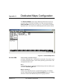
1
NxT1 HSSI/V.35 Module
User Manual
Part Number 1200771L1
61200771L1-1A
March 2002
901 Explorer Boulevard
P.O. Box 140000
Huntsville, AL 35814-4000
(256) 963-8000
© 2002 ADTRAN, Inc.
All Rights Reserved.
Printed in U.S.A.
Notes provide additional useful information.
Cautions signify information that could prevent service interruption.
Warnings provide information that could prevent damage to the equipment or
endangerment to human life.
Safety Instructions
When using your telephone equipment, please follow these basic safety precautions to reduce the risk
of fire, electrical shock, or personal injury:
1. Do not use this product near water, such as a bathtub, wash bowl, kitchen sink, laundry tub, in
a wet basement, or near a swimming pool.
2. Avoid using a telephone (other than a cordless-type) during an electrical storm. There is a
remote risk of shock from lightning.
3. Do not use the telephone to report a gas leak in the vicinity of the leak.
4. Use only the power cord, power supply, and/or batteries indicated in the manual. Do not
dispose of batteries in a fire. They may explode. Check with local codes for special disposal
instructions.
Save These Important Safety Instructions
3
Affidavit Requirements for Connection to Digital Services
•
•
•
An affidavit is required to be given to the telephone company whenever digital terminal equipment
without encoded analog content and billing protection is used to transmit digital signals containing
encoded analog content which are intended for eventual conversion into voiceband analog signals
and transmitted on the network.
The affidavit shall affirm that either no encoded analog content or billing information is being
transmitted or that the output of the device meets Part 68 encoded analog content or billing
protection specifications.
End user/customer will be responsible for filing an affidavit with the local exchange carrier when
connecting unprotected customer premise equipment (CPE) to 1.544 Mbps or subrate digital
services.
Until such time as subrate digital terminal equipment is registered for voice applications, the affidavit
requirement for subrate services is waived.
4
Affidavit for Connection of Customer Premises Equipment
to 1.544 Mbps and/or Subrate Digital Services
For the work to be performed in the certified territory of ___________________ (telco name)
State of ________________
County of ________________
I, _______________________ (name), ____________________________________ (business
address),
____________________ (telephone number) being duly sworn, state:
I have responsibility for the operation and maintenance of the terminal equipment to be
connected to 1.544 Mbps and/or ________ subrate digital services. The terminal equipment to be
connected complies with Part 68 of the FCC rules except for the encoded analog content and
billing protection specifications. With respect to encoded analog content and billing protection:
( ) I attest that all operations associated with the establishment, maintenance, and adjustment of the
digital CPE with respect to analog content and encoded billing protection information
continuously complies with Part 68 of the FCC Rules and Regulations.
( ) The digital CPE does not transmit digital signals containing encoded analog content or billing
information which is intended to be decoded within the telecommunications network.
( ) The encoded analog content and billing protection is factory set and is not under the control of the
customer.
I attest that the operator(s)/maintainer(s) of the digital CPE responsible for the establishment,
maintenance, and adjustment of the encoded analog content and billing information has (have)
been trained to perform these functions by successfully having completed one of the following
(check appropriate blocks):
( ) A. A training course provided by the manufacturer/grantee of the equipment used to encode
analog signals; or
( ) B. A training course provided by the customer or authorized representative, using training
materials and instructions provided by the manufacturer/grantee of the equipment used to
encode analog signals; or
( ) C. An independent training course (e.g., trade school or technical institution) recognized by the
manufacturer/grantee of the equipment used to encode analog signals; or
( ) D. In lieu of the preceding training requirements, the operator(s)/maintainer(s) is (are) under the
control of a supervisor trained in accordance with _________ (circle one) above.
5
I agree to provide ______________________ (telco’s name) with proper documentation to
demonstrate compliance with the information as provided in the preceding paragraph, if so
requested.
_________________________________Signature
_________________________________Title
_________________________________ Date
Transcribed and sworn to before me
This ________ day of _______________, _______
_________________________________
Notary Public
My commission expires:
_________________________________
6
FCC regulations require that the following information be provided in this manual:
1. This equipment complies with Part 68 of FCC rules. On the back of the equipment housing is
a label showing the FCC registration number and ringer equivalence number (REN). If
requested, provide this information to the telephone company.
2. If this equipment causes harm to the telephone network, the telephone company may
temporarily discontinue service. If possible, advance notification is given; otherwise,
notification is given as soon as possible. The telephone company will advise the customer of
the right to file a complaint with the FCC.
3. The telephone company may make changes in its facilities, equipment, operations, or
procedures that could affect the proper operation of this equipment. Advance notification and
the opportunity to maintain uninterrupted service are given.
4. If experiencing difficulty with this equipment, please contact ADTRAN for repair and
warranty information. The telephone company may require this equipment to be disconnected
from the network until the problem is corrected or it is certain the equipment is not
malfunctioning.
5. This unit contains no user-serviceable parts.
6. An FCC compliant telephone cord with a modular plug is provided with this equipment. This
equipment is designed to be connected to the telephone network or premises wiring using an
FCC compatible modular jack, which is Part 68 compliant.
7. The following information may be required when applying to the local telephone company for
leased line facilities:
Service Type
SOC
REN
FIC
USOC
1.544 Mbps–SF
04DU9.BN
N/A
6.0N
RJ-48C
SF and B8ZS
04DU9.DN
ESF
04DU9.1KN
ESF and B8ZS
04DU9.1SN
8. The REN is useful in determining the quantity of devices you may connect to your telephone
line and still have all of those devices ring when your number is called. In most areas, the sum
of the RENs of all devices should not exceed five. To be certain of the number of devices you
may connect to your line as determined by the REN, call your telephone company to
determine the maximum REN for your calling area.
9. This equipment may not be used on coin service provided by the telephone company.
Connection to party lines is subject to state tariffs. Contact your state public utility
commission or corporation commission for information.
7
Federal Communications Commission Radio Frequency Interference Statement
This equipment has been tested and found to comply with the limits for a Class A digital device,
pursuant to Part 15 of the FCC Rules. These limits are designed to provide reasonable protection
against harmful interference when the equipment is operated in a commercial environment. This
equipment generates, uses, and can radiate radio frequency energy and, if not installed and used in
accordance with the instruction manual, may cause harmful interference to radio frequencies.
Operation of this equipment in a residential area is likely to cause harmful interference in which case
the user will be required to correct the interference at his own expense.
Changes or modifications to this unit not expressly approved by the party
responsible for compliance could void the user’s authority to operate the equipment.
8
Industry Canada Compliance Information
Notice: The Industry Canada label applied to the product (identified by the Industry Canada logo or the
“IC:” in front of the certification/registration number) signifies that the Industry Canada technical
specifications were met.
Notice: The Ringer Equivalence Number (REN) for this terminal equipment is supplied in the
documentation or on the product labeling/markings. The REN assigned to each terminal device
indicates the maximum number of terminals that can be connected to a telephone interface. The
termination on an interface may consist of any combination of devices subject only to the requirement
that the sum of the RENs of all the devices should not exceed five (5).
Canadian Emissions Requirements
This digital apparatus does not exceed the Class A limits for radio noise emissions from digital
apparatus as set out in the interference-causing equipment standard entitled “Digital Apparatus,”
ICES-003 of the Department of Communications.
Cet appareil nuerique respecte les limites de bruits radioelectriques applicables aux appareils
numeriques de Class A prescrites dans la norme sur le materiel brouilleur: “Appareils Numeriques,”
NMB-003 edictee par le ministre des Communications.
9
Warranty and Customer Service
ADTRAN will replace or repair this product within five years from the date of shipment if it does not
meet its published specifications or fails while in service. For detailed warranty, repair, and return
information refer to the ADTRAN Equipment Warranty and Repair and Return Policy Procedure.
Return Material Authorization (RMA) is required prior to returning equipment to ADTRAN.
For service, RMA requests, or further information, contact one of the numbers listed at the end of this
section.
LIMITED PRODUCT WARRANTY
ADTRAN warrants that for five years from the date of shipment to Customer, all products
manufactured by ADTRAN will be free from defects in materials and workmanship. ADTRAN also
warrants that products will conform to the applicable specifications and drawings for such products, as
contained in the Product Manual or in ADTRAN's internal specifications and drawings for such
products (which may or may not be reflected in the Product Manual). This warranty only applies if
Customer gives ADTRAN written notice of defects during the warranty period. Upon such notice,
ADTRAN will, at its option, either repair or replace the defective item. If ADTRAN is unable, in a
reasonable time, to repair or replace any equipment to a condition as warranted, Customer is entitled to
a full refund of the purchase price upon return of the equipment to ADTRAN. This warranty applies
only to the original purchaser and is not transferable without ADTRAN's express written permission.
This warranty becomes null and void if Customer modifies or alters the equipment in any way, other
than as specifically authorized by ADTRAN.
EXCEPT FOR THE LIMITED WARRANTY DESCRIBED ABOVE, THE FOREGOING
CONSTITUTES THE SOLE AND EXCLUSIVE REMEDY OF THE CUSTOMER AND THE
EXCLUSIVE LIABILITY OF ADTRAN AND IS IN LIEU OF ANY AND ALL OTHER
WARRANTIES (EXPRESSED OR IMPLIED). ADTRAN SPECIFICALLY DISCLAIMS ALL
OTHER WARRANTIES, INCLUDING (WITHOUT LIMITATION), ALL WARRANTIES OF
MERCHANTABILITY AND FITNESS FOR A PARTICULAR PURPOSE. SOME STATES DO
NOT ALLOW THE EXCLUSION OF IMPLIED WARRANTIES, SO THIS EXCLUSION MAY
NOT APPLY TO CUSTOMER.
In no event will ADTRAN or its suppliers be liable to Customer for any incidental, special, punitive,
exemplary or consequential damages experienced by either Customer or a third party (including, but
not limited to, loss of data or information, loss of profits, or loss of use). ADTRAN is not liable for
damages for any cause whatsoever (whether based in contract, tort, or otherwise) in excess of the
amount paid for the item. Some states do not allow the limitation or exclusion of liability for incidental
or consequential damages, so the above limitation or exclusion may not apply to Customer.
10
Customer Service, Product Support Information, and Training
ADTRAN will repair and return this product if within five years from the date of shipment the product
does not meet its published specification or the product fails while in service.
A return material authorization (RMA) is required prior to returning equipment to ADTRAN. For
service, RMA requests, training, or more information, use the contact information given below.
Repair and Return
If you determine that a repair is needed, please contact our Customer and Product Service (CAPS)
department to have an RMA number issued. CAPS should also be contacted to obtain information
regarding equipment currently in house or possible fees associated with repair.
CAPS Department
(256) 963-8722
Identify the RMA number clearly on the package (below address), and return to the following address:
ADTRAN Customer and Product Service
901 Explorer Blvd. (East Tower)
Huntsville, Alabama 35806
RMA # _____________
Pre-Sales Inquiries and Applications Support
Your reseller should serve as the first point of contact for support. If additional pre-sales support is
needed, the ADTRAN Support web site provides a variety of support services such as a searchable
knowledge base, latest product documentation, application briefs, case studies, and a link to submit a
question to an Applications Engineer. All of this, and more, is available at:
http://support.adtran.com
When needed, further pre-sales assistance is available by calling our Applications Engineering
Department.
Applications Engineering (800) 615-1176
11
Post-Sale Support
Your reseller should serve as the first point of contact for support. If additional support is needed, the
ADTRAN Support web site provides a variety of support services such as a searchable knowledge
base, updated firmware releases, latest product documentation, service request ticket generation and
trouble-shooting tools. All of this, and more, is available at:
http://support.adtran.com
When needed, further pre-sales assistance is available by calling our Technical Support Center. Please
have your unit serial number available when you call.
Technical Support
(888) 4ADTRAN
Installation and Maintenance Support
The ADTRAN Custom Extended Services (ACES) program offers multiple types and levels of
installation and maintenance services which allow you to choose the kind of assistance you need. This
support is available at:
http://www.adtran.com/aces
For questions, call the ACES Help Desk.
ACES Help Desk
(888) 874-ACES (2237)
Training
The Enterprise Network (EN) Technical Training Department offers training on our most popular
products. These courses include overviews on product features and functions while covering
applications of ADTRAN's product lines. ADTRAN provides a variety of training options, including
customized training and courses taught at our facilities or at your site. For more information about
training, please contact your Territory Manager or the Enterprise Training Coordinator.
12
Training Phone
(800) 615-1176, ext. 7500
Training Fax
(256) 963-6700
Training Email
[email protected]
Table of Contents
List of Tables.......................................................................................................................................................15
List of Figures .....................................................................................................................................................17
Chapter 1
Introduction................................................................................................................................19
NxT1 HSSI/V.35 Module Overview ................................................................................................................19
Functional Description .......................................................................................................................................20
Features ................................................................................................................................................................20
NxT1 HSSI/V.35 Module Specifications .........................................................................................................20
Physical Description ...........................................................................................................................................22
Chapter 2
Installation..................................................................................................................................23
Before Installing the NxT1 HSSI/V.35 Module ..............................................................................................23
Shipping Contents .......................................................................................................................................23
Installing the NxT1 HSSI/V.35 Module ..........................................................................................................24
Wiring ...................................................................................................................................................................25
Power Up and Initialization ..............................................................................................................................26
Failed Self-Test .............................................................................................................................................26
Operation Alarms ........................................................................................................................................26
Chapter 3
Operation ....................................................................................................................................27
Overview ..............................................................................................................................................................27
Terminal Menu Structure...................................................................................................................................27
Modules ................................................................................................................................................................28
Slt ...................................................................................................................................................................29
Type ..............................................................................................................................................................29
Menu .............................................................................................................................................................30
Alarm ............................................................................................................................................................30
Test ................................................................................................................................................................30
State ...............................................................................................................................................................30
Status ............................................................................................................................................................30
Online ....................................................................................................................................................30
No Response .........................................................................................................................................30
Empty ....................................................................................................................................................31
Offline ....................................................................................................................................................31
Offline/No Response ..........................................................................................................................31
Rev ................................................................................................................................................................31
Modules/Menu ...................................................................................................................................................31
NxT1 HSSI
Option Module ............................................................................................................................................32
Info .........................................................................................................................................................32
T1 Enable ...............................................................................................................................................32
61200771L1-1
NxT1 HSSI/V.35 User Manual
13
Table of Contents
T1 Menus .............................................................................................................................................. 33
IMUX Menus ....................................................................................................................................... 35
HSSI Menus ......................................................................................................................................... 36
ATLAS Features Used with NxT1 HSSI/V.35 Module Options ................................................................. 39
Factory Restore ................................................................................................................................................... 39
Run Selftest.......................................................................................................................................................... 39
Appendix A Dedicated Maps Configuration............................................................................................. 41
Auto ...................................................................................................................................................... 41
Maps 1 through 5 ................................................................................................................................ 41
# ............................................................................................................................................................. 42
Map Name ........................................................................................................................................... 42
Sort To/From ....................................................................................................................................... 42
Connects ............................................................................................................................................... 42
Activate Time ...................................................................................................................................... 43
Enbl Day ............................................................................................................................................... 43
To/From Config .................................................................................................................................. 44
Index .................................................................................................................................................................... 47
14
NxT1 HSSI/V.35 User Manual
61200771L1-1
List of Tables
Table 2-1.
Table 2-2.
Table 3-1.
T1 Pinout Connection ...................................................................................................................25
HSSI/V.35 (SCSI-50) Pinout ........................................................................................................25
Menu Tree for NxT1 HSSI/V.35 Modules Menu .....................................................................29
61200771L1-1
NxT1 HSSI/V.35 User Manual
15
List of Tables
16
NxT1 HSSI/V.35 User Manual
61200771L1-1
List of Figures
Figure 1-1.
Figure 1-2.
Figure 2-1.
Figure 3-1.
Figure 3-2.
Figure 3-3.
Figure 3-4.
Figure A-1.
NxT1 HSSI/V.35 System ..............................................................................................................19
NxT1 HSSI/V.35 Option Module ...............................................................................................22
Installing the NxT1 HSSI/V.35 Module.....................................................................................24
Modules Menu...............................................................................................................................28
NxT1 HSSI/V.35 Module Menu Options ..................................................................................31
T1 Loopback Test Diagram ..........................................................................................................35
HSSI Interface Loopback Test Diagram .....................................................................................37
Dedicated Maps Menu .................................................................................................................41
61200771L1-1
NxT1 HSSI/V.35 User Manual
17
List of Figures
18
NxT1 HSSI/V.35 User Manual
61200771L1-1
Chapter 1
Introduction
NXT1 HSSI/V.35 MODULE OVERVIEW
The NxT1 HSSI/V.35 Module is a member of the ATLAS 800 family of
integrated access products that supports aggregating point-to-point T1
bandwidth (from 2 to 8 T1s) to a single logical datastream available on the
high speed serial interface (HSSI) of the module. The HSSI interface is
delivered using a standard 50-pin SCSI-II connector. Alternately, an optional
adapter cable may be purchased (ADTRAN P/N 3125I081) to convert the
HSSI interface to a single V.35 interface when needed. When using the
NxT1 HSSI/V.35 Module in a V.35 configuration, up to 4 T1s of aggregated
bandwidth is supported.
The inverse multiplexing capacity of the module accommodates eight
T1s, and the module automatically adjusts the data rate to the HSSI/V.35
port upon loss of one or more T1 circuits. In addition to the HSSI port,
four T1 ports are included on the module itself, while alternate T1 ports
can be provided using other ATLAS 800 T1 or T3 modules. The
NxT1 HSSI/V.35 Module combines with the ATLAS 800 Series base
units (ATLAS 800PLUS and ATLAS 890 only) and other ATLAS modules to
support applications calling for increased point-to-point T1 bandwidth.
Figure 1-1 shows a sample application of the NxT1 HSSI/V.35 Module.
Figure 1-1. NxT1 HSSI/V.35 System
61200771L1-1
NxT1 HSSI/V.35 Module User Manual
19
Chapter 1. Introduction
When combined with the supported ATLAS 800 Series base units and,
optionally, one or more Quad T1/PRI or T3 Modules, the NxT1 HSSI/V.35
Module can implement high-speed point-to-point connectivity), combining
multiple T1 circuits into one logical channel on the HSSI/V.35 interface.
FUNCTIONAL DESCRIPTION
The NxT1 HSSI/V.35 Module installs in any available option slot in the
supported ATLAS 800 Series units. You can view the status of the module
itself, as well as the circuits to which it interfaces, from the front panel
(ATLAS 800PLUS only). Additional status information is available via the
terminal menus, accessible through either a VT-100 terminal connected to
the ATLAS 800 Series control port, or via a Telnet session established
through the unit’s Ethernet port. Use the terminal menu to configure the
NxT1 HSSI/V.35 Module and to download application software.
FEATURES
Features of the NxT1 HSSI/V.35 Module are listed here:
•
•
•
•
Standard SCSI-II 50-pin connector for HSSI interface
Optional V.35 interface using adapter cable (ADTRAN P/N 3125I081)
Hot swappable
Maximum distance 6,000 feet (DS-1), 655 feet (DSX-1) when using 24
gauge conductor
NXT1 HSSI/V.35 MODULE SPECIFICATIONS
Each T1 port of the NxT1 HSSI/V.35 Module conforms to the following
specifications:
Line Rate
1.544 Mbps ± 75 bps
Framing
D4, SF or ESF per ANSI t1.403 and AT& T TR 54016
Line Coding
•
•
B8ZS (Bipolar Eight Zero Substitution)
AMI (Alternate Mark Inversion)
Alarms
Loss of Signal (LOS), Red, Yellow, Blue
20
NxT1 HSSI/V.35 Module User Manual
61200771L1-1
Chapter 1. Introduction
Tests
Line or payload loopback (Local and Remote)
Connectors
RJ-48C
The HSSI port of the NxT1 HSSI/V.35 Module conforms to the following
specifications:
Line Rate
Up to 11.04 Mbps
T1 Links
1 to 8 Total T1 Links (in any combination of module T1 interfaces and other
T1/T3 modules)
Connector
50 pin SCSI-II Female
The V.35 interface of the NxT1 HSSI/V.35 Module (using the optional
adapter cable) conforms to the following specifications:
Line Rate
Up to 5.52 Mbps
T1 Links
1 to 4 Total T1 Links (in any combination of module T1 interfaces and other
T1/T3 modules)
Connector
V.35 Winchester
61200771L1-1
NxT1 HSSI/V.35 Module User Manual
21
Chapter 1. Introduction
PHYSICAL DESCRIPTION
The NxT1 HSSI/V.35 Module (see Figure 1-2) plugs into any available
option slot in the rear of the supported ATLAS 800 Series units.
T1-1
T1-2
T1-3
T1-4
HSSI/V.35
NxT1 HSSI/V.35 ATLAS 800 SERIES
Figure 1-2. NxT1 HSSI/V.35 Option Module
The label over each RJ-48C connector refers to the port on the
NxT1 HSSI/V.35 Module.
22
NxT1 HSSI/V.35 Module User Manual
61200771L1-1
Chapter 2
Installation
BEFORE INSTALLING THE NXT1 HSSI/V.35 MODULE
Carefully unpack and inspect the NxT1 HSSI/V.35 Module for shipping
damages. If you suspect damage occurred during shipping, file a claim
immediately with the carrier and then contact ADTRAN Technical
Support (see the front pages of this manual for pertinent information).
If possible, keep the original shipping container for returning the
NxT1 HSSI/V.35 Module for repair or for verification of shipping damage.
Shipping Contents
The ADTRAN shipment includes the following items:
•
•
•
•
NxT1 HSSI/V.35 Module
NxT1 HSSI/V.35 Module Quick Start Guide
NxT1 HSSI/V.35 Module User Manual (insert into the ATLAS 800
Series User Manual)
Four RJ-48 to RJ-48 cables (6 ft)
An optional SCSI-II to V.35 adapter cable is available (ADTRAN P/N
3125I081) for applications requiring a V.35 interface.
61200771L1-1
NxT1 HSSI/V.35 User Manual
23
Chapter 2. Installation
INSTALLING THE NXT1 HSSI/V.35 MODULE
Figure 2-1 represents the actions required to properly install the
NxT1 HSSI/V.35 Module, as described in the Step/Action table below.
T1-1
T1-2
T1-3
T1-4
HSSI/V.35
800 SERIES
NxT1 HSSI/V.35 ATLAS
Figure 2-1. Installing the NxT1 HSSI/V.35 Module
Instructions for Installing the NxT1 HSSI/V.35 Module
Step
Action
1
Remove the cover plate from the appropriate option slot in the
ATLAS 800 Series chassis rear panel.
2
Slide the NxT1 HSSI/V.35 Module into the option slot until the
module is firmly positioned against the front of the chassis.
3
Secure the thumbscrews at both edges of the module.
4
Connect the cables to the associated device(s).
5
Complete installation of remaining modules and Base Unit as
specified in the Installation chapter of the ATLAS 800 Series
User Manual.
To ensure that the thumbscrews are securely fastened, use a screwdriver to tighten them.
24
NxT1 HSSI/V.35 User Manual
61200771L1-1
Chapter 2. Installation
WIRING
Each module T1 port uses a single RJ-48C jack to connect to a T1 circuit.
Table 2-1 shows the T1 pinout connection. The required wiring connection
follows:
(USOC) RJ-48C
Connector Type
Table 2-1. T1 Pinout Connection
PIN
NAME
DESCRIPTION
1
R1 RXDATA
Receive data from the network ring
2
T1 RXDATA
Receive data from the network tip
3, 6, 7, 8
Unused
n/ a
4
R TXDATA
Send data towards the network ring
5
T TXDATA
Send data towards the network tip
The HSSI/V.35 interface uses a single SCSI-II 50 pin connector with an optional V.35 adapter cable. Table 2-2 shows the SCSI-II connector pinout.
Connector Type
50 pin SCSI-II Female
Table 2-2. HSSI/V.35 (SCSI-50) Pinout
61200771L1-1
PIN (+ side)
PIN (- side)
DIRECTION
1
26
—
HSSI SG - Signal Ground
2
27
O
HSSI RT - Receive Timing
3
28
O
HSSI CA - DCE Available
4
29
O
HSSI RD - Receive Data
5
30
O
HSSI LC - Loopback Circuit C
6
31
O
HSSI ST - Send Timing
7
32
—
HSSI SG - Signal Ground
8
33
I
HSSI TA - DTE Available
9
34
I
HSSI TT - Terminal Timing
10
35
I
HSSI LA - Loopback Circuit A
11
36
I
HSSI SD - Send Data
12
37
I
HSSI LB - Loopback Circuit B
13
38
—
NxT1 HSSI/V.35 User Manual
DESCRIPTION
HSSI SG - Signal Ground
25
Chapter 2. Installation
Table 2-2. HSSI/V.35 (SCSI-50) Pinout (Continued)
PIN (+ side)
PIN (- side)
DIRECTION
DESCRIPTION
—
39
—
Ancillary to DCE (Reserved)
14
—
I
V.35 RTS - Request to Send
15
40
I
V.35 TT Terminal Timing
16
41
I
V.35 SD Send Data
—
42
O
V.35 DCD - Data Carrier Detect
17-18
43
—
Ancillary to DCE (Reserved)
19
44
—
HSSI SG - Signal Ground
20
45
O
V.35 ST - Send Timing
21
46
O
V.35 RT - Receive Timing
22
47
O
V.35 RD - Receive Data
23
—
O
V.35 CTS - Clear to Send
—
48
I
V.35 Ground/Present
24
49
O
HSSI TM - Test Mode
25
50
—
HSSI SG - Signal Ground
POWER UP AND INITIALIZATION
The NxT1 HSSI/V.35 Module requires no initialization input during the
power-up sequence, as described in the ATLAS 800 Series User Manuals.
Any previously configured setting for the NxT1 HSSI/V.35 Module is automatically restored upon power-up.
Failed Self-Test
If the NxT1 HSSI/V.35 Module fails self-test, a message will be displayed
on the LCD and the terminal menu self-test log during power-up. See the
appropriate ATLAS 800 Series User Manual for details.
Operation Alarms
The red ALARM LED (located with the Module LEDs on the front panel)
illuminates when an alarm condition is detected.
26
NxT1 HSSI/V.35 User Manual
61200771L1-1
Chapter 3
Operation
OVERVIEW
You can control and configure the NxT1 HSSI/V.35 Module from a variety
of sources, including the following:
•
•
•
The ATLAS 800 Series front panel, providing minimal configuration
and status support
The terminal menus, allowing detailed configuration, status, and diagnostics
SNMP, primarily for reporting alarm conditions and system status
The remainder of this section describes the menu items presented when managing the NxT1 HSSI/V.35 Module via the terminal menu.
Access the terminal menu using either a VT-100 terminal attached to the
ATLAS 800 Series Base Unit’s control port or a Telnet session established
through the Base Unit’s Ethernet port. The ATLAS 800 Series User Manual
provides detailed instructions on the operation of each of these management
approaches.
To edit items in the terminal menu, you must have the appropriate password level. Each menu
description in this section indicates the password level required for write and read access. See
“Access Passwords” in the appropriate ATLAS 800 Series User Manual for detailed
information on working with passwords. Security level 0 users can view and edit every available
field. Security level 5 users can view any field but cannot edit.
TERMINAL MENU STRUCTURE
ATLAS 800 Series uses a hierarchical menu structure to provide access to
all of its features. The top-most menu level leads to submenus which are
grouped by functionality. All menu items display in the terminal window. To
access the NxT1 HSSI/V.35 Module, activate the MODULES menu. The following sections describe the menu items for the MODULES menu.
Refer to the appropriate ATLAS 800 Series User Manual for detailed instructions on
navigating through the terminal menu.
61200771L1-1
NxT1 HSSI/V.35 Module User Manual
27
Chapter 3. Operation
MODULES
The ATLAS 800 Series system controller automatically detects the presence
of the NxT1 HSSI/V.35 Module when it is installed in the system. To see the
menus for the NxT1 HSSI/V.35 Module via the terminal menu, use the arrow
keys to scroll to the Modules menu and press ENTER to access the module
choices. Figure 3-1 shows the Modules menu (see also the menu tree in
Table 3-1 on page 29). The following sections describe all the Modules’
menu options.
Figure 3-1. Modules Menu
28
NxT1 HSSI/V.35 Module User Manual
61200771L1-1
Chapter 3. Operation
Part Number
Serial Number
Info
Assembly Revision
Firmware Revision
Prt
T1 Enable
Enabled
CLR
Disabled
Slt
NxT1 HSSI Menus
Type
Alarm Status
Menu
LOS
ES
Prt
RED
BES
Alarms
YELLOW
SES
Rx Level
BLUE
SEFS
DS0 Alarm
LOFC
Modules Alarm
Test
CSS
State
T1 Menus*
Performance (Curr, 15Min, 24Hr)
UAS
Rev
LCV
Config
Module Alarms
Prt
PCV
Port Name
LES
Frame
Code
Test
IMUX Menus
Config
Prt
Tx Yel
Loc LB
LBO
Prt
Grp Assoc
Scramble
Loopback
Status
LA
HSSI Menus
LB
Config
Tx Clk
TA
CA
Rx Rate
LC
Tx Rate
*The T1 menus are only visible when T1 Enable is set to Enabled.
Table 3-1. Menu Tree for NxT1 HSSI/V.35 Modules Menu
SLT
Read security: 5
Displays the number of the available slots in the ATLAS 800 Series chassis.
Slot 0 refers to the ATLAS 800 Series unit. This field is read-only.
TYPE
Write security: 3; Read security: 5
Displays the type of module actually installed in the slot or the type of module you plan to install in the slot. If an NxT1 HSSI/V.35 Module is installed,
the Type field automatically defaults to NXT1 HSSI (the NxT1 HSSI/V.35
Module). You can use this field to preconfigure a system before actually
61200771L1-1
NxT1 HSSI/V.35 Module User Manual
29
Chapter 3. Operation
installing modules by simply specifying the module that you want to install
in each slot.
TYPE automatically displays the name of an installed module. If you want to change this field to
a different type of module, you must set TYPE to EMPTY before selecting the other module.
MENU
Displays additional status and configuration menus for the selected
module. (To access the submenus for this item, use the arrow keys to
scroll to the MENU column for the module you want to edit, and press
Enter.) For detailed information on each submenu item, see the section
Modules/Menu on page 31.
ALARM
Read security: 5
Displays an alarm condition on the NxT1 HSSI/V.35 Module. Press Enter in
this field to activate the menu.
TEST
Read security: 5
Displays test name if the NxT1 HSSI/V.35 Module is executing a test. Press
Enter in this field to activate the menu.
STATE
Displays module status as either ONLINE of OFFLINE. Even though a module
is physically installed, it must be marked as online for it to be considered an
available resource. This field allows an installed module to be marked as offline, which may be useful in system troubleshooting. If you choose OFFLINE,
the module will not be in alarm condition, but will display OFFLINE.
Once a module is installed, STATE must be set to ONLINE in order for the ATLAS 800 Series unit
to use the module for any data bandwidth.
STATUS
30
This read-only field provides status information on the NxT1 HSSI/V.35
Module. The following messages may display:
ONLINE
The module is enabled, and is responding to the system controller’s status
polls. This is the normal response of the system.
NO RESPONSE
The module is enabled, but is not responding to the system controller’s status
polls. This response indicates either a problem in the system or that the module is not installed.
NxT1 HSSI/V.35 Module User Manual
61200771L1-1
Chapter 3. Operation
EMPTY
The system controller has not detected the presence of a module in the slot,
nor has a module been manually enabled for this option slot.
OFFLINE
The module is installed, but has been taken offline by a user. The module is
still responding to controller polls.
OFFLINE/NO
RESPONSE
The module is installed, but has been taken offline by a user. The module is
not responding to polls.
REV
This read-only field displays the hardware revision of the NxT1 HSSI/V.35
Module.
MODULES/MENU
Figure 3-2 shows the menu options available for the NxT1 HSSI/V.35 Module (see also the menu tree in Table 3-1 on page 29). The following sections
describe these options.
Figure 3-2. NxT1 HSSI/V.35 Module Menu Options
61200771L1-1
NxT1 HSSI/V.35 Module User Manual
31
Chapter 3. Operation
NXT1 HSSI
OPTION MODULE
The NxT1 HSSI/V.35 Module system controller automatically detects the
presence of the NxT1 HSSI Option Module when it is installed in the system
(listed as NXT1 HSSI). To see the menus for the NxT1 HSSI Option Module
via the terminal menu, use the arrow keys to scroll to the MODULES menu
and press <Enter> to access the module choices. V.35 is available when using the optional adapter cable (ADTRAN P/N 3125I081). Some of the following menus do not apply when configured for V.35 mode.
Read security: 5
INFO
Provides information about the module part number, serial number and assembly revision.
PART NUMBER
Read security: 5
Displays the part number of the module.
SERIAL NUMBER
Read security: 5
Displays the serial number of the module.
ASSEMBLY REVISION
Read security: 5
Displays the assembly revision.
FIRMWARE REVISION
Read security: 5
Displays the current firmware revision of the NxT1 HSSI Option Module.
T1 ENABLE
Write Security: 3; Read Security: 5
Configures the NxT1 HSSI Option Module to activate the module’s four
built-inT1 interfaces. When configuring the module to use more than four
T1s from other installed T1/T3 modules, this field should be set to
DISABLED.
The NxT1 HSSI/V.35 Module’s four built-in T1 interfaces are activated collectively as a bundle.
Setting the T1 ENABLE menu to ENABLED allows you to map from any/all of the built-in T1
ports to the HSSI interface. Setting the T1 ENABLE menu to DISABLED requires ALL of the T1s
mapped to the HSSI interface to be from other installed T1/T3 modules.
32
NxT1 HSSI/V.35 Module User Manual
61200771L1-1
Chapter 3. Operation
T1 MENUS
Read Security: 5
Provides information about the four T1 interfaces located on the NxT1
HSSI Option Module. This menu is only visible when T1 ENABLE is set to
ENABLED.
ALARMS
Read security: 5
Displays an alarm condition on the ATLAS 550 unit. Press <Enter> to
access this menu item.
LOS
Indicates a loss of signal detected on port interface.
RED
Indicates inability to frame data received on the port. Alternately
referred to as Out of Frame (OOF).
YELLOW
Receiving remote alarm (RAI) on port.
BLUE
Receiving unframed all ones from the port Alarm Indicator Signal
(AIS).
DS0 ALARM
Displays per-DS0 alarm status; that is, at least one DS0 channel is
in alarm if an asterisk (*) appears. These alarms usually indicate the
failure to receive the protocol that has been configured for the DS0.
RX LEVEL
(Receive Level) Indicates the strength of the signal (in dB) received
on the port.
PERFORMANCE
Write security: 3; Read security: 5
The performance fields (either current, 15-minute total, or 24-hour total)
provide status on key performance measures as specified in ANSI T1.403
and AT&T TR54016 for the T1/PRI port. All fields except CLR are readonly. The monitored parameters include the following:
PRT
Displays the port number
CLR
Clears performance information for the selected port
ES
Errored Second (ES) is a second with one or more error events OR
one or more Out Of Frame events OR one or more Controlled Slips
BES
Bursty Errored Second (BES) is a second with more than one, but
less than 320 error events
61200771L1-1
NxT1 HSSI/V.35 Module User Manual
33
Chapter 3. Operation
SES
Severely Errored Second (SES) is a second with 320 or more error
events OR one or more Out Of Frame events
SEFS
Severely Errored Frame Second is a second that contains four consecutive errored framing patterns.
LOFC
Loss of Frame Count is a count of seconds in which a valid framing
pattern could not be obtained.
CSS
Controlled Slip Second
UAS
Unavailable Second
LCV
Line Code Violation
PCV
Path Code Violation
LES
Line Errored Second
CONFIGURATION
Write security: 3; Read security: 5
All of the following configurable parameters apply to whether the port is
connected to a Primary Rate ISDN circuit or a channelized T1 circuit.
PRT
Displays the port number.
PORT NAME
Accepts any alpha-numeric name up to 16 characters long, to
uniquely identify each port on the NxT1 HSSI/V.35 Module.
FRAME
Write security: 2; Read security: 5
This field must be set to match the frame format of the circuit to
which it is connected, available from the network supplier. Choose
either D4 or ESF.
CODE
Write security: 2; Read security: 5
Set this field to match the line code of the circuit to which it is connected (this information is available from the network supplier).
Choose either AMI or B8ZS.
TX YEL
Controls the transmitting of yellow alarms. Choose either ON or
OFF.
34
NxT1 HSSI/V.35 Module User Manual
61200771L1-1
Chapter 3. Operation
TX PRM
Controls the sending of performance report messaging (PRM) data
on the facility data link (FDL). The PRM data continues to be collected even if XMIT PRM is turned off (possible only with ESF format). Choose either ON or OFF.
LBO
Write security: 2; Read security: 5
Selects the Line Build Out (LBO) for the network interface. The
LBO setting determines the amplitude of the transmitted signal.
For short haul (intra-building) applications, choose from the ft
options. For long haul (out of plant) applications, choose from the
dB options. When you select this item, a list of choices displays.
Select the appropriate option.
TEST
Write security: 3; Read security: 5
These options initiate different types of tests and display test results.
PRT
Displays the port number.
LOC LB
Write security: 4; Read security: 5
Causes loopback on near-end (local) port (see Figure 3-3). The following options are available:
LINE
Metallic loopback
PAYLD
Payload loopback - framing and
clocking are regenerated
T1 Port
NI CSU
DS1
Payload Loopback
Line Loopback
Figure 3-3. T1 Loopback Test Diagram
IMUX MENUS
61200771L1-1
Read Security: 5
Contains the inverse muxing configuration parameters for the NxT1 HSSI
Option Module.
NxT1 HSSI/V.35 Module User Manual
35
Chapter 3. Operation
CONFIG
Read Security: 5; Write Security: 5
Contains parameters to include T1 data streams to the HSSI interface.
PRT
Displays the port number for the T1s mapped to the NxT1 HSSI
interface. Ports 1 through 4 are the T1 interfaces located on the
NxT1 HSSI Option Module. Ports 5 through 8 are T1s mapped to
the NxT1 HSSI Option Module in the Dedicated Maps.
GROUP ASSOCIATION
Associates T1s (either mapped to this card and/or the on-board T1s)
with the HSSI interface data stream. To add the T1 to the data
stream, select the GROUP1 option.
SCRAMBLE
Enabling the SCRAMBLE option configures the NxT1 HSSI Module
to prevent ones density violations when transmitting ADTRAN
IMUX headers on a T1 circuit with AMI line coding.
Use extreme caution when disabling the SCRAMBLE option. ADTRAN recommends
enabling the SCRAMBLE option for normal use.
HSSI MENUS
Read Security: 5
Provides status, configuration, and testing parameters for the 50-pin SCSIII HSSI interface.
STATUS
Read Security: 5
Displays the current loopback status of the HSSI interface
LOOPBACK
Displays the current loopback status of the HSSI interface. The following loopback options are possible (see Figure 3-4 on page 37):
LOCAL DTE LOOPBACK
A local DTE loopback occurs at the DTE port of the DCE, and is
used to test the link between the DTE and DCE (NxT1HSSI module).
LOCAL LINE LOOPBACK
A local line loopback occurs in the IMUX engine and is used to test
functionality between the DTE and the IMUX engine.
REMOTE LINE LOOPBACK
A remote line loopback occurs at the T1 interface and is used to test
functionality between the DTE and the T1 interfaces.
36
NxT1 HSSI/V.35 Module User Manual
61200771L1-1
Chapter 3. Operation
Remote Line Loopback
Local Line Loopback
Local DTE Loopback
NxT1 HSSI
T1 Interfaces
IMUX
DTE
Figure 3-4. HSSI Interface Loopback Test Diagram
LA AND LB
(Not applicable in V.35 mode.)
Displays the status of the loopback circuit A and B signals. LA and
LB are asserted by the DTE to enable a loopback on the DCE and
its associated data communications channel. Four possible loopback options are available:
LA
LB
Loopback
Off
Off
No Loopback Active
On
On
Local DTE Loopback is Active
On
Off
Local Line Loopback is Active
Off
On
Remote Line Loopback is Active
TA
Displays the status of the data Terminal equipment Available signal.
TA will be asserted by the DTE (independently of CA) when the
DTE is prepared to both send and receive data to and from the
DCE. Valid data transmission should not commence until CA has
also been asserted by the DCE. If the data communications channel
requires a keep alive data pattern when the DTE is disconnected,
then the DCE shall supply this pattern while TA is deasserted.
When using the NxT1 HSSI Module (1200346L2 only) in V.35
mode, TA displays the status of the Request to Send (RTS) signal.
When RTS is active in a V.35 configuration, Clear to Send (CTS) is
also active.
61200771L1-1
NxT1 HSSI/V.35 Module User Manual
37
Chapter 3. Operation
RX RATE AND TX RATE
Displays the current average receive and transmit data rate on the
HSSI interface.
CONFIG
Read Security: 5
Provides configuration parameters for the HSSI interface including data
clocking.
When using the NxT1 HSSI/V35 Module in V.35 mode, Data Set Ready (DSR) and Data
Carrier Detect (DCD) are always active.
TX CLOCK
Controls the clock used by the NxT1 HSSI/V.35 Module to accept
the transmit (TX) data from the DTE. This is usually set to Normal.
If the interface cable is long, causing a phase shift in the data, the
clock can be set to Inverted. This switches the phase of the clock,
which compensates for a long cable.
CA
(Not applicable in V.35 mode.)
Asserts the data Communications equipment Available signal from
the DCE. CA will be asserted by the DCE, independently of TA,
when the DCE is prepared to both send and receive data to and
from the DTE. This indicates that the DCE has obtained a valid data
communications channel. Data transmission should not commence
until TA has also been asserted by the DTE.
LC
(Not applicable in V.35 mode.)
Enables the Loopback Circuit C signal from the DCE. LC is an
optional loopback request signal from the DCE to the DTE,
requesting the DTE provide a loopback path to the DCE.
38
NxT1 HSSI/V.35 Module User Manual
61200771L1-1
Chapter 3. Operation
ATLAS FEATURES USED WITH NXT1 HSSI/V.35 MODULE OPTIONS
Two additional ATLAS 800 Series menu items can operate in conjunction
with the NxT1 HSSI/V.35 Module: FACTORY RESTORE and RUN SELFTEST.
FACTORY
RESTORE
You can restore the factory default settings for an NxT1 HSSI/V.35 Module
by pressing F either while the cursor is over the SLT number (this action restores the factory settings for all of the module options) or while the cursor
is over an individual field (this action restores factory settings only for the
particular field).
RUN SELFTEST
RUN SELFTEST, a submenu of the ATLAS 800 Series main menu item TEST,
executes both the NxT1 HSSI/V.35 Module internal test and the ATLAS 800
Series internal test. For additional information on RUN SELFTEST, see the ATLAS 800 Series User Manual.
When RUN SELFTEST displays, place the cursor on it and press Enter to execute the test. The unit continuously changes the display on the self-test log
screen until all test results are shown.
61200771L1-1
NxT1 HSSI/V.35 Module User Manual
39
Chapter 3. Operation
40
NxT1 HSSI/V.35 Module User Manual
61200771L1-1
Appendix A
Dedicated Maps Configuration
The DEDICATED MAPS menu assigns dedicated connections between any
two ports in the ATLAS 800 Series Base Unit. This section describes the
DEDICATED MAPS menu items (see Figure A-1). These options are moduledependent; that is, the menu items available depend on the module selected.
Figure A-1. Dedicated Maps Menu
ACTIVATE MAP
Write security:3; Read security:5
Activates a dedicated map—automatically or manually. You can have up to
five different dedicated maps, each with an optionally specified name. The
configuration choices are:
AUTO
Automatically activates a particular dedicated map at the time and day specified in the ACTIVATE TIME field.
MAPS 1 THROUGH 5
Allows you to manually activate a specific dedicated map. To manually
activate a dedicated map, highlight the ACTIVATE MAP field, press <Enter>,
and choose the desired dedicated map from the popup menu list.
61200771L1-1
NxT1 HSSI/V.35 User Manual
41
Appendix A. Dedicated Maps Configuration
CURRENT MAP
Read security:5
Displays the name of the currently active dedicated map (read only).
CREATE/EDIT MAPS
Write security:3; Read security:5
Creates new maps and defines settings, as well as edits existing maps. To
add a new map, position the cursor in the index column and press <I>.
NxT1 HSSI/V.35 Module automatically names the maps in the sequence in
which they are created. You can change the names with MAP NAME.
#
Displays the index number of the available maps.
MAP NAME
Write security: 3; Read security: 5
Displays the name of the dedicated map. The name can contain up to 57
alpha-numeric characters, including spaces and special characters. To edit
the name, press <Enter> and type in the new name.
SORT TO/FROM
Write security: 3; Read security: 5
Specifies sort order based on the end points set in CONNECTS/FROM CONFIG and CONNECTS/TO CONFIG. You can also turn OFF this option. The
sort feature is helpful when you are attempting to find a particular connection in a large connection list.
CONNECTS
Enters the dedicated map connections. Press <Enter> to activate the submenus.
Some of the options available in this submenu change depending on the type of modules
selected in the FROM or TO fields. For more information on these submenus, refer to the
individual module discussions in this section.
You must return to DEDICATED MAPS in the MAIN MENU for changes to take effect.
FROM SLT
Write security:3; Read security:5
Specifies the slot to use for the FROM connection. When you select
this option, a list of all of the slots and the modules installed in the
slots displays. Select the appropriate slot and press <Enter>.
PORT
Write security:3; Read security:5
Specifies the port to use for the FROM connection. When you select
this option, a list of ports and module types appears. Select the
appropriate port and module type, and press <Enter>.
42
NxT1 HSSI/V.35 User Manual
61200771L1-1
Appendix A. Dedicated Maps Configuration
TO SLOT
Write security:3; Read security:5
Specifies the slot to use for the second end of a connection. Select
this option, and a list of all of the slots and the modules installed in
the slots displays. Pick the appropriate slot and press <Enter>.
PORT
Write security:3; Read security:5
Specifies the port to use for the second end of a connection. When
you select this option, a list of ports and module types appears.
Select the appropriate port and module type, and press <Enter>.
FROM CONFIG
Write security:3; Read security:5
Specifies the configuration for the FROM connection. The selections displayed in this field are based on the type of module
selected in the FROM SLT option. For detailed information on submenus for a particular module type, please refer to the dedicated
maps menu discussion for the appropriate network, option, or
resource module.
TO CONFIG
Write security:3; Read security:5
Specifies the configuration for the TO connection. The selections
displayed in this field are based on the type of module selected in
the TO SLT option. For detailed information on submenus for a particular module type, please refer to the dedicated maps menu discussion for the appropriate network, option, or resource module.
SIG
Write security:3; Read security:5
Specifies whether the NxT1 HSSI/V.35 Module uses active
Robbed-Bit Signaling (RBS) on the connection. Selecting ON
allows the NxT1 HSSI/V.35 Module to preserve signaling bits
between the two endpoints of the connection. Selecting OFF
ignores the signaling bits of the connection. This selection is automatically set to OFF when RBS does not apply. For example, a T1to-Nx connection is set to OFF.
ACTIVATE TIME
Write security:3; Read security: 5
Sets the time when the map becomes active if you have selected AUTO in
the ACTIVATE MAP field. Enter this time in hh:mm:ss 24-hour format.
ENBL DAY
Security level: 3; Read security: 5
Specifies which days of the week the map is active.
61200771L1-1
NxT1 HSSI/V.35 User Manual
43
Appendix A. Dedicated Maps Configuration
NXT1 HSSI
OPTION MODULE
CONNECTS
Write Security: 3; Read Security: 5
Enters the dedicated map connections. Press <Enter> to activate the submenus.
The NxT1 HSSI/V35 Module supports connects from the module’s four built-in T1 ports as well as
other installed T1/T3 modules. Enabling the built-in ports by setting the T1 ENABLE field to
ENABLED (see T1 ENABLE on page 32) allows only four T1s from other T1/T3 modules to be
mapped to the HSSI interface in addition to the module’s four built-in ports. When the module’s builtin T1 ports are active, only ports 5-8 will be displayed in the available SLOT/PEP field.
TO/FROM CONFIG
Write Security: 3; Read Security: 5
Specifies the configuration for the To/From connection. The following
selection applies to the NxT1 HSSI Option Module when connected to a
port on a T1 Module. This is the only valid application for the NxT1 HSSI
Option Module.
DS0 SELECTION
Defines DS0s for the T1 port. Use this field to define the DS0s for
this connection.
For the NxT1 HSSI Module, any entry in the DS0 selection field that is less than 24 DS0s is
disregarded. The NxT1 HSSI Module requires the use of all 24 DS0s on a T1 for proper
operation.
DS0S AVAILABLE
Indicates which DS0s of the T1 are assigned. DS0 assignment is
based on the following items:
DIGIT 0-9
This DS0 is available. The digit that displays in this field represents the last digit of the DS0 number.
*
This DS0 has been requested for this connection, but the DS0 is
not yet activated for this port.
!
This DS0 is used by this port in this connection and is currently
activated.
S
This DS0 is used in the switched DIAL PLAN.
44
NxT1 HSSI/V.35 User Manual
61200771L1-1
Appendix A. Dedicated Maps Configuration
S
This DS0 is used in the switched DIAL PLAN and conflicts with
this connection.
N
This DS0 is already used in this DEDICATED MAP.
N
This DS0 is already used in this DEDICATED MAP and conflicts
with this connection.
T1 TROUBLE CODE SERVICE
Sets known values in the signaling bits and the data field for outgoing DS0s which are cross-connected to a T1 port experiencing
alarms.
The trunk conditioning process consists of a 2.5 second transmission (indicating call termination), followed by a continuous transmission signaling the final condition as chosen by the user. This
selection is only valid for T1 ports having RBS set to ON.
This option defines to the NxT1 HSSI/V.35 Module the type of signaling being used on the trunk: E&M, LS/GS Network or User,
SW56, or Custom.
T1 TROUBLE CODE VALUE
Displays the Hex value of the 2.5 second pre alarm transmission.
61200771L1-1
NxT1 HSSI/V.35 User Manual
45
Appendix A. Dedicated Maps Configuration
46
NxT1 HSSI/V.35 User Manual
61200771L1-1
Index
A
Menu Tree . . . . . . . . . . . . . . . . . . . . . . . . . . . . . . 29
Accessing the unit . . . . . . . . . . . . . . . . . . . . . . . . 27
Alarms
Operation . . . . . . . . . . . . . . . . . . . . . . . . . . . 26
Application . . . . . . . . . . . . . . . . . . . . . . . . . . . . . 19
D
Dedicated Maps
NxT1 HSSI Module . . . . . . . . . . . . . . . . . . . 44
Overview . . . . . . . . . . . . . . . . . . . . . . . . . . . . 41
P
Physical Description . . . . . . . . . . . . . . . . . . . . . . 22
R
RJ-48C
Pinout . . . . . . . . . . . . . . . . . . . . . . . . . . . . . . . 25
S
Factory Restore . . . . . . . . . . . . . . . . . . . . . . . . . . 39
Features . . . . . . . . . . . . . . . . . . . . . . . . . . . . . . . . 20
Functional Description . . . . . . . . . . . . . . . . . . . . 20
SCSI-II Connector
Pinout . . . . . . . . . . . . . . . . . . . . . . . . . . . . . . . 25
Self-Test
Failed . . . . . . . . . . . . . . . . . . . . . . . . . . . . . . . 26
Performing . . . . . . . . . . . . . . . . . . . . . . . . . . 39
Shipping Contents . . . . . . . . . . . . . . . . . . . . . . . . 23
H
T
F
HSSI Interface
Pinout . . . . . . . . . . . . . . . . . . . . . . . . . . . . . .
HSSI Port
Connector . . . . . . . . . . . . . . . . . . . . . . . . . . .
Line Rate . . . . . . . . . . . . . . . . . . . . . . . . . . . .
T1 Bandwidth . . . . . . . . . . . . . . . . . . . . . . . .
Installation
Diagram . . . . . . . . . . . . . . . . . . . . . . . . . . . . 24
Steps . . . . . . . . . . . . . . . . . . . . . . . . . . . . . . . . 24
Installing the Module . . . . . . . . . . . . . . . . . . . . . 24
T1 Interface
Pinout . . . . . . . . . . . . . . . . . . . . . . . . . . . . . . . 25
T1 Port
Alarms . . . . . . . . . . . . . . . . . . . . . . . . . . . . . . 20
Connectors . . . . . . . . . . . . . . . . . . . . . . . . . . 21
Framing . . . . . . . . . . . . . . . . . . . . . . . . . . . . . 20
Line Coding . . . . . . . . . . . . . . . . . . . . . . . . . 20
Line Rate . . . . . . . . . . . . . . . . . . . . . . . . . . . . 20
Tests . . . . . . . . . . . . . . . . . . . . . . . . . . . . . . . . 21
Terminal Menu
Structure . . . . . . . . . . . . . . . . . . . . . . . . . . . . 27
L
V
Loopback
HSSI Interface Diagram . . . . . . . . . . . . . . . 37
T1 Diagram . . . . . . . . . . . . . . . . . . . . . . . . . . 35
V.35 Interface
Pinout . . . . . . . . . . . . . . . . . . . . . . . . . . . . . . . 25
V.35 Port
Connector . . . . . . . . . . . . . . . . . . . . . . . . . . . 21
Line Rate . . . . . . . . . . . . . . . . . . . . . . . . . . . . 21
T1 Bandwidth . . . . . . . . . . . . . . . . . . . . . . . . 21
25
21
21
21
I
M
Menu
Modules . . . . . . . . . . . . . . . . . . . . . . . . . . . . 28
NxT1 HSSI Modules . . . . . . . . . . . . . . . . . . 31
61200771L1-1
NxT1 HSSI/V.35 User Manual
47
Index
Index-48
NxT1 HSSI/V.35 User Manual
61200771L1-1