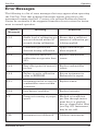
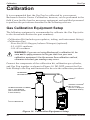
1
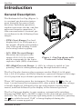
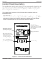
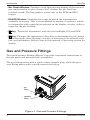
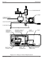
Gas Pup
®
Natural Gas &
Pressure Detection
Instruction 55-9002
Operation & Maintenance
Rev. 1 – December 2003
Product Leadership • Training • Service • Reliability
WARRANTY
Bacharach, Inc. warrants to Buyer that at the time of delivery this Product will be free from defects in material
and manufacture and will conform substantially to Bacharach Inc.’s applicable specifications. Bacharach’s
liability and Buyer’s remedy under this warranty are limited to the repair or replacement, at Bacharach’s
option, of this Product or parts thereof returned to Seller at the factory of manufacture and shown to
Bacharach Inc.’s reasonable satisfaction to have been defective; provided that written notice of the defect
shall have been given by Buyer to Bacharach Inc. within one (1) year after the date of delivery of this Product
by Bacharach, Inc.
Bacharach, Inc. warrants to Buyer that it will convey good title to this Product. Bacharach’s liability and
Buyer’s remedy under this warranty of title are limited to the removal of any title defects or, at the election of
Bacharach, to the replacement of this Product or parts thereof that are defective in title.
THE FOREGOING WARRANTIES ARE EXCLUSIVE AND ARE GIVEN AND ACCEPTED IN LIEU OF (I)
ANY AND ALL OTHER WARRANTIES, EXPRESS OR IMPLIED, INCLUDING WITHOUT LIMITATION THE
IMPLIED WARRANTIES OF MERCHANTABILITY AND FITNESS FOR A PARTICULAR PURPOSE: AND
(II) ANY OBLIGATION, LIABILITY, RIGHT, CLAIM OR REMEDY IN CONTRACT OR TORT, WHETHER OR
NOT ARISING FROM BACHARACH’S NEGLIGENCE, ACTUAL OR IMPLIED. The remedies of the Buyer
shall be limited to those provided herein to the exclusion of any and all other remedies including, without
limitation incidental or consequential damages. No agreement varying or extending the foregoing warranties,
remedies or this limitation will be binding upon Bacharach, Inc. unless in writing, signed by a duly authorized
officer of Bacharach.
To Register Your Warranty, Visit
www.bacharach-inc.com
Declaration of Conformity
Manufacturer’s name:
Bacharach, Inc.
Manufacturer’ address:
621 Hunt Valley Circle
New Kensington, PA 15068-7074
European operations:
Bacharach Europe
Sovereign House, Queensway
Royal Leamington Spa
Warwickshire CV31 3JR
United Kingdom
Product name:
Gas Pup
conforms to the following specifications:
European Directive 89/336/EEC
EN 50081-1: 1992 (Emissions)
EN 50082-1: 1998 (Immunity)
EN 61000-4-2: 1995 (Electromagnet)
EN 61000-4-3: 1995 (Electromagnet)
Notice:
Product improvements and enhancements are continuous, therefore the specifications and information
contained in this document may change without notice.
Bacharach, Inc. shall not be liable for errors contained herein or for incidental or consequential damages in
connection with the furnishing, performance, or use of this material.
No part of this document may be photocopied, reproduced, or translated to another language without the prior
written consent of Bacharach, Inc.
Copyright © 2001-2003, Bacharach, Inc., all rights reserved.
BACHARACH® and Pup® are a registered trademarks of Bacharach, Inc.
All other trademarks, trade names, service marks and logos referenced herein
belong to their respective companies.
A
Instruction 55-9002
Gas Pup
Contents
Contents
Safety Information ....................................................................... iii
Introduction ..................................................................................... 1
General Description ................................................................................ 1
Components ............................................................................................. 2
Natural Gas Detection ....................................................................... 2
Pressure Detection ............................................................................. 2
Sample Pump ..................................................................................... 2
Batteries ............................................................................................. 2
Case ..................................................................................................... 2
Control Panel Description ...................................................................... 3
Gas and Pressure Fittings ...................................................................... 4
Technical Characteristics............................................................. 5
Operation .......................................................................................... 6
Operating Precautions (Please Read) .................................................... 6
Battery Installation ................................................................................. 7
Turning ON the Gas Pup ........................................................................ 8
Turning OFF the Gas Pup .................................................................... 10
Backlighting .......................................................................................... 11
Battery Voltage Check .......................................................................... 11
Gas Operating Mode ............................................................................. 11
Auto-Ranging .................................................................................... 12
Fixed HI% Range .............................................................................. 12
PPM Range ....................................................................................... 13
LO% (Low Percent) Range ............................................................... 13
HI% (High Percent) Range ............................................................... 14
Pressure Operating Mode ..................................................................... 14
Selecting the Pressure Mode ............................................................ 14
High Pressure Mode ......................................................................... 16
Low Pressure Mode .......................................................................... 16
Delta Pressure Mode ........................................................................ 16
Using the Probe’s Filter Chamber ........................................................ 18
Foam Filter Element – Particulate Filtration ................................. 18
Charcoal Filter – Petroleum Vapors vs. Combustible Gases .......... 18
Water/Filter Trap .................................................................................. 20
Error Messages ...................................................................................... 21
Instruction 55-9002
i
Contents
Gas Pup
Calibration ..................................................................................... 22
Gas Calibration Equipment Setup ....................................................... 22
Gas Calibration Procedure ................................................................... 23
Pressure Sensor Check ......................................................................... 27
Maintenance ................................................................................... 28
Batteries ................................................................................................ 28
Sampling Probe ..................................................................................... 28
Gas Inlet Filter Replacement ............................................................... 29
Pump Replacement ............................................................................... 29
Combustibles Sensor Replacement ...................................................... 30
Leak Check Basics ................................................................................ 30
Parts & Service .............................................................................. 32
Replacement Parts ................................................................................ 32
Accessories ............................................................................................. 33
Service Centers ..................................................................................... 34
ii
Instruction 55-9002
Gas Pup
Safety
Safety
Safety is essential in the use and maintenance of Bacharach equipment.
Therefore this manual and any marking on the instrument provide
important safety information concerning the operation, care, and maintenance of this instrument.
All operating and maintenance personnel should read and understand the
contents of this manual before operating or maintaining the instrument.
Observe all of the safety information provided.
Safety Alert Symbol
This symbol together with the word WARNING or CAUTION is used to
call a user’s attention to hazards or unsafe practices that could result in
injury or property damage. The message that follows provides information for preventing or avoiding the hazard.
WARNING: Informs the user of hazards or unsafe practices that
if not avoided could result in severe personal injury or death.
CAUTION: Informs the user of hazards or unsafe practices that
if not avoided could result in personal injury or property damage.
Purpose of Manual
This instruction manual is intended to familiarize all personnel with the
safe operation and maintenance procedures for the Bacharach Gas Pup.
Please retain this manual for future reference.
Instruction 55-9002
iii
Safety
Gas Pup
Notes:
iv
Instruction 55-9002
Gas Pup
Introduction
Introduction
General Description
The Bacharach Gas Pup (Figure 1)
is a natural gas detection instrument designed for general leak
detection, barholing operations,
regulator pressure checks, and line
pressure integrity operations. It
offers measurement of natural gas
(as methane) in the following three
ranges:
• PPM (Low) Range: Gas level
displayed in 0 to 2500 ppm as a
bar graph, allowing visual indication of the peak reading. Useful
for locating leaks in piping.
• LO% (Mid Percent) Range:
Measures natural gas in the
range of 0.2–5.0% by volume,
which corresponds to the lower
explosive limit (LEL) of methane.
Figure 1. Gas Pup shown with
Probe and Coiled Tubing
• HI% (High Percent) Range: 0–100% by volume is useful in “pin
pointing” leaks in underground piping through barhole testing
The Gas Pup also features three pressure modes: High (0 to 99 psig);
Low (–9.9 to 9.9 psig); and Delta (displays a pressure change in the range
of ±9.9 psig from any reference pressure between 0 and 90 psig).
Three ‘AA’ batteries power the instrument. Pressing the
key for at
least 1 second turns the instrument ON; after which, the battery voltage
is briefly displayed, followed by the gas and pressure sensors being
zeroed, and then followed by the display of the detected gas level.
The Gas Pup’s gas display is auto ranging, automatically switching
between its PPM, LO%, and HI% ranges as the detected gas level rises
and falls. The Gas Pup’s pressure-operating mode is selected by pressing
the
key while the word “GAS” is being displayed during the
instrument’s warm-up period.
Instruction 55-9002
1
Introduction
Gas Pup
Components
Natural Gas Detection
The instrument’s PPM and LO% ranges use a catalytic-bead detection
circuit, which is the most widely accepted method of detecting combustible gases. The HI% range uses the thermal-conductivity method of
detection, which is a reliable method for measuring the concentration of
one gas in a second gas (methane in air).
Pressure Detection
The instrument contains a solid-state pressure sensor that supports the
instrument’s three pressure modes (High, Low & Delta). The optional
Pressure Hose Kit accessory with fittings (P/N 55-0038) can be used to
connect the instrument’s quick-connect pressure fitting to the pressure
source.
Sample Pump
An internal sample pump draws a gas sample into the instrument for
analysis. This is a convenience in the LO% and HI% gas ranges, providing
a more reliable and accurate test of gas levels. It is also important in the
PPM range to achieve a stable gas reading at low gas concentrations.
The sample pump includes a flow-failure function. If the flow is blocked
(e.g., clogged filter or crimped hose), the display will blink the letters
“F P” in the READING window. When the pump returns to normal
operation, the display stops blinking.
Batteries
Three ‘AA’ alkaline batteries supply power to the instrument. A fresh set
of batteries will typically last 6–8 hours, depending on how the instrument is used. The batteries are housed in a battery block internal to the
instrument, and are protected with a metal cover and retained by two
thumbscrews. This design allows the batteries to be quickly replaced in
an area known not to contain explosive gases.
Case
The instrument is housed in an anodized extruded aluminum case. The
instrument is rugged, resistant to water and electromagnetic interference. Rubber-bumper guards provide impact protection on both ends of
the instrument.
2
Instruction 55-9002
Introduction
Gas Pup
Control Panel Description
Two pushbutton controls and a large LCD are conveniently located at the
top of the instrument. The backlit LCD provides highly readable indications of natural gas or pressure in any lighting condition ranging from
direct sunlight to total darkness.
The control panel consists of the following three windows and two
pushbutton keys:
• READING Window: A two-digit display that is used to primarily display
the concentration of natural gas in the LO% and HI% gas ranges. The
READING window also displays pressure readings when the instrument is operating in any one of its three pressure modes.
RANGE Window
(range pointer showing
that instrument is in its
HI% range)
READING Window
(showing 25% gas)
Range Identifiers
Bar Graph Window
(active only in the HI%
and ppm ranges,
showing 25% gas)
Power ON/OFF Key,
plus Backlight ON/OFF
Function Key
Figure 2. Controls and Indicators
Instruction 55-9002
3
Introduction
Gas Pup
• Bar Graph Window: Provides a real time moving display of the natural
gas concentration to give a better ‘feel’ of when the gas level has
reached a peak. The bar graph is active only in the PPM and HI%
ranges.
• RANGE Window: Identifies the range in which the instrument is
currently operating. This is accomplished by means of a pointer, which
in conjunction with range-labels printed on the display overlay, define a
range for the gas reading.
•
Key: Turns the instrument, and also the backlight, ON and OFF.
•
Key: Changes the instrument’s function as determined by its current
operating mode, thus allowing a variety of functions to be selected with
just one pushbutton. Refer to text in this manual’s Operating section for
details.
Gas and Pressure Fittings
Two quick-connect fittings (Figure 3) provide convenient connections to
the gas probe and pressure hose assemblies.
The gas fitting mates with a quick-connect female plug, while the pressure fitting mates with a quick-connect male plug.
Gas
Fitting
Pressure
Fitting
Figure 3. Gas and Pressure Fittings
4
Instruction 55-9002
Gas Pup
Technical Characteristics
Technical Characteristics
Measurement Ranges:
Natural Gas ........................... PPM: 0 to 2500 ppm
LO%: 0.2 to 5.0% volume gas
HI%: 0 to 100% volume gas
Pressure:
High .................................... 0 to 99 psig
Low ...................................... ±9.9 psig referenced to atmospheric
pressure
Delta .................................... ±9.9 psig from any reference pressure
point between 0 and 90 psig
Accuracy:
Natural Gas ........................... PPM: (not applicable)
LO%: ±0.3% gas
HI%: ±3% gas
Pressure: ................................ ±5% of Reading
Warm Up Time ........................ 1 minute
Response Time:
Gas.......................................... <20 seconds to 95% of final value
Pressure ................................. <5 seconds to 95% of final value
Operating Environmental Conditions:
Temperature .......................... –4 to 122 °F (–20 to 50 °C)
Humidity ................................ 10 to 95% R.H. (non-condensing)
Air Pressure ........................... 1 Standard Atmosphere, ±10%
Position .................................. Any
Storage Environmental Conditions:
Temperature .......................... –22 to 122 °F (–30 to 50 °C)
Humidity ................................ 10 to 95% R.H. (non-condensing)
Position .................................. Any
Size ............................................ 4.7 x 2.3 x 3.7 in. (11.9 x 5.8 x 9.4 cm)
Weight ...................................... 25 oz (712 g)
Batteries .................................. Qty 3, ‘AA’ alkaline
Battery Life ............................. Typically 6–8 hours of continuous operation, and well over a week of operation
when used from 50 to 60 minutes a day
Agency Approvals ................. MET lab certified to UL913 and CSA
C22.2-157, intrinsically safe for use in
Class I, Division 1, Groups A, B, C & D
hazardous areas
Instruction 55-9002
5
Operation
Gas Pup
Operation
Operating Precautions
(Please Read)
To ensure that the gas sensor is properly zeroed at startup, the Gas Pup
must be turned on in fresh air (free of combustible gases or vapors).
Before using the Pup to detect gas, ‘bump test’ the instrument by applying a known concentration of gas to the instrument’s gas inlet port, and
then observing that the instrument responds to the applied gas in a
positive manner. The optional Response Check Gas bottle (P/N 51-1816) is
recommended for this purpose.
Calibrate the instrument about every 30 days to assure its accuracy. The
frequency of calibration, however, may change depending on how often
the instrument is used and the amount of gas that was sampled. Create a
maintenance log to keep track of when an instrument was calibrated, and
then use this log to help develop a calibration schedule. For example, an
instrument that fails its calibration after only being calibrated a single
time should be calibrated more often.
Avoid sampling leaded gasoline vapors, or gases or vapors containing
silicones or sulfur compounds. Tetraethyl lead, silicones, and sulfur
compounds can form contaminating compounds on the sensor element
(poison the sensor), with resulting loss in sensitivity.
Always purge the instrument with fresh air after completing a test. This
removes combustibles from the sensor chamber and prolongs the life of
the sensor.
6
Instruction 55-9002
Operation
Gas Pup
Battery Installation
WARNING: Explosion hazard:
• To reduce the risk of igniting a flammable atmosphere,
batteries must only be changed in an area known to be
non-flammable.
• To maintain agency approval, use only the following types of
‘AA’ alkaline batteries: Energizer E91; Duracell MN1500 or
MX1500; Rayovac 815; and Panasonic AM-3PI.
1. Loosen the two thumbscrews on battery cover and remove cover.
2. Insert three ‘AA’ batteries into the Pup, observing polarity as shown
in Figure 4.
3. Reinstall battery cover and tighten its thumbscrews.
LOOSEN BOTH BATTERY
COVER THUMBSCREWS
‘AA’ BATTERIES
Figure 4. Battery Installation
Instruction 55-9002
7
Operation
Gas Pup
Turning ON the Gas Pup
Important! To assure that all detectors are properly zeroed, the
Gas Pup must be turned on in a gas-free environment (no
combustibles), and that no pressure is being applied to the
instrument’s pressure port.
It is also recommended that the probe and hose assembly be
connected to the instrument before turning it on.
Refer to Figure 5. The Gas Pup is turned ON by momentarily pressing the
key for 1 second. Listen for the pump to start and observe that all
segments of the display are momentarily turned on. After all segments
have been displayed the word “UEr” (Version) is displayed followed by the
instrument’s software version number. Next, the letter “b” appears in the
RANGE window along with the battery voltage momentarily appearing in
the READING window. The instrument will quickly move to display the
word “GAS”, indicating that the instrument is operating in its gas mode.
After several seconds, the READING window will display a flashing “AS”
(Auto Start). This is the Auto Start portion of the instrument’s operation,
and is used to stabilize the gas sensor in order to establish ‘zero’ gas
readings. Without additional operator intervention, the auto start portion of
the start-up routine will finish, leaving the instrument in its PPM gas range.
8
Instruction 55-9002
Operation
Gas Pup
LCD Segment Test
Software Version
UEr (Version)
Battery Voltage
RANGE
Mode Display
Flashing Display /
Auto Start Sequence
PPM Gas Display
Figure 5. Turning ON the Gas Pup
Instruction 55-9002
9
Operation
Gas Pup
Turning OFF the Gas Pup
Pushing and holding down the
sequence.
key initiates the instrument’s turn-off
At first the battery voltage is displayed, followed in about 1 second by the
letters “OFF” scrolling across the screen. The screen will go blank shortly
after all three letters are displayed.
Release the
key as soon as the display goes blank.
Press and hold
down button
Release button when
OFF disappears
Figure 6. Turning OFF the Gas Pup
10
Instruction 55-9002
Operation
Gas Pup
Backlighting
Backlighting of the LCD allows a user to see the display in darkened
areas. Be aware that backlighting causes a higher battery drain and
should only be used when needed. To conserve battery life, the backlight
is automatically disabled when the battery voltage falls below 2.2 volts.
key. The backlight will turn
To activate the backlight, briefly press the
ON along with the battery voltage being displayed for about one second.
The backlight automatically turns OFF after 5 minutes, or it can be
immediately turned off by again briefly pressing the
key.
Battery Voltage Check
Battery voltage can be displayed by briefly pressing the
this action also turns on the backlight.
key. Note that
Battery voltage is displayed in terms of the voltage available at the
printed circuit board from the battery source. The nominal voltage ranges
from approximately 2.8 volts to a minimum of 1.9 volts. Although the Gas
Pup will operate down to 1.9 volts, the last portion of the voltage curve is
quite steep. It is recommended that, except for short tests, the batteries
be replaced when the reading drops to less than 2.0 volts.
Gas Operating Mode
This is the default operating mode when no mode selection is made at
startup.
With the probe and hose assembly connected to the Gas Pup’s gas inlet
fitting, begin checking for gas by placing the probe tip into the area to be
tested. Wait approximately 15 seconds, and then observe the detected gas
level on the instrument’s LCD. The Gas Pup will display the detected gas
level in one of three ranges: PPM (0–2500 ppm), LO% (0.2–5.0%), and
HI% (0–100%).
WARNING: Explosion hazard. Should the display indicate a gas
reading near 5% (equivalent to 100% LEL), the instrument is
sampling from an area with a potentially explosive concentration
of gas. Take all necessary precautions to prevent ignition. Also,
if the detected gas concentration is above 15%, which is normally considered too rich to be explosive, the concentration
around the area sampled may be within the explosive range and
should be considered dangerous.
Instruction 55-9002
11
Operation
Gas Pup
After checking for gas, allow the instrument to sample fresh air until the
LCD shows a very low ppm reading. This will help prolong sensor life by
purging the sensor chamber of combustible gas.
Auto-Ranging
The Gas Pup incorporates an auto-ranging
function that automatically switches the
display between ranges when a range limit is
reached. This avoids manual switching, and
assures, in conjunction with the range display,
that accurate readings are provided at all
times. The range selected by the instrument is
indicated by a pointer that appears in the
RANGE window (see Figure 7).
When a reading in the PPM range exceeds
2,500 ppm (equal to 0.25% by volume, bar
graph at full scale), the display will automatically switch to the LO% range, covering from
0.2% to 5.0%. This change will be instantaneous. But if the reading is close to 2,500 ppm,
observe that the display may flicker between
ranges for a few seconds.
HI%
LO%
PPM Range
PPM
RANGE
HI%
LO%
LO% Range
PPM
RANGE
HI%
LO%
HI% Range
PPM
RANGE
Figure 7.
Range Display
When the LO% reading exceeds 5.0%, the
display automatically transfers to its HI% range. This transfer takes a
few seconds to allow the detector to stabilize in the new range.
Auto-ranging from HI% to LO% occurs when the reading falls below 5.0%
for more than 5 seconds. The 5-second delay is to prevent nuisance range
transfers.
Fixed HI% Range
Manual selection of the HI% range may be
made to avoid any delay caused by auto-ranging
(for example in barhole testing), and to retain
the highest reading shown on the bar graph. To
lock the instrument in its HI% mode, momentarily press the
key. Once auto-ranging has
been overridden, the instrument will remain in
the HI% range until the
key is pushed again.
12
HI%
LO%
HI% Range
PPM
RANGE
Figure 8.
Fixed High Range
Instruction 55-9002
Gas Pup
Operation
PPM Range
After the Gas Pup has been turned on, it
will default to its PPM range, showing
nothing or some portion of a bar graph
display. The range window will show a
pointer to the “PPM” flag for range definition. Any low levels of gas will be shown by
a moving bar graph, which is logarithmic
providing a much higher response at the
low end of the scale. No numerical display
is provided in this range, as its primary
purpose is to locate a small leak rather than
to measure a gas concentration. Full scale
on the PPM range is 2,500 PPM or 0.25% by
volume. 500 PPM is about mid-scale, while
1,000 PPM is about ¾ scale.
Figure 9.
Typical PPM Reading
Showing 500 PPM
LO% (Low Percent) Range
When the gas concentration increases
beyond the upper limit of the PPM range,
the display automatically switches (autoranges) to the LO% range, showing a twodigit value with one decimal place. This
range of the instrument is used for detecting gas concentrations that may approach
the explosive level. Natural gas may cause
an explosion if the concentration is around
5% by volume in air. This is referred to as
Figure 10.
the Lower Explosive Limit (LEL) of gas,
Typical LO% Reading
and represents an extreme hazard. The
Showing 2.5% Gas
range indicator points to the “LO%” flag for
range definition. The reading will track
current concentration with a numerical-only display. This approach is
used to provide a numerical readout where readings are significant and
documentation of readings may be required. Auto switching from PPM to
LO% is instantaneous. Switching from LO% to PPM, however, may be
accompanied by the display momentarily flickering between the bargraph-only display (PPM range), and the numerical-only display (LO%
range). This flickering should be brief.
Instruction 55-9002
13
Operation
Gas Pup
HI% (High Percent) Range
If the gas concentration goes above the
upper limit of the LO% range (greater than
5.0%), automatic changeover to the HI%
range occurs. The instrument goes through
a 5 second stabilization time period after
this range change occurs, with the display
flashing as an indication that the readings
are inaccurate until stabilized.
38% Gas
In the HI% range, there is a two digit
numerical display, with no decimal point,
plus a bar graph that tracks the digital
reading. The range indicator points to the
“HI%” flag for range definition. The number
displayed is the concentration of natural
gas being sampled in steps of 1% by volume.
Note that because there is only two digits,
100% gas is displayed as “– –”. The bar
graph tracks the digital reading to give an
enhanced visual picture of the changing gas
concentration, but the highest bar ‘sticks’ at
the maximum reading.
100% Gas
As noted above, a unique feature of the HI%
range is that the bar graph ‘sticks’ at the
maximum reading, a convenience in barhole
testing where the peak value is desired.
This peak value is retained until the instrument transfers (automatically or manually)
to the LO% range.
Figure 11.
Typical HI% Reading
Showing 38% Gas and
100% Gas
Pressure Operating Mode
Selecting the Pressure Mode
See Figure 12. The instrument is placed in its pressure mode by pressing
the
key during startup while the word “GAS” is displayed. The display
changes to “PrS” to indicate that the pressure mode has been selected.
Then after the instrument warms up, the letter “P” appears in the
RANGE window, indicating that the instrument is currently measuring
pressure.
14
Instruction 55-9002
Operation
Gas Pup
Important! Ensure that the instrument’s pressure port is open to
the atmosphere during startup, otherwise incorrect pressure
readings may result.
Before making a pressure measurement, tubing must be connected
between the gas source and the instrument’s pressure port. Depending on
the application, use the tubing and hardware supplied in either the
optional Pressure Hose Kit (P/N 55-0038) or Service Line Pressure Testing Kit (P/N 55-0072) to make this connection. Refer to the Accessories
section of this manual for a description of these options.
Figure 12. Selecting the Pressure Operating
Mode During Startup
Instruction 55-9002
15
Operation
Gas Pup
High Pressure Mode
CAUTION: Maximum over pressure without damage is
150 psig.
The high-pressure mode measures pressure
in the range of 0 to 99 psig. Enter this mode
by first selecting the pressure mode during
startup as previously described. The instrument will default to its high-pressure mode
as signified by the letter “P” appearing in the
RANGE window. The READING window
will display the pressure applied to the
instrument’s pressure port. Note that an outof-range pressure condition is signaled by two
dashes “–.–” appearing in the READING
window.
Typical High-Pressure
Reading
Low Pressure Mode
The low-pressure mode measures pressure in
Typic Low-Pressure
the range of 0 to 9.9 psig, and also negative
Reading
pressures down to –9.9 psig. Enter this mode
by first placing the instrument into it highFigure 13. High & Low
pressure mode as previously described. Then
Pressure Modes
press the
key to switch to the low-pressure
mode as indicated by the letter “d” appearing
in the RANGE window. The READING window will display the pressure
applied to the instrument’s pressure port. Positive pressure readings are
indicated by a steady display, while negative pressures are indicated by a
flashing display. Note that an out-of-range pressure condition is signaled
by two dashes “–.–” appearing in the READING window.
Delta Pressure Mode
The delta pressure mode is used to measure the delta (difference) in
pressure, and is useful when pressure proving new or repaired piping
that has been pressurized with compressed air.
Do the following to pressure prove a piping system (see Figure 14):
1. Attach the components of the optional Service Line Pressure Testing
Kit (P/N 55-0072) between the piping being tested and the
instrument’s pressure port.
2. Set up the Pup to measure high pressure as previously described
under the heading High Pressure Mode.
16
Instruction 55-9002
Operation
Gas Pup
3. Attach a hand pump or air compressor to the tire-valve portion of the
Testing Kit’s Tee, and then pump up the system to the desired pressure (not to exceed 99 psig).
key until the letter “d” appears in the RANGE window,
4. Press the
indicating that the Gas Pup is now operating in its delta pressure
mode. The value “0.0” should now appear in the READING window,
indicating that the pressure being measured equals the high-pressure
reading just taken.
Note: The delta and low-pressure modes are activated in the
same manner. The difference being that the low-pressure mode
is entered while the instrument’s pressure port is open to the
atmosphere, while the delta mode is entered with pressure
already applied to the instrument.
5. Monitor the value in the READING window. The value displayed
indicates the difference in pressure (in the range of ±9.9 psig) between
the current reading and the initial pressure measurement. Positive
pressure readings, probably due to a rise in temperature, are indicated by a steady display, while negative readings that are due to
leaks are indicated by a flashing display. Note that an out-of-range
pressure condition is identified by two dashes “–.–” appearing in the
READING window.
To piping system
being tested
Attach a hand pump or air compressor
and pump up piping system to desired
pressure (not to exceed 99 psig) with
instrument in its high-pressure mode
PRESSURE
FITTING
SERVICE LINE
PRESSURE TESTING KIT
P/N 55-0072
®
NATURAL GAS
HI%
LO%
PPM
READING
RANGE
Figure 14. Pressure Proving a System
using the Delta Pressure Mode
Instruction 55-9002
17
Gas Pup
Operation
Using the Probe’s Filter Chamber
The standard 10" probe supplied with the Gas Pup has a built-in filter
chamber that can hold either a foam filter element, or a charcoal filter
pack. Install and use these filters as follows:
Foam Filter Element – Particulate Filtration
When sampling, it is good practice to keep a foam filter installed inside
the probe’s filter chamber (see Figure 15). Although the instrument’s gas
inlet already has an internal particulate filter, the probe’s foam filter will
prevent dirt particles from building up inside the hose, which could
eventually cause a flow restriction, and where the dirt particles would be
difficult to remove for cleaning. Filters are packed ten to a box, and are
available as P/N 5500-7100.
Figure 15. Foam Filter Element
Charcoal Filter – Petroleum Vapors vs. Combustible Gases
By using a disposable charcoal filter pack, it is a simple matter to distinguish between an indication caused by combustible gases (from a pipeline
leak, for example) or an indication caused by a source of petroleum vapors
(such as a nearby gasoline station). Activated charcoal will absorb a
portion of the petroleum vapors in a gas sample; however, it will allow a
dry combustible gas (such as natural gas or propane) to pass through.
Filters are packed ten to a box, and are available as P/N 5500-7400.
18
Instruction 55-9002
Operation
Gas Pup
The petroleum absorbing property of the activated charcoal filter is used
to detect petroleum based gases and vapors in the following way:
1. With a standard foam filter installed in the probe’s filter chamber,
take a gas sample and note the display indication.
2. Remove the foam filter and install in its place one of the small activated charcoal filter packs. See Figure 16.
Note: The charcoal pack will increase the response time of the
instrument. Therefore, draw a sample of gas through the instrument for at least 60 seconds before taking a reading.
3. Take a second gas sample from the same area, and note if the indication is less than it was in Step 1. If the indication has dropped, this
means that the charcoal has probably absorbed petroleum vapors, and
that one cause of the lower indication is likely to be petroleum vapors.
WARNING: Following the use of a charcoal filter pack, the pack
should be removed from the probe and discarded. Otherwise,
the presence of combustible vapors may not be detected in
subsequent testing.
Figure 16. Charcoal Filter Pack
Instruction 55-9002
19
Gas Pup
Operation
Water/Filter Trap
The optional water/filter trap accessory is recommended to be used in
conjunction with the 30" barholing probe; thus preventing water from
being drawn into the instrument when the probe is inserted into a hole
filled with water. The water trap can also be used with the standard 10"
probe when an operator is probing for a gas leak in an area that contains
pools of water.
Install the water/fiter trap directly on the instrument’s gas inlet fitting;
then connect the gas probe and hose assembly to the water trap as shown
in Figure 17.
When using the water trap, observe that its bowl will begin to fill as
water is drawn into the probe. It is good practice not to allow the water
level to rise above the filter retainer. Empty the bowl by first turning
OFF the Pup or removing the water/filter trap from the instrument, and
then pushing up on the drain valve located at the bottom of the bowl.
The water trap also contains a particulate filter that should be changed
when it becomes contaminated with dirt. Note that a dirty filter will slow
down the flow of gas into the instrument and thus slow down the
instrument’s response time. Replace this filter by first unscrewing the
bowl, and then unscrewing the filter retainer and discarding the old filter.
Install a new filter and reattach the bowl.
Attach Water/Filter Trap
to the Instrument’s
Gas Inlet Fitting
Gas Probe & Hose Connector
PARTICULATE FILTER
(P/N 07-1644)
BOWL
(It is good practice not to
allow the water level to rise
above the Filter Retainer,
otherwise gas flow may
become restricted.)
FILTER RETAINER
DRAIN
(Do not drain bowl with Pup
turned ON, otherwise water may
be drawn up into the instrument.)
Figure 17. Water/Filter Trap
20
Instruction 55-9002
Operation
Gas Pup
Error Messages
The following is a list of error messages that may appear when operating
the Gas Pup. Note that numerical messages appear just prior to the
instrument turning itself off. Contact your nearest Bacharach Service
Center for assistance if the suggested remedies do not restore the instrument to normal operation.
Error
Messages
Meaning
Remedies
2.3.0.
Stable level of calibration gas Ensure that a sufficient
was not detected within 50
amount of calibration gas
seconds during calibration.
is being applied.
2.3.1.
Calibration gas was not
detected during calibration.
Apply calibration gas
when required.
2.3.2.
Gain increase since last
calibration was greater than
50%.
Replace combustibles
sensor.
2.4.2.
Zero offset point for sensor is
too low.
Replace combustibles
sensor.
2.4.8.
Failure to write calibration
value to EEPROM.
Return instrument to
Bacharach for repair.
2.5.1.
Instrument failed to zero the
combustibles sensor within
4 minutes.
Replace sensor.
2.5.2.
Low-battery condition.
Replace batteries.
FP
Pump not running at proper
speed.
Blocked or insufficient
gas flow through instrument due to a pinched
hose or clogged inlet filter
(see Fig. 23). Instrument
may be too cold.
CAL
Instrument not calibrated.
Calibrate instrument.
Instruction 55-9002
21
Gas Pup
Calibration
Calibration
It is recommended that the Gas Pup be calibrated by your nearest
Bacharach Service Center. Calibration, however, can be performed in the
field if your facility has the necessary equipment and qualified personnel
to perform the procedures described in the following sections.
Gas Calibration Equipment Setup
The following equipment is recommended to calibrate the Gas Pup (refer
to the Accessories Section for part numbers):
• Calibration Kit (includes gas regulator, tubing, and instrument fitting)
• Calibration Gas:
- Zero Air (20.9% Oxygen, balance Nitrogen) (optional)
- 2.5 ±0.05% methane
- 100 ±2% methane
WARNING: If you are not using Bacharach’s calibration kit, be
sure not to apply pressure to the gas inlet from your own
calibration equipment. Use the excess flow calibration method,
otherwise incorrect gas readings may occur.
Connect the components of the calibration kit, calibration gas cylinder,
and Gas Pup together as shown in Figure 18. DO NOT connect the Gas
Inlet Fitting to the Pup until instructed to do so in the calibration procedure.
ON-DEMAND
GAS REGULATOR *
TUBING*
GAS INLET FITTING *
(Do not connect
until “AC” is displayed
in READING window)
CALIBRATION-GAS CYLINDER
2.5% or 100% Methane
(See Accessories Section
for Part Numbers)
®
NATURAL GAS
HI%
LO%
PPM
READING
RANGE
*Part of Calibration Kit
Figure 18. Calibration Equipment Setup
22
Instruction 55-9002
Calibration
Gas Pup
Gas Calibration Procedure
The Gas Pup has an auto-calibration feature that ensures proper calibration of the instrument. After setting up the calibration equipment as
previously described, proceed with the calibration procedure as follows:
1. Before turning ON the instrument, be sure that the calibration
equipment is not connected to the instrument, and that the instrument is in an area of fresh air.
Important! Calibration should be performed in an area of fresh
air. If the quality of the surrounding air is unknown, then zero air
should be applied to the instrument's gas inlet port before the
instrument is turned on and allowed to flow during the auto-start
sequence (flashing “AS” in the READING window). This will
require a second regulator to be connected to a zero-air cylinder.
2. Press the
key to turn ON the Pup. Before proceeding to Step 3,
wait until the instrument enters its auto-start period (flashing “AS”
appears in the READING window).
3. See Figures 19 and 20. Auto calibration is started by pushing
the
key at any time while “AS” is being displayed. Observe that the
letter “C” appears in the RANGE window, indicating that the instrument is ready for calibration at the conclusion of the auto-start
sequence. Calibration gas must not be supplied to the instrument
before this time, or the sensor’s zero setting will be in error.
4. Following the auto-start period, the instrument will display a steady
“AC” for about 10 seconds and display “L” (for LO%) in the RANGE
window. The default range is LO% (Figure 19), but if you are calibrating the HI% range (Figure 20), then press the
key until “h” is
displayed.
WARNING: In the following steps, be sure to apply the correct
concentration of gas for the range being calibrated as listed
below. Failure to apply the correct gas will cause inaccurate gas
readings.
• LO%: apply 2.5% gas while showing “L” in the RANGE window
• HI%: apply 100% gas while showing “h” in the RANGE window
Instruction 55-9002
23
Gas Pup
Calibration
Note: If zero air is being applied at this time, remove it before
proceeding to Step 5.
5. While a steady “AC” is being displayed, apply calibration gas by
simply connecting the tubing from the calibration equipment to the
Pup’s gas-inlet fitting. The on-demand gas regulator will automatically begin to supply the correct amount of calibration gas to the
instrument.
6. As the calibration gas is being applied, “AC” will begin flashing until a
steady gas value is detected for a period of 5 seconds, after which the
display will change to the calibration setting (2.5% for the LO% range,
or 100% for the HI% range). At this time the calibration gas may be
removed.
The instrument’s programming contains safeguards to prevent inaccurate
calibration, or to limit the use of a sensor that may require replacement
due to imminent failure.
Should calibration gas not be applied within the calibration period of
10 seconds, the instrument will drop out of the autocal mode and turn off
(error code 2.3.1 is displayed just before the instrument turns off). The
instrument is turned off to attract the users attention and make it evident that a proper calibration had not been achieved. The prior calibration values will be maintained to prevent an unintended change to these
values.
24
Instruction 55-9002
Calibration
Gas Pup
Flashing Display
Flashing Display
Steady Display
Apply 2.5% gas now
Fashing Display
During Calibration
Remove gas
Figure 19. Performing a LO% Calibration
Instruction 55-9002
25
Gas Pup
Calibration
Flashing Display
Flashing Display
Flashing Display
Steady Display
Apply 100% gas now
Flashing Display
During Calibration
Remove gas
Figure 20. Performing a HI% Calibration
26
Instruction 55-9002
Calibration
Gas Pup
Pressure Sensor Check
The pressure sensor does not require calibration, but it is recommended
that the sensor be checked for accuracy on a periodic basis and to assure
that it is still operational.
To check the pressure sensor, the following equipment is recommended:
• Pressure source of at least 50 psig with an attached adjustable regulator (compressed-air cylinder, company gas, or shop air)
• Pressure measuring device (calibrated gauge, or digital manometer)
• Pressure Hose Kit (P/N 55-0038)
• Assortment of hardware: Tubing, Clamps, and Fittings
Check the pressure sensor as follows:
1. Connect the above equipment as shown in Figure 21.
2. Turn Pup ON and select its high-pressure mode as described under
the previous heading Pressure Operating Mode.
3. Adjust regulator of pressure source for a pressure gauge reading of
50 psig. Observe that the pressure reading on the Pup should be
within ±5% of the reading on the gauge.
4. Shut off regulator and disassemble test equipment.
40
1
10
80 90
20 30
70
ADJUSTABLE
REGULATOR
CALIBRATED PRESSURE GAUGE
OR DIGITAL MANOMETER
50 60
00
0
PRESSURE HOSE KIT
OPTION (P/N 55-0038)
PRESSURE
SOURCE
(Compressed Air
Cylinder,
Company Gas,
or Shop Air)
TEE
®
NATURAL GAS
PRESSURE
FITTING
(Do not apply pressure
until “P” is displayed
in READING window)
HI%
NOTE: Use clamps or fitings on all tubing
connections to prevent the
tubing from blowing off when
under pressure.
LO%
PPM
READING
RANGE
Figure 21. Pressure Testing the Sensor
Instruction 55-9002
27
Gas Pup
Maintenance
Maintenance
Batteries
The battery voltage is monitored by the instrument’s microprocessor, and
can be checked by momentarily pressing the
key. Refer back to the
previous section Battery Voltage Check.
Battery replacement is recommended when the voltage at startup is less
than 2 volts. The batteries must be replaced when the display starts
blinking every five seconds while showing “b” in the RANGE window.
To replace the batteries, refer back to the previous section Battery
Installation.
Sampling Probe
The sampling probe is the most likely candidate for maintenance as it is
subject to damage in normal field operations. The probe tube may be
made of either aluminum or clear polycarbonate.
Replacing either probe is a simple matter of unscrewing the damaged
probe and installing a new one. Replace the O-ring if it looks deformed
and can no longer provide an air-tight seal. See Figure 22.
10" Aluminum Probe Tube
w/ Filter Chamber
O-Ring
30" Polycarbonate or Aluminum
Barholing Probe Tube w/ Filter Chamber
Figure 22. 10" Sampling and 30" Barholing Probes
28
Instruction 55-9002
Maintenance
Gas Pup
Gas Inlet Filter Replacement
Periodically check the gas inlet filter, located directly behind the gas-inlet
fitting, for signs of dirt. As necessary, replace this filter per Figure 23.
INLET FILTER
(P/N 55-0045)
Figure 23. Gas Inlet Filter Replacement
Pump Replacement
The pump may become inoperative due to water or solid particles getting
into the valves. This will require replacement of the pump to correct.
To replace the pump (see Figure 24):
1. Remove the instrument’s bottom plate using a 5/64" Allen wrench to
remove the plate’s four corner screws. Then remove plate and rubber
bumper to expose the instrument’s interior.
2. Back off the pump bracket screw in the lower corner of the flow block
and rotate bracket arm to free pump.
3. Unplug pump connector from printed circuit board and lift pump
straight out of instrument.
4. Install the new pump by lining up the pump’s inlet and outlet tubes
with the two flow block holes and pushing into place. Swing bracket
arm over pump and tighten—aligning pump as necessary.
5. Leak test pump before use per section Leak Check Basics.
Instruction 55-9002
29
Maintenance
Gas Pup
Combustibles Sensor Replacement
If the instrument cannot be calibrated in either range, the combustibles
sensor must be replaced with a new unit.
To replace the sensor (see Figure 24):
1. Remove the instrument’s bottom plate by using a 5/64" Allen wrench to
remove the plate’s four corner screws. Then remove the plate and
rubber bumper to expose the instrument’s interior.
2. Remove pump connector, pressure sensor connector, and multi-pin
connector from printed circuit board, noting orientation of connectors.
3. Remove three screws from printed circuit board; then carefully pry
the board straight up from flow block. The gas sensor is the silver
cylindrical piece in the center of the circuit board.
4. Gently pull sensor from circuit board and replace with a new unit.
Make sure that the sensor is firmly seated in receptacles and bottomed on circuit board.
5. Reinstall printed circuit board into flow block; taking care to properly
position the board as shown in Figure 24.
6. Replace three screws and tighten to hold board. Reattach the pump,
pressure sensor, and multi-pin connectors to the circuit board.
7. Leak check the assembly per the following section Leak Check Basics.
8. Calibrate the instrument per the previous section Calibration. Note
that if a new sensor is installed without performing a calibration, the
word “CAL” will appear when the instrument is turned on, alerting
the operator that the instrument needs to be calibrated.
Leak Check Basics
The easiest method to perform a leak check is to close off the sample inlet,
and then observe that a pump failure occurs. For example, to close off the
standard 10" probe, either grip its end tightly with your hand, or cover
with masking tape. Note that attempting to close off the fitting ends may
be not be successful, as there are leak paths when the hose is not in place.
30
Instruction 55-9002
Maintenance
Gas Pup
PUMP BRACKET
PUMP
COMBUSTIBLES
SENSOR
WAVE WASHER
FLOW BLOCK
PRESSURE
SENSOR
CONNECTOR
MULTI-PIN
CONNECTOR
PRINTED CIRCUIT
BOARD SCREW
(3 PLACES)
PUMP
CONNECTOR
PUMP
BRACKET
PUMP
PUMP BRACKET
SCREW
Figure 24. Pump or Sensor Replacement
Instruction 55-9002
31
Parts & Service
Gas Pup
Parts & Service
Replacement Parts
Gas Pup Instrument Kit: includes instrument, 10" gas probe,
coiled gas tubing with quick-connect fittings, 2 inlet filters,
3 batteries, and a pocket size pressure & gas conversion card. ...... 55-8000
Battery Cover Assembly .................................................................... 55-0013
Bottom Plate ...................................................................................... 55-0010
Bracket, Pump ................................................................................... 55-0018
Bumper, Rubber ................................................................................ 55-0011
Filter, Gas Inlet, 100 micron, (package of 2) .................................... 55-0045
Gas Hose Assembly ............................................................................ 55-0043
Hose, Coiled ................................................................................... 55-0032
Quick-Connect Fitting, Female ....................................................103-5402
Gas Probe Assembly .......................................................................... 55-3000
Probe Tube w/ Filter Chamber, 10" ........................................... 3474-1350
O-Ring, 11/16" ID x 13/16" OD ............................................................ 05-5116
Pump Assembly ................................................................................. 55-0061
Quick Connect Fittings (on instrument):
Pressure:
Fitting, Quick Connect, Female ...............................................103-5408
Gas:
Fitting, Inlet ............................................................................... 55-0015
Fitting, Quick Connect, Male ...................................................103-5409
Washer, Rubber, 3/8" ID x 0.562 OD .......................................... 05-5723
Screws:
Button Head Socket, #6-32 x 1/2" ..................................................101-9805
Button Head Socket, #6-32 x 3/8" ..................................................101-9803
Pan Head #2-56 x 1/4" ..................................................................... 01-6408
Sensor, Combustibles ........................................................................ 55-0040
Washers:
Lock, Internal Tooth, #6 ...............................................................102-5167
Rubber, 3/8" ID x 0.562 OD ............................................................. 05-5723
Wave, Sensor Hold Down .............................................................102-4663
32
Instruction 55-9002
Gas Pup
Parts & Service
Accessories
Barhole Probe Assemblies:
30" polycarbonate probe ............................................................... 55-3001
30" aluminum probe ..................................................................3474-1210
Cap, Vinyl Tip (for polycarbonage probe tube) ........................... 05-4751
Calibration Kits:
Includes on-demand regulator, 3 feet of ¼" tubing, and
a quick-connect female fitting ...................................................... 55-8002
On-demand regulator only ........................................................... 55-0064
Calibration Gas:
- Zero Air, 20.9% O2 in air, 103 L Tank ....................................... 51-7131
- 2.5 ±0.03% Methane in air, 103 L Tank .................................... 51-1121
- 100 ±2% Methane, 58 L Tank .................................................... 55-0060
Carrying Cases:
Hard Plastic Carrying Case: Provides storage space for the
instrument, gas probe and hose, and other miscellaneous
accessories ..................................................................................... 55-0039
Soft Carrying Case: Holds the instrument and gas probe,
supplied with a shoulder strap .................................................... 55-0044
Check Gas: 500 ppm Methane, 103 L Tank .................................... 51-1816
Filters (fits inside filter chamber of gas probe):
Foam Filter Element (package of 10): Protects against
dust and dirt from entering the instrument’s gas tubing. ...... 5500-7100
Charcoal Filter Pack (package of 10): Provides the ability
to detect the difference between petroleum vapors and
natural gas. ................................................................................5500-7400
Pressure Hose Kit: Includes a 48" coiled polyurethane tube
with a quick-connect female fitting on one end and a quickconnect insert plug on the other. Also includes a 1/8-NPT
quick-connect socket. Use this kit to check regulator
pressure and gas pressure in piping. ........................................... 55-0038
Service Line Pressure Testing Kit: Includes two 2-foot
sections of ¼" tubing, tee with pressure value,
quick-connect male fittings on each end of tubing,
plus an 1/8-NPT quick-connect socket. Use this kit to
pressure prove new and repaired piping where the piping
is pressurized with air and then monitored for leakage. ........... 55-0072
Socket, Quick-Connect, 1/4-NPT (use on 55-0038 & 55-0072) ......103-5386
Socket, Quick-Connect, 1/8-NPT (part of 55-0038 & 55-0072) ....103-5396
Tubing Coupler: Provides the ability to couple together two
sections of tubing that have quick-connect female fittings ........ 55-0046
Water Trap Assembly ...................................................................... 55-0063
Particulate Filter (package of 3) ................................................ 07-1644
Instruction 55-9002
33
Parts & Service
Gas Pup
Service Centers
Service and replacement parts can be obtained by contacting a Bacharach
Service Center at the following locations:
United States
Canada
California
7281 Garden Grove Blvd.,
Suite H
Garden Grove, CA 92841
Phone: 714-895-0050
Fax: 714-895-7950
Email: [email protected]
Bacharach of Canada, Inc.
250 Shields Court Unit #3
Markham, Ontario L3R 9W7
Canada
Phone: 905-470-8985
Fax: 905-470-8963
Email: [email protected]
Indiana
8618 Louisiana Place
Merrillville, IN 46410
Phone: 219-736-6178
Fax: 219-736-6269
Email: [email protected]
México
New Jersey
7300 Industrial Park
Rte. 130, Bldg. 22
Pennsauken, NJ 08110
Phone: 856-665-6176
Fax: 856-665-6661
Email: [email protected]
Pennsylvania
621 Hunt Valley Circle
New Kensington, PA 15068
Phone: 724-334-5051
Fax: 724-334-5723
Email: [email protected]
Texas
5151 Mitchelldale, B-4
Houston, TX 77092
Phone: 713-683-8141
Fax: 713-683-9437
Email: [email protected]
34
Bacharach de México
Playa Regatas No. 473 Tercer Piso
Col. Militar Marte
Delegación Iztacalco, 08830
México D.F. México
Phones: +52-555-634-7740
+52-555-634-7741
FAX:
+52-555-634-7738
Email: [email protected]
Europe
European Headquarters
Bacharach Instruments
Sovereign House, Queensway
Royal Leamington Spa
Warwickshire CV31 3JR
United Kingdom
Phone: +44-1926-338111
Fax: +44-1926-338110
Sales / Service - Denmark
Bacharach Instruments Int’l
P.O. Box 44
39 Lindegade
DK 6070 Christiansfeld
Denmark
Phone: +45-74-563171
Fax: +45-74-563178
Email: [email protected]
Instruction 55-9002
Gas Pup
Instruction 55-9002
35
World Headquarters
621 Hunt Valley Circle, New Kensington, PA 15068-7974
Ph: 724-334-5000 • Fax: 724-334-5001 • Toll Free: 800-736-4666
Website: www.bacharach-inc.com • E-mail: [email protected]
Printed in U.S.A.