1
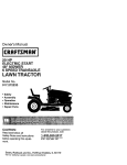
Owner's Manual
ICRnFTSMnN !
LAWN TRACTOR
21.0 HP, 48" Mower
Electric Start
Automatic Transmission
Model No.
917.273280
[1_
from
previously
start
the engine,
read
This product
has built
a lowengines.
emission Before
engine you
which
operates
differently
and understand this Owner's Manual.
IMPORTANT:
Read and follow all
Safety Rules and Instructions
before operating this equipment.
For answers to your questions
about this product, Call:
1-800-659-5917
Sears Craftsman Help Line
5 am - 5 pm, Mort - Sat
Sears, Roebuck and Co., Hoffman Estates,
Visit our Craftsman website: www.sears.com/craftsman
IL 60179
U.S.A.
Warranty ................................................
2
Safety Rules ..........................................
3
Product Specifications .......................... 5
Assembly/P re-Operation ....................... 7
Operation ...............................................
9
Maintenance Schedule ........................ 15
Maintenance ........................................
15
Service and Adjustments ..................... 19
Storage ................................................
27
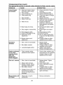
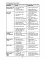
Troubleshooting ................................... 28
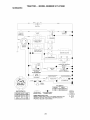
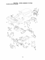
Repair Parts .........................................
32
Sears Service ........................ Back Cover
LIMITED WARRANTY ON CRAFTSMAN RIDING EQUIPMENT
For two (2) years from the date of purchase, if this Craftsman Riding Equipment is
maintained, lubricated and tuned up according to the instructions in the owner's manual,
Sears will repair or replace free of charge any parts that are found to be defective in
material or workmanship according to the guidelines of coverage listed below. Sears will
also provide free labor for these applicable warranted parts for the two full years. During
the first 30 days of purchase, there will be no charges to service the product at your
home for issues covered by this warranty. (See exclusions below). For your convenience, IN HOME warranty service will still be available after the first 30 days of purchase, but a trip charge will apply. This charge will be waived if the Craftsman product is
dropped off at an authorized Sears location. For the nearest authorized Sears location,
please call 1-800-4-MY-HOME®.
This warranty applies only while this product is within
the United States.
This Warranty does not cover:
• Expendable items which become worn during normal use, including but not limited to
blades, spark plugs, air cleaners, belts, and oil filters.
• Standard Maintenance Servicing, oil changes, or tune-ups
• Tire replacement or repair caused by punctures from outside objects, such as nails,
thorns, stumps, or glass.
• Repairs necessary because of operator abuse, including but not limited to, damage
caused by towing objects beyond the capability of the riding equipment, impacting
objects that bend the frame or crankshaft, or over-speeding the engine.
• Repairs necessary because of operator negligence, including but not limited to, electrical and mechanical damage caused by improper storage, failure to use the proper
grade and amount of engine oil, failure to keep the deck clear of flammable debris,
or failure to maintain the equipment according to the instructions contained in the
owner's manual.
• Engine (fuel system) cleaning or repairs caused by fuel determined to be contaminated or oxidized (stale). In general, fuel should be used within 30 days of its purchase date.
• Normal deterioration and wear of the exterior finishes, or product label replacement.
• Riding equipment used for commercial or rental purposes.
LIMITED WARRANTY ON BATTERY
For ninety (90) days from date of purchase, if any battery included with this riding equipment proves defective in material or workmanship and our testing determines the battery
will not hold a charge, Sears will replace the battery at no charge. During the first 30
days of purchase, there will be no charges to replace the battery at your HOME. After
the first 30 days, for your convenience, IN-HOME warranty service will still be available but a trip charge will apply. This charge will be waived if the Craftsman product is
dropped off at an authorized Sears location. For the nearest authorized Sears location,
please call 1-800-4-MY-HOME®.
This battery warranty applies only while this product is within the United States.
This warranty gives you specific legal rights, and you may also have other rights, which
vary, from state to state.
Sears, Roebuck and Co.,Dept.817WA, Hoffman Estates, IL 60179
2
IMPORTANT: This cutting machine is capable of amputating hands and feet and throwing objects. Failure to observe the following safety instructions could result in serious
injury or death.
• Be aware of the mower discharge direction and do not point it at anyone. Do
not operate the mower without either
the entire grass catcher or the guard in
place.
• Slow down before turning.
• Never leave a running machine unattended. Always turn off blades, set
parking brake, stop engine, and remove
keys before dismounting.
• Turn off blades when not mowing.
• Stop engine before removing grass
catcher or unclogging chute.
• Mow only in daylight or good artificial
light.
• Do not operate the machine while under
the influence of alcohol or drugs.
• Watch for traffic when operating near or
crossing roadways.
• Use extra care when loading or unloading the machine into a trailer or
truck.
• Data indicates that operators, age 60
years and above, are involved in a large
percentage of riding mower-related injuries. These operators should evaluate
their ability to operate the riding mower
safely enough to protect themselves and
others from serious injury.
• Keep machine free of grass, leaves or
other debris build-up which can touch
hot exhaust / engine parts and burn. Do
not allow the mower deck to plow leaves
or other debris which can cause buildup to occur. Clean any oil or fuel
spillage before operating or storing the
machine. Allow machine to cool before
storage.
_WARNING:
In order to prevent
accidental starting when setting up,
transporting, adjusting or making repairs,
always disconnect spark plug wire and
place wire where it cannot contact spark
plug.
_,WARNING:
Do not coast down a hill
in neutral, you may lose control of the
tractor.
_Ib WARNING: Tow only the attachments that are recommended by and
comply with specifications of the manufacturer of your tractor. Use common
sense when towing. Operate only at the
lowest possible speed when on a slope.
Too heavy of a load, while on a slope, is
dangerous. Tires can lose traction with
the ground and cause you to lose control
of your tractor.
WARNING: Engine exhaust, some
of its constituents, and certain vehicle
components contain or emit chemicals
known to the State of California to cause
cancer and birth defects or other reproductive harm.
_WARNING:
Battery posts, terminals
and related accessories contain lead and
lead compounds, chemicals known to the
State of California to cause cancer and
birth defects or other reproductive harm.
Wash hands after handling.
I. GENERAL
OPERATION
• Read, understand, and follow all instructions in the manual and on the machine
before starting.
• Only allow responsible adults, who are
familiar with the instructions, to operate
the machine.
• Clear the area of objects such as rocks,
toys, wire, etc., which could be picked
up and thrown by the blade.
• Be sure the area is clear of other people
before mowing. Stop machine if anyone
enters the area.
• Never carry passengers.
• Do not mow in reverse unless absolutely necessary. Always look down and
behind before and while backing.
II. SLOPE
OPERATION
Slopes are a major factor related to lossof-control and tipover accidents, which can
result in severe injury or death. All slopes
require extra caution. If you cannot back
up the slope or if you feel uneasy on it, do
not mow it.
3
DO:
• Mow up and down slopes, not across.
• Remove obstacles such as rocks, tree
limbs, etc.
• Watch for holes, ruts, or bumps. Uneven terrain could overturn the machine.
Tall grass can hide obstacles.
• Use slow speed. Choose a low gear
so that you will not have to stop or shift
while on the slope.
• Follow the manufacturer's recommendations for wheel weights or counterweights to improve stability.
• Use extra care with grass catchers or
other attachments. These can change
the stability of the machine.
• Keep all movement on the slopes slow
and gradual Do not make sudden
changes in speed or direction.
• Avoid starting or stopping on a slope. If
tires lose traction, disengage the blades
and proceed slowly straight down the
slope.
DO NOT:
• Never carry children. They may fall off
and be seriously injured or interfere with
safe machine operation.
• Never allow children to operate the
machine.
• Use extra care when approaching blind
corners, shrubs, trees, or other objects
that may obscure vision.
IV. SERVICE
• Use extra care in handling gasoline and
other fuels. They are flammable and
vapors are explosive.
- Use only an approved container.
- Never remove gas cap or add fuel
with the engine running. Allow
engine to cool before refueling. Do
not smoke.
- Never refuel the machine indoors.
- Never store the machine or fuel
container inside where there is an
open flame, such as a water heater.
• Never run a machine inside a closed
area.
• Keep nuts and bolts, especially blade
attachment bolts, tight and keep equipment in good condition.
• Never tamper with safety devices.
Check their proper operation regularly.
• Keep machine free of grass, leaves, or
other debris build-up. Clean oil or fuel
spillage. Allow machine to coot before
storing.
• Stop and inspect the equipment if you
strike an object. Repair, if necessary,
before restarting.
• Never make adjustments or repairs with
the engine running.
• Grass catcher components are subject
to wear, damage, and deterioration,
which could expose moving parts or
allow objects to be thrown. Frequently
check components and replace with
manufacturer's recommended parts,
when necessary.
• Mower blades are sharp and can cut.
Wrap the blade(s) or wear gloves, and
use extra caution when servicing them.
• Check brake operation frequently. Adiust and service as required.
• Do not turn on slopes unless necessary, and then, turn slowly and gradually
downhill, if possible.
• Do not mow near drop-offs, ditches,
or embankments. The mower could
suddenly turn over if a wheel is over
the edge of a cliff or ditch, or if an edge
caves in.
• Do not mow on wet grass. Reduced
traction could cause sliding.
• Do not try to stabilize the machine by
putting your foot on the ground.
• Do not use grass catcher on steep
slopes.
III. CHILDREN
Tragic accidents can occur if the operator
is not alert to the presence of children.
Children are often attracted to the machine and the mowing activity. Neverassume that children will remain where you
last saw them.
• Keep children out of the mowing area
and under the watchful care of another
responsible adult.
• Be alert and turn machine off if children
enter the area.
• Before and when backing, took behind
and down for small children.
4
• Remove obstacles such as rocks, tree
limbs, etc.
• Watch for holes, ruts, or bumps. Uneven
terrain could overturn the machine. Tall
grass can hide obstacles.
• Use slow speed. Choose a tow gear
so that you wilt not have to stop or shift
while on the slope.
• Avoid starting or stopping on a slope. If
tires lose traction, disengage the blades
and proceed slowly straight down the
slope.
• If machine stops while going uphill,
disengage blades, shift into reverse and
back down slowly.
• Do not turn on slopes unless necessary,
and then, turn slowly and gradually
downhill, if possible.
• Be sure the area is clear of other people
before mowing. Stop machine if anyone
enters the area.
• Never carry passengers or children
even with the blades off.
• Do not mow in reverse unless absolutely necessary. Always look down and
behind before and while backing.
• Never carry children. They may fall off
and be seriously injured or interfere with
safe machine operation.
• Keep children out of the mowing area
and under the watchful care of another
responsible adult.
• Be alert and turn machine off if children
enter the area.
• Before and when backing, took behind
and down for small children.
• Mow up and down slopes (15 ° Max), not
across.
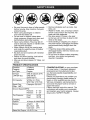
PRODUCT
SPECIFICATIONS
Gasoline
Capacity
and Type:
4 Gallons
Unleaded
Regular
Oil Type
API-SF-SJ):
SAE 30 (above 32°F)
SAE 5W-30
(below 32°F)
Oil Capacity:
W/Fitter 4.0 Pints
W!O Filter 3.75 Pints
Spark Plug:
(Gap: .040")
Champion
Ground Speed (MPH):
Forward:
Reverse:
Tire Pressure:
Charging
System:
Battery:
Front:
Rear:
CONGRATULATIONS
on your purchase
of a new tractor. It has been designed,
engineered and manufactured to give
you the best possible dependability and
performance.
Should you experience any problem you
cannot easily remedy, please contact a
Sears or other qualified service center.
We have competent, welt-trained technicians and the proper tools to service or
repair this tractor.
Please read and retain this manual. The
instructions will enable you to assemble
and maintain your tractor properly. Always
observe the "SAFETY RULES".
QC12YC
0 - 5.5
0 - 2.4
14 PSI
10 PSI
16 Amps @ 3600 RPM
Amp/Hr:
Min. CCA:
Case size:
35
280
UIR
Blade Bolt Torque: 45-55 Ft. Lbs.
5
CUSTOMER
RESPONSIBILITIES
Here's what's included in the Agreement:
• Expert service by our 12,000 profesional repair specialists.
• Unlimited service and no charge for
parts and labor on all covered repairs.
• Product replacement
if your covered
product can't be fixed.
• Discount of 10% from regular price of
service and service-related parts not
covered by the agreement; also, 10%
off regular price of preventive maintenance check.
• Fast help by phone- phone support
from a Sears technician on products
requiring in-home repair, plus convenient repair scheduling.
Once you purchase the Agreement, a
simple phone call is all that it takes for you
to schedule service. You can call anytime
day or night, or schedule a service appointment online.
Sears has over 12,000 professional repair
specialists, who have access to over 4.5
million quality parts and accessories.
That's the kind of professionalism you can
count on to help prolong the life of your
new purchase for years to come. Purchase
your Repair Protection Agreement today!
Some limitations and exclusions apply.
For prices and additional information
call 1-800-827-6655.
• Read and observe the safety rules.
• Follow a regular schedule in maintaining, caring for and using your tractor.
• Follow the instructions under "Maintenance" and "Storage" sections of this
owner's manual.
_il,WARNING: This tractor is equipped
with an internal combustion engine and
should not be used on or near any unimproved forest-covered, brush-covered or
grass-covered land unless the engine's
exhaust system is equipped with a spark
arrester meeting applicable local or state
taws (if any). If a spark arrester is used, it
should be maintained in effective working
order by the operator.
In the state of California the above is
required by law (Section 4442 of the
California Public Resources Code). Other
states may have similar taws. Federal
taws apply on federal lands. A spark arrester for the muffler is available through
your nearest Sears service center (See
REPAIR PARTS section of this manual).
REPAIR PROTECTION
AGREEMENTS
Congratulations on making a smart purchase. Your new Craftsman® product is
designed and manufactured for years of
dependable operation. But like all products, it may require repair from time to
time. That's when having a Repair Protection Agreement can save you money and
aggravation.
Purchase a Repair Protection Agreement
now and protect yourself from unexpected
hassle and expense.
SEARS INSTALLATION
SERVICE
For Sears professional installation of home
appliances, garage door openers, water
heaters, and other major home items, in
the U.S.A. call 1-800-4-MY-HOME®
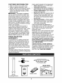
Keys
_I
(2) Keys
Video
For Future Use
Cassette
Slope Sheet
0
Mower
Leveling Wrench
Bubble Level
6
Your new tractor
you begin.
has been assembled
at the factory.
When right or left hand is mentioned in
this manual, it means, from your point of
view, when you are in the operating position (seated behind the steering wheel).
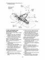
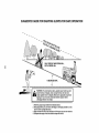
TO REMOVE TRACTOR
CARTON
Review
the video
cassette
before
Adiostment
FROM
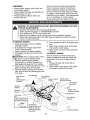
UNPACK CARTON
Knob
1. Cut along dotted lines on all four panels of carton. Remove end panels and
lay side panels flat.
2. Remove packing materials.
3. Remove protective materials from tractor hood and grille.
IMPORTANT: Check for and remove any
staplesin skid that may puncture tires
where tractor is to roll off skid.
NOTE: You may now roll or drive your
tractor off the skid. Follow the appropriate
instruction below to remove the tractor
from the skid.
TO ROLLTRACTOR
OFF SKID (See
Operation
section for location and
function of controls)
1. Press lift lever plunger and raise
attachment lift lever to its highest position.
2. Release parking brake by depressing
brake pedal.
3. Place freewheel control in "transmission disengaged" position (See "TO
TRANSPORT" in the Operation section
of this manual).
4. Roll tractor forward off skid.
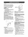
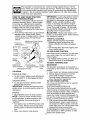
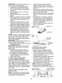
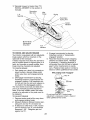
HOW TO SET UP YOUR TRACTOR
CHECK BATTERY
1. Lift hood to raised position.
NOTE: If this battery is put into service
after month and year indicated on label
(label located between terminals) charge
battery for minimum of one hour at 6-10
amps. (See "BATTERY" in Maintenance
section of this manual for charging instructions).
,,
ADJUST
.......
j
Label
SEAT
1.
Raise seat and loosen
knob.
adjustment
2.
Lower seat into operating
sit in seat.
position
and
3.
Slide seat until a comfortable
position
is reached which allows you to press
clutch/brake
pedal all the way down.
4. Get off seat without moving its adjusted position.
5. Raise seat and tighten adjustment
knob securely.
7
TO DRIVE TRACTOR
OFF SKID (See
Operation
section for location and
function of controls)
_WARNING:
Before starting, read, understand and follow all instructions in the
Operation section of this manual. Be sure
tractor is in a welt-ventilated area. Be sure
the area in front of tractor is clear of other
people and objects.
1. Be sure all the above assembly steps
have been completed.
2. Check engine oil level and fill fuel tank
with gasoline.
3. Place freewheel control in "transmission engaged" position. (See "TO
TRANSPORT" in the Operation section
of this manual).
4. Sit on seat in operating position, depress brake pedal and set the parking
brake.
5. Press lift lever plunger and raise
attachment lift lever to its highest position.
6. Start the engine.After engine has
started,move throttle controlto idle
position.
7. Releaseparkingbrake.
8. Slowlydepress forwarddrive pedal and
drivetractor off skid.
9. Applybraketo stop tractorand set
parkingbrake.
10.Turnignition key to "STOP"position.
Continuewith the instructionsthat follow.
JCHECKLIST
Before you operate your new tractor, we
wish to assure that you receive the best
performance and satisfaction from this
Quality Product.
Please review the following checklist:
,/ All assembly instructions have been
completed.
•/ No remaining loose parts in carton.
,/Battery is properly prepared and
charged.
(Minimum 1 hour at 6 amps).
,/Seat is adjusted comfortably and tightened securely.
,/All tires are properly inflated. (For shipping purposes, the tires were overinflated at the factory).
,/Be sure mower deck is properly leveled
side-to-side/front-to-rear
for best cutting
results. (Tires must be properly inflated
for leveling).
,/Check mower and drive belts. Be sure
they are routed properly around pulleys
and inside all belt keepers.
,/Check wiring. See that all connections
are still secure and wires are properly
clamped.
,/Before driving tractor, be sure freewheel
control is in "transmission engaged" position (see "To Transport" in the Operation section of this manual).
While learning how to use your tractor, pay
extra attention to the following important
items:
•/ Engine oil is at proper level.
,/Fuel tank is filled with fresh, clean, regular unleaded gasoline.
,/Become familiar with all controls, their
location and function. Operate them
before you start the engine.
,/Be sure brake system is in safe operating condition.
,/It is important to purge the transmission
before operating your tractor for the first
time. Follow proper starting and transmission purging instructions (See "TO
START ENGINE" and "PURGE TRANSMISSION" in the Operation section of
this manual).
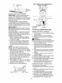
CHECKTIRE
PRESSURE
The tires on your tractor were overinflated
at the factory for shipping purposes. Correct tire pressure is important for best
cutting performance.
• Reduce tire pressure to PSI shown in
"PRODUCT SPECIFICATIONS" section
of this manual.
CHECK
DECK
LEVELNESS
For best cutting results, mower housing should be properly leveled. See "TO
LEVEL MOWER HOUSING" in the Service
and Adjustments section of this manual.
CHECK FOR PROPER POSITION
OF ALL BELTS
See the figures that are shown for replacing motion and mower blade drive belts
in the Service and Adjustments section
of this manual. Verify that the belts are
routed correctly.
CHECK BRAKESYSTEM
After you learn how to operate your tractor, check to see that the brake is properly
adjusted. See "TO ADJUST BRAKE" in
the Service and Adjustments section of
this manual.
8
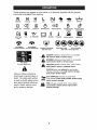
These symbols may appear on your tractor or in literature supplied with the product.
Learn and understand their meaning.
R
N
REVERSE
H
NEUTRAL
ENGINE OFF
HIGH
LIGHTS ON
OVER TEMP
LIGHT
FUEL
ENGINE ON
OIL PRESSURE
I'.,I
L
LOW
CHOKE
ENGINE START
BATTERY
FAST
PARKING
REVERSE
DRAKE
SLOW
IGNITION
PARKING DRAKE
LOCKED
FORWARD
MOWER
HEIGHT
PARKING BRAKE
UNLOCKED
MOWER
LIFT
@@@@@
ATTACHMENT
CLUTCH ENGAGED
ATTACHMENT
CLUTCH DISENGAGED
FREE WHEEL
(Automatic
Models only)
&
Failure to follow instructions
could result in serious injury or
death. The safety alert symbol
is used to identify safety information about hazards which can
result in death, serious injury
and/or property damage.
DANGER, KEEP HANDS
AND FEET AWAY
&
&
&
KEEP AREA CLEAR
(SEE SAFETY
SLOPE HAZARDS
RULES SECTION)
DANGER indicates a hazard which, if not avoided,
will result in death or serious injury.
WARNING indicates a hazard which, if not avoided,
could result in death or serious injury.
CAUTION indicates a hazard which, if not avoided,
might result in minor or moderate injury.
CAUTION when used without the alert symbol,
indicates a situation that could result in damage
to the tractor and/or engine.
HOT SURFACES indicates
.,,_ol.o. if not avoided, could result
and/or property damage.
a hazard which,
in death, serious injury
FIRE indicates a hazard which, if not avoided,
could result in death, serious injury and/or
property damage.
9
KNOW
READ
YOUR
YOUR
TRACTOR
THIS OWNER'S
TRACTOR
MANUAL
AND
SAFETY
RULES
BEFORE
OPERATING
Compare the illustrations
with your tractor to familiarize yourself with the locations
various controls and adjustments.
Save this manual for future reference.
Hourmeter
Ammeter
Ignition
Switch
Li
of
Switch Position
Attachment Clutch Switch
Drive Pedal
Lift Lever Plunger
Attachment Lift Lever
Throttle Control
Reverse Drive Pedal
Brake
o Height
Adjustment
Choke Control
g Brake
F_ewheel
-"-Cruise
Control Lever
I
Our tractors conform to the safety standards of the
American National Standards Institute.
ATTACHMENT CLUTCH SWITCH - Used
to engage the mower blades, or other attachments mounted to your tractor.
LIGHT SWITCH POSITION - Turns the
headlights on and off.
THROTTLE CONTROL - Used to control
engine speed.
CHOKE CONTROL - Used when starting
a cold engine.
BRAKE PEDAL - Used for braking the
tractor and starting the engine.
FREEWHEEL CONTROL - Disengages
transmission for pushing or slowly towing
the tractor with the engine off.
ATTACHMENT LIFT LEVER - Used to
raise, lower and adjust the mower deck or
other attachments mounted to your tractor.
LIFT LEVER PLUNGER - Used to release
attachment lift lever when changing its
position.
IGNITION SWITCH - Used for starting and
stopping the engine.
AMMETER - Indicates battery charging
(+) or discharging (-).
PARKING BRAKE - Locks clutch/brake
into the brake position.
FORWARD DRIVE PEDAL - Used for
forward movement of tractor.
REVERSE DRIVE PEDAL - Used for
reverse movement of tractor.
CRUISE CONTROL LEVER - Used to set
forward movement of tractor at desired
speed without holding the forward drive
pedal.
HOURMETER - Indicates hours of operation.
10
The operation of any tractor can result in foreign objects thrown into the
eyes, which can result in severe eye damage. Always wear safety glasses
or eye shields while operating your tractor or performing any adjustments
or repairs. We recommend standard safety glasses or a wide vision safety
mask worn over spectacles.
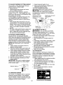
HOW TO USE YOUR TRACTOR
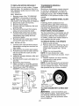
TO SET PARKING
BRAKE
Your tractor is equipped with an operator
presence sensing
switch. When engine
is running, any attempt by the operator
to leave the seat without first setting the
parking brake wilt shut off the engine.
1. Depress brake pedal all the way down
and hold.
2. Pull parking brake lever up and release
pressure from brake pedal. Pedal
should remain in brake position.
Make
sure parking brake wilt hold tractor
secure.
Attachment Clutch Switch
Push-In to
Pull Out To "Engage"
Ignition <ey
Choke
Control
Throttle
Control_
"Brake"Position
Drive
k_
o
Bra
t
"Drive" Position
"Disengaged"
Pedal
Brake
"Engaged" Position Control
Position
Lever
STOPPING
MOWER
BLADES
-
• To stop mower blades, push attachment
clutch switch in to disengaged
position.
GROUND
DRIVE-
• To stop ground drive, depress brake
pedal all the way down.
IMPORTANT:
Forward and reverse drive
pedals return to neutral position when not
depressed.
ENGINE • Move throttle control to stow position.
NOTE: Failure to move throttle control
to slow position to allow engine to idle
before stopping may cause engine to
"backfire".
• Turn ignition key to "STOP" position and
remove key. Always remove key when
leaving tractor to prevent unauthorized
use.
• Never use choke to stop engine.
11
IMPORTANT: Leaving the ignition switch in
any position other than "STOP" will cause
the battery to discharge and go dead.
NOTE: Under certain conditions when
tractor is standing idle with the engine
running, hot engine exhaust gases may
cause "browning" of grass. To eliminate
this possibility, always stop engine when
stopping tractor on grass areas.
CAUTION.- Always stop tractor completely, as described above, before leaving
the operator's position.
THROTTLE CONTROL
Always operate engine at full throttle.
• Operating engine at less than full
throttle reduces the battery charging
rate.
• Full throttle offers the best bagging and
mower performance.
TO USE CHOKE CONTROL
Use choke control whenever you are starting a cold engine. Do not use to start a
warm engine.
• To engage choke control, putt knob out.
Slowly push knob in to disengage.
TO MOVE FORWARD AND
BACKWARD
The direction and speed of movement is
controlled by the forward and reverse drive
pedals.
1. Start tractor and release parking brake.
2. Slowly depress forward or reverse
drive pedal to begin movement.
Ground speed increases the further
down the pedal is depressed.
TO USE CRUISE CONTROL
The cruise control feature can be used for
forward travel only.
SYSTEM CHARACTERISTICS
The cruise control should only be used
while mowing or transporting on relatively
smooth, straight surfaces. Other conditions
such as trimming at stow speeds may
cause the cruise control to disengage. Do
not use the cruise control on slopes, rough
terrian or while trimmimg or turning.
1. With forward drive pedal depressed to
desired speed, move cruise control lever forward to "SET" position and hold
while lifting your foot off the pedal, then
release the cruise control lever.
To disengage the cruise control, pull the
lever backward to "OFF" position, or fully
depress the brake pedal.
TO ADJUST MOWER CUTTING HEIGHT
The position of the attachment lift lever
determines the cutting height.
• Grasp lift lever.
• Press plunger with thumb and move
lever to desired position.
The cutting height range is approximately 1-1/2 to 4". The heights are measured from the ground to the blade tip with
the engine not running.
These heights are approximate and may
vary depending upon soil conditions,
height of grass and types of grass being
mowed.
• The average lawn should be cut to approximately 2-1/2 inches during the cool
season and to over 3 inches during hot
months. For healthier and better looking
lawns, mow often and after moderate
growth.
• For best cutting performance, grass over
6 inches in height should be mowed
twice. Make the first cut relatively high;
the second to desired height.
TO ADJUST GAUGE WHEELS
Gauge wheels are properly adjusted
when they are slightly off the ground when
mower is at the desired cutting height in
operating position. Gauge wheels then
keep the deck in proper position to help
prevent scalping in most terrain conditions.
NOTE: Be sure tractor is on a flat level
surface.
1. Lower mower and adjust mower to
desired cutting height.
2. Remove retainer spring and clevis pin
which secure each gauge wheel bar.
3. Lower gauge wheels to ground. Raise
gauge wheels slightly to align holes
in bracket and gauge wheel bar and
insert clevis pin. Gauge wheels should
be slightly off the ground.
4. Replace retainer spring into clevis pin.
5. Be sure all gauge wheels are in the
same setting.
IMPORTANT: Be sure to readjust gauge
wheels if you change the cutting height
of the mower deck.
1.
2.
Select desired height of cut.
Start mower blades by engaging attachment clutch control.
TO STOP MOWER BLADES _cengage
attachment
clutch control.
AUTION:
Do not operate the mower
without either the entire grass catcher,
on mowers so equipped, or the deflector
shield in place.
Attachment Lift Lever
Attachment Clutch
High Position
Switch Pull Out To
iZ:--_ Low
Position
Deflector
Shield
Push tn To
"Disengage" _
TO OPERATE ON HILLS
AI_WARNING: Do not drive up or down
hills with slopes greater than 15 ° and do
not drive across any slope. Use the slope
guide at the back of this manual.
• Choose the slowest speed before starting up or down hills.
• Avoid stopping or changing speed on
hills.
• If stopping is absolutely necessary, push
brake pedal quickly to brake position
and engage parking brake.
• To restart movement, slowly release
parking brake and brake pedal.
• Slowly depress appropriate drive pedal
to slowest setting.
• Make all turns slowly.
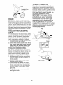
TO TRANSPORT
When pushing or towing your tractor, be
sure to disengage transmission by placing
freewheel control in freewheeling position.
Freewheel control is located at the rear
drawbar of tractor.
1. Raise attachment lift to highest position
with attachment lift control.
2. Pull freewheel control out and down
into the slot and release so it is held in
the disengaged position.
• Do not push or tow tractor at more than
two (2) MPH.
• To re-engage transmission, reverse
above procedure.
Transmission
Engaged
Retainer Spring
Clevis
TO OPERATE MOWER
Your tractor is equipped with an operator
presence sensing switch. Any attempt
by the operator to leave the seat with the
engine running and the attachment clutch
engaged will shut off the engine.
12
Transmission
Disengaged
NOTE: To protect hood from damage
when transporting your tractor on a truck
or a trailer, be sure hood is closed and
secured to tractor. Use an appropriate
means of tying hood to tractor (rope, cord,
etc.).
TOWING CARTS AND OTHER ATTACHMENTS
Tow only the attachments that are recommended by and comply with specifications
of the manufacturer of your tractor. Use
common sense when towing. Too heavy of
a load, while on a slope, is dangerous. Tires
can lose traction with the ground and cause
you to lose control of your tractor.
BEFORE
CHECK
STARTING
ENGINE
THE
ENGINE
OIL LEVEL
The engine in your tractor has been
shipped, from the factory, already filled
with summer weight oil.
1. Check engine oil with tractor on level
ground.
2. Remove oil fill cap/dipstick and wipe
clean, reinsert the dipstick and screw
cap tight, wait for a few seconds, remove and read oil level. If necessary,
add oil until "FULl" mark on dipstick is
reached. Do not overfill.
• For cold weather operation you should
change oil for easier starting (See the
oil viscosity chart in the Maintenance
section of this manual).
• To change engine oil, see the Maintenance section in this manual.
ADD GASOLINE
• Fill fuel tank to bottom of tank filler neck.
Do not overfill. Use fresh, clean, regular
unleaded gasoline with a minimum of
87 octane. (Use of leaded gasoline wilt
increase carbon and lead oxide deposits
and reduce valve life). Do not mix oil
with gasoline. Purchase fuel in quantities that can be used within 30 days to
assure fuel freshness.
_i, CAUTION: Wipe off any spilled oil or
fuel. Do not store, spill or use gasoline
near an open flame.
IMPORTANT: When operating in temperatures below 32°F(0°C), use fresh, clean
winter grade gasoline to help insure good
cold weather starting.
CAUTION: Alcohol blended fuels (called
gasohol or using ethanol or methanol) can
attract moisture which leads to separation and formation of acids during storage.
Acidic gas can damage the fuel system of
an engine while in storage.
13
To avoid engine problems, the fuel system
should be emptied before storage of 30
days or longer. Drain the gas tank, start the
engine and let it run until the fuel lines and
carburetor are empty. Use fresh fuel next
season. See Storage Instructions for additional information.
Never use engine or carburetor cleaner
products in the fuel tank or permanent damage may occur.
TO START ENGINE
When starting the engine for the first time
or if the engine has run out of fuel, it will
take extra cranking time to move fuel from
the tank to the engine.
1. Be sure freewheel control is in the
transmission engaged position.
2. Sit on seat in operating position,
depress brake pedal and set parking
brake.
3. Move attachment clutch to disengaged
position.
4. Move throttle control to fast position
5. Pull choke control out for a cold engine
start attempt. For a warm engine start
attempt the choke control may not be
needed.
NOTE: Before starting, read the warm and
cold starting procedures below.
6. Insert key into ignition and turn key
clockwise to start position and release
key as soon as engine starts. Do
not run starter continuously for more
than fifteen seconds per minute. If the
engine does not start after several
attempts, push choke control in, wait
a few minutes and try again. If engine
still does not start, pull the choke control out and retry.
WARM WEATHER STARTING (50 ° F and
above)
7. When engine starts, slowly push choke
control in until the engine begins to
run smoothly. If the engine starts to
run roughly, putt the choke control out
slightly for a few seconds and then
continue to push the control in slowly.
• The attachments and ground drive can
now be used. If the engine does not
accept the toad, restart the engine and
allow it to warm up for one minute using
the choke as described above.
COLD WEATHER STARTING (50 ° F and
below)
7. When engine starts, slowly push choke
control in until the engine begins to run
smoothly. Continue to push the choke
control in small steps allowing the engine to accept small changes in speed
and load, until the choke control is fully
in.
•
If the engine starts to run roughly, pull
the choke control out slightly for a few
seconds and then continue to push the
control in slowly. This may require an
engine warm-up period from several
seconds to several minutes, depending
on the temperature.
AUTOMATIC TRANSMISSION WARM UP
Before driving the unit in cold weather,
the transmission should be warmed up as
follows:
1. Be sure the tractor is on level ground.
2. Release the parking brake and let the
brake slowly return to operating position.
3. Allow one minute for transmission to
warm up. This can be done during the
engine warm up period.
• The attachments can be used during
the engine warm-up period after the
transmission has been warmed up and
may require the choke control be pulled
out slightly.
NOTE: If at a high altitude (above 3000
feet) or in cold temperatures (below 32 F)
the carburetor fuel mixture may need to
be adjusted for best engine performance.
(See "TO ADJUST CARBURETOR" in the
Service and Adjustments section of this
manual).
PURGE TRANSMISSION
_CAUTION:
Never engage or disengage
freewheel lever while the engine is running.
To ensure proper operation and performance, it is recommended that the transmission be purged before operating tractor
for the first time. This procedure wilt remove
any trapped air inside the transmission
which may have developed during shipping
of your tractor.
IMPORTANT: Should your transmission
require removal for service or replacement, it should be purged after reinstallation before operating the tractor.
1. Place tractor safely on level surface
with engine off and parking brake set.
2. Disengage transmission by placing
freewheel control in disengaged position (See "TO TRANSPORT" in this
section of manual).
3. Sitting in the tractor seat, start engine.
After the engine is running, move
throttle control to slow position. Disengage parking brake.
4. Depress forward drive pedal to full forward
position and hold for five (5) seconds
and release pedal. Depress reverse drive
pedal to full reverse position and hold
for five (5) seconds and release pedal.
Repeat this procedure three (3) times.
NOTE: During this step there will be no
movement of drive wheels. The air is being
removed from hydraulic drive system.
5. Shut off engine and set parking brake.
6. Engage transmission by placing
freewheel control in "transmission
engaged" position (See "TO TRANSPORT" in this section of manual).
7. Sitting in the tractor seat, start engine.
After the engine is running, move
throttle control to half (1/2) speed.
Disengage parking brake.
8. Drive tractor forward for approximately
five feet then backwards for five feet. Repeat this driving procedure three times.
Your transmission is now purged and
ready for normal operation.
MOWING TIPS
• Mower should be properly leveled for
best mowing performance. See "TO
LEVEL MOWER HOUSING" in the
Service and Adjustments section of this
manual.
• The left hand side of mower should be
used for trimming.
• Drive so that clippings are discharged
onto the area that has already been
cut. Have the cut area to the right of
the tractor. This wilt result in a more
even distribution of clippings and more
uniform cutting.
• When mowing large areas, start by
turning to the right so that clippings wilt
discharge away from shrubs, fences,
driveways, etc. After one or two rounds,
mow in the opposite direction making
left hand turns until finished.
J
• If grass is extremely tall, it should be
mowed twice to reduce load and possible fire hazard from dried clippings.
Make first cut relatively high; the second
to the desired height.
• Do not mow grass when it is wet.
Wet grass will plug mower and leave
undesirable clumps. Allow grass to dry
before mowing.
• Always operate engine at full throttle
when mowing to assure better mowing
performance and proper discharge of
material. Regulate ground speed by
selecting a low enough gear to give the
mower cutting performance as welt as
the quality of cut desired.
• When operating attachments, select a
ground speed that will suit the terrain
and give best performance of the attachment being used.
14
EILL,.OATES
AS YOU COMPLETE
REGULAR SERV,CE
S E R V IC E DATES
_'_.,//_'/_"
/n
BrakePressure
Operation
Check Tire
_V'
T
Check Operator Presence and
Interlock Systems
I1_
a
Check for Loose Fasteners
_
T
Lubrication
0
Check
Battery Level
Sharpen/Replace
Mower Blades
Clean Battery and Terminals
_s
Check Transaxle
ql_
R
m_'s
Chart
Cooling
Check V-Belts
Check Engine Oil Level
_
Change Engine Oil (with oil filter)
_1,2
E
Change
N
G
C,eanAirFi,ter
Clean Air Screen
N_
Inspect Muffler/Spark
E
Replace Oil Filter (if equipped)
_2
Clean Engine Cooling
_
Engine
Oil (without
oil filter)
_'1,2
_,:
Arrester
Fins
2
Replace Spark Plug
_
Replace Air Filter Paper Cartridge
V'2
Replace
Fuel
Filter
t _ Change more often when operating under a heavy load or
in high ambient temperatures.
2 - Service more often when operating in dirty or dusty conditions.
GENERAL
3 - Replace blades more often when mowing in sandy soil.
4 - Not required if equipped with maintenance-tree
battery.
5 - Tighten front axle pivot bolt to 35 ft.qbs, maximum.
Do not overtighten.
RECOMMENDATIONS
The warranty
on this tractor
LUBRICATION
does not
cover items that have been subjected to
operator abuse or negligence.
To receive
full value from the warranty, operator
07 Spindle
Zerk
must maintain tractor as instructed
in this
manual.
Some adjustments
will need to be made
periodically
to properly maintain your
tractor.
At least once a season, check to see if
you should make any of the adjustments
described
in the Service and Adjustments
section of this manual.
• At least once a year you should replace
the spark plug, clean or replace air filter,
and check blades and belts for wear.
A new spark plug and clean air filter
assure proper air-fuel mixture and help
your engine run better and last longer.
BEFORE
EACH
(1) Spindle
Zerk
(1) Front
Wheel
Bearing
Zerk
07 Front
Wheel
Bearing
Zerk
07
@ Engine
Zerks
i
d) General Purpose Grease
@ Refer to Maintenance "ENGINE" Section
IMPORTANT: Do not oil or grease the
pivot points which have special nylon
bear-ings. Viscous lubricants wilt attract
dust and dirt that wilt shorten the life of the
self-lubricating bearings. If you feel they
must be lubricated, use only a dry, powdered graphite type lubricant sparingly.
USE
Check engine oil level.
Check brake operation.
Check tire pressure.
Check operator presence and
interlock systems for proper operation.
5. Check for loose fasteners.
CHART
1.
2.
3.
4.
15
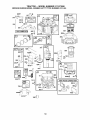
TRACTOR
IMPORTANT: To ensure proper assembly,
center hole in blade must align with star
on mandrel assembly.
4. Install and tighten blade bolt securely
(45-55 Ft. Lbs. torque).
IMPORTANT:
Special blade bolt is heat
treated.
Always observe safety rules when performing any maintenance.
BRAKE OPERATION
If tractor requires more than six (6) feet
stopping distance at high speed in highest
gear, then brake must be adjusted. (See
"TO ADJUST BRAKE" in the Service and
Adjustments section of this manual).
TIRES
• Maintain proper air pressure in all tires
(See "PRODUCT SPECIFICATIONS"
section of this manual).
• Keep tires free of gasoline, oil, or insect
control chemicals which can harm rubber.
• Avoid stumps, stones, deep ruts, sharp
objects and other hazards that may
cause tire damage.
NOTE: To seal tire punctures and prevent
flat tires due to stow leaks, tire sealant
may be purchased from your local parts
dealer. Tire sealant also prevents tire dry
rot and corrosion.
OPERATOR PRESENCE SYSTEM
(Special) "'--_.__
TO SHARPEN
_" Star
BLADE
NOTE: We do not recommend sharpening blade - but if you do, be sure the
blade is balanced.
Care should be taken to keep the blade
balanced. An unbalanced blade wilt cause
excessive vibration and eventual damage
to mower and engine.
• The blade can be sharpened with a file
or on a grinding wheel. Do not attempt
to sharpen while on the mower.
• To check blade balance, you will need a
5/8" diameter steel bolt, pin, or a cone
balancer. (When using a cone balancer,
follow the instructions supplied with
balancer.)
NOTE: Do not use a nail for balancing
blade. The lobes of the center hole may
appear to be centered, but are not.
• Slide blade on to an unthreaded portion
of the steel bolt or pin and hold the
bolt or pin parallel with the ground. If
blade is balanced, it should remain in a
horizontal position. If either end of the
blade moves downward, sharpen the
heavy end until the blade is balanced.
Be sure that operator presence and
interlock systems are working properly. If
your tractor does not function as described
below, repair the problem immediately.
• The engine should not start unless
the brake pedal is fully depressed
and
attachment
clutch control is in the disengaged position.
• When the engine is running, any attempt by the operator to leave the seat
without first setting the parking brake
should shut off the engine.
• When the engine is running and the
attachment
clutch is engaged, any attempt by the operator to leave the seat
should shut off the engine.
• The attachment
clutch should never operate unless the operator is in the seat.
BLADE CARE
Center Hole
For best results mower blades must be
kept sharp. Replace bent or damaged
blades.
BLADE
Mandrel
Assembly
Trailing
Blade
5/8" Bolt
or Pin
REMOVAL
1. Raise mower to highest position to atlow access to blades.
NOTE: Protect your hands with gloves
and/or wrap blade with heavy cloth.
2. Remove blade bolt by turning counterclockwise.
3. Install new or resharpened blade with
stamped "THIS SIDE UP" facing deck
and mandrel assembly.
BATTERY
16
Your tractor has a battery charging system
which is sufficient for normal use. However, periodic charging of the battery with
an automotive charger will extend its life.
• Keep battery and terminals clean.
• Keep battery bolts tight.
• Keep small vent holes open.
• Recharge at 6-10 amperes for I hour.
NOTE:The original equipmentbattery on
your tractor is maintenancefree. Do not
attemptto open or removecaps or covers.
Adding or checking levelof electrolyteis
not necessary.
TO CLEAN
BATTERY
SAE VtSCOS_TY
-20
.30
-20
TEMPERATURE
AND TERMINALS
Corrosion and dirt on the battery and
terminals can cause the battery to "leak"
power.
1. Remove terminal guard.
2. Disconnect BLACK battery cable first
then RED battery cable and remove
battery from tractor.
3. Rinse the battery with plain water and
dry.
4. Clean terminals and battery cable ends
with wire brush until bright.
5. Coat terminals with grease or petroleum jelly.
6. Reinstall battery (See "REPLACING
BATTERY" in the SERVICE AND ADJUSTMENTS section of this manual).
TRANSAXLE COOLING
The transmission fan and cooling fins
should be kept clean to assure proper
cooling.
Do not attempt to clean fan or transmission while engine is running or while the
transmission is hot. To prevent possible
damage to seals, do not use high pressure
water or steam to clean transaxte.
• Inspect cooling fan to be sure fan blades
are intact and clean.
• Inspect cooling fins for dirt, grass clippings and other materials. To prevent
damage to seals, do not use compressed air or high pressure sprayer to
clean cooling fins.
30
GRADES
32
.10
0
RANGE ANT]CIPATED
60
BEFORE
80
IO0
20
30
NEXT OIL CHANGE
40
NOTE: Although multi-viscosity oils
(5W30, 10W30 etc.) improve starting in
cold weather, they will result in increased
oil consumption when used above 32°E
Check your engine oil level more frequently to avoid possible engine damage from
running tow on oil.
Change the oil after every 50 hours of operation or at least once a year if the tractor
is not used for 50 hours in one year.
Check the crankcase oil level before starting the engine and after each eight (8)
hours of operation. Tighten oil fill cap/
dipstick securely each time you check the
oil level.
TO CHANGE
ENGINE
OIL
Determine temperature range expected
before oil change. All oil must meet API
service classification SF-SJ.
• Be sure tractor is on level surface.
• Oil will drain more freely when warm.
• Catch oil in a suitable container.
1. Remove oil fill cap/dipstick. Be careful
not to allow dirt to enter the engine
when changing oil.
2. Remove yellow cap from end of drain
valve and install the drain tube onto the
fitting.
Oil Drain Valve
Closed
and
TRANSAXLE
PUMP FLUID
The transaxle was sealed at the factory
and fluid maintenance is not required for
the life of the transaxle. Should the transaxle ever leak or require servicing, contact
a sears or other qualified service center.
Locked
Position
V-BELTS
Check V-belts for deterioration and wear
after 100 hours of operation and replace
if necessary. The belts are not adjustable.
Replace belts if they begin to slip from
wear.
Yellow
Drain Tube
Unlock drain valve by pushing inward
slightly and turning counterclockwise.
4. To open, pull out on the drain valve.
5. After oil has drained completely, close
and lock the drain valve by pushing
inward and turning clockwise until the
pin is in the locked position as shown.
Remove the drain tube and replace the
cap onto the end of the drain valve.
=
ENGINE
LUBRICATION
Only use high quality detergent oil rated
with API service classification SF-SJ. Select the oil's SAE viscosity grade according
to your expected operating temperature.
=
17
CLEAN AIR SCREEN
7. Refill enginewith oil through oil fill dipsticktube. Pour slowly. Do not overfill.
Forapproximatecapacitysee "PRODUCT SPECIFICATIONS"section of this
manual.
8. Use gauge on oil fill cap/dipstickfor
checkinglevel. Foraccuratereading,
tighten dipstickcap securely onto the
tube beforeremovingdipstick. Keepoil
at "FULl" line on dipstick.Tightencap
onto the tube securely when finished.
ENGINEOIL FILTER
Replacethe engine oil filter every season
or everyother oil change if the tractoris
used morethan 100 hours in one year.
Air screen must be kept free of dirt and
chaff to prevent engine damage from
overheating. Clean with a wire brush or
compressed air to remove dirt and stubborn dried gum fibers.
CLEAN
AREAS
To insure proper cooling, make sure the
grass screen, cooling fins, and other
external surfaces of the engine are kept
clean at all times.
Every 100 hours of operation (more often
under extremely dusty, dirty conditions),
remove the blower housing and other cooling shrouds. Clean the cooling fins and
external surfaces as necessary. Make sure
the cooling shrouds are reinstalled.
NOTE: Operating the engine with a
blocked grass screen, dirty or plugged
cooling fins, and/or cooling shrouds
removed wilt cause engine damage due to
overheating.
AIR FILTER
Your engine wilt not run properly using a
dirty air filter. Clean the foam pre-cteaner
after every 25 hours of operation or every
season. Service paper cartridge every
100 hours of operation or every season,
whichever occurs first.
Service air cleaner more often under dusty
conditions.
1. Remove knobs and cover.
TO SERVICE
AIR INTAKE/COOLING
MUFFLER
Inspect and replace corroded muffler and
spark arrester (if equipped) as it could create a fire hazard and/or damage.
PRE-CLEANER
SPARK PLUG(S)
Replace spark plug(s) at the beginning
of each mowing season or after every
100 hours of operation, whichever occurs
first. Spark plug type and gap setting are
shown in "PRODUCT SPECIFICATIONS"
section of this manual.
2. Wash it in liquid detergent and water.
3. Squeeze it dry in a clean cloth.
4. Saturate it in engine oil. Wrap it in
clean, absorbent cloth and squeeze to
remove excess oil.
NOTE: If very dirty or damaged, replace
pre-cteaner.
TO SERVICE CARTRIDGE
1. Clean cartridge by tapping gently on
flat surface. If very dirty or damaged,
replace cartridge.
2. Reinstall precteaner cartridge, cover
and secure with knobs.
IMPORTANT: Petroleum solvents, such
as kerosene, are not to be used to clean
the cartridge. They may cause deterioration of the cartridge. Do not oil cartridge.
Do not use pressurized air to clean or dry
cartridge.
IN-LINE FUEL FILTER
The fuel filter should be replaced once
each season. If fuel filter becomes
clogged, obstructing fuel flow to carburetor, replacement is required.
1. With engine coot, remove filter and
plug fuel line sections.
2. Place new fuel filter in position in fuel
line with arrow pointing towards carburetor.
3. Be sure there are no fuel line leaks and
clamps are properly positioned.
4. Immediately wipe up any spilled gasoline.
Cover
Foam
18
CLEANING
We do not recommend using a garden
hose or pressure washer to clean your
tractor unless the engine and transmission are covered to keep water out. Water
in engine or transmission will shorten the
useful life of your tractor. Use compressed
air or a leaf blower to remove grass,
leaves and trash from tractor and mower.
• Clean engine, battery, seat, finish, etc.
of all foreign matter.
• Keep finished surfaces and wheels free
of all gasoline, oil, etc.
• Protect painted surfaces with automotive type wax.
WARNING:TO
AVOID SERIOUS INJURY, BEFORE PERFORMING ANY SERVICE OR ADJUSTMENTS:
1. Depress brake pedal fully and set parking brake.
2. Place attachment clutch in "DISENGAGED" position.
3. Turn ignition key "STOP" and remove key.
4. Make sure the blades and all moving parts have completely stopped.
5. Disconnect spark plug wire from spark plug and place wire where it cannot
come in contact with plug.
TO REMOVE MOWER
1. Place attachment clutch in "DISENGAGED" position.
2. If equipped, turn height adjustment
knob to lowest setting.
3. Lower mower to its lowest position.
4. Disengage belt tension rod from lock
Al_ bracket.
CAUTION: Rod is spring loaded. Have
a tight grip on rod and release slowly.
5. Remove retainer spring holding
anti-swaybar to chassis bracket and
disengage anti-sway bar from bracket.
6. Remove four retainer springs from front
plate assembly and remove plate.
7. Remove retainer springs from suspension arms at deck and disengage arms
from deck.
Lock Bracket
Belt Tension
Rod
(Disengaged _-_"/77
,,
Position)
_
8. Raise attachment lift to its highest position.
9. Slide mower forward and remove belt
from electric clutch pulley.
10.Slide mower out from under right side
of tractor.
TO INSTALL MOWER
Be sure tractor is on level surface and
mower suspension arms are raised with
attachment lift control. Engage parking
brake.
1. Swing anti-sway bar to left side of
mower deck.
2. Slide mower under tractor with deflector shield to right side of tractor.
Front Mower
Bracket
Electric Clutch
Pulley
Double Loop
Retainer Springs
Front Plate
Assembly
Chassis
Bracket
f
Retainer
Spring
anged Pins
Anti-Swa'
Bar
Front Mower
Bracket
USE PLIERS FOR
RET_j
Single Loop
Retainer Springs
Loop u_S
Suspension
Arms Double Loop
Retainer Springs
(Outward pointing
deck pins)
\
Deflector Shield
19
IMPORTANT: Check belt for proper routing in all mower pulley grooves.
3. If equipped, turn height adjustment
knob counterclockwise until it stops.
4. Lower mower linkage with attachment
lift control.
5. Be sure belt tension rod is in disengaged position.
6. Install belt into electric clutch pulley
groove.
7. Place the suspension arms on outward
pointing deck pins. Retain with double
loop retainer spring with loops up as
shown.
8. Install front plate assembly to tractor
suspension brackets and retain with
single loop retainer springs as shown.
9. Position front plate assembly between
front mower brackets. Raise deck and
plate assembly to align holes and
insert flanged pins. Secure pins with
double loop retainer springs between
the plate assembly and mower brackets.
NOTE: To assist in locating hole in flanged
pin, the hole in pin is intine with notch on
head of pin. If necessary, move mower
side-to-side to give space between plate
and mower brackets.
IMPORTANT: Check belt for proper routing in all mower pulley grooves.
10. Engage belt tension rod by pushing rod
into locking bracket.
_i, CAUTION: Belt tension rod is spring
loaded. Have a tight grip on rod and engage slowly.
11. Connect anti-sway bar to chassis
bracket under left footrest and retain
with double loop retainer spring.
12. If equipped, turn height adjustment
knob clockwise to remove slack from
mower suspension.
13. Raise deck to highest position.
TO LEVEL MOWER HOUSING
Adjust the mower while tractor is parked
on level ground such as a carport or garage. Make sure tires are properly inflated
(See "PRODUCT SPECIFICATIONS"
section of this manual).
If tires are over or
underinflated, you will not properly adjust
your mower.
SIDE-TO-SIDE
ADJUSTMENT
BUBBLE LEVEL
• Using the lift lever, place mower in
position where no part of the mower,
including gauge wheels, is touching the
ground.
• From left side of tractor, find the level
decal on top of mower and place bubble
level on decal as indicated.
• Mower is level side-to-side when bubble
is between the two lines in the bubble
level.
• If adjustment is necessary, under left
hand footrest, turn lift link adjustment
nut (above yellow cap) in appropriate
direction to bring bubble between the
lines in the bubble level.
• Remove bubble level from mower and
store in a safe place.
Bubble Between
Lines
Bubble Level
Level Decal
Brake
Pedal
Left Hand
Footrest
ALTERNATE SIDE-TO-SIDE
ADJUSTMENT METHOD
• Raise mower to its highest position.
• Measure height from bottom edge of
mower to ground level at front corners
of mower. Distance "A" on both sides of
mower should be the same.
• If adjustment is necessary, make adjustment on one side of mower only.
• To raise one side of mower, tighten lift
link adjustment nut on that side.
• To lower one side of mower, loosen lift
link adjustment nut on that side.
NOTE:
Each full turn of adjustment nut
will change mower height about 3/16".
• Recheck measurements after adjusting.
Bottom Edge of
WITH
Mower to Ground
\
NOTE: If necessary, check side-to-side
surface below tractor for levelness with a
tong board and the bubble level.
20
Bottom Edge of
Mower to Ground
/
BOTH FRONT PLATE LINKS MUST BE
EQUAL IN LENGTH
Suspension
Arm
--
FRON_TO-BACK
Lift Link
ustment
Nut
ADJUSTMENT
IMPORTANT: Deck must be level sideto-side. If the following front-to-back
adjustment is necessary, be sure to adjust
both front links equally so mower will stay
level side-to-side.
To obtain the best cutting results, the
mower blades should be adjusted so the
front tip is approximately 1/8" to 1/2" lower
than the rear tip when the mower is in its
_lghest position.
CAUTION: Blades are sharp. Protect
your hands with gloves and/or wrap blade
with heavy cloth.
Check adjustment on right side of tractor.
Position any blade so the tip is pointing
straight forward. Measure distance "B" at
front and rear tip of blade
• Before making any necessary adjustments, check that both front plate links
are equal in length.
• If links are not equal in length, adjust
one link to same length as other link.
• To lower front of blade, loosen nut "C"
on both front links an equal number of
turns.
NOTE: Each full turn of nut "C" wilt
change dim. "B" by approximately 3/16%
• When distance "B" is 1/8" to 1/2" lower
at front than rear, tighten nut "D" against
trunnion on both front links.
• To raise front of mower, loosen nut "F"
from trunnion on both front links. Tighten
nut "E" on both front links an equal number of turns. The two front links must
remain equal in length.
• When distance "D" is 1/8" to 1/2" lower
at front than rear, tighten nut "F" against
trunnion on both front links.
• Recheck side-to-side adjustment.
Nut "C"
Nb
Front Plate
Assembly
Trunnion
TO REPLACE
MOWER
DRIVE
MOWER
DRIVE
BELT
BELT REMOVAL
1. Park tractor on a level surface. Engage
parking brake.
2. Lower mower to its lowest position.
3. Disengage belt tension rod from lock
_lbbc racketAUTION: Rod is spring loaded.
Have a firm grip on rod and release slowly.
4. Remove screws from R.H. mandrel
cover and remove cover.
5. Remove any dirt or grass clippings
which may have accumulated around
mandrels and entire upper deck surface.
6. Disconnect R.H. suspension arm from
rear deck bracket by removing retainer
spring.
7. Carefully roll belt over the top of R.H.
mandrel pulley.
8. Remove belt from electric clutch pulley.
9. Remove belt from idler pulleys.
10.Check primary idler arm and two idlers
to see that they rotate freely.
11. Be sure spring is securely hooked to
primary idler arm and spring arm.
MOWER DRIVE BELT INSTALLATION
12. Install belt in both idlers.
13. Install new belt onto electric clutch pulley.
14.Carefully roll belt into upper groove of
R.H. mandrel pulley.
15. Carefully check belt routing making
sure belt is in the grooves correctly.
16. Reconnect R.H. suspension arm to
rear deck bracket with retainer spring.
17. Reassemble R.H. mandrel cover.
21
18.Engagebelt tension rod by pushing rod
into locking bracket.
R.H.
Mandrel
Belt Tension Rod
(Disengaged
Position)
_
Cover
Electric
Clutch
Pulley
,7
Idler
Pulleys
R.H.
Mandrel
Spring Arm
\
R.H.
Suspension
Arm
TO REPLACE
MOWER
Primary
Idler Arm
9. Remove any dirt or grass which may
have accumulated around mandrels
and entire upper deck surface.
10.Check secondary idler arm and idler
pulley to see that they rotate freely.
11. Be sure spring is hooked in secondary
idler arm and secondary spring arm.
BLADE
(SECONDARY) DRIVE BELT
Park the tractor on level surface. Engage
parking brake.
1. Remove mower (See "TO REMOVE
MOWER" in this section of manual).
2. Remove screws from R.H. and LH.
mandrel covers and remove covers.
REMOVE
MOWER
DRIVE
INSTALL NEW MOWER BLADE
(SECONDARY) DRIVE BELT
12. Install new belt in lower groove of R.H.
mandrel pulley, idler pulley, and center
mandrel pulley as shown.
13. Carefully roll belt over LH. mandrel
pulley. Make sure belt is in all grooves
properly.
BELT
(Refer to "TO REMOVE MOWER DRIVE
BELT" illustration in this section of
manual).
3. Carefully roll belt over the top of R.H.
mandrel pulley.
4. Remove belt from idler pulleys.
5. Check primary idler arm and two idlers
to see that they rotate freely.
6. Be sure spring is securely hooked to
primary idler arm and spring arm.
REMOVE
MOWER
REINSTALL
MOWER
DRIVE
BELT
(Refer to "TO REMOVE MOWER DRIVE
BELT" illustration in this section of
manual).
14. Install belt into upper groove of R.H.
mandrel pulley and around both idlers.
Pull belt to front of mower to remove
slack.
BLADE
(SECONDARY)
DRIVE BELT
7. Carefully roll belt off LH. mandrel pulley.
8. Remove belt from center mandrel
pulley, idler pulley, and R.H. mandrel
pulley.
15. Reinstall mandrel covers and securely
tighten all screws.
16. Carefully check belt routing making
sure belt is in all grooves correctly.
22
17. Reinstall
INSTALL
mower to tractor (See "TO
MOWER" in this section of
manual).
Secondary
Idler Arm
Idler
Pulley
L.H.
Mandrel
;ing
Secondary
Arm
Mandrel
\
Mower Blade
(Secondary)
Drive Belt
R.H.
Mandrel
TO CHECK
AND ADJUST
BRAKE
4. Engage transmission by placing
freewheel control in "transmission
engaged" position.
5. Road test tractor for proper stopping
distance as stated above. Readjust
if necessary. If stopping distance is
still greater than five (5) feet in highest
gear, further maintenance is necessary. Replace brake pads or contact a
Sears or other qualified service center.
Your tractor is equipped with an adjustable
brake system which is mounted on the
right side of the transaxte.
If tractor requires more than five (5) feet to
stop at highest speed in highest gear on a
level, dry concrete or paved surface, then
brake must be checked and adjusted.
TO CHECK BRAKE
1. Park tractor on a level, dry concrete or
paved surface, depress brake pedal
all the way down and engage parking
brake.
2. Disengage transmission by placing
freewheel control in "transmission disengaged" position. Pull freewheel control out and into the slot and release so
it is held in the disengaged position.
The rear wheels must lock and skid when
you try to manually push the tractor forward. If the rear wheels rotate, the brake
needs to be adjusted or the pads need to
be replaced.
TO ADJUST BRAKE
With parking brake "Engaged"
Nut "A"
Jam Nut
Arm
Do not touch this nut. If further brake
adjustment
is necessary
contact a Sears
other qualified service center.
1. Depress brake pedal all the way down
and engage parking brake.
2. Measure distance between brake operating arm and nut "A" on brake rod.
3. If distance is other than 1-3/4", loosen
jam nut and turn nut "A" until distance
becomes 1-3/4". Retighten jam nut
against nut "A".
23
or
TO REPLACE
MOTION DRIVE BELT
TRANSMISSION
REPLACEMENT
Park the tractor on level surface. Engage
parking brake. For assistance, there is a
belt installation guide decal on bottom side
of left footrest.
BELT REMOVAL
Should your transmission require removal
for service or replacement, it should be
purged after reinstaltation and before operating the tractor. See "PURGE TRANSMISSION" in the Operation section of this
manual.
-
1. Remove mower (See "TO REMOVE
MOWER" in this section of manual).
NOTE: Observe entire motion drive belt
and position of all belt guides and keepers.
2. Disconnect clutch wire harness.
3. Remove clutch Iocator.
4. Remove belt from stationary idler and
clutching idler.
5. Remove belt downward from engine
pulley and around electric clutch.
6. Pull belt slack toward rear of tractor.
Carefully remove belt upwards from
transmission input pulley and over
cooling fan blades.
7. Remove belt from center span keeper
and pull belt away from tractor.
BELT INSTALLATION
TO ADJUST
MENT
E ectr c _
TO REMOVE
-
_
_L_
Clutching --
_
Idler
Stationary_
_._
-_
Idler
ALIGN-
WHEEL
FOR REPAIRS
Retaining
Ring
_-._Clutch
%. II Locator
Washers
Axle
Cover
['_
i1,.)
_1_
Center Span /
Keeper
J_l
Transm ssion-/ -tInput Pulley
WHEEL
1. Block up axle securely.
2. Remove axle cover, retaining ring and
washers to allow wheel removal (rear
wheels have a square key - Do not
lose).
3. Repair tire and reassemble.
NOTE: On rear wheels only: align
grooves in rear wheel hub and axle. Insert
square key.
4. Replace washers and snap retaining
ring securely in axle groove.
5. Replace axle cover.
NOTE: To seal tire punctures and prevent
flat tires due to slow leaks, purchase and
use tire sealant from Sears. Tire sealant
also prevents tire dry rot and corrosion.
_1
_
[_v__
STEERING
If steering wheel crossbars are not
horizontal (left to right) when wheels are
positioned straight forward, remove steering wheel and reassemble with crossbars
horizontal. Tighten securely.
FRONT WHEEL TOE-IN/CAMBER
The front wheel toe-in and camber are not
adjustable on your tractor. If damage has
occurred to affect the front wheel toe-in
or camber, contact your nearest Sears or
other qualified service center.
1. Carefully work new belt down around
transmission cooling fan and onto the
input pulley.
2. Slide belt into the center span keeper.
3. Pull belt toward front of tractor and roll
belt around electric clutch and onto
engine pulley.
4. Install belt through stationary idler and
clutching idler.
5. Reinstall clutch tocator and tighten nut
securely.
6. Reconnect clutch harness.
7. Make sure belt is in all pulley grooves
and inside all belt guides and keepers.
8. Install mower (See "TO INSTALL
MOWER" in this section of manual).
Clutch
REMOVAL/
II
\
II C &ch
II
Square Key __._I
(Rear Wheel Only)
wire
Harness
_
24
I
TO START ENGINE WITH A WEAK BATTERY
A(_WARNING: Lead-acid batteries generate explosive gases. Keep sparks, flame
and smoking materials away from batteries. Always wear eye protection when
around batteries.
If your battery is too weak to start the
engine, it should be recharged. (See "BATTERY" in the Maintenance section of this
manual).
If "jumper cables" are used for emergency
starting, follow this procedure:
IMPORTANT: Your tractor is equipped
with a 12 volt system. The other vehicle
must also be a 12 volt system. Do not use
your tractor battery to start other vehicles.
6. First connect RED battery cable to
positive (+) battery terminal with hex
bolt and keps nut as shown. Tighten
securely.
7. Connect BLACK grounding cable to
negative (-) battery terminal with remaining hex bolt and keps nut. Tighten
securely
8. Close terminal access doors.
9. Close hood.
TO ATTACH JUMPER CABLES 1. Connect one end of the RED cable
to the POSITIVE (+) terminal of each
battery(A-B), taking care not to short
against tractor chassis.
2. Connect one end of the BLACK cable
to the NEGATIVE (-) terminal (C) of
fully charged battery.
3. Connect the other end of the BLACK
cable (D) to good chassis ground,
away from fuel tank and battery.
TO REMOVE
ORDER -
CABLES,
BLACK
cable first from chassis
2.
then from the fully charged battery.
RED cable last from both batteries.
_F"i3
_.
_
L_ _
_
_
Y
HexBolt
Terminal _ _
Guard _
_""_ I
_
_>
_Positive
(Red)
_Negative
(Black)
_
Cable
TO REPLACE
HEADLIGHT
LAMP
_CAUTION:
When lit, the halogen lamps
get extremely hot. Hold lamp assembly by
the holder and do not touch the bulb.
1. Raise hood.
2. Disconnect harness from lamp assembly.
3. Rotate counterclockwise and putt lamp
assembly out of the hole in the backside of the grill.
4. Insert new tamp assembly and rotate
clockwise to lock.
5. Reconnect harness to lamp assembly.
6. Close hood.
INTERLOCKS AND RELAYS
REVERSE
1.
Weak or Dead
Battery
Termina_°_f¢;'_,
Access.- ......
Door _-:
_
and
Loose or damaged wiring may cause
your tractor to run poorly, stop running, or
prevent it from starting.
• Check wiring. See electrical wiring
diagram in the Repair Parts section.
TO REPLACE FUSE
Fully Charged
Battery
REPLACING BATTERY
_,WARNING:
Do not short battery
terminals by allowing a wrench or any
other object to contact both terminals at
the same time. Before connecting battery,
remove metal bracelets, wristwatch bands,
rings, etc.
Positive terminal must be connected
first to prevent sparking from accidental
grounding.
1. Lift hood to raised position.
2. Remove terminal guard.
3. Disconnect BLACK battery cable
then RED battery cable and carefully
remove battery from tractor.
4. Install new battery with terminals in
same position as old battery.
5. Reinstall terminal guard.
Replace with 20 amp automotive-type
plug-in fuse. The fuse holder is located
behind the dash.
TO REMOVE
SEMBLY
HOOD
AND GRILL
AS-
1. Raise hood.
2. Unsnap headlight wire connector.
3. Stand in front of tractor. Grasp hood at
sides, tilt toward engine and lift off of
tractor.
4. When replacing hood, be sure to reconnect the headlight wire connector.
25
TO ADJUST CARBURETOR
Your carburetor is not adjustable. If your
engine does not operate properly due to
suspected carburetor problems, take your
tractor to a Sears or other qualified service
center for repair and/or adjustment.
High speed stop is factory adjusted. Do
not adjust - damage may result.
IMPORTANT: Never tamper with the
engine governor, which is factory set
for proper engine speed. Overspeeding the engine above the factory high
speed setting can be dangerous. If you
think the engine-governed high speed
needs adjusting, contact a Sears or other
qualified service center, which has proper
equipment and experience to make any
necessary adjustments.
Headlight Wire
Connector
ENGINE
Maintenance,
repair, or replacement
of
the emission control devices and systems,
which are being done at the customers expense, may be performed
by any non-road
engine repair establishment
or individual.
Warranty repairs must be performed
by an
authorized
engine manufacturer's
service
outlet.
TO ADJUST THROTTLE
CONTROL
CABLE
The throttle control has been preset at the
factory and adjustment
should not be necessary. Check adjustment
as described
below before loosening cable. If adjustment is necessary, proceed as follows:
1. With engine not running, move throttle
control lever to fast position.
2. Check that swivel is against stop. If it is
not, loosen cable clamp screw and pull
cable back until swivel is against stop.
Tighten cable clamp screw securely.
TO ADJUST CHOKE CONTROL
Swivel
The choke control has been preset at the
factory and adjustment
should not be necessary. Check adjustment
as described
below before loosening cable. If adjustment is necessary, proceed as follows:
1. With engine not running, move choke
control (located on dash panel) to full
choke position.
2. Loosen knob and remove cover as3.
4.
Clamt
sembly from air cleaner.
Choke should be closed. If it is not,
loosen casing clamp screw and move
choke cable until choke is completely
closed. Tighten casing clamp screw
securely.
Replace air cleaner cover assembly
and tighten knob.
26
Clamp
Screw
Immediately prepare your tractor for storage at the end of the season or if the trac_witt
not be used for 30 days or more.
WARNING: Never store the tractor
with gasoline in the tank inside a building
where fumes may reach an open flame
or spark. Allow the engine to cool before
storing in any enclosure.
ance indicates that alcohol blended fuels
(called gasohot or using ethanol or methanol) can attract moisture which leads to
separation and formation of acids during
storage. Acidic gas can damage the fuel
system of an engine while in storage.
• Empty the fuel tank by starting the engine and letting it run until the fuel lines
and carburetor are empty.
• Never use engine or carburetor cleaner
products in the fuel tank or permanent
damage may occur.
• Use fresh fuel next season.
NOTE: Fuel stabilizer is an acceptable
alternative in minimizing the formation of
fuel gum deposits during storage. Add
stabilizer to gasoline in fuel tank or storage container. Always follow the mix ratio
found on stabilizer container. Run engine
at least 10 minutes after adding stabilizer
to allow the stabilizer to reach the carburetor. Do not empty the gas tank and
carburetor if using fuel stabilizer.
ENGINE OIL
TRACTOR
Remove mower from tractor for winter
storage. When mower is to be stored for a
period of time, clean it thoroughly, remove
all dirt, grease, leaves, etc. Store in a
clean, dry area.
1. Clean entire tractor (See "CLEANING"
in the Maintenance section of this
manual).
2. Inspect and replace belts, if necessary
(See belt replacement instructions in
the Service and Adjustments section of
this manual).
3. Lubricate as shown in the Maintenance
section of this manual.
4. Be sure that all nuts, bolts and screws
are securely fastened. Inspect moving
parts for damage, breakage and wear.
Replace if necessary.
5. Touch up all rusted or chipped paint
surfaces; sand lightly before painting.
Drain oil (with engine warm) and replace
with clean engine oil. (See "ENGINE" in
the Maintenance section of this manual).
CYLINDER(S)
1. Remove spark plug(s).
2. Pour one ounce of oil through spark
plug hole(s) into cylinder(s).
3. Turn ignition key to "START" position
for a few seconds to distribute oil.
4. Replace with new spark plug(s).
BATTERY
• Fully charge the battery for storage.
• After a period of time in storage, battery
may require recharging.
• To help prevent corrosion and power
leakage during long periods of storage,
battery cables should be disconnected
and battery cleaned thoroughly (see "TO
CLEAN BATTERY AND TERMINALS" in
the Maintenance section of this manual).
• After cleaning, leave cables disconnected and place cables where they
cannot come in contact with battery
terminals.
• If battery is removed from tractor for
storage, do not store battery directly on
concrete or damp surfaces.
OTHER
• Do not store gasoline from one season
to another.
• Replace your gasoline can if your can
starts to rust. Rust and/or dirt in your
gasoline will cause problems.
• If possible, store your tractor indoors
and cover it to give protection from dust
and dirt.
• Cover your tractor with a suitable protective cover that does not retain moisture. Do not use plastic. Plastic cannot
breathe which allows condensation to
form and will cause your tractor to rust.
IMPORTANT:
Never cover tractor while
engine and exhaust areas are still warm.
ENGINE
FUEL SYSTEM
IMPORTANT: It is important to prevent
gum deposites from forming in essential
fuel system parts such as carburetor, fuel
hose, or tank during storage. Also, experi-
27
TROUBLESHOOTING
CHART:
See appropriate section in manual unless directed to Sears service center
PROBLEM
Will not start
CAUSE
CORRECTION
1. Out of fuel.
2. Engine not "CHOKED"
properly.
3. Engine flooded.
10. Engine valves out of
adjustment.
1. Fill fuel tank.
2. See "TO START ENGINE"
in Operation section.
3. Wait several minutes before
attempting to start.
4. Replace spark plug.
5. Clean/replace air filter.
6. Replace fuel filter.
7. Empty fuel tank and carburetor, refill tank with fresh
gasoline and replace fuel
filter.
8. Check all wiring.
9. See "To Adjust Carburetor"
in Service and Adjustments
section.
10.Contact a Sears or other
qualified service center.
1.
2.
3.
4.
5.
1.
2.
3.
4.
5.
4.
5.
6.
7.
Bad spark plug.
Dirty air filter.
Dirty fuel filter.
Water in fuel.
8. Loose or damaged wiring.
9. Carburetor out of adjustment.
Hard to start
Dirty air filter.
Bad spark plug.
Weak or dead battery.
Dirty fuel filter.
Stale or dirty fuel.
6. Loose or damaged wiring.
7. Carburetor out of adjustment.
8. Engine valves out of
adjustment.
Engine will not
turn over
1. Brake pedal not
depressed
2. Attachment clutch is
engaged.
3. Weak or dead battery.
4. Blown fuse.
5. Corroded battery terminals.
6. Loose or damaged wiring.
7. Faulty ignition switch.
Clean/replace air filter.
Replace spark plug.
Recharge or replace battery.
Replace fuel filter.
Empty fuel tank and refill tank
with fresh, clean gasoline.
6. Check all wiring.
7. See "To Adjust Carburetor" in
Service and Adjustments
section.
8. Contact a Sears or other
qualified service center.
1. Depress brake pedal.
9. Faulty operator presence
switch(es).
2. Disengage attachment
clutch.
3. Recharge or replace battery.
4. Replace fuse.
5. Clean battery terminals.
6. Check all wiring.
7. Check/replace ignition
switch.
8. Check/replace solenoid or
starter.
9. Contact a Sears or other
qualified service center.
Engine clicks but
will not start
1.
2.
3.
4.
1.
2.
3.
4.
Loss of power
1. Cutting too much grass/too
fast.
2. Throttle in "CHOKE"
position.
8. Faulty solenoid or starter.
Weak or dead battery.
Corroded battery terminals.
Loose or damaged wiring.
Faulty solenoid or starter.
28
Recharge or replace battery.
Clean battery terminals.
Check all wiring.
Check/replace solenoid or
starter.
1. Raise cutting height/reduce
speed.
2. Adjust throttle control.
TROUBLESHOOTING
See appropriate
CHART:
section
in manual
unless
directed
to Sears
service
center
PROBLEM
CAUSE
CORRECTION
Loss of power
continued)
3. Build-up of grass, leaves
and trash under mower.
4. Dirty air filter.
5. Low oil level/dirty oil.
6. Faulty spark plug.
3. Clean underside of mower
housing.
4. Clean/replace air filter.
5. Check oil level/change oil.
6. Clean and regap or change
spark plug.
7. Replace fuel filter.
8. Empty fuel tank and refill tank
with fresh, clean gasoline.
9. Empty fuel tank and
carburetor, refill tank with
fresh gasoline and replace
fuel filter.
10.Connect and tighten spark
plug wire.
11 .Clean engine air screen!
fins.
12. Clean/replace muffler.
13.Check all wiring.
14. See "To Adjust Carburetor"
in Service and Adjustments
section.
15.Contact a Sears or other
qualified service center.
7. Dirty fuel filter.
8. Stale or dirty fuel.
9.
Water in fuel.
10.Spark
plug wire loose.
11. Dirty engine
air screen/fins.
12. Dirty/clogged
muffler.
13. Loose or damaged wiring.
14. Carburetor
out of
adjustment.
15. Engine valves
adjustment.
Excessive
vibration
out of
1.
Worn, bent or loose
2.
Bent blade mandrel.
3.
Loose!damaged
blade.
part(s).
Engine continues
to run when
operator leaves
seat with
attachment
clutch engaged
1. Faulty operator-safety
presence control system.
Poor cut - uneven
1. Worn, bent or loose blade.
2. Mower deck not level.
3. Buildup of grass, leaves,
and trash under mower.
4. Bent blade mandrel.
.
Mower blades
not rotate
will
1.
Clogged mower deck vent
from build-up of grass,
leaves, and trash around
mandrels.
Obstruction
mechanism.
in clutch
29
1. Replace blade.
Tighten blade bolt.
2. Contact a Sears or other
qualified service center.
3. Tighten loose part(s).
Replace damaged parts.
.
Check wiring, switches and
connections. If not corrected,
contact a Sears or other
qualified service center.
1. Replace blade. Tighten
blade bolt.
2. Level mower deck.
3. Clean underside of mower
housing.
4. Contact a Sears or other
qualified service center.
5. Clean around mandrels to
open vent holes.
1.
Remove
obstruction.
TROUBLESHOOTING
See appropriate
CHART:
section
PROBLEM
Mower blades will
not rotate (con't)
Poor grass
discharge
in manual
unless
directed
CAUSE
CORRECTION
2. Replace mower drive belt.
1. Engine speed too slow.
1. Place throttle control in
"FAST" position.
2. Shift to slower speed.
3. Allow grass to dry before
mowing.
4. Level mower deck.
5. Check tires for proper air
pressure.
6. Replace/sharpen blade.
Tighten blade bolt.
7. Clean underside of mower
housing.
8. Replace mower drive belt.
9. Reinstall blades sharp edge
down.
10. Replace with blades listed
in this manual.
11.Clean around mandrels to
open vent holes.
Travel speed
Wet grass.
too fast.
4. Mower deck not level.
5. Low!uneven tire air pressure.
6. Worn, bent or loose blade.
7. Buildup of grass, leaves and
trash under mower.
8. Mower drive belt worn.
9. Blades improperly installed.
10. Improper blades used.
11. Clogged mower deck vent
holes from buildup of
grass, leaves, and trash
around mandrels.
Headlight(s)
not
working
(if so equipped)
1.
2.
3.
4.
Battery will not
charge
1. Bad battery cell(s).
2. Poor cable connections.
3. Replace idler pulley.
4. Contact a Sears or other
qualified service center.
Switch is "OFF".
1. Turn switch "ON".
Bulb(s) or lamp(s) burned out 2. Replace bulb(s) or lamp(s).
Faulty light switch.
3. Check/replace light switch.
Loose or damaged wiring.
4. Check wiring and connections.
5. Blown fuse.
5. Replace fuse.
3. Faulty regulator
(if so equipped).
4. Faulty alternator.
Engine "backfires"
when turning
engine
"OFF"
center
2. Worn/damaged mower
drive belt.
3. Frozen idler pulley.
4. Frozen blade mandrel.
2.
3.
Loss of drive
to Sears service
4. Replace alternator.
1. Freewheel control in
"disengaged" position.
2. Motion drive belt worn,
damaged, or broken.
3. Air trapped in transmission
during shipment or
servicing.
.
1. Replace battery.
2. Check/clean all connections.
3. Replace regulator.
Engine throttle control not
set at "SLOW"
position for 30 seconds
before stopping engine.
30
1.
Place freewheel
2.
"engaged"
position.
Replace motion drive belt.
control
in
3.
Purge transmission.
1. Move throttle control to
"SLOW" position and allow
to idle for 30 seconds before
stopping engine.
TRACTOR
- - MODEL
NUMBER
917.273280
SCHEMATIC
BATTERY
FUSE
AMMETER
'©IC_
I
CLUTCH / BRAKJE
(PEDAL UP)
7
SEAT SWITCH
/7
(NOTOCCUPIED)
.= ,,
)
_,
{GNmON
UN{T
RELAY #t
PRESENCE
_) OPERATOR
PLUG
GAP
SPARK
(2 PLUGS ON
TWIN CYL. ENGINES)
'_
)
|
(IF SO EQUIPPED)
\
9_
\
(OPTIONAL)
Re£_(_
28 VOLTS AC @ 3680 RpM
_6 AMP PC _ 3600 RPM
/REGULATOR DISCONNECTED}
REGULATOR
IGNITION
SWITCH
POSITION
CIRCUIT
"MAKE"
OFF
MeG+A1
NONE
RUN/LIGHT
B+A1
A2+L
RUN
B+A1
NONE
START
B e S + A1
NONE
REMOVABLE
CONNECTIONS
_L;
POSITION
O
OFF
ON
)
_
PTO SWITCH
i ALTERNATOR
CIRCUIT
_
©
p
CHARGING SYSTEM O_T_UT
C+G,B+H
C+F, BeE, AeD
F_
!
GFC
NON-REMOVABLE
CONNECTIONS
WIRING INSULATED
CLIPS
NOTE: IF WIRING INSULATED
CLIPS WERE REMOVED FOR
SERVICING OF UNIT, THEY SHOULD BE REPLACED
TO
PROPERLY
SECURE YOUR WIRING.
31
DA
TRACTOR
- - MODEL
NUMBER
917.273280
ELECTRICAL
I
\
I
79
I
I
I
I
42
I
41
40
26
I
25
33
/
/
/
/
\/
\/
29
I
I
I
I
\
32
TRACTOR
- - MODEL
NUMBER
917.273280
ELECTRICAL
KEY PART
NO. NO.
DESCRIPTION
1
2
8
10
11
12
16
21
24
25
26
27
28
29
30
33
40
41
42
43
45
46
50
55
79
81
Battery
Bolt, Hex 1/4-20 x 3/4
Tray, Battery
Bolt, Battery, Front 1/4-20 x 7-1/2
Helddown, Battery, Front
Nut, Push, Nylon, Battery, Front 1/4
Switch, Interlock
Harness, Light
Cable Starter
Cable
Fuse
Nut, Hex, Keps 1/4-20 UNC
Cable, Ground
Switch, Seat
Switch, Ignition
Key
Harness, Ignition
Bolt BIk Fin Hex 1/4-20 x 1/2
Cover Terminal
Solineid w/brass plunger
Ammeter
Heurmeter
Switch, PTO
Screw, Thd. Roll. 5/16-18 x 1/2
Lamp and Holder Assembly
Relay Assembly
144927
74760412
7603J
145211
150109
145769
176138
175449
8860R
146148
175158
73510400
145491
160784
175442
175447
179737
71110408
131563
178861
177500
177501
178461
17490508
175448
109748X
NOTE: All component dimensions given in U.S. inches
1 inch = 25.4 mm
33
TRACTOR
- - MODEL
CHASSIS AND ENCLOSURES
NUMBER
917.273280
42
43
1667
217
J
215
39
\
\
\
58
\
166
219
209
209
_166
6O
/142
2_
74
209
34
TRACTOR
- - MODEL
CHASSIS AND ENCLOSURES
NUMBER
917.273280
KEY
NO.
PART
NO.
DESCRIPTION
1
2
3
9
10
11
13
14
17
20
23
26
28
29
30
31
37
38
39
42
43
58
60
64
74
90
142
143
144
145
154
155
158
159
166
209
215
217
219
174619
176554
17060612
172542X418
72140608
174996
179174X010
17490608
172540X615
180679
124028X
STD541437
174945X418
174944X418
179131X615
139976
17490508
175710
174988
172545X599
172544X599
174993
STD533707
174997
STD541437
124346X
175702
154966
175582
156524
174679
174680
162037
179950X418
171875
17000612
172543X615
179132X418
17000512
Chassis
Drawbar
Screw, 3/8-16 x 3/4
Dash
Bolt RDHD SQNK 3/8-16 x 1
Panel, Dash, LH
Panel, Dash, RH
Screw Thdrel 3/8-16 x 1/2
Hood Assembly
Plate Battery
Bushing Snap
Locknut, Hex, with Insert 3/8-16 UNC
Grille
Lightbex Dual
Fender/Footrest
Bracket, Fender/Support
Screw, ThdroL 5/16-18 x 1/2 TYT
Bracket Asm Pivot Mower Rear
Bracket Pivot Hood
Lens Lh
Lens Rh
Duct Hood
Bolt Rdhd Sqnk 3/8-16 UNC x 3/4
Dash Lower
Nut Crewnlock 3/8-16 UNC
Nut Self Thrd Wshd 1/4 Zinc
Plate Reinforcement
Bracket Swaybar Chassis
Bracket Footrest
Red Pivot Chassis/Hood
Bracket Dash Rh
Bracket Dash Lh
Parking Brake Bkrt
Cuphelder
Screw HWHDH:-Lo. #13-16 x 3/4
Screw Hexwsh Thdr 3/8-16 x 3/4
Bumper
CensoleFuelWindew
Screw 5/16-18 x 3/4
NOTE: All component dimensions given in U,S, inches
1 inch = 25.4 mm
35
TRACTOR
- - MODEL
NUMBER
917.273280
GROUND DRIVE
57
41
254
251
35
223
32
_52
253
2_31
6
55
22
drive*hydro.sttt31
36
TRACTOR
- - MODEL
NUMBER
917.273280
GROUND DRIVE
KEY PART
NO. NO.
1
6
9
15
16
17
19
20
21
22
24
25
26
27
28
29
30
32
33
34
35
36
37
38
39
41
47
48
49
50
51
52
53
55
56
57
59
61
62
63
65
66
74
75
76
DESCRIPTION
---
Transaxle, HydroGear, Model
Number 336-0510 (See Break
down)
17060512
Screw 5/16-18
179334
Clutch Electric
74490544
Bolt Hex Flghd 5/16-18 Gr. 5
73800500
Nut Lock Hex W/Ins. 5/16-18 Unc
126197X
Washer 1-1/20D x 15/32 ID x.250
73800600
Nut Lock Hex W/Wsh 3/8-16 Uric
173937
Bolt Hex 7/16-20 x 4 x Gr. 5-1.5
175036X505 Knob Custom Control Cruise
175896
Rod, Brake
73350600
Nut, HexJam 3/8-16Unc
106888X
Spring, Brake Rod
19131316
Washer
76020412
Pin Cotter 1/8 x 3/4 CAD.
179607
Rod, Parking Brake
179608X505 Knob Brake Parking
169592
Bracket, Transaxle
74760512
Bolt Hex Hd 5/16-18 Unc x 3/4
72140506
Bolt Rdhd Sqnk 5/16-18 Uric x 3/4
175578
Shaft, Foot Pedal
120183X
Bearing, Nylon
19211616
Washer
1572H
Pin, Roll
179114
Pulley, Composite
74760648
Bolt Fin Hex 3/8-16 Unc x 3
175556
Keeper, Belt Idler Flat
127783
Pulley, Idler, V-Groove
154407
Bellcrank Clutch Grnd Drw Stl
123205X
Retainer, Belt
72110612
Bolt
73680600
Nut Crownlock 3/8-16 UNC
73680500
Nut, Crownlock 5/16-18 Uric
105710X
Link, Clutch
105709X
Spring, Return, Clutch
17060620
Screw 3/8-16 x 1-1/4
140294
V-Belt, Ground Drive
169691
Keeper, Center Span
17120614
Screw 3/8-16 x .875
123533X
Cover, Pedal
174607
Pulley, Engine
10040700
Washer
154778
Keeper Belt Engine
137057
Spacer, Axle
121749X
Washer 25/32 x 1-1/4 x 16 Ga.
12000001
E-Ring
KEY PART
NO. NO.
DESCRIPTION
77
78
89
90
95
96
116
120
150
151
202
212
214
217
218
219
220
221
222
223
224
225
226
227
228
229
231
232
233
234
235
236
237
238
239
240
241
242
243
244
250
251
253
254
272
273
274
Key, Square
Washer 25/32 x 1-5/8 x 16 Ga.
Console, Shift
Nut Self-Thd Wsh-hd 1/4 Zinc
Rod Bypass
Retainer Spring 1" Zinc/Cad
Bolt RDHD SQNK 3/8-16 Unc x 1
Nut Lock Fig 3/8-16 Unc
Spacer Retainer
Washer13/32x2x10Ga.
Bolt Carr Sh 3/8-16 x 1-3/4 Gr. 5
Nut HexFlange Lock
LinkTransaxle
Pedal Assy, Reverse, with Pad
Arm Control Pedal Reverse
Bracket Frest Pdl CtrL Hyd
Bracket Mtg. Pedal Control
Bolt Rdhd Sqnk 3/8-16 Uric x 3/4
Nut Crownlock 7/16-14 Unc
Washer Nylon 11/16 ID x .060
Pedal Forward
Arm Control Pedal Forward
Bolt Pivot Spacer
Cam Reverse Pedal LT
Bolt Shoulder 5/16-18
Washer Serrated 5/16 x .75
Strap Torque
Actuator Cruise Disengage
Pawl Control Cruise
Lever Control Cruise
Sector Control Cruise
Bolt Shoulder 3/8-16 Unc 1/44
Bolt Shoulder 5/16-18
Arm Mtg. Cruise Sector
ScrewThdrol 5/16 x 1/2
Spring Return Cruise Control
Nut Centedock 1/4-20 Unc
Bolt Fin Hex 1/4-20 Uric x 3/4
Bracket Anti-Rotation CVX
Screw 5/16-18 x 5/8 TT Yellow
Screw 3/8-16 x.75
Screw 5/16-18 x 1
Washer
Clip Retainer
Screw, 5/16-18 x 1/2 TT
Pad, Reverse Pedal
Cover Pedal Forward
123583X
121748X
174901X418
124346X
180825
4497H
72140608
73900600
175456
19133210
72110614
145212
174735
179433
174713
174839
174711
72140606
73680700
174840
174736
174712
174902
174710
179032
176451
174573
175570
174856
174858
174857
128903
170165
175807
17490508
175610
73930400
74780412
178289
166880
17060612
17060516
179422
178062
17670508
179610
175646
NOTE: All component dimensions given in U.S. inches
1 inch = 25.4 mm
37
TRACTOR
STEERING ASSEMBLY
- - MODEL
NUMBER
917.273280
72
88
68
46
67
67
J
67
13
65
68
43
6
8
34
16
40
38
TRACTOR
STEERING ASSEMBLY
- - MODEL
NUMBER
917.273280
KEY
NO.
PART
NO.
DESCRIPTION
1
2
3
4
6
6
8
10
11
12
13
15
17
29
32
34
36
37
36
40
41
42
43
46
65
67
66
71
72
62
67
88
91
93
175139X418
172393
169840
169839
6266H
121748X
12000029
175121
STD551137
73940800
136518
145212
177883
17060612
180580
10040600
155105
152927
175140X418
STD541537
159945
174530X418
121749X
184946X505
160367
72140618
169827
175146
19182411
169835
173966
175118
175553
19121214
Wheel Steering
Axle Asm
Spindle Asm LH
Spindle Asm RH
Bearing Race Thrust Harden
Washer 25/32 X 1-5/8 X 16 Ga.
Ring Klip #t5304-75
Link Drag
Washer Lock Hvy HIcl Spr 3/8
Nut Hex Jam Toplock 1/2-20 Unf
Spacer Bearing Axle Front
Nut Hex Flange Lock
Shaft Asm. Steering
Screw 3/8-16 x 3/4
Rod Tie
Washer Lock HIcl Spr 3/8
Bushing Strg
Screw
Insert Cap Strg Wh
Lock nut Center 3/8-24
Adaptor Wheel Strg
Boot Steering
Washer 25/32 1 1/4X 16G&
Cap Spindle
Spacer Brace Axle
Bolt, Rdhd Sq 3/8-16 Uric x 2-1/4
Axle, Brace
Steering Asm.
Washer 9/16 ID x 1-1/20D 11Ga.
Bracket Susp. Chassis Front
Washer Flat .781 x 1-1/2 x .15
Bolt Shoulder 7/16-20 Unc
Clip Steering
Washer 3/8 x 3/4 x 14 Ga.
NOTE: All component dimensions given in U.S. inches
1 inch = 25.4 mm
39
TRACTOR
- - MODEL
NUMBER
917.273280
ENGINE
2_
_q
_25
13
14
38
_28
32
31
33
23
29
\
OPTIONAL EQUIPMENT
Spark Arrester
40
TRACTOR
- - MODEL
NUMBER
917.273280
ENGINE
KEY
NO.
PART
NO.
1
2
3
175437X428 Control Throttle
171875
Screw Hwhd HFLo #13-16 x 3/4
Engine, Briggs Model 407777-0121-E4
(See Breakdown)
149723
Muffler Asm Twin Lo-Tone
159955
Pipe Exhaust LH Intek
160589
Pipe Exhaust RH Intek
171877
Bolt 5/16-18 Unc x 3/4 w/Sems
162797
Shield Browning lntek I1
165391
Muffler Gasket
148456
Tube Drain oil
11050600
Washer Lock Ext Tooth 3/8
17060624
Screw Thdrol 3/8-16 x 1-1/2
169837
Shield Heat
175440X428 Choke Control
73920600
Nut, Keps 3/8-24 Unf
137180
Kit Spark Arrestor (Flat Scrn)
179022
Tank Fuel 4.0 Rear
179124X428 Cap Asm Fuel
123487X
Clamp Hose Black
8543R
Line Fuel
181654
Plug Drain Oil Easy
139277
Stem Tank Fuel
17000612
Screw Hexwsh Thdr 3/8-16 x 3/4
183906
Screw 5/16-18 x 1
73510400
Nut Keps Hex 1/4-20 Unc
3645J
Bushing
4
5
6
8
10
13
14
16
17
23
25
26
29
31
32
33
37
38
41
45
72
81
112
DESCRIPTION
NOTE: All component dimensions given in U,S, inches
1 inch = 25,4 mm
41
TRACTOR
- - MODEL
NUMBER
917.273280
SEAT ASSEMBLY
18
\
\
\
/15
i
17
12
KEY PART
NO. NO.
DESCRIPTION
1
2
3
4
5
6
7
8
9
10
11
12
Seat
Bracket Pivot Seat 8 720
Bolt Fin Hex 3/8-16unc X 1
Washer 13/32 X 1 X 10 Ga
Clip Push-In
Nut Hex w/Ins. 3/8-16 Uric
Spring Seat Cprsn
Screw 3/8-16 X 1-1/2
Washer 13/32 X 1 X 14 Ga.
Pan Seat
Knob Seat Adj. Wingnut
Bracket Mounting Switch
175134
140551
STD523710
19131610
145006
STD541437
124181X
17000616
19131614
182493
177957
121246X
KEY PART
NO. NO.
DESCRIPTION
13
14
15
16
17
18
21
22
24
25
Bushing Snap BIk Ny150 Id
Bolt Rdhd Sqnk 1/4-20x1-1/2
Spacer Split 28x .88 Zinc
Spring Cprsn Plate 1.310 Ga
Nut Lock 1/4 Lge Fig Gr 5 Zinc
Cap Spring Seat
Bolt Shoulder 5/16-18 Uric
Nut Hex LockW/Ins 5/16-18
Washer 17/32 X 1-3/16 X 12 Ga.
Bolt Shoulder 5/16-18 X 62
121248X
72050412
121249X
123740X
123976X
124238X
171852
STD541431
19171912
127018X
NOTE: All component dimensions given in U,S, inches
1 inch = 25.4 mm
42
TRACTOR
- - MODEL
NUMBER
917.273280
DECALS
7
7
11
16
3
13
21
_,
21
4
10
20
6
----15
--1
8
KEY
NO.
PART
NO.
DESCRIPTION
1
2
3
4
5
6
7
8
9
10
11
12
13
14
174969
138047
186329
186330
180978
146046
180978
178455
186447
156439
180448
178482
133644
175291
Reflector, LH
Decal, Battery, Diehard, Sears
Decal, Hood RH
Decal, Hood LH
Decal, Seat Craftsman
Decal, V-Belt, Drive Schematic
Decal, Hood
Decal, Deck, Caution
Decal, Replacement Hood
Decal, Fender, Danger
Decal, Panel, Dash
Decal, Mower, Heavy-Duty
Decal, Replacement Parts
Decal, V-Belt, Schematic
WHEELS
2_
26
KEY
NO.
15
16
17
20
21
22
23
26
-------
& TIRES
PART
NO.
DESCRIPTION
174970
177890
177955
149516
186331
177889
180438
181470
174998X418
175542X418
138311
169210
186550
186551
Decal, Reflector, RH
Decal, Steering Wheel
Decal, Fender, Cruise
Decal, Battery
Decal, Hood, Side Panel
Decal, Grille
Decal, Engine
Decal, Deck level
Pad, Footrest, ST/LT, LH
Pad, Footrest, ST/LT, RH
Decal Handle Lft Height Adjust
Decal By-Pass
Manual, Owner's, English
Manual, Owner's, Spanish
KEY PART
NO. NO.
5,8
4,10
7
1
2
3
4
5
6
7
59192
65139
106222X
59904
106732X417
278H
9040H
8
9
10
11
--
106108X417
122082X
7152J
104757X417
144334
11
DESCRIPTION
Cap Valve Tire
Stem Valve
Tire F Ts 15 X 6 0 - 6 Service
Tube Front (Service Item Only)
Rim Asm 6"front Service
Fitting Grease (Front Wheel Only)
Bearing Flange (Front Wheel
Only)
Rim Asm 8"rear Service
Tire R Ts 20x10-8 C Service
Tube Rear (Service Item Only)
Cap Axle BIk 1 50 X 1 00
Sealant, Tire ( 10 oz. Tube)
NOTE: All component dimensions given in U,S, inches
1 inch = 25,4 mm
43
TRACTOR
- - MODEL
NUMBER
917.273280
LIFT ASSEMBLY
7
38
40
3
2
6
6
51
44
TRACTOR
- - MODEL
NUMBER
917.273280
LIFT ASSEMBLY
KEY
NO.
PART
NO.
DESCRIPTION
1
2
3
4
5
6
7
11
12
13
15
16
17
18
20
31
32
36
37
38
40
41
49
51
52
53
54
179504
159476
178981
12000002
19211621
120183X
175830
175370
175371
4939M
175562
73350800
175689
73800800
163552
176205
175994
155097
123935X
17060516
19112410
155098
145212
19171416
175378
175802
175560
Plunger Assembly
Shaft Assembly, Lift
Pin, Groove
E-Ring
Washer 21/32 x 1 x21 Gauge
Bearing, Nylon
Grip, Handle, Fluted
Link, Lift, LH.
Link, Lift, R,H.
Retainer Spring
Plate Asm Suspension Front
Nut Hex Jam 1/2-13 Unc
Trunnion Front Susp,
Nut Lock w/Wsh 1/2-13 Unc
Retainer Spring
Trunion Sups, Arm.
Nut Lift Link 7/16-20
Pointer Height Indicator
Plug Hole
Screw 5/16-18 x 1
Washer 11/32 x 1-1/2 x 10 Ga
Indicator Height Stlt
Nut Hex/Large Lock
Washer 17/32 x 7/8 x 16 Ga,
Arm Suspension Rear LH
Arm Suspension Rear RH
Pin Flange
NOTE: All component dimensions given in U.S. inches
1 inch = 25.4 mm
45
TRACTOR
- - MODEL
NUMBER
917.273280
MOWER DECK
46
49
130 4_
2
_37
33
112
121
114
21
5
21
1
18
46
TRACTOR
- - MODEL
NUMBER
917.273280
MOWER DECK
KEY PART
NO. NO.
1
3
5
6
8
11
13
14
15
16
17
18
19
20
21
24
25
26
27
28
29
30
31
32
33
36
37
39
42
43
45
46
47
48
49
KEY PART
NO. NO.
DESCRIPTION
50
52
54
55
56
57
72
91
92
94
95
97
98
99
100
110
112
113
114
115
116
117
118
119
121
122
126
130
132
182
183
184
--
180358
138017
4939M
178024
174365
Deck Weldment Mower 48
Bracket Asm. Sway Bar
Retainer Spring
Bar Sway Deck
Bolt 7/16 Asm. Blade
(The following blades are
available)
173921
Blade, 48" Mulching
(For mulching mowers only)
180054
Blade, 48" Hi-Lift
(For bagging and discharging)
174360
Shaft Mandrel Asm. Greaseable
174358
Housing Mandrel
110485X
Bearing, Ball, Mandrel
174493
Stripper Mandrel Deck
72110610
Bolt RDHD Sq Neck 3/8-16 x 1.25
72140505
Bolt, Carriage 5/16-18 x 5/8
132827
Bolt, Hex Hd, Shoulder 5/16-18
174378
Baffle, Vortex Mower
73680500
Nut, Crownleck 5/16-18 Uric
105304X
Cap, Sleeve
178102
Spring, Torsion
110452X
Nut, Push
180655X428 Deflector Shield
19111016
Washer 11/32 x 5/8 x 16 Ga.
131491
Rod, Hinge
173984
Screw, Thdrell
129963
Washer, Spacer Mower Vented
177865
Pulley, Mandrel
178342
Nut, Fig.Top Lock Cntr. 9/16
19131316
Washer 13/32 x 13/16 x 16 Ga.
177968
Pulley, Idler
174375
Pulley, idler, Driven
165723
Spacer, Retainer
174373
Arm, Idler Secondary
180806
Cover, Mandrel Deck
137729
Screw, ThdreE 1/4-20 x 5/8
180808
V-Belt, Mower, Secondary
174368
V-Belt, Mower, Primary
73680600
Nut, Crownlock 3/8-16 Unc
72110612
175820
74780616
72140608
155986
156941
19131312
180535
73800600
176066
180534
178515
179479
184058
72110616
175016
174387
72110506
174384
174609
184219
174873
73930600
19121414
174371
174606
174372
17000616
17060612
179127
163552
173979
174356
181579
DESCRIPTION
Bolt, Carr. 3/8-16 x 1-1/2 Gr. 5
Pulley Idler Fiat
Bolt Fin Hex 3/8-16 Uric x 1 Gr. 5
Bolt Rdhd Sqnk 3/8-16 Unc x 1
Bar Pnt Adj.
Pin Head Rivet
Washer 13/32 x 13/16 x 12 Ga.
Bracket Asm Neseroller RH
Nut Lock Hex w/Ins 3/8-16 Unc
Noseroller
Bracket Asm Neseroller LH
Washer Hardened
Spring Primary Drive
Pulley Idler"V"
Bolt RDHD Sqnk 3/8-16 Uric x 2
Arm Spring Secondary
Link Tension Relief Lever
Bolt Carr. 5/16-18 x 3/4
Tension Asm Relief Lever
Arm Spring Tension Relief
Bolt, Shoulder
Gauge Wheel
Nut, Centedock 3/8-16 Uric
Washer 3/8 x 7/8 x 14 Ga.
Spring Secondary Drive
Bushing Pivot Tension Relief
Arm, Idler, Primary Deck
Screw 3/8-16 x 1
Screw 3/8-16 x .75
Rod Roller Nose
Retainer Spring
Keeper Belt Idler
Mandrel Asm. Service (Includes
Key Nos. 13-15)
Replacement Mower, Complete
(Std. Deck-Order separately nose
roller components key nos. 91, 94,
95, 132, 182 & 183
NOTE: All component dimensions given in U.S. inches
1 inch = 25.4 mm
47
Z
...<
0
128
m
.-I
z_
o_
88
123
co
_z
130
ooc
19
¢dl'l i-I,
.124
16
18
'M
_-94
0
108
\103
_-110
6-Sealant (Joint d' etancheite)
57-20W50 Oil - 78,80Z
(OZ de 78.820 d' Huile)
127 -SeaI and O-ring Kit (Phoque
0 Sonne Jeu)
TRACTOR
- - MODEL NUMBER
917.273280
HYDRO GEAR TRANSAXLE - - MODEL NUMBER 336-0510
KEY
NO.
PART
NO.
1
2
3
4
5
6
7
8
9
10
11
12
13
14
170351
170352
170353
170354
169898
170355
170356
170357
170358
170359
170360
169870
170361
169869
16
170362
17
18
19
23
24
27
28
29
30
31
32
170363
178781
150771
170365
170366
170367
170368
170369
170370
170371
170389
33
142991
34
35
36
37
38
39
40
41
42
43
44
170390
170391
170392
150792
150793
150809
170393
170394
170395
170396
150797
45
46
47
48
49
50
51
52
170397
170398
170399
170400
170401
170402
170403
170404
53
54
55
56
57
58
59
60
61
62
63
170405
170406
142977
142978
150798
170407
170408
142883
142882
142887
170410
64
65
66
67
142892
170411
170412
170413
DESCRIPTION
Main Housing, Assembly
Side Housing, Assembly
Center Section, Assembly
Swashplate, Trunion Machined
Block - Assembly
Sealant 10.50z
Hex Flange Screw 1/4-20 X 1.25
Stud, 5/16-24 Hex Double End
Shaft, Input
Ring - Retaining
Spacer
Ring - Retaining
Seal, Lip .67 X 1.58 X .276
Ball Brg 17mm td X 40mm Od X
12mm
Hex Flange Head Screw 5/1624X0.75
Lip Seal 18 X 32 X 7
Arm, Control
Bearing, 30x52x13 Thrust
Check Plug Assembly, Washer
Shaft, Motor
Gear - Pinion, 13t
10t/48t Gear
Gear, 10t Jackshaft
60t Bull Gear
Sleeve Bearing .75 X 1.575 X .625
SleeveBearing(Outboard)
.75x1.750x.625
Washer, 3/4 td X 1-1/20d X .13
Thk
Lip Seal Axle Seal
Shaft, Axle .75 X 11.39 (Key, R.H.)
Shaft, Axle .75 X 16.99 (Key, L.H.)
Miter Gear (Splined)
Miter Gear 15t (0.5 Id)
Shaft
Ring, Spiral Retaining
Pin, Jackshaft
Magnet, Ring
Spring, Bypass
Hydro Mtg Screw 3/8-24 X 2.5
Long
Filter
Base, Filter
Actuator, Bypass
Rod, Bypass Actuator
Arm, Bypass
Retaining Ring .250 External
Seal, Lip .741 X .250 X .250 Tc
Flat Washer, 5/8 Id X 1.00d X .05
Thk
Retaining Ring
Bearing, Center Block
Spring - Helical Compression
Washer
20w-50 Oil
Brake Yoke
Rotor, Brake
Brake Puck
Puck Plate
Brake Actuating Pin
Hfhcs 1/4-20x2W/Patch,
SpeciaIFlange
Bolt, 1/4-20 X 1 W/Patch
Spacer
Spring, Brake Arm Bias
Sq. Hd. Bolt 5/16-24-Ribbed
49
KEY
NO.
PART
NO.
68
69
70
71
178782
170415
170416
170417
72
170418
73
74
75
142884
170419
170420
76
77
78
79
80
170421
170422
142969
142980
150778
81
82
170423
170424
83
84
85
87
88
90
93
94
95
161168
170425
170426
142917
170429
170430
170431
178783
178784
96
97
98
99
100
101
102
103
107
108
178786
178787
178789
178792
178793
178794
178795
178796
170432
170433
109
111
113
114
116
117
119
120
121
170434
170435
170437
178797
170438
178799
170439
170440
170441
122
123
124
170442
178800
170444
125
126
127
128
130
131
132
133
134
900
170445
170446
170447
173165
178802
178803
178804
184227
178808
173839
DESCRIPTION
Arm, Brake
Slotted Hex Nut 5/16-24
Cotter Pin 3/32 X 3/4
Compression Spring Brake AntiDrag
Washer, Ht .5 I.D. X 10.D. X
.032
Flat - Washer 11/32 I.D. X 7/80.D
Oil Seal .625 X 1.0 X .25
Check Plug Assembly, .027,
Washer
Stud, 5/16-24 Friction Pack
Puck, .330 X 1.50 X .0975
Spring, Helical Comp
Spacer
Hex Lock Nut 5/16-24Unjf(Nylon
Insert)
Wedge, Friction Pack
Clip, Washer .316x1.50x.1046
(Plated)
Pin, Standard Headless
Fitting, 5/16 Sae 5/32 Tube
Hose, Expansion Tank
Cap - Poppet Valve
Bolt, Self Tapping 10-32 X 1/2
Puck, Inner Wedge
Spring Clip - Housing Thrust
Bearing, Ball
Screw, Socket Head Cap 5/1624X1-1/2
Spacer, Locating
Screw, SFHCS 5/16-18 X1
Arm Return
Puck, Adjusting
Washer, .24 ID X 1.60 OD X .239
Spring, Extension
Spacer .260 ID X .560 OD X .870
Bracket, Torque
Deflector
Washer, Motor Shaft .71idx1.15od
x.030thk
Plug, Sae #6
O-Ring .07 X .301 I.D.
Bracket, Support Expansion Tank
Spring
Silicon Sponge
Pin, Spring
Fan, 7 in.
Pulley
Hex Lock Nut 1/2-20 (Nylon
Insert)
Washer, Belleville
Belt Keeper
Center Section-Filter-Bypass
Assembly
Filter Assembly
Fan - Pulley Service Assembly
Seal - O-Ring Kit
Kit, Expansion Tank
Stud Ball
Bracket, Cruise Damper
Hex Nut 5/16-18 NC
Damper
Washer, Helical Spring Lock 5/16
Transaxle Complete
NOTE: All component dimensions given in U.S. inches
1 inch = 25.4 mm
TRACTOR
- - MODEL NUMBER
917.273280
BRIGGS ENGINE-MODEL NUMBER 407777TYPE NUMBER 0121-E4
929_
lO vl1_
11
213_
267_
188_
216
255_
445
222 _
11019
LABEL
8471 523_
842_
KI'II
967
265
267
1026_
24_
855
lO_
l
_741
447A _
447A_
501
554
524©
51A_
o1701o3_
531
D
1035 _
_163_
447
_- 146
250
220_
1095 VALVE GASKET SET
868 _/_
7
750
%_
1o3_
865B_
447A _'
1027D
50
51_
883_/
lO_
TRACTOR
- - MODEL NUMBER
917.273280
BRIGGS ENGINE-MODEL NUMBER 407777TYPE NUMBER 0121-E4
35
130
117_
137 0
51A_
1123
1124'_'
_
1128_,_"_
276 O
104_
105_
633@
977 CARBURETOR
51A_
I
987_
552 Q
552A_
742
404
552A6
691
GASKET SET
137_
276 O
672_
1123_
1124_
150 LU.I 987_
833@
51
TRACTOR
- - MODEL NUMBER
917.273280
BRIGGS ENGINE-MODEL NUMBER 407777TYPE NUMBER 0121-E4
635_
526_
501_
332 _
363
75_1119_/
_
78_
877
57_,_
4O5
334_
358 ENGINE GASKET SET
3©
513_1
2o_
783_U
I
1o3
1_
2760
9_
1
51A_
943@
842_
691@
5248
868_
8822
_
10
697_
52
462 I
TRACTOR
- - MODEL NUMBER 917.273280
BRIGGS ENGINE-MODEL NUMBER 407777TYPE NUMBER 0121-E4
KEY
NO.
PART
NO.
1
2
3
4
5
5A
7
8
9
10
11
12
13
15
16
20
22
23
24
25
25
25
25
26
26
26
26
27
28
29
32
33
34
35
36
40
42
45
46
48
690231
499585
391086
690069
693998
693999
690962
499601
690937
690960
690942
690945
690360
691680
691046
690947
694966
691053
222698
499588
499589
499590
499591
499604
499605
499606
499607
690975
690229
499583
690976
499596
499597
690963
690963
690964
499586
690977
690978
692714
DESCRIPTION
50
51
51A
53
54
73
74
75
89
95
Cylinder Assembly
Bushing-Cylinder
,Seal-Oil
Sump-Engine
Head-Cylinder No. 1
Head-Cy}inder No. 2
,+ Gasket-Cylinder
Head
Breather Assembly
• Gasket-Breather
Screw (Breather Assy.)
Tube-Breather
• Gasket-Crankcase
Screw (Cylinder Head)
Plug-Oil Drain
Crankshaft
• Seal-Oil (PTO Side)
Screw (Engine Sump)
Flywheel
Key-Flywheel
Piston Assembly (Std.)
Piston Assembly (.OlO O.S.)
Piston Assembly (.020 O.S.)
Piston Assembly (.O3O O.S.)
Ring Set-Piston (Std.)
Ring Set-Piston (.010 O.S.)
Ring Set-Piston (.020 O.S.)
Ring Set-Piston (.030 O.S.)
Lock-Piston Pin
Pin-Piston
Rod-Connecting
Screw (Connecting Rod)
Valve-Exhaust
Valve-Intake
Spring-Valve (intake)
Spring-Valve (Exhaust)
Retainer-Valve
Keeper-Valve
Valve Tappet
Cam Shaft
Short Block(Replacement
Engine 445777-0027-E2)
695241
Manifold-Intake
690949, Q + Gasket-Intake
690950" Q :l: Gasket-Intake
690951
Stud (Carburetor)
695240
Screw (Intake Manifold)
691055
Screen-Rotating
691057
Screw (Rotating Screen)
691056
Washer (Flywheel)
690283
Plug-Oil
690718
Screw (Throttle VaWe)
98
104
105
108
117
118
121
125
130
499802
690984
690985
690986
690232
690989
499811
499804
690993
KEY
NO.
PART
NO.
DESCRIPTION
Throttle Shaft Kit
Float-Carburetor
Fuel Transfer Tube
Q :I: Gasket-Float Bowl
Choke Shaft Kit
G Nozzle-Carburetor
Key-Timing
Q :I: Gasket-Nozzle
Retainer-Solenoid
•+ Gasket-Air Cleaner
Line-Fuel (Cut to Required
Length)
Line-Fuel
187A 691049
Screw (Control Bracket)
188
690960
Adjuster-Rocker Arm
192
690083
Spring-Governor
209
697674
Spring-Governed Idle
211
691019
Link-Throttle
212
695238
Bracket-Choke Control
213
691021
Link-Choke
216
691022
Gear-Governor
219
698231
Washer (Governor Lever)
220
690412
Bracket-Control
222
698761
227
691048
Control Lever-Governor
Screw (Choke Valve)
231
690718
Filter-Fuel
240
691035
Retainer-Breather
250
690957
Element-Breather
252
690956
Clamp-Casing
265
691024
267
695134
Screw (Casing Clamp)
690997" Q :l: Sealing Washer
276
690960
Screw (Dipstick Tube)
287
Housing-Blower
304
695277
Screw (Blower Housing)
305
691005
Motor-Starter
309
691262
Bolt-Starter Motor
310
691263
Brush Set
311
497608
Nut (Flywheel)
332
691059
Armature-Magneto
333
691060
Screw (Magneto Armature)
334
691061
Spark Plug
337
691043
Gasket Set
358
499889
Flywheel Puller
363
691062
Wrench-Spark Plug
383
690966
Screw (Fue_Pump)
385
690960
Pump-Fuel
387
808656
Washer (Governor Crank)
404
690442
Screw (Back Plate)
405
697820
Low Speed: 1900-21 O0
RPM Settings:
High Speed: 3000-3200
131
133
135
137
141
142
146
150
160
163
187
Idle Speed Kit
Q Pin-Float Hinge
O Valve-Float Needle
Valve-Choke
Q Jet-Main (Standard)
Jet-Main (High Altitude)
Carburetor Overhaul Kit
Carburetor
Valve-Throttle
:I:
+
499805
499806
499803
690994
499807
499808
690979
690995
690996
691001
691050
Included
Included
No. 121
Included
977
Included
in Engine Gasket Set, Key. No. 358
in Carburetor Overhaul Kit, Key.
in Carburetor Gasket Set, Key. No.
in Valve Gasket Set, Key. No. 1095
NOTE: All component dimensions
inches 1 inch = 25.4 mm
53
given in U.S.
TRACTOR
- - MODEL NUMBER
917.273280
BRIGGS ENGINE-MODEL NUMBER 407777TYPE NUMBER 0121-E4
KEY
NO.
PART
NO.
418
445
447
447A
462
467
474
501
505
510
513
523
524
525
526
544
690999
499486
691003
690960
691261
691008
696458
691185
691029
497606
692024
691036
691032
691037
690960
552
552A
562
573
579
601
615
616
617
628
633
635
654
668
672
691
697
703
718
726
729
741
742
750
783
788
789
797
798
801
802
803
690552
690553
690311
691009
691029
691038
698290
691045
697891
690960
690998 Q $
66538
690958
691215
690234 Q $
690657
•
690372
691010
690959
499612
694123
690980
690328
696999
693058
691039
695050
698330
690967
691283
691286
842
847
851
855
865
865A
691031
499602
493880
691011
691012
691014
KEY
NO.
DESCRIPTION
•
•
Plate-Cover
Filter-Air Cleaner Cartridge
Screw (Air Guide Cover)
Screw (Air Guide Cover)
Washer (Starter Cable)
Knob-Air Cleaner
Alternator
Regulator
Nut (Gev. Control Lever)
Drive-Starter
Clutch-Drive
Dipstick
Dipstick Tube Seal
Dipstick Tube
Screw (Regulator)
Armature-Starter (Service with
691262 Starter Motor)
Bushing-Governor Crank
Bushing-Governor Crank
Bolt (Gov. Control Lever)
Plate-Back
Nut (Starter Cable)
Clamp-Hose
Retainer-Governor Shaft
Crank-Governor
SeaI-O Ring
Screw (Fuel Pump Bracket)
Seal-Choke Shaft
Boot-Spark Plug
Nut(Carburetor)
Spacer
Gasket-Carburetor Plate
Governor Shaft Seal
Screw (Drive Cap)
Clip
Pin-Locating
Gear-Ring
Wire Clip
Gear-Timing
E-Ring Retainer
Screw (Oil Pump Cover)
Gear-Pinion
Fuel Pump Bracket
Harness-Wiring
Screw (Brush Retainer)
Screw (Rocker Arm)
Cap-Drive
Cap-End
Starter Housing (Service with
691262 Starter Motor)
Dipstick/Tube Seal
Dipstick/Tube Assembly
Terminal-Spark Plug
Adapter-Air
Cover-Air Guide
Cover-Air Guide
PART
NO.
DESCRIPTION
865B 691015
868
690968 •+
871
690969
877
399916
883
690970 •+
914
691127
918
694000
929
691003
929A 695239
•
943
690589
947
499809
965
499613
967
273638
968
499788
975
499810
977
499812
987
691000 Q :l:
1005 691243
1013 690954
1017 690770
1019 690103
1022 690971 •+
1023 499599
1023A499600
1024 499054
1026 690981
1026A690982
1027 492932
1029 690972
1035 691042
1036 695704
1051 691265
1058 275475
1070 691058
1090 691293
1095 499890
1100 690973
1119 691183
1123
1124
1126
1127
1128
1169
690987Q
690988Q
690991
690992
690990
693140
RPM Settings:
_
:I:
+
Cover-Air Guide
Seal-Valve
Bushing-Guide
Alternator Connector/Wire
Gasket-Exhaust
Screw (Rocker Cover)
Hose-Vacuum
Screw (Choke Control Bracket)
Screw (Choke Control Bracket)
O-Ring Seal (Oil Pump Cover)
Solenoid-Fuel
Oil Pump Cover
Filter-Pre-Cleaner
Cover-Air Cleaner
Bowl-Float
Gasket Set-Carburetor
Seal-Throttle Shaft
Fan-Flywheel
Nipple-Oil Filter
Oil Pump Screen
Label Kit
Gasket-Rocker Cover
Cover-Rocker (Cylinder No. 1
Cover-Rocker (Cylinder No. 2
Pump-Oil
Rod-Push (Steel)
Rod-Push (Aluminum)
Filter-Oil
Rocker Arm
Shaft-Pump
Emission Label
Ring-Retaining
Owner's Manual
Screw (Flywheel Fan)
Retainer-Brush
Valve Gasket Set
Rocker Arm Pivot
Screw (Alternator)
:l:O-Ring Seal (Solenoid Retainer
:l:O-Ring Seal-Fuel Transfer Tube
Screw (Fuel Transfer Tube
Screw (Float Bowl)
Q Screw (Carburetor Nozzle)
Screw (Carburetor Cover
Plate)
Low Speed: 1900-2100
High Speed: 3000-3200
in Engine Gasket Set, Key. No. 358
Included in Carburetor Overhaul Kit, Key.
Included
No. 121
Included in Carburetor Gasket Set, Key. No.
977
Included in Valve Gasket Set, Key. No. 1095
NOTE: All component dimensions given in U.S.
inches 1 inch = 25.4 mm
54
SUGGESTED
GUIDE FOR SIGHTING SLOPES FOR SAFE OPERATION
_k
down the face of slopes, never across the face. Do not mow
ARNING:
To avoid
serious
injury,
operate
tractor
and
slopes
greater
than 15
degrees.
Make
turns your
gradually
to up
prevent
tipping or loss of control, Exercise extreme caution when
changing direction on slopes.
1. Fold this page along dotted line indicated above.
2. Hold page before you so that its left edge is vertically parallel to a tree
trunk or other upright structure.
3. Sight across the fold in the direction of hill slope you want to measure.
4. Compare the angle of the fold with the slope of the hill.
Get it fixed, at your home or ours!
Your Home
For repair - in your home - of all major brand apphances,
lawn and garden equipment, or heating and coohng systems,
no matter who made it, no matter who sold it!
For the replacement parts, accessories and
owner's manuals that you need to do-it-yourself.
For Sears professional installation of home apphances
and items hke garage door openers and water heaters.
1-800-4-MY-HOME
®
(1-800-469-4663)
www.sears.com
Anytime, day or night
(U S A and Canada)
www.sears.ca
Our Home
For repair of carry-in products hke vacuums, lawn equipment,
and electronics, call or go on-hne for the nearest
Sears Parts and Repair Center.
1-800-488-1222
Anytime, day or night (U S A only)
www.sears.com
To purchase a protection
or maintenance
agreement (Canada)
1-800-827-6655
(u s A)
Para pedlr servlclO de reparacl6n
a dOmlClhO,y para ordenar ptezas:
1-888-SU-HOGAR sM
(1-888-784-6427)
agreement (U.S.A.)
on a product serviced
1-800-361-6665
by Sears:
(Canada)
Au Canada pour service en frangals:
1-800-LE-FOYER Mc
(1-800-53343937)
www sears ca
@Sears, RoebL_kand Co
® Registered Trademark / Tr_Trademark / SMService Mark of Sears Roebuck and Co
® Marca Reg[strada / rrl Marca de F_brlca / srl Marca de Servlclo de Sears Roebuck and Co
MCMarque de commerce / MUMarque deposee de Sears Roebuck and Co
186550
Rev 4 7.29.03
RD/TR/MH
Printed
in U.S.A.