1
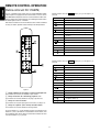
R
Model PM-14mkII User Guide
Integrated Amplifier
69
ENGLISH
WARRANTY
Condizioni di garanzia
For warranty information, contact your local Marantz distributor.
RETAIN YOUR PURCHASE RECEIPT
Your purchase receipt is your permanent record of a valuable purchase.
It should be kept in a safe place to be referred to as necessary for
insurance purposes or when corresponding with Marantz.
L'apparecchio e' garantito per 365 giorni dalla data di acquisto
comprovata da un documento attestante il nominativo del rivenditore e
la data di vendita. La garanzia sara' prestata con la sostituzione o
riparazione gratuita delle parti difettose.
Non sono coperti da garanzia difetti derivanti da uso improprio, errata
installazione, manutenzione effettuata da personale non autorizzato o,
comunque, da circostanze che non possano riferirsi a difetti di
tunzionamento dell'apparecchio. Sono inoltre esclusi dalla garanzia gli
interventi inerenti l'installazione e l'allacciamento agli impianti di
alimentazione.
Gli apparecchi verranno riparati presso i nostri Centri di Assistenza. Le
spese ed i rischi di trasporto sono a carico del cliente.
La casa costruttrice declina ogni responsabilita' per danni diretti o indiretti
provocati dalla inosservanza delle prescrizioni di installazione, uso e
manutenzione dettagliate nel presente manuale.
Per informazioni sull'abbonamento al Servizio Assistenza postgaranzia
e per conoscere l'indirizzo dei Centri Assistenza Marantz rivolgetevi al
nostro servizio consumatori (telefono 1678-20026 - numero verde).
IMPORTANT
When seeking warranty service, it is the responsibility of the consumer
to establish proof and date of purchase. Your purchase receipt or invoice is adequate for such proof.
FOR U.K. ONLY
This undertaking is in addition to a consumer's statutory rights and does
not affect those rights in any way.
FRANÇAIS
GARANTIE
Pour des informations sur la garantie, contacter le distributeur local
Marantz.
CONSERVER L'ATTESTATION D'ACHAT
PORTUGUÊS
L'attestation d'achat est la preuve permanente d'un achat de valeur. La
conserver en lieu sur pour s'y reporter aux fins d'obtention d'une
couverture d'assurance ou dans le cadre de correspondances avec
Marantz.
GARANTIA
Para informações sobre a garantia, contactar o distribuidor Marantz
local.
IMPORTANT
GUARDAR O RECIBO DE COMPRA
Pour l'obtention d'un service couvert par la garantie, il incombe au client d'établir la preuve de l'achat et d'en corroborer la date. Le reçu ou la
facture constituent des preuves suffisantes.
O recibo é o registo permanente da compra que fez. Deve ser guardado
num local seguro, para ser apresentado em questões relacionadas com
o seguro ou para quando tiver de contactar a Marantz.
IMPORTANTE
DEUTSCH
Quando procurar assisténcia técnica ao abrigo da garantia, é da
responsabilidade do consumidor estabelecer a prova e data de compra.
O recibe é prova adequada.
GARANTIE
Bei Garantiefragen wenden Sie sich bitte an Ihren Marantz-Händler.
HEBEN SIE IHRE QUITTING GUT AUF
SVENSKA
Die Quittung dient Ihnen als bleibende Unterlage für Ihren wertvollen
Einkauf Das Aufbewahren der Quittung ist wichtig, da die darin
enthaltenen Angaben für Versicherungswecke oder bei Korrespondenz
mit Marantz angeführt werden müssen.
GARANTI
För information om garantin, kontakta Marantz lokalagent.
SPAR KVITTOT
WICHTIG!
Kvittot är ett inköpsbevis på en värdefull vara. Det skall förvaras säkert
och hänvisas till vid försäkringsfall eller vidkorrespondens mod Marantz.
Bei Garantiefragen muß der Kunde eine Kaufunterlage mit Kaufdatum
vorlegen. Ihren Quittung oder Rechnung ist als Unterlage ausreichend.
VIKTIGT
Fö att garantin skall gälla är det kundens sak att framställa bevis och
datum om köpet. Kvitto eller faktura är tillräokligt bevis fö detta.
NEDERLANDS
GARANTIE
DANSK
Voor inlichtingen omtrent garantie dient u zich tot uw plaatselijke Marantz.
UW KWITANTIE, KASSABON E.D. BEWAREN
GARANTI
Uw kwitantie, kassabon e.d. vormen uw bewijs van aankoop van een
waardevol artikel en dienen op een veilige plaats bewaard te worden
voor evt, verwijzing bijv, in verbend met verzekering of bij correspondentie
met Marantz.
Henvend dem til Deres MARANTZ-forhandler angående inrformation
om garantien.
GEM DERES KVITTERING
Deres købskvittering er Deres varige bevis på et dyrt køb. Den bør
gemmes godt og anvendes som bevis, hvis De vil tegne en forsikring,
eller hvis De kommunikerer med Marantz.
BELANGRIJK
Bij een evt, beroep op de garantie is het de verantwoordelijkheid van de
consument een gedateerd bewijs van aankoop te tonen. Uw kassabon
of factuurzijn voldoende bewijs.
VIGTIGT
Det påhviler forbrugeren at skaffe bevis for købet og købsdatoen, hvis
han eller hun ønsker garantiservice. Deres købskvittering eller faktura
er et fuldgyldigt bevis herpå.
ESPAÑOL
GARANTIA
Para obtener información acerca de la garantia póngase en contacto
con su distribuidor Marantz.
GUARDE SU RECIBO DE COMPRA
Su recibo de compra es su prueba permanente de haber adquirido un
aparato de valor, Este recibo deberá guardarlo en un lugar seguro y
utilizarlo como referencia cuando tenga que hacer uso del seguro o se
ponga en contacto con Marantz.
IMPORTANTE
Cuando solicite el servicio otorgado por la garantia el usuario tiene la
responsabilidad de demonstrar cuá¥do efectuó la compra. En este caso,
su recibo de compra será la prueba apropiada.
1
ENGLISH
ITALIANOI
CONTENTS LIST
ENGLISH
English .................................................................................................................................................................................................................... page 3
Français ................................................................................................................................................................................................................ page 10
Deutsch ................................................................................................................................................................................................................. Seite 17
Nederlands ......................................................................................................................................................................................................... pagina 24
Español ............................................................................................................................................................................................................. pagina 31
Italiano .............................................................................................................................................................................................................. pagina 38
Português .......................................................................................................................................................................................................... página 45
Svenska ................................................................................................................................................................................................................sidan 53
Dansk .................................................................................................................................................................................................................... page 59
Specifications ....................................................................................................................................................................................................... page 66
Figures ................................................................................................................................................................................................................. page 67
CE MARKING
English
The PM-14mkII is in conformity with the EMC directive and low-voltage directive.
Français
Le PM-14mkII est conforme à la directive EMC et à la directive sur les basses tensions.
Deutsch
Das Modell PM-14mkII entspricht den EMC-Richtlinien und den Richtlinien für Niederspannungsgeräte.
Nederlands
De PM-14mkII voldoet aan de EMC eisen en de vereisten voor laag-voltage.
Español
El PM-14mkII está de acuerdo con las normas EMC y las relacionadas con baja tensión.
Italiano
Il PM-14mkII è conforme alle direttive CEE ed a quelle per i bassi voltaggi.
Português
O PM-14mkII conforma com as diretrizes EMC e de baixa voltagem.
Svenska
PM-14mkII är tillverkad i enlighet med EMC direktiven och direktiven för lågvoltsutrusning.
Dansk
Model PM-14mkII er i overensstemmelse med EMC-direktiveet og direktivet om lavspænding.
English
To ventilate the unit, do not install the unit in a rack or bookshelf, and
note the followings.
- Do not insert objects beneath the unit.
- Do not block the ventilation slots at the top of the unit.
Do not place anything about 1 meter above the top panel.
- Make a space of about 0.2 meter around the unit.
Français
Pour que l'appareil puisse être correctement ventilé, ne pas l'installer
dans un meuble ou une bibliothèque et respecter ce qui suit.
- Ne placer aucun objet sous l'appareil.
- Ne pas obstruer les ouães de ventilation du panneau supérieur. Ne
placer aucun objet à moins d'un mètre environ du panneau supérieur.
- Veiller à ce qu'aucun objet ne soit à moins de 0.2 mètre des côtés de
l'appareil.
Deutsch
Um eine einwandfreie Belüftung des Geräts zu gewährleisten, darf das
Gerät nicht in einem Gestell oder Bücherregal aufgestellt werden; die
folgenden Punkte sind besonders zu beachten:
- Keine Gegenstände in das Gerät einführen.
- Die Belüftungsschlitze an der Oberseite des Geräts dürfen nicht
blockiert werden. Darauf achten, daß über dem Gerät ein Freiraum
von mindestens 1 meter vorhanden ist.
- Auf allen Geräteseiten muß ein Zwischenraum von ungefähr 0.2 meter
vorhanden sein.
Nederlands
Installeer het toestel niet in een rek of boekenkast waar de ventilatie
mogelijk wordt gehinderd. Let tevens op de volgende punten:
- Plaats geen onderwerpen onder het toestel.
- Blokkeer de ventilatie-openingen aan de bovenkant van het toestel
niet. Zorg dat er tenminste 1 meter vrije ruimte boven het toestel is.
- Zorg dat er 0.2 meter vrije ruimte rond het toestel is.
Español
Para ventilar la unidad no la instale en una estantería ni estante para
libros, y tenga en cuenta lo siguiente:
- No ponga objetos debajo de la unidad.
- No tape las ranuras de ventilación de la parte superior de la unidad.
No ponga nada a menos de 1 metro por encima del panel superior.
- Deje un espacio de unos 0.2 metro alrededor de la unidad.
Italiano
Perch é l'unità possa essere sempre ben ventilata, non installarla in
scaffali o librerie e tenere presente quanto segue.
- Non inserire oggetti al di sotto dell'unità.
- Non bloccare le fessure di ventilazione sopra l'unità.
Non posare nulla per circa un metro sopra il pannello superiore.
- Lasciare 0.2 metro liberi tutto intorno l'unità.
Português
Para ventilar o aparelho, não instalá-lo dentro duma estante ou algo
similar, e observar as seguintes recomendações:
- Não insertar objectos debaixo do aparelho.
- Não bloquear as aberturas de ventilação na parte de cima do
aparelho. Deixar um espaço completamente livre de cerca de 1 metro
acima do painel superior.
- Deixar um espaço de cerca de 0.2 metro ao redor do aparelho.
Svenska
För att ventilera enheten, ställ den inte i ett ställ eller bokhylla och tänk
på följande.
- Stick inte in föremål under enheten.
- Blockera inte ventialtionshålen ovanpå enheten.
Placera inte någonting närmare än 1 meter ovanför apparaten eller
enheten.
- Se till att det finns omkring 0.2 meter fri plats runt omkring enheten.
Dansk
Anbring ikke apparatet i et rack eller en boghylde, da dette kan bloke
luftcirkulationen omkring apparatet. Iagttag ligeledes følgende:
- Stik ikke genstande ind under apparatet.
- Bloker ikke ventilationsåbningerne ovenpå apparatet.
Anbring ikke noget nærmere end 1 m over apparatets overside,
- Sørg for, at der er et frit område på omkring 0,2 m omkring apparatet.
2
PRECAUTIONS
This section must be read before any connection is made to the mains
supply.
The following precautions should be taken when operating the equipment.
WARNINGS
GENERAL PRECAUTIONS
When setting the equipment ensure that:
— the ventilation holes are not covered
— air is allowed to circulate freely around the equipment
— it is on a vibration free-surface
— it will not be exposed to interference from an external source
— it will not be exposed to excessive heat, cold, moisture or dust
— it will not be exposed to direct sunlight
— it will not be exposed to electrostatic discharges
Never place heavy objects on the equipment.
If a foreign body or water does enter the equipment, contact your nearest dealer or service centre.
Do not pull out the plug by pulling on the mains lead, hold the plug.
It is advisable when leaving the house, or during a thunderstorm, to
disconnect the equipment from the mains supply.
Do not expose the equipment to rain or moisture.
Do not remove the cover from the equipment.
Do not push anything inside the equipment through the ventilation holes.
Do not handle the mains lead with wet hands.
EQUIPMENT MAINS WORKING SETTING
Your Marantz product has been prepared to comply with the household
power and safety requirements that exist in your area.
“/02” Version product can be powered by 230 V AC only.
On the rear panel of the “/01” Version product, a voltage selector (2position) is provided. Be sure to set the voltage selector to the mains
voltage of your area before using the unit.
IMPORTANT: (For UK version only)
This apparatus is fitted with an approved moulded 13 Amp plug.
To change a fuse in this type of plug proceed as follows:
1. Remove fuse cover and fuse.
2. Fix new fuse which should be a BS1362 5A, A.S.T.A. or BSI approved type.
3. Refit the fuse cover.
If the fitted plug is not suitable for your socket outlets, it should be cut off
and an appropriate plug fitted in its place.
If the mains plug contains a fuse, this should have a value of 5A. If a
plug without a fuse is used, the fuse at the distribution board should not
be greater than 5A.
NOTE:
The severed plug must be destroyed to avoid a possible shock hazard
should it be inserted into a 13A socket elsewhere.
CONNECTIONS
(Figure 2)
CONNECTIONS OF TUNER
Connect the output jacks of your stereo tuner to the LINE 1-LINE 3
jaclks of this unit.
CONNECTION OF COMPACT DISC PLAYER
Connect the output jacks of your CD player to the CD jacks of this unit.
HOW TO CONNECT A PLUG
The wires in the mains lead are coloured in accordance with the following code:
BLUE—“NEUTRAL” (“N”)
BROWN—“LIVE” (“L”)
1. The BLUE wire must be connected to the terminal which is marked
with the letter “N” or coloured BLACK.
2. The BROWN wire must be connected to the terminal which is marked
with the letter “L” or coloured RED.
3. Do not connect either wires to the earth terminal in the plug which
is marked by the letter “E” or by the safety earth symbol or coloured
green or green-and-yellow.
Before replacing the plug cover, make certain that the cord grip is
clamped over the sheath of the lead — not simply over the two wires.
CONNECTION OF TURNTABLE
Connect the L (Left) output cord of the turntable to the “L” PHONE jack
of this unit, and connect the R (Right) output cord to the “R” PHONE
jack. Also be sure to connect the turntable's grounding wire to the GND
jack of this unit. The GND jack does not have to be connected if the
turntable is not provided with a grounding wire.
CONNECTION OF DCC/TAPE DECK
Connect the IN (recording input) jacks of the tape deck to the OUT
jacks of this unit, and connect the OUT (playback output) jacks of the
tape deck to the IN jacks of this unit.
CONNECTION OF SPEAKER SYSTEMS
This unit is equipped with a sets of SPEAKER SYSTEM terminals.
• The speakers in the speaker system should have an impedance between 4 and 16 ohms. If speakers with an impedance of less than 4
ohms are connected, the protection circuitry may be activated during
play.
COPYRIGHT
Recording and playback of any material may require consent. For further information refer to the following:
— Copyright Act 1956
— Dramatic and Musical Performers Act 1958
— Performers Protection Acts 1963 and 1972
— any subsequent statutory enactments and orders
• Connect the Right channel speaker to the R terminals, and the Left
channel speaker to the L terminals.
• The output terminaks have positive (+: Red) and negative (–: Black)
polarity, and each speaker slso has the same polarity (+ and –). When
connecting the speaker, be sure to connect the terminals with the
same polarity (+with +, – with –).
ABOUT THIS USER GUIDE
Refer to the Figures on the page 57 at the rear of this user guide. The
numbers on the diagrams correspond to those in the text. All references
to the connections and controls that are printed in BOLD type are as
they appear on the unit.
3
ENGLISH
FOREWORD
NAME AND FUNCTION OF EACH PART
ENGLISH
(Figure 1)
r Volume Control Knob (VOLUME)
A PHONE INPUT jacks
This knob adjusts the volume. Turning the knob to the right ( ), increases the volume. The volume can also be turned up or down with
the remote control unit.
Connect the output jacks of a turntable to these jacks.
B CD PLAYER INPUT jacks
t Balance Control Knob (BALANCE)
Connect the output jacks of a Compact Disc player to these jacks.
This knob is used to correct the imbalance in sound which occurs in
some sources such as stereo broadcasts etc, and to change the output
level of the left or right channel. Note that, if the BALANCE knob is set
fully to the left or right, the sound will not be output of the speaker of the
opposite side.
C LINE 1 – LINE 3 INPUT jacks
These are LINE 1 – LINE 3 input jacks which can be used to connect
the audio outputs of AV components such as TV multiplex/stereo audio
turners, VCRs, and leaserdisc players.
y Source Direct Switch (SOURCE DIRECT)
D TAPE 1/TAPE 2 IN/OUT jacks
Pressing this switch causes the signal to be transmitted without passing through the balance and tone control circuitry, enabling you to further enjoy high-grade sound.
(The sound can not be adjusted with the BALANCE, BASS and TREBLE
knobs.)
Connect the play (output) jacks and record (input) jacks of tape decks
to these jacks.
Up to these tape decks can be connected.
NOTE:
When a surround processor or graphic equalizer is used, it must be
connected to the TAPE 1 jacks.
u Tone Control Knobs (TREBLE, BASS)
These knobs adjust the high and low frequency ranges. The strength of
each frequency range is controlled by turning the knobs. Each frequency
is boosted by turning the knob clockwise “+“ and reduced by turning it
counterclockwise “–”.
TREBLE: Adjusts the tone of the high frequency range.
BASS:
Adjusts the tone of the low frequency range.
E MM/MC SELECTOR switch
When the INPUT SELECTOR is set to PHONE, the type of cartridge
used on the turntable can be selected between MM (Moving Magnet)
and MC (Moving Coil) using this switch.
Set this switch according to the cartridge used on the turntable.
MC is selected when the switch is set to the low position.
i Power Supply Switch (POWER)
F GND (GROUND) terminal
Pressing this switch turns the power on and pressing it again turns the
power off.
The light of the warm-up meter lights when the power is turned on. The
light goes out when the power is turned off.
Connect the grounding wire from the turntable to this terminal.
G SPEAKER SYSTEMS
Connect your speaker system to these terminals.
o Headphone Jack (PHONES)
H PRE-OUTPUT terminal
A standard stereo headphone plug can be used in this jack.
Output jack for connection to extension power-amp, mixer or similar.
!0 Speaker Switch (SPEAKERS)
This switch selects the speaker system.
The SYSTEM A terminal and SYSTEM B terminal are always connected.
Turn the switch off when only using the headphones.
q Input Selector Switch (INPUT SELECTOR)
This switch is used to select the program source (PHONO, CD, LINE 1,
LINE 2, LINE 3, TAPE 1, or TAPE 2) to be recorded or played.
!1 IR sensor window
w CD Selector Switch (CD SELECTOR)
This is the window which receives the infrared remote control signals.
Point the remote control towards this window and correctly send the
signals.
When the input selector switch q is set to CD, this switch selects the
program sources connected to CD UNBALANCED and CD BALANCED
on the rear panel.
When the switch is not pushed ( ), CD UNBALANCED is selected.
When the switch is pushed ( ), CD BALANCED is selected.
!2 Record Selector Switch (REC SELECTOR)
This switch is used to select whether the recording is done between the
tape decks with the COPY function or with a signal output to the REC
OUT terminal.
e Warm-up Meter
This meter is used to check the device’s warm-up condition.
The full sound quality of audio equipment can not be obtained immediately after the power supply is turned on. It is necessary to sufficiently
warm-up the device so that it can exhibit its full potential. After turning
the power supply on, as time passes the temperature of each part of
the device will become the same. At the same time, the electrolytic
condenser is also activated.
Shortly after the power supply is turned on, the meter needle rises, and
reaches approximately 2/3 of the meter range after approximately 30
minutes. At this stage, the warming-up is almost completed, and you
can enjoy listening to music with the full acoustic quality of the device.
The position of the meter needle immediately after the power supply is
turned on and during the warming-up, and the amount of time necessary for the warming-up differ depending on the room temperature and
ventilation of the room in which the device is used.
4
TAPE DECK OPERATION
CD
CD
21
PHONO
LINE
19
25
1
INTEGRATED AMPLIFIER
LINE
21
17
PHONO
LINE
INTEGRATED AMPLIFIER
14
LINE
32
19
25
1
15
29
PM-14mkII
2
17
15
29
PM-14mkII
2
14
32
13
52
4
13
38
38
LINE
LINE
3
12
12
3
10
40
10
40
48
48
CD-R
TEMP
4
TEMP
66
66
2
BAL.
UNBAL.
TAPE
7
7
52
CD-R
2
BAL.
UNBAL.
TAPE
0
(-dB)
0
(-dB)
CD SELECTOR
INPUT SELECTOR
CD SELECTOR
INPUT SELECTOR
SELECTOR
BALANCE
OFF
TAPE
TAPE
CD-R
SPEAKERS
PHONES
POWER
BASS
B
LINE 1
0
0
OFF
CD-R
TAPE
TAPE
BALANCE
CD-R
SPEAKERS
LINE 2
4
4
4
PHONES
POWER
B
LINE 1
OFF
6 +
– 6
(dB)
6 +
– 6
(dB)
0
SOURCE
DIRECT
4
2
2
2
2
A+B
LINE 2
OFF
LEFT
4
6 +
– 6
(dB)
PHONO
ON
4
4
6 +
– 6
(dB)
ON
OFF
LEFT
RIGHT
RIGHT
Playing a record
1
2
3
TREBLE
0
4
LINE 3
LINE 3
PHONO
BASS
A
CD
2
2
2
2
A+B
SELECTOR
OFF
SOURCE
DIRECT
TREBLE
A
CD
COPY
COPY
VOLUME
VOLUME
REC
REC
CD-R
Playing a Tape
1
Set the INPUT SELECTOR switch q to the PHONO position.
Select the tape deck to be used (TAPE 1 or TAPE 2) with the
INPUT SELECTOR switch q.
Operate the record player.
2
Adjust the volume with the VOLUME knob r.
Operate the tape deck and play a tape which has something
recorded on it.
3
Note:
• Set the volume to the minimum when exchanging the record player
cartridge or lowering the stylus onto a record.
Recording on a Tape
Use the following procedure to record a source such as a record player,
tuner, CD player, etc onto a tape.
[When recording from a CD player]
• Do not subject the record player to vibrations while playing records.
Vibrations may cause the stylus to jump and scratch the record.
• If the record player is placed near the speakers, howling may occur
and this will prevent the volume from being increased.
1
2
3
• Do not turn the power supply off while the stylus is still on the record.
•
Playing a CD
1
2
3
Adjust the volume with the VOLUME knob r.
Set the REC SELECTOR switch !2 to the CD position.
Start playing the program source.
Operate the tape deck and start recording.
The source to be recorded can be selected with the REC SELECTOR
switch !2 regardless of the setting of the INPUT SELECTOR switch q.
Set the INPUT SELECTOR switch q to the CD position.
To record the record player
signal
Operate the component connected to the selected jack.
.......... PHONO position
Adjust the volume with the VOLUME knob r.
To stop the output to the tape .......... OFF position
when recording is not
required
To record the CD signal
Playing from LINE 1 to LINE 3
Playing a component which is connected to one of the LINE 1 to LINE 3
jacks on the rear panel.
1
To record the signal
connected to one of LINE 1
through LINE 3
Set the INPUT SELECTOR switch q to one of the LINE 1 to
LINE 3 positions.
2
3
.......... CD position
.......... Set the REC SELECTOR
switch to one of the LINE 1
through LINE 3 positions.
Operate the component connected to the selected jack.
Adjust the volume with the VOLUME knob r.
Using the REC SELECTOR switch !2 to copy a prerecorded tape
Regardless of the program source selected with the INPUT SELECTOR switch q, the REC SELECTOR switch !2 can be switched to 1 to
2 or 2 to 1 to copy from TAPE 1 to TAPE 2 or from TAPE 2 to TAPE 1.
• While copying tapes, you can listen to another program source by
selecting it with the INPUT SELECTOR switch q.
• TAPE COPY 1 to 2 allows you to copy the signal from the tape deck
connected to TAPE 1 to the tape deck connected to TAPE 2. TAPE
COPY 2 to 1 allows you to copy the signal from the tape deck connected to TAPE 2 to the tape deck connected to TAPE 1.
5
ENGLISH
PLAY OPERATION
ENGLISH
REMOTE CONTROL OPERATION
(Remote control unit: RC-17mkIIPM)
Button functions when the TAPE 1 button (see z of the figure 3) is
pressed:
The RC-17mkIIPM remote control unit can control MARANTZ audio/
video components equipped with an infrared remote sensor as well as
other MARANTZ components which are connected with the above components through the remote control bus. The following illustration shows
the button layout of the RC-17mkIIPM.
Note that the functions of the PM-14mkII that can be remote controlled
are only the volume up/down control and input selection operations.
Button
Function
Play
Fast forward
Rewind
Play direction change
Stop
REPEAT
PHONO
CD
RANDOM
CD-R
LINE 1/TUNER
+/A
TAPE
LINE 2
OPEN/CLOSE
Open/close (limited models only)
+
Deck A
–
Deck B
Skip forward to next music
−/B
Skip backward to previous music
LINE 3
1
2
3
4
5
6
7
8
9
REPEAT
Reverse mode
RANDOM
Not used.
VOL
Amplifier volume Up
VOL
Amplifier volume Down
0
Button functions when the TAPE 2 button (see z of the figure 3) is
pressed:
Button
Function
OPEN/CLOSE
Play
VOLUME
Fast forward
Rewind
Play direction change
Stop
OPEN/CLOSE
Open/close
+
Deck A
–
Deck B
Skip forward to next music
Figure 3
Skip backward to previous music
z Group of buttons for selecting the connected components
These buttons are used as the amplifier’s input selector.
x Group of buttons for controlling playback, etc.
These buttons are used to control the CD player, tape deck, etc.
c Group of numeric buttons
These buttons are used to enter figures for the tuner, CD player, etc.
v Group of amplifier (PM-14mkII) control buttons
These buttons are used to control the listening volume.
Pressing a button in z (except PHONO) changes the functions of the
buttons in x and c to match the selected device. For the details, refer
to the following tables which show the function of the buttons for when
each of the buttons in z is pressed.
6
REPEAT
Not used.
RANDOM
Not used.
VOL
Amplifier volume Up
VOL
Amplifier volume Down
Button
Button functions when the LINE 1 (TUNER) button (see z of the
figure 3) is pressed:
Function
Button
Function
Play
Not used.
Fast forward
Frequency Up
Rewind
Frequency Down
Not used.
Not used.
Stop
Not used.
OPEN/CLOSE
Open/close
OPEN/CLOSE
Not used.
+
Disc Up (changer-equipped model only)
+
Preset Up
–
Disc Down (changer-equipped model only)
–
Preset Down
Skip forward to next music
Programme type Up
Skip backward to previous music
Programme type Down
REPEAT
Repeat
REPEAT
Not used.
RANDOM
Random play
RANDOM
Not used.
VOL
Amplifier volume Up
VOL
Amplifier volume Up
VOL
Amplifier volume Down
VOL
Amplifier volume Down
Button functions when the LINE 2 (TV) button (see z of the figure 3)
is pressed:
Button
Button functions when the LINE 3 (DVD) button (see z of the figure
3) is pressed:
Function
Button
Function
VCR play
Play
VCR fast forward
Fast forward
VCR rewind
Rewind
Not used.
Not used.
VCR stop
Stop
OPEN/CLOSE
VCR eject
OPEN/CLOSE
Eject
+
Channel/program Up
+
Not used.
–
Channel/program Down
–
Not used.
VCR double-speed forward
Skip forward to next music
VCR double-speed backward
Skip backward to previous music
REPEAT
Not used.
REPEAT
Repeat
RANDOM
Not used.
RANDOM
Random play
VOL
Amplifier volume Up
VOL
Amplifier volume Up
VOL
Amplifier volume Down
VOL
Amplifier volume Down
7
ENGLISH
Button functions when the CD button (see z of the figure 3) is pressed:
PRE OUT, MAIN IN TERMINALS
How to use the remote control unit
ENGLISH
1. Remote control unit
The distance between the signal transmitter of the remote control unit
(RC-17mkIIPM) and the IR SENSOR of the integrated amplifier (PM14mkII) should be less than about 5 meters. To ensure remote control,
the remote control unit should be pointed accurately toward the IR SENSOR and there should be no obstacle between the remote control unit
and the IR SENSOR.
When shipped from the factory, the COUPLED/SEPARATE switch is
set to the COUPLED position. In this condition, the PRE OUT (pre amp
output terminal) and MAIN IN (main amp input terminal) are internally
connected, and can be used as the pre main amp. Therefore, it is not
necessary to insert a short bar in the terminals.
If the COUPLED/SEPARATE switch is set to the SEPARATE position,
the PRE OUT (pre amp output terminal) and MAIN IN (main amp input
terminal) can be used individually.
Connect peripheral equipment such as power amps, channel dividers,
sound effectors, etc to the PRE OUT (pre amp output terminal).
Connect the pre amp to the MAIN IN (main amp input terminal).
Remote controllable range
Stereo integrated amplifier (PM-14mkII)
The diagram below is an example of connecting a channel divider and
expanding it into a multi amp drive.
Approx. 5 m
REPEA
T
RANDO
PHONO
M
+/
+/
TAPE
A
1
TAPE
A
CD
CD UNBALANCED
LINE
1/TUNE
R
2
LINE
R
2/TV
1
R
L
+
L
LINE
3/DVD
2
4
6
8
0
9
R
–
–
L
Remote control unit (RC-17mkIIPM)
OUT
IN
LINE
2
GND
REMOTE CONTROL
+
LINE
1
/TUNER
3
5
7
OPEN
/CLOSE
VOLUM
E
CD BALANCED
R
PUSH
PUSH
L
R
LINE
3
IN
SELECTOR
CD-R
MM
MC
CONNECTION
OUT
1 – GND 2 – COLD 3 – HOT
R
IN
TAPE
+
L
R
L
L
MAIN IN
PHONO
R
–
–
L
+
SPEAKER SYSTEMS
SYSTEM A
: 4 – 16 OHMS
SYSTEM B
: 4 – 16 OHMS
S Y S T E M A + B : 8 – 16 OHMS
COUPLED
OUT
R
PRE OUT
SEPARATE
AC
2. Loading batteries
The service life of the batteries used in the remote control unit is about
1 year under normal use.
Remove the batteries when the remote control unit is not to be used for
a long period of time. Replace batteries early whenever they seem to
be weakened.
q Remove the back cover.
INLET
PRE OUT
SEPARATE
R
L
COUPLED
R
L
MAIN IN
Other power amplifier
w Insert batteries with correct and polarity.
e Slide close the battery cover until it clicks.
INPUT
HIGH
OUTPUT
L
R
R
Channel divider
Improper use of batteries may cause the risk of fluid leakage or
explosion.
Be specially careful in the following points.
q Insert the batteries with the correct and polarity as indicated
inside the battery case.
w Do not use a brand-new battery and used battery together.
e Dry cell batteries may produce different voltages even when
their shapes are the same. Do not use different types of batteries together.
r Some batteries are rechargeable and some are not. Be sure
to read the caution and instructions described on each battery.
t Used batteries should be disposed of in compliance with the
treatment method specified for your local area.
8
LOW
OUTPUT
L
TROUBLESHOOTING
ENGLISH
In case of trouble with the set, first check the following before calling for
service. What seems to be a serious malfunction is often due to a simple
operation mistake.
If the trouble still persists after checking, please consult your dealer or
nearest MARANTZ service agent.
The amplifier does not function and the indicator does not light.
1. Check if the power cord is plugged properly into an AC power outlet.
The indicator lights but the amplifier will not function.
1. Check the settings of the SELECTOR switches, VOLUME control
and SPEAKERS switch.
Sound is produced only from one of the speaker systems.
1. Check the setting of the BALANCE control.
2. Turn power of the set off and change the connections of the left and
right speaker systems. If sound is still not output from the same
speaker system, check its connection cord or the speaker system
itself.
Sound is not produced at all.
1. Check the settings of the SELECTOR switches.
2. Check the SPEAKERS switch is pressed in.
3. Check that the speaker cords are connected properly.
4. Check that the connection cords with RCA pin plugs are connected
properly.
Sound from the analog turntable is not output or very noisy
(hum noise).
1. Check that the connection to the PHONO jack is made properly.
2. Connect the grounding wire of the turntable to the GND terminal on
the rear panel of the amplifier set. If it has already been connected,
try removing it.
3. Check that the cartridge is attached properly to the tone arm.
4. Remove the power plug of the turntable from the power outlet and
insert it again by inverting the relationship of the left and right blades
with respect to the power outlet slots.
9
TECHNICAL SPECIFICATIONS (DIN)
Rated power output (20 Hz to 20 kHz, 2CH simultaneous drive) ...................................................................................................... 100 W x 2 (8 Ω load)
160 W x 2 (6 Ω load)
200 W x 2 (4 Ω load)
Total harmonic distortion (20 Hz to 20 kHz, 2CH drive, 8 Ω load) .......................................................................................................................... 0.01 %
Cross-modulation distortion (SMPTE) .................................................................................................................................................................... 0.01 %
Output bandwidth (8 h load, 0.04 %) ........................................................................................................................................................ 10 Hz to 60 kHz
Frequency response (CD, SOURCE DIRECT) .......................................................................................................................... 5 Hz to 60 kHz, +0/–1 dB
Damping factor (8 h load, 20 Hz to 10 kHz) ................................................................................................................................................................. 120
Input sensitivity/input impedance
PHONE (MC) ........................................................................................................................................................................................ 290 µV/100 Ω
PHONE (MM) ....................................................................................................................................................................................... 2.6 mV/47 kΩ
HIGH LEVEL ....................................................................................................................................................................................... 280 mV/10 kΩ
MAIN IN ................................................................................................................................................................................................. 1.8 V/100 kΩ
Output voltage/output impedance
PRE OUT ................................................................................................................................................................................................. 1.8 V/250 Ω
Maximum allowable PHONE input (1 kHz)
MC .................................................................................................................................................................................................................... 11 mV
MM .................................................................................................................................................................................................................. 100 mV
RIAA deviation (20 Hz to 20 kHz) ......................................................................................................................................................................... ±0.2 dB
S/N (IHF A network, input shorted)
PHONE (MC) ..................................................................................................................................................................................................... 76 dB
PHONE (MM) .................................................................................................................................................................................................... 90 dB
HIGH LEVEL ................................................................................................................................................................................................... 110 dB
Tone control
BASS (100 Hz) .................................................................................................................................................................................................. ± 8 dB
TREBLE (10 kHz) .............................................................................................................................................................................................. ± 8 dB
Supply voltage .......................................................................................................................................................................................... 230 V AC, 50 Hz
Power consumption .................................................................................................................................................................................................. 300 W
Dimensions
Width ............................................................................................................................................................................................................. 458 mm
Height ............................................................................................................................................................................................................ 166 mm
Depth ............................................................................................................................................................................................................. 464 mm
Weight ............................................................................................................................................................................................................. 23.0 kg
Accessories
Remote control unit (RC-17PM) ................................................................................................................................................................................ 1
Dimensions
Width ......................................................................................................................................................................................................... 44 mm
Heigh ....................................................................................................................................................................................................... 239 mm
Depth ...................................................................................................................................................................................................... 17.5 mm
Weight (without batteries) ............................................................................................................................................................................ 189 g
SUM-4 (R03/ "AAA" size) dry cell battery .......................................................................................................................................................... 2
Design and specifications are subject to change without notice.
66
CD UNBALANCED
R
R
L
+
L
R
–
–
REMOTE CONTROL
+
L
LINE
2
GND
OUT
IN
LINE
1
/TUNER
CD BALANCED
R
PUSH
L
PUSH
R
LINE
3
IN
SELECTOR
CD-R
CONNECTION
OUT
MM
MC
1 – GND 2 – COLD 3 – HOT
R
IN
TAPE
+
L
R
L
L
MAIN IN
PHONO
R
–
–
+
L
SPEAKER SYSTEMS
SYSTEM A
: 4 – 16 OHMS
SYSTEM B
: 4 – 16 OHMS
S Y S T E M A + B : 8 – 16 OHMS
COUPLED
OUT
R
PRE OUT
SEPARATE
AC
INLET
CD
21
PHONO
LINE
19
25
1
INTEGRATED AMPLIFIER
LINE
17
15
29
PM-14mkII
14
32
2
13
38
LINE
3
12
10
40
48
CD-R
7
52
4
TEMP
66
2
BAL.
UNBAL.
TAPE
0
(-dB)
CD SELECTOR
INPUT SELECTOR
REC
VOLUME
SELECTOR
BALANCE
OFF
CD-R
TAPE
TAPE
CD-R
COPY
SPEAKERS
PHONES
POWER
BASS
SOURCE
DIRECT
TREBLE
A
CD
B
LINE 1
0
0
OFF
A+B
LINE 2
4
LINE 3
4
6 +
– 6
(dB)
PHONO
Figure 1
67
2
2
2
2
4
4
6 +
– 6
(dB)
ON
OFF
LEFT
RIGHT
SPEAKER CONNECTIONS
This unit can accept the connection of speakers equipped with
dedicated terminals for bi-wire connection.
Bi-wire connection is possible by connecting each speaker to both
the SYSTEM A and SYSTEM B terminals.
Speakers which do not use bi-wire connection or which are not
equipped with bi-wire connection terminals can be connected to either
SYSTEM A or SYSTEM B terminals.
However, in this case, it is recommended to use the SYSTEM A
terminals in consideration of sound quality.
• Speakers connected to this unit should have an impedance in the
range of 4 to 16 ohms. If speakers with an impedance of less than
4 ohms are connected, the internal protection circuitry may switch
on to cut the output during operation.
• This unit’s speaker terminals are separated into positive ( : red)
and negative ( : white) polarity. The terminals on the speakers
are also separated by polarity (
and ). When making connections, be sure to connect terminals of the same polarity (
to ,
to ).
NOTE:
In case of using two sets of speakers simultaneously, make sure the
impedance of each speaker is 8 ohms or greater. If speakers with an
impedance of less than 8 ohms are connected, the internal protection
circuitry may switch on causing normal stereo operation to be
prevented.
SPEAKER SYSTEM
TUNER, etc
CD Recorder
(To LINE INPUT
jacks)
CD PLAYER
VCR, etc
Connect the R output
terminal to the right channel
speaker and the L output
terminal to the left channel
speaker.
CD PLAYER
(To LINE
OUTPUT
jacks)
(To LINE
OUTPUT
jacks)
L
R
To BALANCED
connector
(XLR connector)
REMOTE CONTROL jacks
By connecting this unit with a MARANTZ
component equipped with the remote
control (D-BUS) jacks, both components
can be remote control as a system.
For details of the remote control function,
read the user guide of the connected
component.
SPEAKER CORD CONNECTION
Strip coating from
the end of cord.
Twist conduc
CD UNBALANCED
R
R
L
+
L
R
–
–
L
REMOTE CONTROL
+
LINE
2
GND
OUT
IN
LINE
1
/TUNER
CD BALANCED
R
PUSH
L
PUSH
R
LINE
3
Tu r n t h e t e r m i n a l
counterclockwise to
loosen.
IN
SELECTOR
PHONO SELECTOR switch
CD-R
MM
MC
Set according to the type of cartridge used
withthe turntable
MM (Moving Magnet) type
Leave the switch in the out ( ) position.
MC (Moving Coil) type
Set the switch to the pressed-in ( ) position.
OUT
CONNECTION
1 – GND 2 – COLD 3 – HOT
TAPE
OUT
R
PRE OUT
SEPARATE
R
IN
L
COUPLED
R
L
L
MAIN IN
PHONO
+
R
–
–
L
+
Banana
plug
INLET
Tu r n t h e t e r m i n a l
counterclockwise to
loosen.
To AC power outlet
Connect a power amp,
channel divider, sound
effector, pre main amp,
etc to the PRE OUT
terminal.
Connect the pre amp to
the MAIN IN terminal.
For the details, refer to
page 8.
CD BALANCED terminal
1. The XLR connector is used in the BALANCED
terminal.
2. For professional usage, there are two types of XLR
connector connection method.
L
(To LINE INPUT
jacks)
Turn the terminal
clockwise to
clamp speaker
cord.
• Banana plug can also be used as shown
SPEAKER SYSTEMS
SYSTEM A
: 4 – 16 OHMS
SYSTEM B
: 4 – 16 OHMS
S Y S T E M A + B : 8 – 16 OHMS
AC
(To LINE OUTPUT
jacks)
Insert the conductors.
R
A USA system (wPIN=COLD ePIN=HOT)
COLD
(To LINE OUTPUT
jacks)
HOT
2
1
3
HOT
GND
Insert the banana plug
Turn the terminal
clockwise to clamp
banana plug
3. The USA system is used in this device (PM-14mkII).
When using an XLR connector cable and playing
a CD player etc which uses the European system,
the phase is reversed. In this case, as shown in
the diagram below, reconnect the q PIN and w
PIN of one side of the XLR connector to make it
the USA system.
GND
HOT
(XLR)
TURNTABLE
Connect the output cord
from an analog record
turntable.
COLD
B European system (wPIN=HOT ePIN=COLD)
TAPE DECK
DVD PLAYER, etc
SPEAKER SYSTEM
HOT
HOT
2
68
GND
GND
(XLR)
1
1
3
HOT
GND
(XLR)
PM-14mkII (USA system)
2
GND
1
3
COLD
(XLR)
(European system)
1
3
COLD
• The TAPE 1 and TAPE 2 program source can also accept the connections with the audio output/input jacks of VCR, etc
2
69
The above will ensure that the equipment is played
with the correct phase.
COUNTRY
ALGERIE
ARMENIA
AUSTRALIA
AUSTRIA
BAHREIN
BANGLADESH
BELGIUM
BULGARIA
CANADA
CHINA
CYPRUS
CZECH REPUBLIC
DENMARK
DUBAI
EGYPT
ESTONIA
F.Y.R.O.M.
FINLAND
FRANCE
GERMANY
GREECE
HEADQUARTERS EUROPE:
HONG KONG
HUNGARY
ICELAND
INDIA
IRAN
IRELAND
ISRAEL
ITALY
IVORY COAST
JAPAN
KOREA
KUWAIT
LATVIA
LEBANON
LITHUANIA
MALAYSIA
MALTA
MAURITIUS
MILITARY MARKET EUROPE
NETHERLANDS
NEW ZEALAND
NORWAY
OMAN
POLAND
PORTUGAL
PROFESSIONAL EUROPE
PROFESSIONAL U.S.A.
QATAR
REUNION
ROMANIA
RUSSIA
SAUDI ARABIA
SINGAPORE
SLOVAKIA
SLOVENIA
SOUTH AFRICA
SPAIN
SRI LANKA
SWEDEN
SWITZERLAND
SYRIA
TAHITI
TAIWAN
THAILAND
TUNESIA
TURKEY
U.K.
U.S.A.
YUGOSLAVIA
EXPORT
www.marantz.com
COMPANY
Azur 2000
NGYIG Ltd.
Jamo Australia Pty. Ltd.,
Huber & Prohaska GmbH
Ambassador Stores
Target
Van der Heyden Audio N.V.
Ariescommerce GmbH
Lenbrook Industries Limited
Guang Chang Audio International Co., Ltd.
Empire Hifi systems Ltd.
Audio International
Audio Nord
V.V.& SONS
Solimco
HiFi Club Estonia
T.P. KODI
Audio Nord
Marantz France
Marantz Deutschland
Adamco S.A.
Marantz Europe B.V.
Marantz Asia Ltd.
Infovox Ltd.
ID Electronics Ltd.
NOVA Audio Private
Home Co.
Marantz Ireland
Elmor Ltd.
Marantz Italy
Hifivoir
Marantz Japan Inc.
Mk Enterprises Ltd.
alAlamiah Electronics Intl.
Ace Ltd.
AZ Electronics S.A., 1,
Accapella Ltd.
Wo Kee Hong Electronics Sdn. Bhd.
Doneo Co Ltd.
SKR Electronics Ltd.
PASCO GmbH
Marantz Domestic Sales
Wildash Audio Systems
Audio Nord
Mustafa & Jawad Trading CO.
Philips Polska Sp. z.o.o.
Corel2
Marantz Professional Products
Marantz Professional Products
Almana & Partners W.W.L.
Vision +
Nova Music Entertainment
Absolute Audio
Adawlia Univ. Electr. Apl
Forward Marketing (S) Pte. Ltd.
Bis Audio s.r.o.
Bofex
Coherent Imports (PTY) Ltd.
Marantz Spain
The listening Room
Audio Nord
Sound Company AG
Hamzeh & Partners
Covecolor
Pai-Yuing Co. Ltd.
MRZ Standard Co. Ltd.
Societe EDEVIG
Türk Philips Ticaret A.S.
Marantz Hifi UK Ltd.
Marantz America Inc.
ITM Company
Marantz Domestic Sales
ADDRESS
8, Lotissement Ben Hatadi, Alger, Algerie
47 A/75 St. Lalaiants, 375000 Yerevan, Armenia
24 Lionel Road, Mt. Waverley, VIC 3149, Australia
Taborstraße 95 / Ladestraße 1, Gebäude Hangartner, A-1200 Wien, Austria
P.O. Box 237,141, Government Avenue, Manama,Bahrein
1078, Ramjoy Mohanja Lane Asadgonj, Chittagong 4000, Bangladesh
Brusselbaan 278, 9320 Erembodegem, Belgium
Makedonia Blvd. 16, 1606 Sofia, Bulgaria
633 Granite Court, Pickering, Ontario
No.38 Yushan Road, ShiQiao, Pan Yu, Guang Dong, China
P.O. Box 5604, Nicosia, Cyprus
Sokolska 41, 67902 Rajecko, OKR,Blansko, Czech Republic
Dali Allé 1, 9610 Noerager, Denmark
P.O. Box 105, Dubai, U.A.E.
9, El Attibaa St. Doki, Cairo, Egypt
Ehte 4, 90503 Haapsalu, Estonia
ul.Cedomir Kantargiev 21a, Skopje, Former Yugoslavian Republic of Macedonija
Uudenmaankatu 4-6, Helsinki SF-00120, Finland
A division of Marantz Europe B.V., P.O. Box 301, 92 156 Suresnes Cedex, France
Hakenbusch 3, 49078 Osnabrück, Germany
188, Hippocratous Street, 11471 Athens, Greece
Building SFF-2, P.O. Box 80002, 5600 JB Eindhoven, The Netherlands
Unit 1706, Metroplaza II, 223 Hing Fong Road, Kwai Fong, N.T., Kowloon, Hong Kong
Terez Krt.31, 1067 Budapest, Hungary
Armula 38, 108 Reykjavik, Iceland
8,Punam Co-op.Society 29/30 Road#5, Union Park MUMBAI 400052, India
5th floor no 878 Philips Building Enghelab ave, P.O. 11365/7844 Tehran, Iran
Clonskeagh, Dublin 14, Ireland
52 Heh Beiyar Street, Kikar Hamedina, Tel Aviv, Israel
Via Casati 23, 20052 Monza (Milano), Italy, Servizio Consumatori 1678-20026, Numero Verde
B.P. 2428, Abidjan 01, Ivory Coast
35-1 Sagami Ohno 7-Chome, Sagamihara-shi, Kanagawa 228-8505, Japan
121-210, 2F Shinhan Bldg., 247-17 Seokyo-dong, Mapo-ku, Seoul, Korea
P.O. Box 8196, Salmiah 22052, Kuwait
61, LacPlesa Str., Riga LV 1011, Latvia
P.O. Box 11 2833, Beirut, Lebanon
Ausros, Vartu G/5, Pasazo SKG., 2001 Vilnius, Lithuania
102 Jalan SS 21/35, Damansara Utama, 47400 Petaling Jaya, Selangordarul Ehsan, Malaysia
78 The Strand, Sliema SLM07, Malta
P.O. Box 685, Bell Village, Port Louis, Mauritius
PO BOX 1280, Sandhausen 69200, Germany
A division of Marantz Europe B.V., Building SFF2, P.O. Box 80002, 5600 JB Eindhoven, The Netherlands
14 Malvern Road, Mt. Albert, Auckland, New Zealand
Sandkerveien 64, Oslo 0483, Norway
P.O. Box 1918, Ruwi, Oman
Al.Jerozolimskie 195b, 02 222 Warszawa, Poland
Comércio de Electrónica Lda., Av. Luís Bívar, No 85 A, 1050 Lisboa, Portugal
Kingsbridge House, Padbury Oaks, 575-583 Bath Road, Longford, Middlesex UB7 0EH, U.K.
Distributed by: Superscope Technologies Inc., 1000 Corporate Blvd. Ste.D, Aurora, Illino
P.O. Box 49, Doha, Qatar
180 Rue du Marechal Leclerc, 97400 Saint Denis, Ile de la Reunion
5, Zagazului Str. Bl.1G,apt.18, sector 1,Bucharest, Romania
7/2, Montazhnaya Street, 107497 Moscow, Russia
P.O. Box 2154, Alkhobar 31952, Saudi Arabia
Wo Kee Hong Centre, 29 Leng Kee Road, Singapore 159099, Singapore
Nam. SNP 10, 96001 Zvolem, Slovakia
Smartinska 152, HALA V/3, 61000 Ljubljana, Slovenia
P.O. Box 1614, Alberton, 1450, South Africa
Martinez Villergas 2, Apartado 2065, Madrid 28027, Spain
Mezzanine Floor, The Landmark 385, Galle Road, Colombo - 3, Sri Lanka
Almedalsvagen 4, Gotenborg 402-23, Sweden
Postfach, 8010 Zürich, Switzerland
Hafez Ibrahim Str. No 117, Damascus Shalan, Syria
Av. Prince Hinoi, Cours de l'union sacré, P.O. Box 2334, Papeete, Tahiti
6th No 148 Sung Kiang Road, Taipei 10429, Taiwan R.O.C.
746-750 Mahachai Road, Wangburapa, Bangkok 10200, Thailand
40, Avenue du Golfe Arabe, El Menzah, 1004, Tunesia
Yukari Dudullu Organize sanayi Bolgesi, 2.Cadde no.28, 81260 Umraniye-Istanbul, Turkey
Kingsbridge House, Padbury Oaks, 575-583 Bath Road, Longford, Middlesex UB7 0EH, U.K.
440 Medinah Road, Roselle, IL 60172, U.S.A.
Omladinskih Brigada 86, 11070 Belgrade, Yugoslavia
A division of Marantz Europe BV,Building SFF2, P.O. Box 80002, 5600 JB Eindhoven, TheThe Netherlands
is a registered trademark.
02/01 MITi 318J851312
Printed in Japan
68