1
4434 en - 2011.07 / c
Armature
terminals
A1
A2
n
e give
is to ber
l
a
u
n
a
s
This mto the end u
Control connections
DC fuse
for 4Q only
RLY2
Auxillary connections
E1
E3
L12 L11
F+
F-
21 22 23 24 25 26 27 28 29 30 31
61 62 63
24V
Drive
enable
Field
on / off
Fan supply (where applicable)
Motor
MENTOR MP
Short form guide
General Information
The manufacturer accepts no liability for any consequences resulting from inappropriate, negligent or
incorrect installation or adjustment of the optional operating parameters of the equipment or from
mismatching the variable speed drive with the motor.
The contents of this guide are believed to be correct at the time of printing. In the interests of a commitment
to a policy of continuous development and improvement, the manufacturer reserves the right to change the
specification of the product or its performance, or the contents of the guide, without notice.
All rights reserved. No parts of this guide may be reproduced or transmitted in any form or by any means,
electrical or mechanical including photocopying, recording or by an information storage or retrieval system,
without permission in writing from the publisher.
Drive software version
This product is supplied with the latest software version. If this drive is to be connected to an existing system
or machine, all drive software versions should be verified to confirm the same functionality as drives of the
same model already present. This may also apply to drives returned from LEROY-SOMER.
If there is any doubt please contact LEROY-SOMER.
The software version of the drive can be checked by looking at Pr 11.29 (di14/0.49) and Pr 11.34. This
takes the form of xx.yy.zz where Pr 11.29 (di14/0.49) displays xx.yy and Pr 11.34 displays zz. (e.g. for
software version 01.01.00, Pr 11.29 (di14/0.49) = 1.01 and Pr 11.34 displays 0).
Environmental statement
LEROY-SOMER is committed to minimising the environmental impacts of its manufacturing operations and
of its products throughout their life cycle. To this end, we operate an Environmental Management System
(EMS) which is certified to the International Standard ISO 14001. Further information on the EMS, our
Environmental Policy and other relevant information is available on request, or can be found at
www.leroy-somer.com.
The electronic variable-speed drives manufactured by LEROY-SOMER have the potential to save energy
and (through increased machine/process efficiency) reduce raw material consumption and scrap
throughout their long working lifetime. In typical applications, these positive environmental effects far
outweigh the negative impacts of product manufacture and end-of-life disposal.
Nevertheless, when the products eventually reach the end of their useful life, they must not be discarded
but should instead be recycled by a specialist recycler of electronic equipment. Recyclers will find the
products easy to dismantle into their major component parts for efficient recycling. Many parts snap
together and can be separated without the use of tools, whilst other parts are secured with conventional
fasteners. Virtually all parts of the product are suitable for recycling.
Product packaging is of good quality and can be re-used. Large products are packed in wooden crates,
while smaller products come in strong cardboard cartons which themselves have a high recycled fibre
content. If not re-used, these containers can be recycled. Polythene, used on the protective film and bags
for wrapping product, can be recycled in the same way. LEROY-SOMER' packaging strategy prefers
easily-recyclable materials of low environmental impact, and regular reviews identify opportunities for
improvement.
When preparing to recycle or dispose of any product or packaging, please observe local legislation and
best practice.
REACH legislation
EC Regulation 1907/2006 on the Registration, Evaluation, Authorisation and restriction of Chemicals
(REACH) requires the supplier of an article to inform the recipient if it contains more than a specified
proportion of any substance which is considered by the European Chemicals Agency (ECHA) to be a
Substance of Very High Concern (SVHC) and is therefore listed by them as a candidate for compulsory
authorisation.
For current information on how this requirement applies in relation to specific LEROY-SOMER products,
please approach your usual contact in the first instance.
Issue Number: 4
Software:
01.05.01 onwards
Contents
1
Safety Information ...............................................................7
1.1
1.2
1.3
1.4
1.5
1.6
1.7
1.8
1.9
1.10
2
Warnings, Cautions and Notes ................................................................7
Electrical safety - general warning ..........................................................7
System design and safety of personnel ..................................................7
Environmental limits ................................................................................8
Access .....................................................................................................8
Fire protection .........................................................................................8
Compliance with regulations ...................................................................8
Motor .......................................................................................................8
Adjusting parameters ..............................................................................8
Electrical installation ................................................................................9
Product information ..........................................................10
2.1
2.2
2.3
2.4
2.5
2.6
3
Introduction ............................................................................................10
Current ratings .......................................................................................10
Model number .......................................................................................12
Nameplate description ...........................................................................13
Drive features and options ....................................................................14
Items supplied with the drive .................................................................18
Mechanical installation .....................................................19
3.1
3.2
3.3
3.4
4
Safety ....................................................................................................19
Terminal cover removal .........................................................................20
Mounting method ...................................................................................21
Enclosure ..............................................................................................31
Electrical installation ........................................................32
4.1
4.2
4.3
4.4
4.5
4.6
4.7
4.8
5
Electrical connections ............................................................................33
Ground connection ................................................................................34
AC supply requirements ........................................................................35
Line reactors ..........................................................................................36
Control 24Vdc supply ............................................................................38
Cable and fuse size ratings ...................................................................39
Shield connections ................................................................................49
Connecting the fan on size 2C and 2D drives .......................................50
Getting started ...................................................................54
5.1
5.2
5.3
5.4
5.5
5.6
5.7
5.8
5.9
5.10
5.11
5.12
Understanding the display .....................................................................54
Keypad operation ..................................................................................55
Menu 0 (sub block) ................................................................................56
Pre-defined sub blocks ..........................................................................60
Menu 0 (linear) ......................................................................................62
Menu structure ......................................................................................63
Advanced menus ...................................................................................63
Saving parameters ................................................................................65
Restoring parameter defaults ................................................................66
Differences between European and USA defaults ................................66
Displaying parameters with non-default values only .............................66
Displaying destination parameters only .................................................66
Mentor MP Short Form Guide
Issue : c
3
www.leroy-somer.com
5.13
6
Parameter access level and security .....................................................67
Running the motor ............................................................69
6.1
6.2
7
Quick start commissioning / start-up (from European defaults) ............70
Quick start commissioning / start-up (from USA defaults) .....................73
SMARTCARD operation ....................................................75
7.1
7.2
7.3
8
Introduction ............................................................................................75
Easy saving and reading .......................................................................75
Transferring data ...................................................................................76
Advanced parameters .......................................................77
8.1
8.2
8.3
8.4
8.5
8.6
8.7
8.8
8.9
8.10
8.11
8.12
8.13
8.14
8.15
8.16
8.17
8.18
8.19
9
Menu 1: Speed reference ......................................................................77
Menu 2: Ramps .....................................................................................79
Menu 3: Speed feedback and speed control .........................................81
Menu 4: Torque and current control ......................................................83
Menu 5: Motor and field control .............................................................85
Menu 6: Sequencer and clock ...............................................................89
Menu 7: Analog I/O ...............................................................................90
Menu 8: Digital I/O .................................................................................91
Menu 9: Programmable logic, motorized pot and binary sum ...............94
Menu 10: Status and trips .....................................................................96
Menu 11: General drive set-up ..............................................................97
Menu 12: Threshold detectors, variable selectors and brake control function
98
Menu 13: Position control ....................................................................101
Menu 14: User PID controller ..............................................................103
Menus 15, 16 and 17: Solutions Module slots .....................................105
Menu 18, 19 & 20: Application menu 1, 2 & 3 .....................................106
Menu 21: Second motor parameters ...................................................106
Menu 22: Additional Menu 0 set-up .....................................................107
Menu 23: Header selections ................................................................107
Diagnostics ......................................................................108
9.1
9.2
9.3
9.4
10
Trip indications ....................................................................................108
Alarm indications .................................................................................111
Status indications ................................................................................112
Trip masking ........................................................................................112
UL listing ..........................................................................113
10.1
10.2
10.3
10.4
Common UL Information .....................................................................113
AC supply specification .......................................................................113
Safety label ..........................................................................................114
UL Listed accessories .........................................................................114
4
www.leroy-somer.com
Mentor MP Short Form Guide
Issue : c
Note
Mentor MP Short Form Guide
Issue : c
5
www.leroy-somer.com
1
Safety Information
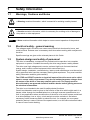
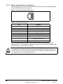
1.1
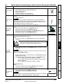
Warnings, Cautions and Notes
A Warning contains information, which is essential for avoiding a safety hazard.
WARNING
A Caution contains information, which is necessary for avoiding a risk of damage to
the product or other equipment.
CAUTION
NOTE
1.2
A Note contains information which helps to ensure correct operation of the product.
Electrical safety - general warning
The voltages used in the drive can cause severe electrical shock and/or burns, and
could be lethal. Extreme care is necessary at all times when working with or adjacent to
the drive.
Specific warnings are given at the relevant places in this Guide.
1.3
System design and safety of personnel
The drive is intended as a component for professional incorporation into complete
equipment or system. If installed incorrectly, the drive may present a safety hazard.
The drive uses high voltages and currents, carries a high level of stored electrical
energy, and is used to control equipment which can cause injury.
System design, installation, commissioning / start-up and maintenance must be carried
out by personnel who have the necessary training and experience. They must read this
safety information and this guide carefully.
The STOP and START controls or electrical inputs of the drive must not be relied
upon to ensure safety of personnel. They do not isolate dangerous voltages from
the output of the drive or from any external option unit. The supply must be
disconnected by an approved electrical isolation device before gaining access to
the electrical connections.
The drive is not intended to be used for safety-related functions.
Careful consideration must be given to the function of the drive which might result in a
hazard, either through its intended behaviour or through incorrect operation due to a
fault. In any application where a malfunction of the drive or its control system could lead
to or allow damage, loss or injury, a risk analysis must be carried out, and where
necessary, further measures taken to reduce the risk - for example, an over-speed
protection device in case of failure of the speed control, or a fail-safe mechanical brake
in case of loss of motor braking.
6
www.leroy-somer.com
Mentor MP Short Form Guide
Issue : c
1.4
Environmental limits
Access
Access must be restricted to authorized personnel only. Safety regulations which apply
at the place of use must be complied with.
1.6
Fire protection
1.7
Compliance with regulations
Within the European Union, all machinery in which this product is used must comply
with the following directives:
2006/42/EC: Safety of machinery
1.8
Motor
Ensure the motor is installed in accordance with the manufacturer's recommendations.
Ensure the motor shaft is not exposed.
The values of the motor parameters set in the drive affect the protection of the motor.
The default values in the drive should not be relied upon.
1.9
Advanced
parameters
It is essential that the correct value is entered into Pr 5.07 (SE07, 0.28), Motor rated
current. This affects the thermal protection of the motor.
SMARTCARD
operation
Low speeds may cause the motor to overheat because the cooling fan becomes less
effective. The motor should be installed with a protection thermistor. If necessary, an
electric forced ventilation fan should be used.
Running the motor
2004/108/EC: Electromagnetic compatibility
Getting started
The Mentor MP User Guide contains instructions for achieving compliance with specific
EMC standards.
Electrical
installation
The installer is responsible for complying with all relevant regulations, such as national
wiring regulations, accident prevention regulations and electromagnetic compatibility
(EMC) regulations. Particular attention must be given to the cross-sectional areas of
conductors, the selection of fuses and other protection, and protective ground (earth)
connections.
Mechanical
installation
The drive enclosure is not classified as a fire enclosure. A separate fire enclosure must
be provided.
Product information
1.5
Safety
Information
Instructions within the supplied data and information within the Mentor MP User Guide
regarding transport, storage, installation and the use of the drive must be complied with,
including the specified environmental limits. Drives must not be subjected to excessive
physical force.
Adjusting parameters
Diagnostics
Some parameters have a profound effect on the operation of the drive. They must not
be altered without careful consideration of the impact on the controlled system.
Measures must be taken to prevent unwanted changes due to error or tampering.
UL listing
Mentor MP Short Form Guide
Issue : c
7
www.leroy-somer.com
1.10
Electrical installation
1.10.1 Electric shock risk
The voltages present in the following locations can cause severe electric shock and may
be lethal:
•
•
•
AC supply cables and connections
Output cables and connections
Many internal parts of the drive, and external option units
Unless otherwise indicated, control terminals are single insulated and must not be
touched.
1.10.2 Stored charge
The drive contains capacitors that remain charged to a potentially lethal voltage after the
AC supply has been disconnected. If the drive has been energized, the AC supply must
be isolated at least ten minutes before work may continue.
8
www.leroy-somer.com
Mentor MP Short Form Guide
Issue : c
Product information
2.1
Introduction
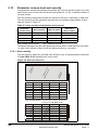
Table 2-1 Model to frame size cross reference
Product
information
The Mentor MP Short Form Guide is designed as a concise aid to drive installation and
operation. More information, including the Mentor MP User Guide and Mentor MP
Advanced User Guide, can be found on the CD supplied with the drive.
Safety Information
2
Model
575V
EN/IEC
cULus to 600V
MP25A5(R)
MP45A5(R)
MP75A4(R)
MP75A5(R)
Frame
1A
MP105A4(R)
MP105A5(R)
MP155A4(R)
MP155A5(R)
MP210A4(R)
MP210A5(R)
MP350A4(R)
MP350A5(R)
MP350A6(R)
MP470A5(R)
MP470A6(R)
MP700A4(R)
MP700A5(R)
MP700A6(R)
MP825A4(R)
MP825A5(R)
MP825A6(R)
MP1200A4
MP1200A5
MP1200A6
MP1850A4
MP1850A5
MP1850A6
MP1200A4R
MP1200A5R
MP1200A6R
MP1850A4R
MP1850A5R
MP1850A6R
Electrical
installation
MP25A4(R)
MP45A4(R)
690V
EN/IEC
Mechanical
installation
480V
EN/IEC
cULus
1B
Getting started
MP420A4(R)
2A
MP550A4(R)
Running the motor
2B
MP900A4(R)
SMARTCARD
operation
2.2
2C
2D
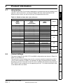
Current ratings
Advanced
parameters
The power ratings for the 480V, 575V and 690V configurations are shown in Table 2-2,
Table 2-3 and Table 2-4.
The continuous current ratings given are for a maximum ambient temperature of 40°C
(104°F) and an altitude of 1000m. For operation at higher temperatures and altitudes
de-rating is required. Overload of 150% for 30s is available with ambient temperature of
40°C (104°F) up to a maximum of 10 repetitions per hour. For further information refer
to the Mentor MP User Guide.
Diagnostics
UL listing
Mentor MP Short Form Guide
Issue : c
9
www.leroy-somer.com
Table 2-2 480V current ratings
AC input
current
Model
DC output current
Typical motor power
Continuous
Continuous
150%
overload
@
400Vdc
@
500Vdc
A
A
A
kW
hp
MP25A4(R)
22
25
37.5
9
15
MP45A4(R)
40
45
67.5
15
27
MP75A4(R)
67
75
112.5
27
45
MP105A4(R)
94
105
157.5
37.5
60
MP155A4(R)
139
155
232.5
56
90
MP210A4(R)
188
210
315
75
125
MP350A4(R)
313
350
525
125
200
MP420A4(R)
376
420
630
150
250
MP550A4(R)
492
550
825
200
300
MP700A4(R)
626
700
1050
250
400
MP825A4(R)
738
825
1237.5
300
500
MP900A4(R)
805
900
1350
340
550
MP1200A4(R)
1073
1200
1800
450
750
MP1850A4(R)
1655
1850
2775
700
1150
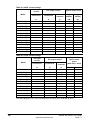
Table 2-3 575V current ratings
AC input
current
Model
Continuous
DC output current
Continuous
150%
overload
Typical motor
power
(With Vdc = 630V)
A
A
A
kW
hp
MP25A5(R)
22
25
37.5
14
18
MP45A5(R)
40
45
67.5
25
33
MP75A5(R)
67
75
112.5
42
56
MP105A5(R)
94
105
157.5
58
78
MP155A5(R)
139
155
232.5
88
115
MP210A5(R)
188
210
315
120
160
MP350A5(R)
313
350
525
195
260
MP470A5(R)
420
470*
705
265
355
MP700A5(R)
626
700
1050
395
530
MP825A5(R)
738
825*
1237.5
465
620
MP1200A5(R)
1073
1200
1800
680
910
MP1850A5(R)
1655
1850
2775
1045
1400
*For this rating at 575V, 150% overload time is 20s at 40°C and 30s at 35°C.
10
www.leroy-somer.com
Mentor MP Short Form Guide
Issue : c
AC input
current
Model
Continuous
DC output Current
Continuous
150%
Overload
Typical motor
power (With Vdc
= 760V)
A
A
kW
hp
313
350
525
240
320
MP470A6(R)
420
470*
705
320
425
MP700A6(R)
626
700
1050
480
640
738
825*
1237.5
650
850
1073
1200
1800
850
1150
MP1850A6(R)
1655
1850
2775
1300
1750
Mechanical
installation
MP825A6(R)
MP1200A6(R)
Product
information
A
MP350A6(R)
Safety Information
Table 2-4 690V current ratings
* For this rating at 690V, 150% overload time is 20s at 40°C and 30s at 35°C.
Maximum continuous input current
NOTE
Model number
The way in which the model numbers for the Mentor MP range are formed is described
in Figure 2-1.
MP 1 2 0 0 A
4
R
Running the motor
Figure 2-1 Model number
Getting started
2.3
For current ratings above 1850A then parallel connection of the drives is required.
However, this function is not implemented on firmware versions V01.05.01 and earlier.
Electrical
installation
The values of maximum continuous input current are given to aid the selection of cables
and fuses. These values are stated for worst-case condition.
SMARTCARD
operation
Mentor product line
MP : Mentor Platform
Advanced
parameters
Continuous armature current rating (A)
Voltage rating
Diagnostics
4 = 480V 24V to 480V -20% +10%
5 = 575V 500V to 575V -10% +10%
6 = 690V 500V to 690V -10% +10%
R - 4 quadrant operation
Blank - 2 quadrant operation
UL listing
Mentor MP Short Form Guide
Issue : c
11
www.leroy-somer.com
2.4
Nameplate description
Figure 2-2 Typical drive rating label
Rating
Customer and
date code
Model
Auxiliary input voltage/
frequency/current
Field output
voltage current
Line input voltage/
frequency/current
Armature output voltage/
current/overload
Approvals
Serial number
IP Rating
Key to approvals
R
2.4.1
UL approval
Worldwide
CE approval
Europe
C Tick approval
Australia
RoHS compliant
Europe
Output current
The continuous output current ratings given on the rating label are for maximum 40°C
(104°F) and 1000m altitude. Derating is required for higher ambient temperatures
>40°C (104°F) and higher altitude. For derating information, refer to the Mentor MP
User Guide on the CD supplied with the drive.
2.4.2
Input current
The input current is affected by the supply voltage, frequency and load inductance. The
input current given on the rating label is the typical input current.
12
www.leroy-somer.com
Mentor MP Short Form Guide
Issue : c
Drive features and options
Safety Information
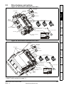
2.5
Figure 2-3 Drive features and options on size 1
SM-Keypad /
MP-Keypad
AC terminals
Identification
marker rail
Product
information
Keypad
connection
SMARTCARD*
Slot 1
Machine
feedback
terminals
Solutions Modules
Slot 2
Mechanical
installation
Slot 3
Feedback
DC
terminals
Automation
Fieldbus
Serial port connector
Electrical
installation
Control terminals
CT Comms cable
FXMP25 connection
Field fuses
FXMP25
M
Auxiliary connections
and field
Mode /Reset
STORED CHARGE
10 min
Getting started
FXMP25 Field regulator
Figure 2-4 Drive features and options on size 2
Running the motor
Identification
marker rail
SM-Keypad /
MP-Keypad
AC terminals
Keypad
connection
SMARTCARD
operation
SMARTCARD*
Slot 1
Solutions Modules
Slot 2
Slot 3
Automation
Advanced
parameters
Feedback
Fieldbus
Serial port connector
Paralleling port
Control terminals
CT Comms cable
Diagnostics
FXMP25 connection
Field fuses
FXMP25
Auxiliary connections
and field
Internal
fans
M
Mode /Reset
STO RED CHA RG E
10 min
Machine
feedback
terminals
UL listing
FXMP25 Field regulator
DC
terminals
* A SMARTCARD is provided as standard. For further information, refer to Chapter
7 SMARTCARD operation on page 74.
Mentor MP Short Form Guide
Issue : c
13
www.leroy-somer.com
2.5.1
Options available for Mentor MP
All Solutions Modules are color-coded in order to make identification easy. The following
table shows the color-code key and gives further details on their function.
Table 2-5 Solutions Module identification
Type
Solutions
Module
Color
Name
Further Details
Universal Feedback interface
Feedback interface for the following devices:
Inputs
•
Incremental
encoders
•
SinCos encoders
•
SSI encoders
•
EnDat encoders
Outputs
•
Quadrature
•
Frequency and
direction
•
SSI simulated
outputs
Light
Green
SM-Universal
Encoder Plus
Brown
SM-Encoder
Plus
Incremental encoder interface
Feedback interface for incremental encoders
without commutation signals.
No simulated encoder outputs available
Dark
Brown
SM-Encoder
Output Plus
Incremental encoder interface
Feedback interface for incremental encoders
without commutation signals.
Simulated encoder output for quadrature,
frequency and direction signals
N/A
15-way Dtype
converter
Drive encoder input converter
Provides screw terminal interface for encoder
wiring and spade terminal for shield
N/A
Single ended
encoder
interface (15V
or 24V)
Single ended encoder interface
Provides an interface for single ended ABZ
encoder signals, such as those from hall effect
sensors. 15V and 24V versions are available.
Feedback
14
www.leroy-somer.com
Mentor MP Short Form Guide
Issue : c
Type
Solutions
Module
Color
Name
Further Details
Extended I/O interface
Increases the I/O capability by adding the following
to the existing I/O in the drive:
Digital inputs x 3
•
•
•
Digital I/O x 3
Analog inputs
(voltage) x 2
•
Analog output
(voltage) x 1
Relay x 2
SM-I/O 32
Dark
Yellow
SM-I/O Lite
Additional I/O
1 x Analog input (± 10V bi-polar or current modes)
1 x Analog output (0 to 10V or current modes)
3 x Digital input and 1 x Relay
SM-I/O Timer
Additional I/O with real time clock
As per SM-I/O Lite but with the addition of a Real
Time Clock for scheduling drive running
Getting started
Turquoise SM-I/O PELV
Electrical
installation
Yellow
Extended I/O interface
Increase the I/O capability by adding the following
to the existing I/O in the drive:
•
High speed digital I/O x 32
•
+24V output
Dark Red
Isolated I/O to NAMUR NE37 specifications
For chemical industry applications
1 x Analog input (current modes)
2 x Analog outputs (current modes)
4 x Digital input / outputs, 1 x Digital input,
2 x Relay outputs
Cobalt
Blue
SM-I/O 24V
Protected
Additional I/O with overvoltage protection up to
48V
2 x Analog outputs (current modes)
4 x Digital input / outputs, 3 x Digital inputs,
2 x Relay outputs
Moss
Green
SMApplications
Plus
Applications Processor (with CTNet)
2nd processor for running pre-defined and /or
customer created application software with CTNet
support. Enhanced performance over SMApplications
White
SMApplications
Lite V2
Applications Processor
2nd processor for running pre-defined and /or
customer created application software. Enhanced
performance over SM-Applications Lite
Green
brown
SM-Register
Applications Processor
2nd processor for running position capture
functionality with CTNet support.
Diagnostics
Additional I/O conforming to IEC 61131-2
120Vac
6 digital inputs and 2 relay outputs rated for
120Vac operation
Advanced
parameters
SM-I/O 120V
SMARTCARD
operation
Olive
Running the motor
Automation
(Applications)
•
Mechanical
installation
Automation
(I/O
Expansion)
SM-I/O Plus
Product
information
Yellow
Safety Information
Table 2-5 Solutions Module identification
UL listing
Mentor MP Short Form Guide
Issue : c
15
www.leroy-somer.com
Table 2-5 Solutions Module identification
Solutions
Module
Type
Color
Name
Further Details
Purple
SMPROFIBUS
DP-V1
Profibus option
PROFIBUS DP adapter for communications with
the drive
Medium
Grey
SMDeviceNet
DeviceNet option
Devicenet adapter for communications with the
drive
Dark Grey
SMINTERBUS
Interbus option
Interbus adapter for communications with the drive
Fieldbus
Light
Grey
CANopen option
SM-CANopen CANopen adapter for communications with the
drive
Beige
SM-Ethernet
Brown
Red
EtherCAT option
SM-EtherCAT EtherCAT adapter for communications with the
drive
Ethernet option
10 base-T / 100 base-T; Supports web pages,
SMTP mail and multiple protocols: DHCP IP
addressing; Standard RJ45 connection
Table 2-6 Keypad identification
Keypad
Name
Further Details
SM-Keypad
LED keypad option
Keypad with a LED display
MP-Keypad
LCD keypad option
Keypad with an alpha-numeric LCD display with Help function
Table 2-7 Serial comms lead
Serial comms lead
Name
Further Details
CT Comms cable
CT EIA (RS) -232 (4500-0087)
CT USB (4500-0096)
Table 2-8 External field control
External field controller
Name
Further Details
FXMP25
For external control of field windings up to 25A, with field
reversal capability. For further information, please see the
FXMP25 User Guide.
FXMP25
M
Mode /Reset
STORED CHARGE
10 min
16
www.leroy-somer.com
Mentor MP Short Form Guide
Issue : c
Items supplied with the drive
The drive is supplied with a printed manual, a SMARTCARD, a safety information
booklet, the Certificate of Quality, an accessory kit box including the items shown in
Table 2-9, and a CD ROM containing all related product documentation and software
tools.
Description
Size 1
Size 2A / 2B
Size 2C / 2D
Product
information
Table 2-9 Parts supplied with the drive
Safety Information
2.6
Control connectors
Mechanical
installation
Tacho connector
Relay connectors
Electrical
installation
UL warning label
CAUTION
Risk of Electric Shock
Power down unit 10minutes
before removing cover
Getting started
UL warning label for
heatsink temperature
Grounding bracket
Running the motor
Terminal cover
grommets
SMARTCARD
operation
Terminal shrouds
Terminal shroud base
covers
M4 Screws
Advanced
parameters
Mounting feet brackets
Diagnostics
UL listing
Mentor MP Short Form Guide
Issue : c
17
www.leroy-somer.com
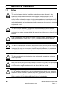
3
Mechanical installation
3.1
Safety
WARNING
WARNING
WARNING
WARNING
Follow the instructions
The mechanical and electrical installation instructions must be adhered to. Any
questions or doubt should be referred to the supplier of the equipment. It is the
responsibility of the owner or user to ensure that the installation of the drive and any
external option unit, and the way in which they are operated and maintained, comply
with the requirements of the Health and Safety at Work Act in the United Kingdom or
applicable legislation and regulations and codes of practice in the country in which the
equipment is used.
Competence of the installer
The drive must be installed by professional assemblers who are familiar with the
requirements for safety and EMC. The assembler is responsible for ensuring that the
end product or system complies with all the relevant laws in the country where it is to
be used.
If the drive has been used at high load levels for a period of time, the heatsink can
reach temperatures in excess of 70°C (158°F). Human contact with the heatsink
should be prevented.
Enclosure
The drive is intended to be mounted in an enclosure which prevents access except by
trained and authorized personnel, and which prevents the ingress of contamination. It
is designed for use in an environment classified as pollution degree 2 in accordance
with IEC 60664-1. This means that only dry, non-conducting contamination is
acceptable.
The drive enclosure is not classified as a fire enclosure. A separate fire enclosure
must be provided.
WARNING
WARNING
Many of the drives in this product range weigh in excess of 15kg (33lb). Use appropriate
safeguards when lifting these models.
A full list of drive weights can be found in the Mentor MP User Guide.
IP rating
WARNING
It is the installer’s responsibility to ensure that any enclosure which allows access to
drives from model sizes 2A to 2D while the product is energized, provides protection
against contact and ingress to the requirements of IP20.
Refer to section 12 of the Mentor MP User Guide for further details.
18
www.leroy-somer.com
Mentor MP Short Form Guide
Issue : c
WARNING
WARNING
Isolation device
The AC supply must be disconnected from the drive using an approved isolation
device before any cover is removed from the drive or before any servicing work is
performed.
Stored charge
The drive contains capacitors that remain charged to a potentially lethal voltage after
the AC supply has been disconnected. If the drive has been energized, the AC supply
must be isolated at least ten minutes before work may continue.
Mechanical
installation
3.2.1
Terminal cover removal
Safety Information Product information
3.2
Removing the terminal covers
The drive is installed with one control terminal cover.
Figure 3-1 Removing the control terminal cover (size 1 shown)
Electrical
installation
Pozi Pz2
Getting started
Running the motor
3.2.2
SMARTCARD
operation
To remove the terminal cover, undo the screw and slide the terminal cover downwards.
When replacing the terminal covers the screw should be tightened with a maximum
torque of 1 Nm (0.7 Ib ft).
Removing the finger-guard and break-outs
Advanced
parameters
Figure 3-2 Removing the finger-guard break-outs
Diagnostics
1
2
All sizes
UL listing
Mentor MP Short Form Guide
Issue : c
19
www.leroy-somer.com
Place finger-guard on a flat solid surface and hit relevant break-outs with hammer as
shown (1). Continue until all required break-outs are removed (2). Remove any flash /
sharp edges once the break-outs are removed.
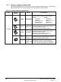
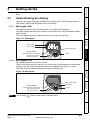
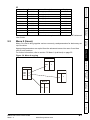
3.3
Mounting method
The Mentor MP can only be surface mounted.
Figure 3-3 Overall size 1A dimensions
1
293mm (11.54in)
250mm (9.84in)
170mm (6.69in)
222mm (8.74in)
6.5mm (0.26in)
4 holes to
suit M6
1
MA1
MA2
444mm
(17.48in)
380mm
(14.96in)
1
22mm
(0.87in)
1
40mm
(1.58in)
250mm (9.84in)
222mm
(8.74in)
95mm
(3.74in)
1. The two outer holes must be used for mounting the Mentor MP.
NOTE
With the SMARTCARD installed to the drive, the depth measurement increases by
7.6mm (0.30 in).
NOTE
Fans are only installed to the MP75A4(R) and MP75A5(R)
.
20
www.leroy-somer.com
Mentor MP Short Form Guide
Issue : c
1
1
293mm (11.54in)
250mm (9.84in)
170mm (6.69in)
6.5mm (0.26in)
4 holes to
suit M6
1
Safety Information Product information
Figure 3-4 Overall size 1B dimensions
MA1
MA2
380mm
(14.96in)
Electrical
installation
1
22mm
(0.87in)
1
Mechanical
installation
444mm
(17.48in)
40mm
(1.58in)
250mm (9.84in)
Getting started
251mm
(9.88in)
1. The two outer holes must be used for mounting the Mentor MP.
NOTE
SMARTCARD
operation
With the SMARTCARD installed to the drive, the depth measurement increases by
7.6mm (0.30 in).
Running the motor
124mm
(4.88in)
Advanced
parameters
Diagnostics
UL listing
Mentor MP Short Form Guide
Issue : c
21
www.leroy-somer.com
Figure 3-5 Installing the mounting feet bracket on size 1 drives
2
1
MA1
MA2
1
The bottom mounting bracket (1) should be installed to the back plate first with the
screws fully tightened. The drive should then be lowered onto the bracket and slotted in.
The top mounting bracket (2) should then be slotted into the drive and the top holes
marked for mounting (380mm [14.96 in] from the centre of the holes on the bottom
mounting bracket). Once the holes have been drilled, fix the top mounting bracket
accordingly and tighten the screws.
It is not necessary to tighten the bottom mounting brackets with the drive in place. The
brackets are designed to clamp the drive heatsink against the back plate
22
www.leroy-somer.com
Mentor MP Short Form Guide
Issue : c
301mm (11.85in)
453mm (17.84in)
85mm
(3.35in)
472mm (18.58)
8 holes to
suit M8
68mm
(2.68in)
80mm
(3.15in)
640mm
(25.20in)
80mm
(3.15in)
126mm
(4.96in)
11.5mm (0.45in)
93mm
(3.66in)
Mechanical
installation
65mm
(2.56in)
Safety Information Product information
Figure 3-6 Overall size 2A / 2B dimensions
495mm (19.49in)
495mm (19.49in)
Electrical
installation
302mm
(11.89in)
With the SMARTCARD installed to the drive, the depth measurement increases by
7.6mm (0.30 in).
Getting started
NOTE
Running the motor
SMARTCARD
operation
Advanced
parameters
Diagnostics
UL listing
Mentor MP Short Form Guide
Issue : c
23
www.leroy-somer.com
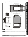
Figure 3-7 Size 2C front view and mounting dimensions
452mm (17.8in)
124mm
(4.89in)
202mm (7.95in)
390mm (15.35in)
202mm (7.95in)
605mm (23.82in)
175mm (6.9in)
175mm (6.9in)
175mm (6.9in)
6mm (0.24in)
248mm (9.76in)
321mm (12.64in)
5mm
(0.2in)
405mm (15.94)
555mm (21.85in)
24
www.leroy-somer.com
Mentor MP Short Form Guide
Issue : c
180mm (7.09in)
90mm
(3.54in)
180mm (7.09in)
Rear
90mm
(3.54in)
68.5mm
(2.70in)
83.5
(3.29in)
50mm
(1.97in)
210mm
(8.27in)
190mm
(7.48in)
240mm
(9.45in)
Safety Information Product information
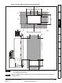
Figure 3-8 Size 2C back-plate and mounting detail
Mechanical
installation
8 holes
∅7mm
Electrical
installation
270mm
(10.63in)
Front
333mm (13.11in)
260mm
(10.24in)
394mm (15.51in)
4 holes
to suit M10
Getting started
59mm
(2.32in)
1
38mm (1.5in)
SMARTCARD
operation
53mm
(2.09in)
1050mm (41.34in)
605mm
(23.82in)
Running the motor
288mm
(11.34in)
35mm
(1.38in)
Advanced
parameters
306mm (12.05in)
611mm (24.05in)
450mm (17.72in)
1. M10 eye-bolts can be inserted in the location shown for lifting the drive. These are
not supplied with the drive.
NOTE
With the SMARTCARD installed to the drive, the depth measurement increases by
7.6mm (0.30 in).
Diagnostics
NOTE
UL listing
Mentor MP Short Form Guide
Issue : c
25
www.leroy-somer.com
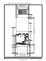
Figure 3-9 Size 2D front view and mounting dimensions
452mm (17.8in)
124mm
(4.88in)
202mm (7.95in)
390mm (15.35in)
248mm (9.76in)
1065mm (41.93in)
4mm
(0.16in)
321mm (12.64in)
356mm (14.02in)
330mm (13.0in)
330mm (13.0in)
330mm (13.0in)
6mm
(0.24in)
405mm (15.94in)
555mm (21.85in)
26
www.leroy-somer.com
Mentor MP Short Form Guide
Issue : c
180mm (7.09in)
90mm
(3.54in)
Safety Information Product information
Figure 3-10 Size 2D back-plate and mounting detail
180mm (7.09in)
90mm
(3.54in)
68.5mm
(2.70in)
83.5mm
(3.29in)
50mm
(1.97in)
190mm
(7.48in)
210mm
(8.27in)
240mm
(9.45in)
Mechanical
installation
Electrical
installation
8 holes
∅7mm
333mm (13.11in)
394mm (15.51in)
4 holes
to suit M10
Getting started
1
SMARTCARD
operation
1065mm (41.93in)
Running the motor
1510mm (59.45in)
260mm
(10.24in)
Advanced
parameters
35mm
(1.38in)
Diagnostics
288mm (11.34in)
53mm
(2.09in)
306mm (12.05in)
611mm (24.06in)
450mm (17.72in)
1. M10 eye-bolts can be inserted in the location shown for lifting the drive. These are
not supplied with the drive.
NOTE
With the SMARTCARD installed to the drive, the depth measurement increases by
7.6mm (0.30 in).
Mentor MP Short Form Guide
Issue : c
27
www.leroy-somer.com
UL listing
NOTE
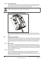
Figure 3-11 Mounting methods of size 2C / 2D air duct
The Mentor MP size 2C and 2D air duct can be turned 180° to suit the customers
infrastructure.
NOTE
3.4
There is no seal provided with this product for sealing off the gap around the air duct
when mounted.
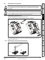
Installing and removing the terminal shrouds
Figure 3-12 Installing the terminal shrouds on size 1 drives
1
2
3
1. Thread the AC supply and DC output connectors through the grommets provided
and connect them to the drive.
28
www.leroy-somer.com
Mentor MP Short Form Guide
Issue : c
Figure 3-13 Removing the terminal shrouds on size 1 drives
1
2
Safety Information Product information
2. Place the terminal shroud over the top of the connectors and click into place (3).
Mechanical
installation
Electrical
installation
1. Insert the screwdriver as shown.
2. Lever in the direction shown to unclip the terminal shroud and remove.
1
2
Getting started
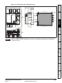
Figure 3-14 Installing the terminal shrouds on size 2 drives
3
Running the motor
L1
L2
L3
SMARTCARD
operation
Advanced
parameters
A1
A2
29
www.leroy-somer.com
UL listing
Mentor MP Short Form Guide
Issue : c
Diagnostics
1. Assemble the cable to the busbar.
2. Place the terminal shroud base cover underneath the cable in the orientation
shown.
3. Place the terminal shroud over the cable in the orientation shown, slide the terminal
shroud on to the base cover in the direction shown until it clicks in to place.
4. For all power connections slide in the terminal shroud sub-assembly in the direction
as shown.
5. Insert the 2 x M4 x 16 screws using a pozi drive screwdriver.
NOTE
3.5
To remove the terminal shrouds, please reverse the process above.
Enclosure
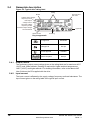
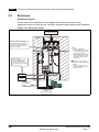
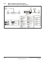
Enclosure layout
Please observe the clearances in the diagram below taking into account any
appropriate notes for other devices / auxiliary equipment when planning the installation.
Figure 3-15 Enclosure layout
AC supply contactor,
line chokes and fuses
Enclosure
A
Ensure minimum clearances
are maintained for the drive.
Forced or convection air-flow
must not be restricted by any
object or cabling
≥100mm
(4in)
≥100mm
(4in)
MA1
MA2
Signal cables
Plan for all signal cables
to be routed at least
300mm (12in) from the
drive and any power cable
Note
For EMC compliance:
1) Power cabling must be at
least 100mm (4in) from the
drive in all directions
2) Ensure direct metal contact
at drive and filter mounting
points (any paint must be
removed)
A 100mm for Size 1 drives
200mm for Size 2A/2B drives
Note
For Size 2C/2D drives
leave a clearance of 100mm
around the drive.
External
controller
A
Auxillary
supply
Armature
connection
cable
Field
connection cable
30
www.leroy-somer.com
Mentor MP Short Form Guide
Issue : c
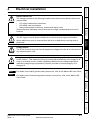
Electrical installation
Electric shock risk
The voltages present in the following locations can cause severe electric shock and
may be lethal:
WARNING
Drives are suitable for use on supplies of installation category III and lower, according
to IEC 60664-1. This means they may be connected permanently to the supply at its
origin in a building, but for outdoor installation additional over-voltage suppression
(transient voltage surge suppression) must be provided to reduce category IV to
category III.
For details on the MOV ground (earth) disconnect, refer to the Mentor MP User Guide.
NOTE
For details on the external suppressor resistor connections, refer to the Mentor MP
User Guide.
SMARTCARD
operation
NOTE
Running the motor
WARNING
STOP function
The STOP function does not remove dangerous voltages from the drive, the motor or
any external option units.
Getting started
WARNING
Isolation device
The AC supply must be disconnected from the drive using an approved isolation
device before any cover is removed from the drive or before any servicing work is
performed.
Electrical
installation
WARNING
Mechanical
installation
• AC supply cables and connections.
• DC cables, and connections.
• Many internal parts of the drive, and external option units.
Unless otherwise indicated, control terminals are single insulated and must not be
touched.
Safety Information Product information
4
Advanced
parameters
Diagnostics
UL listing
Mentor MP Short Form Guide
Issue : c
31
www.leroy-somer.com
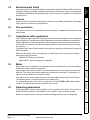
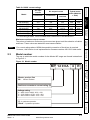
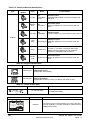
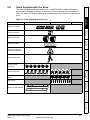
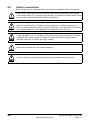
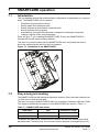
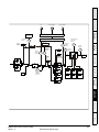
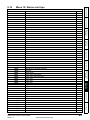
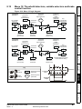
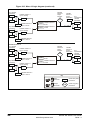
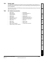
4.1
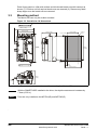
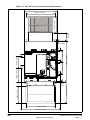
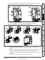
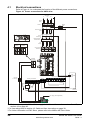
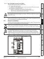
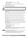
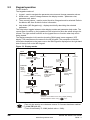
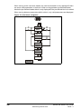
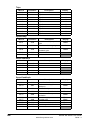
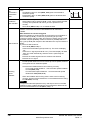
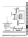
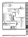
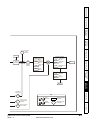
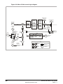
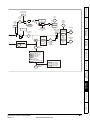
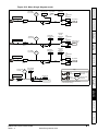
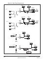
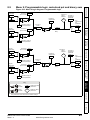
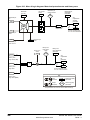
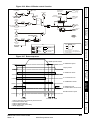
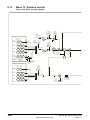
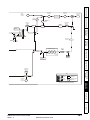
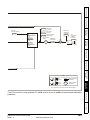
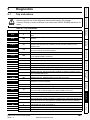
Electrical connections
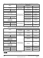
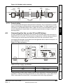
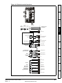
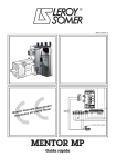
Refer to Figure 4-1 to understand the function of the different power connections.
Figure 4-1 Power connections for 480V drive
Main
AC Supply
L1
Branch
fuses
L2
*
L3
*
*
Isolator
10A
*
*
*
L1
L2
L3
10A
Semiconductor
fuses
1
Branch
fuses
Line
contactor
**Optional EMC
armature filter
Line
reactor
2 Quadrant
Drives
4 Quadrant
Drives
A2
A1
A1
A2
Input power
terminals
Armature
terminals
A1
MA1
MA2
A2
Control connections
DC fuse
for 4Q only
RLY2
Auxiliary connections
E1
E3
L12 L11
F+
F-
21 22 23 24 25 26 27 28 29 30 31
61 62 63
24V
**Optional
EMC
field
filter
Line
contactor
coil
Drive
enable
Field
on / off
250Vac
maximum
Fan supply (where applicable)
Motor
1. End user must provide 230 / 115Vac supply for the internal fans on frame sizes C and D, see
section 4.8 on page 49.
* For fuse ratings refer to section 4.6 Cable and fuse size ratings on page 38.
**For further information on EMC filters, please refer to the Mentor MP User Guide.
32
www.leroy-somer.com
Mentor MP Short Form Guide
Issue : c
Use of residual current device (RCD)
There are three common types of ELCB / RCD:
1. AC - detects AC fault currents
2. A - detects AC and pulsating DC fault currents (provided the DC current reaches
zero at least once every half cycle)
3. B - detects AC, pulsating DC and smooth DC fault currents
• Types A and AC should never be used with Mentor MP drives.
• Type B must be used with all Mentor MP drives.
WARNING
4.2
Ground connection
The drive must be connected to the system ground of the AC supply. The ground wiring
must conform to local regulations and codes of practice.
WARNING
WARNING
The ground loop impedance must conform to the requirements of local safety
regulations. The drive must be grounded by a connection capable of carrying the
prospective fault current until the protective device (fuse, etc,) disconnects the AC
supply. The ground connections must be inspected and tested at appropriate intervals.
SMARTCARD
operation
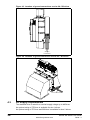
Figure 4-2 Location of ground connection on size 1 drives
Running the motor
Ground loop impedance
Getting started
Where there is a possibility of temporary condensation or corrosion occurring, the
ground connection should be protected from corrosion by suitable jointing compound.
Electrical
installation
If an external EMC filter is used, a delay of at least 50ms should be incorporated to
ensure spurious trips are not seen. The leakage current is likely to exceed the trip level
if all of the phases are not energized simultaneously.
Mechanical
installation
Only type B ELCB (Earth leakage circuit braker) / RCD are suitable for use with
Mentor MP drives.
Safety Information Product information
4.1.1
Ground
connection
Advanced
parameters
MA1
MA2
Diagnostics
UL listing
Mentor MP Short Form Guide
Issue : c
33
www.leroy-somer.com
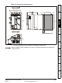
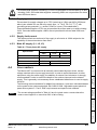
Figure 4-3 Location of ground connections on size 2A / 2B drives
Ground
connections
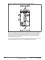
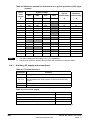
Figure 4-4 Location of ground connection on size 2C / 2D drives
Ground connection
4.3
AC supply requirements
The standard drive is rated for a nominal supply voltage up to 480Vrms.
An optional rating of 575Vrms is available for size 1 drives.
An optional rating of 575Vrms and 690Vrms is available for size 2 drives.
34
www.leroy-somer.com
Mentor MP Short Form Guide
Issue : c
4.3.1
Supply types
Drives rated for supply voltages up to 575V (rated up to 210A) and 600V (350A and
above) are suitable for use with any supply type, i.e. TN-S, TN-C-S, TT, IT, with
grounding at any potential, i.e. neutral, centre or corner ("Grounded-delta").
4.3.2
Supply fault current
The maximum fault current level of the supply to all circuits is 100kA subject to the
capability of the semiconductor fuse fitted.
Main AC supply (L1, L2, L3)
Electrical
installation
4.3.3
Table 4-1 Three phase AC supply
Specification
Product voltage variant
480V
575V
690V
480V
575V
690V
Tolerance
+10%
Minimum nominal supply
24V
500V
Tolerance
-20%
-10%
Line reactors
NOTE
The current ratings specified in Table 4-2 are for typical motor currents where the
motor current ripple is no more than 50% of drive rating.
Advanced
parameters
The following recommendations for added line inductance, have been calculated based
on the power drive systems standard: EN 61800-3:2004 “Adjustable speed electrical
power drive systems – Part 3: EMC requirements and specific test methods”.
SMARTCARD
operation
The Mentor MP, in common with all naturally commutated thyristor drives, causes
voltage notches at the input supply terminals. In order to avoid disturbance to other
equipment using the same supply, the addition of external line inductance is strongly
recommended in order to restrict the depth of the notches imposed on the shared
supply. This is generally not necessary where a dedicated transformer is used to supply
the drive.
Running the motor
4.4
Getting started
Maximum nominal supply
Mechanical
installation
Grounded delta supplies >575V are not permitted for drives rated up to and including
210A. Grounded delta supplies >600V are not permitted for drives rated 350A and
above.
Safety Information Product information
WARNING
Grounded delta supplies exceeding 575V are not permitted for drives rated up to and
including 210A. Grounded delta supplies exceeding 600V are not permitted for drives
rated 350A and above.
Diagnostics
UL listing
Mentor MP Short Form Guide
Issue : c
35
www.leroy-somer.com
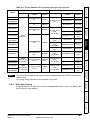
Table 4-2 Minimum required line inductance for a typical application (50% ripple
content)
Drive
rated
current
System voltage
400V
480V
575V
690V
μH
A
μH
μH
μH
A
A
220
260
320
21
22
45
220
260
320
38
40
75
220
260
320
63
67
105
220
260
320
88
94
155
160
190
230
130
139
210
120
140
170
176
188
350
71
85
110
120
293
313
420
59
71
351
375
80
91
393
420
460
492
53
61
586
626
45
52
690
738
550
45
54
700
36
43
900
28
33
1200
21
25
31
1850
18
23
29
825
4.4.1
Maximum
current rating
25
470
NOTE
Typical
current rating
753
805
36
1004
1073
32
1548
1655
1. The above assumes the supply has 1.5% impedance.
2. Assumes a minimum supply rating of 5kA and a maximum rating of 60kA.
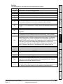
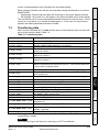
Auxiliary AC supply and connections
Table 4-3 Terminal functions
Terminals
E1, E3
L11, L12
F+, FMA1, MA2
Function
Supply for control electronics and field controller.
Field on / off. When L11 and L12 are open the supply is
disconnected to the field regulator so there will be no field
current.
Field supply to the motor.
Refer to the Mentor MP User Guide
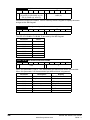
Table 4-4 Line to line supply
Specification
Value
Maximum nominal supply
480V
Tolerance
+10%
Minimum nominal supply
208V
Tolerance
-10%
Each drive has an onboard field controller with the following current ratings.
36
www.leroy-somer.com
Mentor MP Short Form Guide
Issue : c
Model
MP25A4(R)
MP25A5(R)
MP45A4(R)
MP45A5(R)
MP75A5(R)
MP105A4(R)
MP105A5(R)
MP155A4(R)
MP155A5(R)
MP210A4(R)
MP210A5(R)
MP350A4(R)
MP350A5(R)
MP350A6(R)
MP470A5(R)
MP470A6(R)
Maximum
continuous field
current rating
A
13
8
23
20
Mechanical
installation
MP75A4(R)
Maximum
auxiliary supply
input current
A
Safety Information Product information
Table 4-5 Current ratings
MP420A4(R)
MP550A4(R)
MP700A5(R)
MP700A6(R)
MP825A4(R)
MP825A5(R)
MP825A6(R)
Electrical
installation
MP700A4(R)
MP900A4(R)
MP1200A5
MP1200A6
MP1850A4
MP1850A5
MP1850A6
MP1200A4R
MP1200A5R
MP1200A6R
MP1850A4R
MP1850A5R
MP1850A6R
Getting started
4.4.2
MP1200A4
Supply requirements
Frequency range: 48 to 65 Hz (maximum rate of frequency change is 7Hz/s)
4.5
Control 24Vdc supply
•
Mentor MP Short Form Guide
Issue : c
UL listing
The working voltage range of the 24V power supply is as follows:
Maximum continuous operating voltage:
30.0V
Minimum continuous operating voltage:
19.2V
Nominal operating voltage:
24.0V
37
www.leroy-somer.com
Diagnostics
•
Advanced
parameters
•
It can be used to supplement the drive's own internal 24V when multiple SMUniversal Encoder Plus, SM-Encoder Output Plus, SM-I/O Plus, or SM-I/O 32
modules are being used and the current drawn by these modules is greater than the
drive can supply. (If too much current is drawn from the drive, the drive will initiate a
'PS.24V' trip)
It can be used as a back-up power supply to keep the control circuits of the drive
powered up when the line power supply is removed. This allows any fieldbus
modules, application modules, encoders or serial communications to continue to
operate.
It can be used to commission the drive when the line power supply is not available,
as the display operates correctly. However, the drive will be in the UV trip state
unless the line power supply is enabled, therefore diagnostics may not be possible
(Power down save parameters are not saved when using the 24V back-up power
supply input).
SMARTCARD
operation
The 24Vdc input has three main functions.
Running the motor
Maximum supply in-balance: 2% negative phase sequence (equivalent to 3% voltage inbalance between phases)
Minimum start up voltage:
Maximum power supply requirement at 24V:
Recommended fuse:
21.6V
60W
3 A, 50Vdc
Minimum and maximum voltage values include ripple and noise. Ripple and noise
values must not exceed 5%.
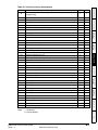
4.6
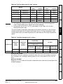
Cable and fuse size ratings
The selection of the correct fuse is essential to ensure the safety of the installation
WARNING
Maximum continuous input currents are given in section 2.2 Current ratings on page 9
to aid the selection of fuses and cabling. The maximum input current is dependent on
the ripple content of the output current. A value of 100% ripple has been assumed for
the given ratings.
The cable sizing selected when installing a Mentor MP must comply with the local wiring
regulations. The information provided in this section is provided for guidance purposes
only.
The power terminals on Mentor MP frame size 1 drives have been designed to
accommodate a maximum cable size of 150mm2 (350kcmil) with a temperature of 90°C
(194°F).
The power terminals on Mentor MP frame size 2A drives have been designed to
accommodate a maximum cable size of 2 x 150mm2 (2 x 350kcmil) with a temperature
of 75°C (167°F).
The power terminals on Mentor MP frame size 2B drives have been designed to
accommodate 2 x 240mm2 with a temperature of 90°C (194°F). The use of cables sized
using the US national electrical code as shown in Table 4-8 requires the use of a
terminal adaptor.
The power terminals on Mentor MP frame size 2C and 2D drives have been designed
for use with busbars. The drive can be used with cables as shown in Table 4-8 with the
use of a terminal adaptor.
The actual cable size depends on a number of factors including:
•
•
•
•
Actual maximum continuous current
Ambient temperature
Cable support, method and grouping
Cable voltage drop
In applications where the motor used is of a reduced rating, the cable sizing selected
can be appropriate for that motor. To protect the motor and the output cabling the drive
must be programmed with the correct motor rated current.
NOTE
When using reduced cable sizes, the branch circuit protection fuse rating needs to be
reduced in line with the cable size selected.
The following table shows typical cable sizes based on USA and International
standards, assuming 3 conductors per raceway/conduit, an ambient temperature of
40°C (104°F) and applications with high output current ripple content.
38
www.leroy-somer.com
Mentor MP Short Form Guide
Issue : c
IEC 60364-5-52[1]
Model
Input
Output
Input
Output
4mm2
8 AWG
8 AWG
MP25A5(R)
MP45A4(R)
MP45A5(R)
10mm2
10mm2
4 AWG
4 AWG
MP75A4(R)
MP75A5(R)
16mm2
25mm2
1 AWG
1/0 AWG
MP105A4(R)
MP105A5(R)
25mm2
35mm2
1/0 AWG
1/0 AWG
MP155A4(R)
MP155A5(R)
50mm2
70mm2
3/0 AWG
4/0 AWG
MP210A5(R)
95mm2
95mm2
300kcmil
350kcmil
Mechanical
installation
MP25A4(R)
2.5mm2
MP210A4(R)
NOTE
UL508C/NEC[2]
The use of higher temperature rated cable would allow a reduction on the minimum
recommended cable size for Mentor MP shown above. For high temperature cable
sizing, please refer to the data supplied by the manufacturer of the high temperature
cable.
Getting started
Table 4-7 Auxiliary wiring for size 1 drives
IEC 60364-5-52 Table A52-4
Column B2
E1, E3 size
F+, F- , L11 &
L12 size
E1, E3 size
F+, F- , L11
& L12 size
A
A
mm²
mm²
mm²
mm²
13
8
2.5
1.5
14 AWG
14 AWG
Notes for UL508C:
Either 60°C or 75°C cable can be used. Ampacities as per table 40.3 as described in the
UL508C standard.
Advanced
parameters
Notes for IEC 60364:
IEC 60364-5-52 use installation method B2, table A.52-4 for three loaded conductors,
PVC insulation 30°C and apply derating factor for 40°C from table A.52-14 (0.87 for
PVC).
SMARTCARD
operation
1
UL 508C
Column B2 derated by 0,87
of PVC at 40
Running the motor
Frame size
Continuous
output
current
Electrical
installation
1. The maximum cable size is defined by the power terminal housing using 90°C
(194°F) rated cables as per Table A.52-5 of the standard.
2. Assumes the use of 75°C (167°F) rated cables, as per Table 310.16 of the
National Electrical Code.
Maximum
input
current
Safety Information Product information
Table 4-6 Typical cable sizes for size 1 drives
Diagnostics
UL listing
Mentor MP Short Form Guide
Issue : c
39
www.leroy-somer.com
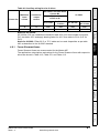
Table 4-8 Typical cable sizes for size 2 drives
IEC 60364-5-52
Table A52-12
Column 5 derated
by 0.91 for 40°C
XLPE cables (IEC
Maximum Continuous 60364-5-52 table
input
output
A52-14) and 0.77 for
current
current
cables bunching
(IEC 60364-5-52
table A52-17 item 4)
Model
US National
Electrical Code
90°C cables at 40°C 75°C cable at 40°C
ambient
ambient
Input
size
mm²
Output
size
mm²
Input
cables
Kcmil
Output
cables
Kcmil
350
120
150
350
400
420
150
185
400
500
420
470
185
240
500
600
MP550A4(R)
492
550
300
2 x 185
2 x 300
2 x 350
MP700A4(R) MP700A5(R) MP700A6(R)
626
700
2 x 150
2 x 150
2 x 500
2 x 600
MP825A4(R) MP825A5(R) MP825A6(R)
738
825
2 x 185
2 x 240
2 x 600
3 x 350
MP900A4(R)
805
900
2 x 185
2 x 240
3 x 350
3 x 400
MP1200A4(R) MP1200A5(R) MP1200A6(R)
1073
1200
2 x 300
3 x 240
3 x 600
4 x 400
MP1850A4(R) MP1850A5(R) MP1850A6(R)
1655
1850
4 x 240
4 x 300
*
*
A
A
MP350A4(R) MP350A5(R) MP350A6(R)
313
MP420A4(R)
375
MP470A5(R) MP470A6(R)
* Values are beyond the mechanical design of the drive. At this power level it may be
prudent to consider busbars.
Notes for IEC 60364:
NOTE
1. IEC 60364-5-52 table A 52-12 F method column 5 = Single core cable in free air.
2. IEC 60364-5-52 table A52-14 correction factor for ambient air temperature others
than 30°C.
3. IEC 60364-5-52 table A52-17 item 4 correction factor for groups of more than one
circuit or more than one multi-core cable placed on a single layer on a perforated
tray.
Notes for US National Electrical Code:
NOTE
1. Table 310.17 allowable ampacities of single-insulated conducted rated 0 through
2000V in free air, based on ambient air temperature of 30°C (87°F).
2. Derating factor of 0.88 is applied for 40°C to the 75°C cable column. Table 310.17
is based on 30°C (86°F) ambient air temperature.
3. NEC 2005 edition table 310.15(B)(2)(a) shows the adjustment factors for more
than three current-carrying conductors in a race way or cable, for 4-6 currentcarrying conductors 0.80 derating factor is applied.
40
www.leroy-somer.com
Mentor MP Short Form Guide
Issue : c
IEC 60364-5-52 Table A52-4
Column B2
Frame size
2
Maximum
input
current
Continuous
output
current
UL 508C
Column B2 derated by 0,87
of PVC at 40
E1, E3 size
F+, F- , L11 &
L12 size
E1, E3 size
F+, F- , L11
& L12 size
A
A
mm²
mm²
mm²
mm²
23
20
6
4
10 AWG
10 AWG
4.6.1
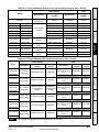
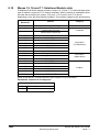
Ferraz Shawmut fuses
Ferraz Shawmut fuses are recommended for the Mentor MP.
Getting started
The applications, descriptions and ratings for the Ferraz Shawmut fuses with respect to
drives are shown in Table 4-10, Table 4-11 and Table 4-12.
Electrical
installation
Notes for UL508C: Either 60°C or 75°C cable can be used. Ampacities as per table
40.3 as described in the UL508C standard.
Mechanical
installation
Notes for IEC 60364:
IEC 60364-5-52 use installation method B2, table A.52-4 for three loaded conductors,
PVC insulation 30°C and apply derating factor for 40°C from table A.52-14 (0.87 for
PVC).
Safety Information Product information
Table 4-9 Auxiliary wiring for size 2 drives
Running the motor
SMARTCARD
operation
Advanced
parameters
Diagnostics
UL listing
Mentor MP Short Form Guide
Issue : c
41
www.leroy-somer.com
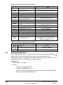
Table 4-10 Ferraz Shawmut semiconductor fusing for size 1 drives
International
Model
Field fuses
Description
Catalogue
number
Ref
number
Description
Catalogue
number
Ref
number
10 x 38mm
Ferrule
FR10GB69V1
2.5
H330011
10 x 38mm Ferrule
FR10GB69V1
2.5
H330011
FR22GC69V3
2
A220915
A50QS Series
American Round Fuse
A50QS60-4
A218937
FR22GC69V6
3
X220912
A50QS Series
American Round Fuse
A50QS80-4
L201513
FR22GC69V1
00
W220911
A50QS Series
A50QS125-4
American Round Fuse
K218417
FR22GC69V3
2
A220915
A70QS Series
American Round Fuse
A70QS60-4
H219473
FR22GC69V6
3
X220912
A70QS Series
American Round Fuse
A70QS80-4
X212816
FR22GC69V1
00
W220911
A70QS Series
A70QS125-4
American Round Fuse
Q216375
PC30UD69V1
60EF
M300092
A50QS Series
A50QS175-4
American Round Fuse
A222663
PC30UD69V2
00EF
N300093
A50QS Series
A50QS250-4
American Round Fuse
W211251
PC30UD69V3
15EF
Q300095
A50QS Series
A50QS350-4
American Round Fuse
T215343
PC70UD13C1
60EF
T300604
A70QS Series
A70QS175-4
American Round Fuse
A223192
PC70UD13C2
00EF
V300605
A70QS Series
A70QS250-4
American Round Fuse
L217406
PC70UD12C2
80EF
L300712
A70QS Series
A70QS350-4
American Round Fuse
M211266
MP25A4
MP25A5
MP45A4
MP45A5
MP75A4
MP75A5
MP25A4R
22 x 58mm
Ferrule
MP25A5R
MP45A4R
MP45A5R
MP75A4R
MP75A5R
MP105A4
MP105A5
MP155A4
MP155A5
Size 30
Square Body
Fuse
MP210A4
MP210A5
MP105A4R
MP105A5R
MP155A4R
MP155A5R
MP210A4R
MP210A5R
NOTE
USA
Size 70
Square Body
Fuse
A50QS series are only rated up to 500Vac.
42
www.leroy-somer.com
Mentor MP Short Form Guide
Issue : c
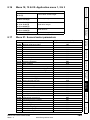
International
Model
Auxiliary
USA
Catalogue
number
Ref number
Catalogue
number
21 x 57mm
Cylindrical
HSJ15
D235868
AJT10
N212072
P214626
Q217180
N212072
P214626
Q217180
AJT30
AJT45
AJT70
AJT30
AJT45
AJT70
22 x 58mm
Ferrule
FR22GG69V25
FR22GG69V50
FR22GG69V80
FR22GG69V25
FR22GG69V50
FR22GG69V80
MP105A4
MP105A5
NH 00 Knife
Blade
NH00GG69V100
B228460
AJT125
MP155A4
MP210A4
MP155A5
MP210A5
NH 1 Knife
Blade
NH1GG69V160
NH1GG69V200
F228487
G228488
AJT175
AJT225
MP105A4R
MP105A5R
NH 00 Knife
Blade
NH00GG69V100
B228460
AJT125
MP155A4R
MP210A4R
MP155A5R
MP210A5R
NH 1 Knife
Blade
NH1GG69V160
NH1GG69V200
F228487
G228488
AJT175
AJT225
Getting started
MP25A5
MP45A5
MP75A5
MP25A5R
MP45A5R
MP75A5R
Electrical
installation
MP25A4
MP45A4
MP75A4
MP25A4R
MP45A4R
MP75A4R
Mechanical
installation
Description
Table 4-12 Ferraz Shawmut DC protection fusing for size 1 drives
International
Model
Description
MP25A4R
USA
Ref
number
Catalogue
number
Ref
number
A70QS60-4
H219473
X212816
FD20GB100V32T
F089498
A70QS Series
American Round
Fuse
36 x 127mm
Cylindrical
FD36GC100V80T
A083651
A70QS Series
American Round
Fuse
A70QS80-4
A70QS Series
American Round
Fuse
A70QS125-4 Q216375
A70QS175-4 A223192
MP25A5R
MP45A4R
MP45A5R
MP75A4R
MP75A5R
MP105A4R
20 x 127mm
Cylindrical
FD20GC100V63T x F083656 x 2
2 connected in
connected in
parallel.
parallel.
Size 120
D120GC75V160TF
Square Body
R085253
A70QS Series
American Round
Fuse
Size 121
D121GC75V250TF
Square Body
Q085252
A70QS Series
American Round
Fuse
A70QS250-4
Size 122
D122GC75V315TF
Square Body
M085249
A70QS Series
American Round
Fuse
A70QS350-4 M211266
Advanced
parameters
20 x 127mm
Cylindrical
SMARTCARD
operation
Description
Running the motor
Catalogue
number
Safety Information Product information
Table 4-11 Ferraz Shawmut branch circuit protection fusing for size 1 drives
MP105A5R
L217406
MP155A5R
MP210A4R
UL listing
MP210A5R
NOTE
DC fusing is required on four quadrant (R) drives only.
Mentor MP Short Form Guide
Issue : c
43
www.leroy-somer.com
Diagnostics
MP155A4R
Table 4-13 Ferraz Shawmut semiconductor fusing for International size 2 drives
Model
Field fuses
MP350A4
MP350A4R
MP350A5
MP350A6
MP350A5R
MP350A6R
MP420A4
MP420A4R
MP470A5
MP470A6
MP470A5R
MP470A6R
MP550A4
MP550A4R
MP700A4
MP700A4R
MP700A5
MP700A6
MP700A5R
MP700A6R
MP825A4
MP825A5
MP825A6
MP825A4R
MP825A5R
MP825A6R
MP900A4
MP900A4R
MP1200A4
MP1200A4R
MP1200A5
MP1200A6
MP1200A5R
MP1200A6R
MP1850A4
MP1850A4R
MP1850A5
MP1850A6
MP1850A5R
MP1850A6R
NOTE
International
Description
Catalogue number
Ref number
10 x 38mm Ferrule
FR10GB69V25
PC30UD69V500TF
PC71UD11V500TF
L330014
W300399
F300523
PC31UD69V500TF
T300006
PC72UD13C500TF
D300498
PC32UD69V630TF
PC272UD13C630TF
M300069
W300721
PC272UD13C700TF
X300722
PC33UD69V700TF
PC272UD13C700TF
PC32UD69V1000TF
PC72UD10C900TF
Y300079
X300722
S300074
G300869
PC32UD69V1000TF
S300074
PC73UD12C900TF
T300512
PC32UD69V1100TF
M300759
PC33UD69V1100TF
C300083
PC73UD95V800TFB
W300514
PC33UD69V1250TF
PC73UD95V800TFB
PC33UD60V1600TF
PC273UD11C16CTF
D300084
W300514
Z300586
J302228
PC232UD69V16CTD
W300215
PC273UD11C16CTF
J302228
**7,5 URD 44 PPSAF 2200
**K235184
Square
Body Fuses
A50QS series are only rated up to 500Vac.
*Application overload limited to infrequent overloads to avoid fuse wear out
**Fuse limits applications to those operating at rated current. No cyclic overloads permitted.
44
www.leroy-somer.com
Mentor MP Short Form Guide
Issue : c
Model
Field fuses
USA
Description
Catalogue number
Ref number
10 x 38mm Ferrule
FR10GB69V25
MP350A4R
MP350A5
MP350A6
MP350A5R
MP350A6R
A7OQS450-4
L330014
EQ16871
F214848
F214848
A70QS450
F214848
MP420A4
A50QS600-4 A70QS600-4
MP420A4R
MP470A5
MP470A6
MP470A5R
MP470A6R
A70QS600-4
Q219457
Y219993
Y219993
2 x A70QS400 in parallel
J214345 (x2)
A218431 (x2)
A50QS1200-4
2 x A70QS600-4 in parallel
C217904
Y219993 (x2)
2 x A7OQS600-4 in parallel
Y219993 (x2)
A50QS1200-4
2 x A7OQS600-4 in parallel
2 x A7OQS600-4 in parallel
2 x A5OQS800-4 in parallel
2 x A70QS800-4 in parallel
C217904
Y219993 (x2)
Y219993 (x2)
C202287 (x2)
Z213830 (x2)
MP1200A4R
MP1200A5
MP1200A6
MP1200A5R
MP1200A6R
2 x A70QS800-4
in parallel
Z213830 (x2)
MP1850A4
2 x A5OQS1000-4 in parallel
*3 x A7OQS700-4 in parallel
B217391 (x2)
*E202772 (x3)
MP1850A4R
MP1850A5
MP1850A6
MP1850A5R
MP1850A6R
*3 x A7OQS700-4
in parallel
*E202772 (x3)
MP825A4
MP825A5
MP825A6
MP825A4R
MP825A5R
MP825A6R
MP900A4
MP900A4R
MP1200A4
A50QS series are only rated up to 500Vac.
*Application overload limited to infrequent overloads to avoid fuse wear out
**Fuse limits applications to those operating at rated current. No cyclic overloads permitted.
Mentor MP Short Form Guide
Issue : c
45
www.leroy-somer.com
UL listing
NOTE
Diagnostics
2 x A70QS500 in parallel
American
Round Fuses
Form 101
Range A70QS
Advanced
parameters
A70QS700-4
A50QS900-4
2 x A70QS500-4 in parallel
MP700A4
SMARTCARD
operation
MP550A4R
N223181
E202772
E202772
R212282
A218431 (x2)
Running the motor
A50QS700-4 A70QS700-4
Getting started
MP550A4
Electrical
installation
A50QS450-4 A7OQS450-4
Mechanical
installation
MP350A4
MP700A4R
MP700A5
MP700A6
MP700A5R
MP700A6R
Safety Information Product information
Table 4-14 Ferraz Shawmut semiconductor fusing for USA size 2 drives
Table 4-15 Ferraz Shawmut branch circuit protection fusing for International size 2 drives
Model
Auxiliary
International
Description
Catalogue number
Ref number
25A 600Vac High
Speed Class J
HSJ205
G235871J
NH2GG69V355
Y228503
NH3GG69V400
NH4GG69V630-8
NH4AGG69V630-8
NH4GG69V630-8
NH4AGG69V630-8
NH4GG69V800-8
NH4AGG69V800-8
D228508
E215537
W222107
E215537
W222107
K216554
M222858
NH4GG69V800-8
NH4AGG69V800-8
K216554
M222858
MF76GG69V1250
E302753
MF114GG69V2000
G302755
MP350A5(R)
MP350A6(R)
MP420A4(R)
MP470A5(R)
MP470A6(R)
MP350A4(R)
MP550A4 (R)
MP700A5(R)
MP700A6(R)
MP825A4(R)
MP825A5(R)
MP825A6(R)
MP900A4R)
MP1200A5(R)
MP1200A4(R)
MP1200A6(R)
MP1850A5(R)
MP1850A4(R)
MP1850A6(R)
General purpose
IEC (square body)
MP700A4(R)
General purpose
IEC (round body)
Table 4-16 Ferraz Shawmut branch circuit protection fusing for USA size 2 drives
USA
Model
Auxiliary
MP350A5(R)
MP350A6(R)
MP420A4(R)
MP470A5(R)
MP470A6(R)
MP550A4 (R)
MP700A5(R)
MP700A4(R)
MP700A6(R)
MP825A4(R)
MP825A5(R)
MP825A6(R)
MP900A4R)
MP1200A5(R)
MP1200A4(R)
MP1200A6(R)
MP1850A5(R)
MP1850A4(R)
MP1850A6(R)
Description
Catalogue
number
Ref
number
25A 600Vac
High Speed
Class J
AJT25R
X21160J
A6D400R
B216776
A6D500R
P217294
A6D600R
T217804
A4BQ800
Z219373
A4BQ1000
P216282
A4BQ1200
R216790
A4BQ2000
B223101
MP350A4(R)
NOTE
General purpose
US (round body)
USA fuses are only rated up to 600Vac.
46
www.leroy-somer.com
Mentor MP Short Form Guide
Issue : c
International
Model
Ref
number
D123GB75V630
TF
C098557
D123GB75V800
TF
J220946
Description
MP350A4R
MP350A5R
MP350A6R
MP420A4R
MP470A5R
MP470A6R
MP700A4R
T220955
D098558
A100P600-4
A217373
A70QS800-4
Z213830
A100P1000-4 (x2)
Y217371
(x2)
A70QS450-4 (x2)
F214848
(x2)
A70QS600-4 (x2)
Y219993
(x2)
American round
fuse
A100P1200-4
N218397
American round
fuses
2 in parallel
A70QS800-4 (x2)
Z213830
(x2)
American round
fuse
A100P1200-4
N218397
A70QS600-4 (x3)
Y219993
(x3)
American round
fuses
2 in parallel
B090483
American round
fuses
3 in parallel
Square
Body fuses
3 in parallel
PC73UD13C630
TF (x3)
Q300509
(x3)
American round
fuses
3 in parallel
A70QS700-4 (x3)
E202772
(x3)
A100P700-4 (x3)
T223163
(x3)
Square
Body fuses
4 in parallel
PC73UD13C700
TF (x4)
R300510
(x4)
American round
fuses
5 in parallel
A70QS600-4 (x5)
Y219993
(x5)
A100P600-4 (x5)
A217373
(x5)
The use of the A100P series fuses is limited to applications with L/R time constants of
30ms or less.
SMARTCARD
operation
NOTE
Y219993
Running the motor
MP1850A5R
MP1850A6R
A70QS600-4
D2123GB75V14
CTF
MP900A4R
MP1850A4R
Ref
number
Getting started
MP825A5R
MP825A6R
Catalogue
number
Electrical
installation
D2123GB75V12
CTF
MP825A4R
MP1200A5R
MP1200A6R
American round
fuse
Square
Body fuse
MP700A5R
MP700A6R
MP1200A4R
Description
Mechanical
installation
D2122GD75V90
0TF
MP550A4R
USA
Catalogue
number
Safety Information Product information
Table 4-17 Ferraz Shawmut DC protection fusing for size 2 drives
DC fusing is only required on four quadrant (R) drives.
Alternative fusing
Cooper Bussmann or Siba fuses are an acceptable alternative (refer to the Mentor MP
User Guide for more details).
Advanced
parameters
4.6.2
Diagnostics
UL listing
Mentor MP Short Form Guide
Issue : c
47
www.leroy-somer.com
4.6.3
Internal field fuses
The internal field fuses provide protection to the field controller. The fuses can rupture if
there is a fault in the field circuit. The user should check the internal field fuses if the
drive is tripping field loss (FdL) and the field controller is enabled.
Isolate the power before removing the internal field fuses.
WARNING
Figure 4-5 Removing the internal field fuses
Insert a flat-head screwdriver into the groove as shown above and lever downwards to
remove the fuse cover. Refer to section 4.6.1 Ferraz Shawmut fuses on page 41 for fuse
types.
4.7
Shield connections
These instructions must be followed to ensure suppression of radio-frequency emission
and good noise immunity in the encoder circuit. It is recommended that the instructions
for the connection of the encoder cable be followed closely and, to use the grounding
bracket and grounding clamp supplied with the drive, to terminate the shields at the
drive.
4.7.1
Motor cables
Use of a motor cable with an overall shield for the armature and field circuits may be
needed if there is a critical EMC emissions requirement. Connect the shield of the motor
cable to the ground terminal of the motor frame using a link that is as short as possible
and not exceeding 50mm (2in) long. A full 360° termination of the shield to the terminal
housing of the motor is beneficial.
4.7.2
Encoder cable
To get the best results from shielding use cable with an overall shield and separate
shields on individual twisted pairs. Connect the cable as illustrated in Figure 4-6.
Assemble and clamp the overall shield to the grounded metallic surfaces at the encoder
and at the drive ends of the cable.
48
www.leroy-somer.com
Mentor MP Short Form Guide
Issue : c
Shield
connection
to 0V
Twisted
pair
shield
Cable
Twisted
pair
shield
Shield
connection
to 0V
Connection
at drive
Connection
at motor
Cable
shield
Cable
shield
.
4.7.3
Control cables
4.8
Electrical
installation
It is recommended that signal cables should be shielded. This is essential for encoder
cables, and strongly recommended for analog signal cables. For digital signals it is not
necessary to use shielded cables within a panel, but this is recommended for external
circuits, especially for inputs where a momentary signal causes a change of state (i.e.
latching inputs).
Mechanical
installation
Ground clamp
on shield
Safety Information Product information
Figure 4-6 Shielded cable assembly
Connecting the fan on size 2C and 2D drives
Getting started
A supply needs to be connected to the dual fan unit enclosed within the lower duct on
Mentor MP size 2C and 2D. The fans can be configured for a 230Vac (factory setting) or
115Vac supply as shown below on the label next to the fan connections. When
connecting the fan supply, the screws should be tightened with a maximum torque of 1.2
Nm (0.88 Ib ft) to 2 Nm (1.47 Ib ft).
Running the motor
Figure 4-7 Fan connection
SMARTCARD
operation
Advanced
parameters
Fan configuration
Supply specification
230V
230V ±10%
115V
115V ±10%
Diagnostics
Table 4-18 Fan supply specification
Mentor MP Short Form Guide
Issue : c
49
www.leroy-somer.com
UL listing
Cabling should be 300V rated. Rated for at least 3A continuous in line with local wiring
regulations. Cabling should be protected 3A non time delay fuses i.e. gG, Class CC or
Class J and rated for at least 300V, in accordance with local wiring regulations.
4.9
Control connections
Refer to Figure 4-8 to understand the connection of the different power connections.
WARNING
CAUTION
WARNING
If the control circuits are to be connected to other circuits classified as Safety Extra
Low Voltage (SELV) (e.g. to a personal computer), an additional isolating barrier must
be included in order to maintain the SELV classification.
If any of the digital inputs (including the drive enable input) are connected in parallel
with an inductive load (i.e. contactor or motor brake) then suitable suppression (i.e.
diode or varistor) should be used on the coil of the load. If no suppression is used then
over voltage spikes can cause damage to the digital inputs on the drive.
The control circuits are isolated from the power circuits in the drive by basic insulation
(single insulation) only. The installer must ensure that the external control circuits are
insulated from human contact by at least one layer of insulation (supplementary
insulation) rated for use at the AC supply voltage
Status relay contacts are over-voltage category II.
WARNING
A fuse or other over-current protection should be installed to the relay circuit.
WARNING
For the full terminal descriptions, refer to the Mentor MP User Guide.
50
www.leroy-somer.com
Mentor MP Short Form Guide
Issue : c
Safety Information Product information
Figure 4-8 Default terminal functions
MA1
MA2
Mechanical
installation
Encoder
Status
relay 1
Status
relay 2
51 52 53 61 62 63
A A\ B B\ 1
11
Tacho
Arm
41 42 current
Polarized signal
connectors
Z Z\ + 0
21
Electrical
installation
+ _
31
1
0V
2
+24V input
3
0V
5
Non-inverting input
6
Inverting input
Analog speed reference 1
Getting started
Single-ended
signal
0V
Non-inverting input
Inverting input
Analog speed
reference 2
Speed
Armature
current
4
+10V output
7
Analog input 2
8
Analog input 3*
9
Analog output 1
10
Analog output 2
11
0V
0V
22
+24V output
0V
24
Digital I/O 1
Reset
25
Digital I/O 2
Run forward
26
Digital I/O 3
27
Digital input 4
28
Digital input 5
29
Digital input 6
Diagnostics
23
At speed
Advanced
parameters
21
SMARTCARD
operation
Analog input 3
(Motor thermistor)
Run reverse
Analog input 1/
input 2 select
Running the motor
Differential signal
Analog input 1
Analog input 2
Jog forward select
0V
31
Drive enable
UL listing
30
* Thermistor disabled by USA defaults.
Mentor MP Short Form Guide
Issue : c
51
www.leroy-somer.com
4.9.1
Serial communications connections
The Mentor MP has a serial communications port (serial port) as standard supporting
two wire EIA(RS)-485 communications.
Figure 4-9 Serial communications port
1
8
Table 4-19 RJ45 connections
Pin
Function
1
120Ω Termination resistor
2
RX TX
3
0V isolated
4
+24V (100 mA)
5
0V isolated
6
TX enable
7
RX\ TX\
8
RX\ TX\ (if termination resistors are
required, link to pin 1)
Shell
0V isolated
The communications port applies a two-unit load to the communications network.
Connectors 2, 3, 7 and shield must always be made to the serial communications port.
Shielded cable must be used at all times.
WARNING
In order to meet the requirements for SELV in IEC 60950 (IT equipment) it is
necessary for the control computer to be grounded. Alternatively, when a lap-top or
similar device is used which has no provision for grounding, an isolation device must
be incorporated in the communications lead.
52
www.leroy-somer.com
Mentor MP Short Form Guide
Issue : c
Getting started
This chapter introduces the user interfaces, menu structure and security level of the
drive.
5.1
Understanding the display
There are two types of keypad available for the Mentor MP. The SM-Keypad has an
LED display, and the MP-Keypad has an LCD display.
5.1.1
SM-Keypad (LED)
Mechanical
installation
The display consists of two horizontal rows of 7 segment LED displays.
The upper display shows the drive status or the current menu and parameter number
being viewed.
The lower display shows the parameter value or the specific trip type.
Safety Information Product information
5
Figure 5-1 SM-Keypad
Electrical
installation
Upper display
Lower display
Mode (black) button
Joypad
MP-Keypad (LCD)
The display consists of three lines of text.
The top line shows the drive status or the current menu and parameter number being
viewed on the left, and the parameter value or the specific trip type on the right.
The lower two lines show the parameter name or the help text.
SMARTCARD
operation
Figure 5-2 MP-Keypad
Control buttons
User defined Rev (blue) button
Stop/reset (red) button
Start (green) button
Joypad
Diagnostics
The red stop
Advanced
parameters
Mode (black) button
Help button
NOTE
Running the motor
5.1.2
Getting started
Control buttons
User defined Rev (blue) button
Stop/reset (red) button
Start (green) button
button is also used to reset the drive.
UL listing
Mentor MP Short Form Guide
Issue : c
53
www.leroy-somer.com
5.2
Keypad operation
Control buttons
The keypad consists of:
1. Joypad - used to navigate the parameter structure and change parameter values.
2. Mode button - used to change between the display modes – parameter view,
parameter edit, status.
3. Three control buttons - used to control the drive if keypad mode is selected. Refer to
the Mentor MP User Guide for further information.
4. Help button (MP-Keypad only) - displays text briefly describing the selected
parameter.
The Help button toggles between other display modes and parameter help mode. The
up and down functions on the joypad scroll the help text to allow the whole string to be
viewed. The right and left functions on the joypad have no function when help text is
being viewed.
The display examples in this section show the SM-Keypad, seven segment, LED
display. The examples are the same for the MP-Keypad, The exceptions is that the
information displayed on the lower row on the SM-Keypad is displayed on the right hand
side of the top row on the MP-Keypad.
Figure 5-3 Display modes
Status
Mode
(Display
not
flashing)
To enter Parameter
Mode, press
key or
Timeout**
Parameter
Mode
(Upper
display
flashing)
Timeout**
When returning
to Parameter
Mode use the
*
Use
* keys
to select parameter for editing
Temporary
Parameter
Mode
(Upper display
flashing)
keys to select
another parameter
to change, if
required
To exit Edit Mode,
press
key
To enter Edit Mode,
press
key
RO
parameter
Timeout**
To return to
Status Mode,
press
key
R/W
parameter
Edit Mode
(Character to be edited in lower line of display flashing)
Change parameter values using
keys.
* Can only be used to move between menus if L2 access has been enabled
Pr 11.44 (SE14, 0.35)
**Time-out defined by Pr 11.41 (default value = 240s).
54
www.leroy-somer.com
Mentor MP Short Form Guide
Issue : c
Parameter
View Mode
Status Mode
Alarm Status
Healthy Status
Trip Status
Drive status = tripped
Trip type (UV = undervolts)
Menu 5. Parameter 5
Pr 5.05 value
WARNING
When changing the values of parameters, make a note of the new values in case they
need to be entered again.
NOTE
For new parameter-values to apply after the AC supply to the drive is interrupted, new
values must be saved (section 5.8 Saving parameters on page 64).
Getting started
5.3
Menu 0 (sub block)
Menu 0 can be accessed by 2 methods:
Movement between sub blocks is achieved with the left and right keys.
Pr 23.01 contains all the sub block headers.
Table 5-1 Keypad navigation
Action
Right
Parameter
Left
Previous header
Up
First parameter in header block
Down
Last parameter in header block
Right
Next header
Previous header
Up
Next parameter in header block
UL listing
Left
Down
Mentor MP Short Form Guide
Issue : c
Next header
Diagnostics
Header
Finishing location
Advanced
parameters
Table 5-1 and Figure 5-5 show the result of the direction keys when Pr 11.44 (SE14,
0.35) is set to L1 (0). When Pr 11.44 (SE14, 0.35)is not 0 the left and right keys will allow
access to the advance parameter set and menu 0 will become a linear menu.
SMARTCARD
operation
Menu 23 contains the parameters to allow menu 0 to be customized in sub block mode.
The first sub block is a user defined area (USEr) which is configured by the parameters
in menu 22. As default there are no parameters configured to the user sub block and so
it is empty. The next 7 sub blocks are pre-defined. Access to the pre-defined blocks is
enabled or disabled by Pr 23.03 to Pr 23.09.
Running the motor
1. Pr 11.44 (SE14, 0.35) = 0. Sub block mode.
2. Pr 11.44 (SE14, 0.35) <>0. Linear mode.
Starting location
Electrical
installation
NOTE
Mechanical
installation
Do not change parameter values without careful consideration; incorrect values may
cause damage or a safety hazard.
Safety Information Product information
Figure 5-4 Mode examples
Previous parameter in header block
55
www.leroy-somer.com
When moving to the user block header, the user block header is only displayed if there
are some valid parameters in the block. When moving between pre-defined header
blocks the pre-defined header block is only displayed if the pre-defined block is enabled.
When moving between parameters within a block, only valid parameters are displayed.
Figure 5-5 Sub block navigation
SEt UP
SE00
SE13
diAGnoS
di01
di14
triPS
inPut
in01
in10
Headers
56
www.leroy-somer.com
Mentor MP Short Form Guide
Issue : c
Safety Information Product information
Coding
The coding defines the attributes of the parameter as follows.
Coding
{X.XX}
Attribute
Copied Menu 0 or advanced parameter.
Bit
Binary parameter: ‘On’ or ‘OFF’ on the display.
Bi
Bipolar parameter.
Uni
Unipolar parameter.
Txt
Text: the parameter uses text strings instead of numbers.
Spare: not used.
FI
Filtered: some parameters which can have rapidly changing values are
filtered when displayed on the drive keypad for easy viewing.
DE
Destination pointer parameter: This parameter can be used to set up the
location (i.e. menu/parameter number) where the destination data is to be
routed.
Variable maximum: the maximum of this parameter can vary.
DP
Decimal place: indicates the number of decimal places used by this
parameter.
ND
No default: when defaults are loaded (except when the drive is
manufactured or on EEPROM failure) this parameter is not modified.
RA
Rating dependant: this parameter is likely to have different values and
ranges with drives of different voltage and current ratings. Parameters
with this attribute will not be transferred to the destination drive by a
SMARTCARD when the rating of the destination drive is different from the
source drive if the drive voltage ratings are different or the file is a
parameter file. However, the value will be transferred if only the current
rating is different and the file is a differences from default type file.
NC
Not copied: not transferred to or from SMARTCARD during copying.
Electrical
installation
VM
Mechanical
installation
SP
US
User save: saved in drive EEPROM when the user initiates a parameter
save.
RW
Read/write: can be written by the user.
BU
PS
Power-down save: parameter automatically saved in drive EEPROM
when the under volts (UV) trip occurs. Power-down save parameters are
also saved in the drive when the user initiates a parameter save.
Diagnostics
Read only: can only be read by the user
Bit default one/unsigned: Bit parameters with this flag set to one have a
default of one (all other bit parameters have a default of zero. Non-bit
parameters are unipolar if this flag is one.
Advanced
parameters
RO
SMARTCARD
operation
Protected: cannot be used as a destination.
Running the motor
Not visible: not visible on the keypad.
PT
Getting started
NV
UL listing
Mentor MP Short Form Guide
Issue : c
57
www.leroy-somer.com
23.01
RO
Sub block headers
Txt
NC
PT
USEr (0), SEt UP (1), diAGnoS
(2), triPS (3), SP LOOP (4), Fb
SP (5), SintEr (6), inPut (7)
Ú
Ö
BU
USEr (0)
Defines the sub block headers. Can be used by the MP-Keypad to display the same
strings as the SM-Keypad.
23.02
Binary sum of pre-defined sub block enables
RO
NC
Ú
PT
Ö
0 to 127
BU
0
The OR of Pr 23.03 to Pr 23.09. To be used by the MP-Keypad.
Parameter
Value
23.03
1
23.04
2
23.05
4
23.06
8
23.07
16
23.08
32
23.09
64
23.03 - 23.09 Pre-defined sub block enable
RW
Bit
Ú
US
Ö
0 to1
BU
1
When this parameter is set to 1 the associated pre-defined sub block is accessible.
When this parameter is 0 the associated pre-defined block is bypassed.
Parameter
Description
Display
23.03
Set up
SEt UP
23.04
Diagnostic
diAGnoS
23.05
Trips
triPS
23.06
Speed loop
SP LOOP
23.07
Serial interface
SintEr
23.08
Speed feedback
Fb SP
23.09
IO
InPut
58
www.leroy-somer.com
Mentor MP Short Form Guide
Issue : c
Pre-defined sub blocks
Menu 0
Parameter
Description
Safety Information Product information
5.4
Display
Configured by Pr 22.01 to
Pr 22.20
00.01 to
00.20
Set-up
1.00
Parameter 0
Description
Display
SE00
00.22
1.07
Minimum reference clamp
SE01
00.23
1.06
Maximum reference clamp
SE02
00.24
2.11
Acceleration rate
SE03
00.25
2.21
Deceleration rate
SE04
00.26
1.14
Reference selector
SE05
00.27
5.09
Armature rated voltage
SE06
00.28
5.07
Motor rated current
SE07
SE08
5.08
Base speed
11.42
Parameter copying
SE09
00.31
5.70
Rated field current
SE10
00.32
5.73
Rated field voltage
SE11
00.33
5.77
Enable field control
SE12
00.34
5.12
Autotune
SE13
00.35
11.44
Security status
SE14
Getting started
00.29
00.30
Electrical
installation
Parameter
00.21
Mechanical
installation
Menu 0
Running the motor
Diagnostic
Speed reference selected
Description
Display
di01
00.37
1.03
Pre-ramp reference
di02
00.38
2.01
Post ramp reference
di03
00.39
3.01
Final speed reference
di04
00.40
3.02
Speed feedback
di05
00.41
3.04
Speed controller output
di06
00.42
4.03
Torque demand
di07
00.43
4.01
Current magnitude
di08
00.44
5.56
Field current feedback
di09
00.45
5.02
Armature voltage
di10
00.46
1.11
Reference enabled indicator
di11
00.47
1.12
Reverse selected indicator
di12
00.48
1.13
Jog selected indicator
di13
00.49
11.29
Software version
di14
00.50
0.00
Spare
Diagnostics
1.01
Advanced
parameters
Parameter
00.36
SMARTCARD
operation
Menu 0
UL listing
Mentor MP Short Form Guide
Issue : c
59
www.leroy-somer.com
Trips
Menu 0
Parameter
00.51
10.20
Trip 0
Description
Display
tr01
00.52
10.21
Trip 1
tr02
00.53
10.22
Trip 2
tr03
00.54
10.23
Trip 3
tr04
00.55
10.24
Trip 4
tr05
00.56
10.25
Trip 5
tr06
00.57
10.26
Trip 6
tr07
00.58
10.27
Trip 7
tr08
00.59
10.28
Trip 8
tr09
00.60
10.29
Trip 9
tr10
Speed loop
Menu 0
Parameter
Description
Display
00.61
3.10
Speed controller proportional
gain
SP01
00.62
3.11
Speed controller integral gain
SP02
00.63
3.12
Speed controller differential
feedback gain
SP03
00.64
0.00
Spare
00.65
0.00
Spare
Serial interface
Menu 0
Parameter
00.66
11.25
Baud rate
Description
Display
Si01
00.67
11.23
Serial address
Si02
00.68
0.00
Spare
00.69
0.00
Spare
00.70
0.00
Spare
Speed feedback
Menu 0
Parameter
00.71
3.26
Speed feedback selector
Description
Fb01
00.72
3.51
Tachometer rating (V/
1000rpm)
Fb02
00.73
3.53
Tachometer input mode
Fb03
00.74
3.52
Tachometer speed feedback
Fb04
00.75
3.34
Drive encoder lines per
revolution
Fb05
00.76
3.36
Encoder supply
Fb06
00.77
3.38
Encoder type
Fb07
00.78
3.39
Encoder termination select
Fb08
00.79
3.27
Encoder speed feedback
Fb09
00.80
0.00
Spare
60
www.leroy-somer.com
Display
Mentor MP Short Form Guide
Issue : c
Parameter
Description
Display
00.81
7.15
Analog input 3 mode
in01
00.82
7.01
Analog input 1
in02
00.83
7.02
Analog input 2
in03
00.84
7.03
Analog input 3
in04
00.85
8.01
I/O state 1
in05
00.86
8.02
I/O state 2
in06
00.87
8.03
I/O state 3
in07
00.88
8.04
I state 4
in08
00.89
8.05
I state 5
in09
00.90
8.06
I state 6
in10
For more information on the sub block function please refer to the Mentor MP Advanced
User Guide.
Menu 0 (linear)
Menu 0 is used to bring together various commonly used parameters for basic easy set
up of the drive.
For further information, refer to section 5.3 Menu 0 (sub block) on page 55.
Figure 5-6 Menu 0 copying
Getting started
Appropriate parameters are copied from the advanced menus into menu 0 and thus
exist in both locations.
Electrical
installation
5.5
Mechanical
installation
Menu 0
Safety Information Product information
IO
Menu 2
Running the motor
2.21
5
Menu 0
SMARTCARD
operation
Menu 1
0.04
0.05
0.06
5
0
150
1.14
0
Menu 4
Advanced
parameters
4.07
150
Diagnostics
UL listing
Mentor MP Short Form Guide
Issue : c
61
www.leroy-somer.com
5.6
Menu structure
The drive parameter structure consists of menus and parameters.
The drive initially powers up in sub menu mode. Once Level 2 access (L2) has been
enabled (refer to Pr 11.44 (SE14, 0.35)) the left and right buttons are used to navigate
between numbered menus.
For further information, refer to section 5.13 Parameter access level and security on
page 66.
Figure 5-7 Menu structure
Menu 0
Menu 1
Menu 2
Menu 22 Menu 23
Pr 0.00
Pr 0.01
Pr 0.02
Pr 1.00
Pr 1.01
Pr 1.02
Pr 2.00
Pr 2.01
Pr 2.02
Pr 22.00
Pr 22.01
Pr 22.02
Pr 23.00
Pr 23.01
Pr 23.02
Pr 0.88
Pr 0.89
Pr 0.90
Pr 1.49
Pr 1.50
Pr 1.51
Pr 2.39
Pr 2.40
Pr 2.41
Pr 22.38
Pr 22.39
Pr 22.40
Pr 23.09
Pr 23.10
Pr 23.11
Moves
between
parameters
Moves between Menus
The menus and parameters roll over in both directions.
For example:
•
•
5.7
If the last parameter is displayed, a further press will cause the display to rollover
and show the first parameter.
When changing between menus the drive remembers which parameter was last
viewed in a particular menu and will display that parameter. The menus and
parameters roll over in both directions.
Advanced menus
The advanced menus consist of groups of parameters appropriate to a specific function
or feature of the drive. Menus 0 to 23 can be viewed on both keypads. Menus 40 and 41
are specific to the MP-Keypad (LCD). Menus 70 to 91 can be viewed with an MPKeypad (LCD) only when an SM-Applications module is installed.
62
www.leroy-somer.com
Mentor MP Short Form Guide
Issue : c
Menu
Description
LED
LCD
9
9
9
3
Speed feedback and speed control
9
9
4
Torque and current control
9
9
5
Motor control including field regulator
9
9
6
Sequencer and clock
9
9
7
Analog I/O
9
9
8
Digital I/O
9
9
9
Programmable logic, motorized pot and binary sum
9
9
10
Status and trips
9
9
11
General drive set-up
9
9
12
Threshold detectors and variable selectors
9
9
13
Position control
9
9
14
User PID controller
9
9
15
Solutions Module set-up
9
9
16
Solutions Module set-up
9
9
17
Solutions Module set-up
9
9
18
Application menu 1
9
9
19
Application menu 2
9
9
20
Application menu 3
9
9
21
Second motor parameters
9
9
22
Menu 0 set-up - user area
9
9
23
Menu 0 sub block control
9
9
40
Keypad configuration menu
X
9
41
User filter menu
X
9
70
PLC registers
X
9
71
PLC registers
X
9
72
PLC registers
X
9
73
PLC registers
X
9
74
PLC registers
X
9
75
PLC registers
X
9
85
Timer function parameters
X
9
86
Digital I/O parameters
X
9
88
Status parameters
X
9
90
General parameters
X
9
91
Fast access parameters
X
9
Key:
Diagnostics
9
Ramps
Advanced
parameters
Speed reference
2
SMARTCARD
operation
1
Running the motor
9
Getting started
9
Electrical
installation
Commonly used basic set up parameters for quick / easy
programming
Mechanical
installation
0
Safety Information Product information
Table 5-2 Advanced menu descriptions
9= Available
X = Not available
UL listing
Mentor MP Short Form Guide
Issue : c
63
www.leroy-somer.com
Table 5-3 Menu 40 parameter descriptions
Parameter
40.00
Parameter 0
40.01
Language selection
40.02
40.03
40.04
40.09
40.10
40.11
40.19
40.20
40.21
40.22
Software version
Save to flash
LCD contrast
Drive and attribute database
upload was bypassed
Browsing favourites control
Keypad security code
Communication channel
selection
Hardware key code
Drive node ID (Address)
Flash ROM memory size
String database version number
Screen saver strings and enable
Screen saver interval
Turbo browse time interval
40.23
Connected drive type
40.05
40.06
40.07
40.08
Range(Ú)
0 to 32767
English (0), Custom (1), French (2),
German (3), Spanish (4), Italian (5)
999999
Idle (0), Save (1), Restore (2), Default (3)
0 to 31
Updated (0), Bypass (1)
Normal (0), Filter (1)
0 to 999
Disable (0), Slot1 (1), Slot2 (2), Slot3 (3),
Slave (4), Direct (5)
0 to 999
0 to 255
4Mbit (0), 8Mbit (1)
0 to 999999
None (0), Default (1), User (2)
0 to 600
0 to 200ms
Unidrive SP (0),
DIGIDRIVE SK (1), Mentor MP (2),
Affinity (4), Digitax ST (5)
Table 5-4 Menu 41 parameter descriptions
Parameter
41.00
41.01 to
41.50
41.51
5.8
Parameter 0
Range(Ú)
0 to 32767
Browsing filter source F01 to F50
Browsing favourites control
Pr 0.00 to Pr 22.99
Normal (0), Filter (1)
Saving parameters
When changing a parameter in Menu 0, the new value is saved when pressing the
Mode button to return to parameter view mode from parameter edit mode.
If parameters have been changed in the advanced menus, then the change will not be
saved automatically. A save function must be carried out.
Procedure
1. Enter SAVE in Pr xx.00
2. Either:
•
Press the red
•
Toggle the reset digital input, or
reset button
•
Carry out a drive reset through serial communications by setting Pr 10.38 to
100 (ensure that Pr xx.00 returns to 0).
64
www.leroy-somer.com
Mentor MP Short Form Guide
Issue : c
Restoring parameter defaults
Safety Information Product information
5.9
Restoring parameter defaults by this method saves the default values in the drive’s
memory (Pr 11.44 (SE14, 0.35) and Pr 11.30 are not affected by this procedure).
Procedure
1. Ensure the drive is not enabled, i.e. terminal 31 is open or Pr 6.15 is OFF (0)
2. Select Eur or USA in Pr xx.00.
3. Either:
Press the red
•
Toggle the reset digital input, or
•
Carry out a drive reset through serial communications by setting Pr 10.38 to
100 (ensure that Pr. xx.00 returns to 0).
Differences between European and USA defaults
Pr
Description
Default
2.06
S ramp enable
Eur: OFF (0), USA: On (1)
3.51
Tachometer voltage rating (Fb02, 0.72)
Eur: 60.00, USA: 50.00
5.09,
21.09
Armature rated voltage
(SE06, 0.27)
480V drive Eur: 440, USA:500
Back emf set point
480V drive Eur: 440, USA:500
5.65
Economy timeout
Eur: OFF (0), USA: On (1)
5.70,
21.24
Rated field current
(SE10, 0.31)
Size 1: Eur: 2.00, USA: 8.00
Size 2A & B Eur: 3.00, USA: 20.00
Size 2C & D Eur: 5.00, USA 20.00
5.73,
21.23
Rated field voltage
(SE11, 0.32)
Eur: 360, USA: 300
5.75
Field voltage mode
Eur: OFF (0), USA: On (1)
7.15
Analog input 3 mode
(in01, 0.81)
Eur: th (8), USA: VOLt (6)
SMARTCARD
operation
Eur: OFF (0), USA On (1)
Running the motor
Field weakening compensation disable
Getting started
5.28
5.59,
21.08
Electrical
installation
5.11
reset button
Displaying parameters with non-default values only
Please note that this function can be affected by the access level enabled. You must
refer to section 5.13 Parameter access level and security for more information regarding
access level.
Select dIS.dESt in Pr xx.00, the only parameters that will be visible to the user will be
destination parameters. This function does not require a drive reset to become active.
To deactivate this function, return to Pr xx.00 and enter a value of 0.
Mentor MP Short Form Guide
Issue : c
65
www.leroy-somer.com
UL listing
Please note that this function can be affected by the access level enabled You must
refer to section 5.13 Parameter access level and security for further information
regarding access levels.
Diagnostics
Displaying destination parameters only
Advanced
parameters
Select dIS.dEf in Pr xx.00, the only parameters that will be visible to the user will be
those containing a non-default value. This function does not require a drive reset to
become active. To deactivate this function, return to Pr xx.00 and enter a value of 0.
5.12
Mechanical
installation
5.10
•
5.13
Parameter access level and security
The parameter access levels determine whether the user has access to Menu 0 (in sub
block mode) only or to all of the advanced menus (Menus 1 to 23), in addition to Menu 0
(in linear mode).
The user security determines whether the access to the user is read only or read write.
The user security and the parameter access level can operate independently of each
other as shown in Table 5-5 .
Table 5-5 User security and parameter access levels
Parameter
access level
User security
Menu 0 status
Advanced
menus status
L1
Open
Sub block RW
Not visible
L1
Closed
Sub block RO
Not visible
L2
Open
Linear RW
RW
L2
Closed
Linear RO
RO
RW = Read / write access
RO = Read only access
The default settings of the drive are parameter access level L1 and User Security Open,
i.e. read / write access to Menu 0 with the advanced menus, not visible
5.13.1 User security
The user security, when set, prevents write access to any of the parameters (other than
Pr 11.44 (SE14, 0.35) Access Level) in any menu.
Figure 5-8 User security open
User security open - All parameters: Read / Write access
Pr 0.00
Pr 0.01
Pr 0.02
Pr 0.03
Pr 1.00
Pr 1.01
Pr 1.02
Pr 1.03
Pr 0.89
Pr 0.90
Pr 1.50
Pr 1.51
............
............
............
............
............
............
............
............
Pr 22.00
Pr 22.01
Pr 22.02
Pr 22.03
Pr 23.00
Pr 23.01
Pr 23.02
Pr 23.03
Pr 22.39
Pr 22.40
Pr 23.10
Pr 23.11
User security closed - All parameters: Read Only access
(except Pr 11.44 (SE14, 0.35)
Pr 0.00
Pr 0.01
Pr 0.02
Pr 0.03
Pr 1.00
Pr 1.01
Pr 1.02
Pr 1.03
Pr 0.49
Pr 0.90
Pr 1.50
Pr 1.51
............
............
............
............
............
............
............
............
Pr 22.00
Pr 22.01
Pr 22.02
Pr 22.03
Pr 23.00
Pr 23.01
Pr 23.02
Pr 23.03
Pr 22.39
Pr 22.40
Pr 23.10
Pr 23.11
66
www.leroy-somer.com
Mentor MP Short Form Guide
Issue : c
Enter a value between 1 and 999 in Pr 11.30 and press the
button; the security
code has now been set to this value. To activate the security, the access level must be
set to Loc in Pr 11.44 (SE14, 0.35). When the drive is reset, the security code will have
been activated and the drive returns to access level L1. The value of Pr 11.30 will return
to 0 in order to hide the security code. At this point, the only parameter that can be
changed by the user is the access level Pr 11.44 (SE14, 0.35).
5.13.3 Unlocking user security
Select a read write parameter to be edited and press the
will now show CodE.
button; the upper display
5.13.4 Disabling user security
Getting started
Unlock the previously set security code as detailed above. Set Pr 11.30 to 0 and press
the
button. The user security has now been disabled, and will not have to be
unlocked each time the drive is powered up to allow read / write access to the
parameters.
Electrical
installation
To lock the user security again, set Pr 11.44 (SE14, 0.35) to Loc and press the
reset button.
Mechanical
installation
Use the arrow buttons to set the security code and press the
button. With the
correct security code entered, the display will revert to the parameter selected in edit
mode. If an incorrect security code is entered the display will revert to parameter view
mode.
Safety Information Product information
5.13.2 Setting user security
Running the motor
SMARTCARD
operation
Advanced
parameters
Diagnostics
UL listing
Mentor MP Short Form Guide
Issue : c
67
www.leroy-somer.com
6
Running the motor
This chapter takes the new user through all the essential steps to running a motor for
the first time, in each of the possible operating modes.
Ensure that no damage or safety hazard could arise from the motor starting
unexpectedly.
WARNING
CAUTION
The values of the motor parameters affect the protection of the motor.
The default values in the drive should not be relied upon.
It is essential that the correct value is entered in Pr 5.07 (SE07, 0.28) Motor rated
current. This affects the thermal protection of the motor.
If the keypad mode has been used previously, ensure that the keypad reference has
been set to 0 using the
CAUTION
buttons as if the drive is started using the keypad it will
run to the speed defined by the keypad reference (Pr 1.17).
If the intended maximum speed affects the safety of the machinery, additional
independent over-speed protection must be used.
WARNING
Table 6-1 Minimum control connection requirements for each control mode
Drive control method
Terminal mode
Requirements
Drive enable
Speed reference
Run forward or run reverse command
Keypad mode
Drive enable
Serial communications
Drive enable
Serial communications link
Refer to Figure 4-1 Power connections for 480V drive on page 32 for minimum
connections to get a motor running.
68
www.leroy-somer.com
Mentor MP Short Form Guide
Issue : c
Quick start commissioning / start-up (from European defaults)
Action
Before powerup
Safety Information Product information
6.1
Detail
Ensure:
•
Drive Enable signal is not given (terminal 31)
•
Run signal is not given
•
Motor connected
•
Tacho connected if one is being used
•
Encoder connected if one is being used
Ensure:
•
Drive displays ‘inh’
NOTE
Enter:
•
Armature rated voltage in Pr 5.09 (SE06, 0.27) (V)
•
Motor rated current in Pr 5.07 (SE07, 0.28) (A)
•
Motor rated speed (base speed) in Pr 5.08 (SE08, 0.29) (rpm)
•
Field rated current in Pr 5.70 (SE10, 0.31) (A)
•
Field rated voltage in Pr 5.73 (SE11, 0.32) (V)
Electrical
installation
Enter motor
nameplate
details
The drive will trip ‘th’ (Motor thermistor trip) if no motor thermistor is
connected to analog input 3 (terminal 8). If the motor protection is not
connected to the drive, the ‘th’ trip can be disabled by setting Pr 7.15
(in01, 0.81) (analog input 3 mode) to VOLt.
For drive trips, see Chapter 9 Diagnostics on page 107.
Mechanical
installation
Power-up the
drive
Mot X XXXXXXXXX
No XXXXXXXXXX kg
XXXXXXXXXXXXXXXXXXXXXXXXXX
X
XX XXX XX XXX X
X
XX XXX XX XXX X
XXXXXXXXXXXXXXXXXXXXXXXXXX
XXXXXXXXXXXXXXXXXXXXXXXXXX
XXXXXXXXXXXXXXXXXXXXXXXXXX
XXXXXXXXXXXXXXXXXXXXXXXXXXXXXXXXXXX
Getting started
Incremental encoder basic set-up
Enter:
•
Drive encoder type in Pr 3.38 (Fb07, 0.77) = Ab (0): Quadrature
encoder
Running the
motor
Setting the encoder voltage supply too high for the encoder
could result in damage to the feedback device
CAUTION
•
SMARTCARD
operation
Set motor
feedback
parameters
Encoder power supply in Pr 3.36 (Fb06, 0.76) = 5V (0), 8V (1), 15V (2)
or 24V (3)
NOTE
If output voltage from the encoder is >5V, then the termination resistors must be
disabled Pr 3.39 (Fb08, 0.78) to 0.
•
Advanced
parameters
•
Drive encoder lines per revolution (LPR) in Pr 3.34 (Fb05, 0.75) (set
according to encoder)
Drive encoder termination resistor setting in Pr 3.39 (Fb08, 0.78)
0 = A-A\, B-B\, Z-Z\ termination resistors disabled
1 = A-A\, B-B\, termination resistors enabled, Z-Z\ termination
resistors disabled
2 = A-A\, B-B\, Z-Z\ termination resistors enabled
NOTE
SE02
t
For field weakening in Estimated Speed Mode please refer to the Mentor
MP User Guide - Chapter 8 Optimization - Field current.
Mentor MP Short Form Guide
Issue : c
69
www.leroy-somer.com
UL listing
Set maximum
speed
Enter:
•
Maximum speed in Pr 1.06 (SE02, 0.23) (rpm)
•
Set Pr 5.64 = On If field weakening is required
Diagnostics
Tachometer set-up
Enter:
•
Tachometer voltage rating Pr 3.51 (Fb02, 0.72) (V/1000 rpm)
•
Tachometer input mode Pr 3.53 (Fb03, 0.73)
Action
Detail
Set
acceleration /
deceleration
rates
Enter:
•
Acceleration rate in Pr 2.11 (SE03, 0.24) (time to accelerate to
maximum speed)
•
Deceleration rate in Pr 2.21 (SE04, 0.25) (time to decelerate from
maximum speed)
Enable the
field controller
Field controller set-up
•
Select field mode by setting Pr 5.78 = IntrnL (Internal field controller
is used), Etrnl (External half control), E FULL (External in full
control).
•
Set Pr 5.77 (SE12, 0.33) = On to enable the field.
SE02
SE03
SE04
t
Mentor MP is able to perform either a static, rotating or continuous
autotune. The motor must be at a standstill before an autotune is
enabled.
Static autotune for current loop gains
When this operation is performed the drive will perform an estimation of
Motor constant (Pr 5.15), Continuous proportional gain (Pr 4.13),
Continuous integral gain (Pr 4.14), Discontinuous integral gain (Pr 4.34),
Back EMF set point (Pr 5.59), Armature resistance (Pr 5.61) and Flux
loop I gain (Pr 5.72) with respect to the selected motor map and store the
Static autotune values.
To perform a static autotune:
•
Set Pr 5.12 (SE12, 0.33)= 1
•
Close the Drive Enable signal (terminal 31). The drive will display
‘rdY’
•
Close the run signal (terminal 26 or 27). The lower display will flash
‘Auto’ and ‘tunE’ alternatively, while the drive is performing the
autotune
•
Remove the enable signal when the autotune has finished
•
Remove the run signal
•
Close the enable signal. Close the run signal (terminal 26 or 27).
Provide speed reference to run the drive up to a low speed, the drive
will regulate its own estimated speed.
•
Check that the feedback device is functioning correctly:
For encoder speed feedback - Check encoder speed feedback
Pr 3.27 (Fb09, 0.79).
For tachometer speed feedback - Check tachometer speed
feedback Pr 3.52 (Fb04, 0.74).
•
When the feedback device being used is seen to be functioning
correctly, stop the drive and select the correct feedback device using
Pr 3.26 (Fb01, Pr 0.71)
Checking
speed
feedback
NOTE
For improved estimated speed accuracy and torque control in the field
weakening range a rotating autotune is recommended to determine the
motor flux characteristics Pr 5.12 (SE13, 0.34) = 2
70
www.leroy-somer.com
Mentor MP Short Form Guide
Issue : c
Safety Information Product information
Action
Detail
Mentor MP is able to perform either a static, rotating or continuous
autotune. The motor must be at a standstill before an autotune is
enabled.
NOTE
A rotating autotune cannot be carried out in Estimated speed mode.
Getting started
Select SAVE in Pr xx.00 (SE00, 0.21)
Running the
motor
Run
Electrical
installation
Save
parameters
Mechanical
installation
Rotating
autotune
A rotating autotune will cause the motor to accelerate up to
1/ base speed in the direction selected regardless of the
4
reference provided. Once complete the motor will coast to a
stop. The enable signal must be removed before the drive
WARNING
can be made to run at the required reference.
The drive can be stopped at any time by removing the run
signal or removing the drive enable.
Rotating autotune for motor field flux set-up
When selected the drive will determine the Rated field compensation
factor (Pr 5.74) for rated flux and the motor field winding saturation breakpoints (Pr 5.29 and Pr 5.30), by spinning the motor at 25% of its base
speed (Pr 5.08) with respect to the selected motor map and store the
values.
To perform an autotune:
•
Set Pr 5.12 (SE13, 0.34) = 2 for a rotating autotune
•
Close the Drive Enable signal (terminal 31). The drive will display
‘rdY’
•
Close the run signal (terminal 26 or 27). The lower display will flash
‘Auto’ and ‘tunE’ alternatively, while the drive is performing the
autotune
•
Wait for the drive to display ‘inh’ and for the motor to come to a
standstill
If the drive trips, see Chapter 9 Diagnostics on page 107.
•
Remove the drive enable and run signal from the drive.
Press the red
reset button or toggle the reset digital input (ensure
Pr xx.00 (SE00, 0.21) returns to ‘no Act’).
SMARTCARD
operation
Drive is now ready to run
•
Close enable signal
•
Close run signal
•
Provide speed reference
Advanced
parameters
Diagnostics
UL listing
Mentor MP Short Form Guide
Issue : c
71
www.leroy-somer.com
6.2
Quick start commissioning / start-up (from USA defaults)
Action
Before
power-up
Detail
Ensure:
•
Drive Enable signal is not given (terminal 31)
•
Run signal is not given
•
Motor connected
•
Tacho connected if one is being used
•
Encoder connected if one is being used
Ensure:
•
Drive displays ‘inh’
Power-up
the drive
Enter motor
nameplate
details
NOTE
Motor thermistor input is disabled by default. If motor thermistor is available
the thermistor should be used. The protection is enabled with Pr 7.15 (in01,
0.81).
For drive trips, see Chapter 9 Diagnostics on page 107.
Enter:
•
Armature rated voltage in Pr 5.09 (SE06, 0.27) (V)
•
Motor rated current in Pr 5.07 (SE07, 0.28) (A)
•
Motor rated speed (base speed) in Pr 5.08 (SE08, 0.29) (rpm)
•
Field rated voltage in Pr 5.73 (SE11, 0.32) (V)
Mot X XXXXXXXXX
No XXXXXXXXXX kg
XXXXXXXXXXXXXXXXXXXXXXXXXX
X
XX XXX XX XXX X
X
XX XXX XX XXX X
XXXXXXXXXXXXXXXXXXXXXXXXXX
XXXXXXXXXXXXXXXXXXXXXXXXXX
XXXXXXXXXXXXXXXXXXXXXXXXXX
XXXXXXXXXXXXXXXXXXXXXXXXXXXXXXXXXXX
Incremental encoder basic set-up
Enter:
•
Drive encoder type in Pr 3.38 (Fb07, 0.77) = Ab (0): Quadrature encoder
Setting the encoder voltage supply too high for the encoder
could result in damage to the feedback device.
CAUTION
•
Set motor
feedback
parameters
Encoder power supply in Pr 3.36 (Fb06, 0.76) = 5V (0), 8V (1), 15V (2) or
24V (3)
If output voltage from the encoder is >5V, then the termination resistors
NOTE
must be disabled Pr 3.39 (Fb08, 0.78) to 0.
•
Drive encoder lines per revolution (LPR) in Pr 3.34 (Fb05, 0.75) (set
according to encoder)
•
Drive encoder termination resistor setting in Pr 3.39 (Fb08, 0.78)
0 = A-A\, B-B\, Z-Z\ termination resistors disabled
1 = A-A\, B-B\, termination resistors enabled, Z-Z\ termination
resistors disabled
2 = A-A\, B-B\, Z-Z\ termination resistors enabled
Tachometer set-up
Enter:
•
Tachometer voltage rating Pr 3.51 (Fb02, 0.72) (V/1000 rpm)
•
Tachometer input mode Pr 3.53 (Fb03, 0.73)
Enter:
•
Maximum speed in Pr 1.06 (SE02, 0.23) (rpm)
SE02
Set
maximum
speed
NOTE
t
For field weakening the field controller needs to be setup in current control by
setting Pr 5.75 = OFF, setting the rated field current into 5.70 (SE10, 0.31)
and setting Pr 5.64 to On.
For field weakening in Estimated Speed Mode please refer to the Mentor MP
User Guide - Chapter 8 Optimization - Field current.
72
www.leroy-somer.com
Mentor MP Short Form Guide
Issue : c
Detail
Set
acceleration
/
deceleration
rates
Enter:
•
Acceleration rate in Pr 2.11 (SE03, 0.24) (time to accelerate to maximum
speed)
•
Deceleration rate in Pr 2.21 (SE04, 0.25) (time to decelerate from
minimum speed)
Enable the
field
controller
Field controller set-up
•
Select field mode by setting Pr 5.78 = IntrnL (Internal field controller is
used), Etrnl (External half control), E FULL (External in full control).
•
Set Pr 5.77 (SE12, 0.33) = On to enable the field.
SE03
SE04
Mentor MP is able to perform either a static, rotating or continuous autotune.
The motor must be at a standstill before an autotune is enabled.
Static autotune for current loop gains
When this operation is performed the drive will perform an estimation of
Motor constant (Pr 5.15), Continuous proportional gain (Pr 4.13), Continuous
integral gain (Pr 4.14), Discontinuous integral gain (Pr 4.34), Back EMF set
point (Pr 5.59), Armature resistance (Pr 5.61) and Flux loop I gain (Pr 5.72)
with respect to the selected motor map and store the values.
To perform a static autotune:
•
Set Pr 5.12 (SE13, 0.34)= 1
•
Close the Drive Enable signal (terminal 31). The drive will display ‘rdY’
•
Close the run signal (terminal 26 or 27). The lower display will flash
‘Auto’ and ‘tunE’ alternatively, while the drive is performing the autotune
•
Remove the enable signal when the autotune has finished
•
Remove the run signal
Electrical
installation
Getting started
NOTE
A rotating autotune Pr 5.12 (SE13, 0.34) = 2 should not be carried out when
the field controller is in voltage mode, Pr 5.75 = On (USA default).
•
Check that the feedback device is functioning correctly:
For encoder speed feedback - Check encoder speed feedback
Pr 3.27 (Fb09, 0.79).
For tachometer speed feedback - Check tachometer speed
feedback Pr 3.52 (Fb04, 0.74).
•
When the feedback device being used is seen to be functioning
correctly, stop the drive and select the correct feedback device using
Pr 3.26 (Fb01, Pr 0.71).
Checking
speed
feedback
Run
Select SAVE in Pr xx.00 (SE00, 0.21)
Press the red
reset button or toggle the reset digital input (ensure
Pr xx.00 (SE00, 0.21) returns to ‘no Act’).
Advanced
parameters
Save
parameters
SMARTCARD
operation
Close the enable signal. Close the run signal (terminal 26 or 27). Provide
speed reference to run the drive up to a low speed, the drive will regulate
its own estimated speed.
Running the
motor
•
t
Mechanical
installation
Static
autotune
SE02
Safety Information Product information
Action
Drive is now ready to run
•
Close enable signal
•
Close run signal
•
Provide speed reference
Diagnostics
UL listing
Mentor MP Short Form Guide
Issue : c
73
www.leroy-somer.com
7
SMARTCARD operation
7.1
Introduction
This is a standard feature that enables simple configuration of parameters in a variety of
ways. The SMARTCARD can be used for:
• Parameter copying between drives
• Saving whole drive parameter sets
• Saving ‘differences from default’ parameter sets
• Storing Onboard PLC programs
• Automatically saving all user parameter changes for maintenance purposes
• Loading complete motor map parameters.
Refer to Figure 7-1 for installing the SMARTCARD. Ensure the SMARTCARD is
inserted with the MP arrow pointing upwards.
The drive only communicates with the SMARTCARD when commanded to read or
write, this means that the card may be ‘hot swapped’.
Figure 7-1 Installation of the SMARTCARD
+
r-
Prog
ete
Ad
ram
rE
Pa
+
0
Pr0.3
+
to
Au
bo
ot
+
7.2
Easy saving and reading
The SMARTCARD has 999 individual data block locations. Each individual location from
1 to 499 can be used to store data.
The drive can support SMARTCARDS that have a capacity of between 4kB and 512kB.
The usage of the data block locations in the SMARTCARD are shown in Table 7-1.
Table 7-1 SMARTCARD data blocks
Data block
Type
Example of usage
1 to 499
Read / Write
Application set-up
500 to 999
Read Only
Macros
Parameter sets labelled as ‘Differences from default‘ will be much smaller than whole
parameter sets. Therefore they use a lot less memory because most applications only
74
www.leroy-somer.com
Mentor MP Short Form Guide
Issue : c
Either of these indications will tell the user that data is being transferred to or from the
SMARTCARD:
• SM-Keypad: The decimal point after the fourth digit in the upper display will flash.
• MP-Keypad: The symbol 'CC' will appear in the lower left hand corner of the display.
The card should not be removed during data transfer because the drive will trip. If a trip
occurs you must either try to transfer the data again or, in the case of a card-to-drive
transfer, the default parameters should be loaded.
7.3
Transferring data
Table 7-2 Transferring data
Codes
Actions
Pr x.00 = rEAd 1
Transfer SMARTCARD data block 1 to the drive.
Pr x.00 = rEAd 2
Transfer SMARTCARD data block 2 to the drive.
Pr x.00 = PrOg 2
Transfer drive parameters as difference from default to SMARTCARD
data block number 2.
Pr x.00 = PrOg 3
Transfer drive parameters as difference from default to SMARTCARD
data block number 3.
Pr x.00 = 2001
Transfer drive parameters as difference from defaults to a bootable
SMARTCARD data block with block number 1. This will clear data block
1 on the card if it already exists.
Pr x.00= 3yyy
Transfer drive parameters to a SMARTCARD data block number yyy.
Pr x.00 = 4yyy
Transfer drive data as difference from defaults to SMARTCARD data
block number yyy.
Pr x.00= 5yyy
Transfer drive user program to SMARTCARD data block number yyy.
Transfer SMARTCARD data block yyy to the drive.
Pr x.00 = 7yyy
Erase SMARTCARD data block yyy.
Pr x.00 = 8yyy
Compare drive parameters with data block yyy.
Pr x.00 = 9555
Clear SMARTCARD warning suppression flag.
Pr x.00 = 9666
Set SMARTCARD warning suppression flag.
SMARTCARD
operation
Pr x.00 = 6yyy
Advanced
parameters
Clear SMARTCARD read-only flag.
Pr x.00 = 9888
Set SMARTCARD read-only flag.
Pr x.00 = 9999
Erase SMARTCARD.
Pr 11.42 (SE09, 0.30) = Read
Transfer SMARTCARD data block 1 to the drive provided it is a
parameter file.
Pr 11.42 (SE09, 0.30) = Prog
Transfer drive parameters to a SMARTCARD data block number 1.
Pr 11.42 (SE09, 0.30) = Auto
Transfer drive parameters to a SMARTCARD data block with data block
number 1 provided.
Pr 11.42 (SE09, 0.30) = boot
Pr 11.42 (SE09, 0.30) has been changed since power-up.
NOTE
If the read only flag is set then only codes 6yyy or 9777 are effective.
75
www.leroy-somer.com
UL listing
Where yyy indicates the data block number 001 to 999, refer to Table 7-1 for restrictions
on data block numbers.
Diagnostics
Pr x.00= 9777
Mentor MP Short Form Guide
Issue : c
Running the motor
Pr x.00 = PrOg 1
Getting started
Transfer SMARTCARD data block 3 to the drive.
Transfer drive parameters as difference from default to SMARTCARD
data block number 1.
Electrical
installation
Pr x.00 = rEAd 3
Mechanical
installation
When a code is entered into Pr xx.00 and the drive is subsequently reset, the drive will
carry out the actions listed in Table 7-2.
Safety Information Product information
require a few parameters to be changed from the default setting.
8
Advanced parameters
8.1
Menu 1: Speed reference
Menu 1 controls the main reference selection.
Figure 8-1 Menu 1 logic diagram
LOCAL/REMOTE
Analog reference
Analog input 1
Analog
reference 1
Menu 8
1.36
Menu 7
1.41
Analog reference 2
select
1.42
Preset reference
select
1.43
Keypad reference
select
1.44
Precision reference
select
1.52
Keypad only
select
1.37
Analog input 2
Analog
reference 2
Preset reference
Preset reference
selector*
1.15
Preset reference select bits 1 ~ 3
1.47
1.46
1.45
Reference
selector*
1.14
Reference selected
indicator
1.49
1.21 ~ 1.28
+
Preset
references
1 to 8
+
Scan timer
Preset
reference
selected
indicator
1.16
1.01
1.38
1.20
1.50
Reference
percentage
trim
Pr 1.50 set to
greater than 1
Preset
reference
scan time
Level of
reference
selected
1.04
Reference
offset
Pr 1.49
1
1
2
2
3
4
5
6
1.48
Preset reference
Scan-timer reset
Keypad reference
1.51
Power-up keypad
control mode
reference
Pr 1.50
1
>1
1
>1
x
x
x
x
Reference being used
Analog reference 1
Preset reference defined by Pr 1.50
Analog reference 2
Preset reference defined by Pr 1.50
Preset reference defined by Pr 1.50
Keypad reference
Precision reference
Keypad reference only
1.09
Reference
offset mode
select
1.17
Keypad
Reference
Precision reference
Precision-reference
update disable
Key
1.20
Input
terminals
0.XX
Read-write (RW)
parameter
0.XX
Read-only (RO)
parameter
Precision
reference
1.18
Output
terminals
Memory
1.19
Precision
reference trim
The parameters are all shown in their default settings
*Refer to Pr 1.14 (SE05, 0.26).
76
www.leroy-somer.com
Mentor MP Short Form Guide
Issue : c
RUN FORWARD
Safety Information Product information
JOG
RUN REVERSE
Mechanical
installation
Menu 8
Menu 6
Sequencer
Sequencer (Menu 6)
Jog selected
indicator
Menu 13
Position control
1.10
1.11
Feed-forward
selected
indicator
Reverse
selected
indicator
1.12
1.40
1.06
Reference
enabled
indicator
1.02
1.35
Pre-ramp
reference
Pre-filter
reference
1.03
Maximum
speed "clamp"
1.07
Menu 2
Getting started
Negative
minimum
speed
select
Electrical
installation
Bipolar
reference
select
Reference in skip
speed band
indicator
1.13
Minimum
speed "clamp"
(Maximum
reverse speed)
1.08
[1.06]
[1.07]
1.29
1.39
1.05
Jog
reference
[1.06]
Velocity
feed-forward
reference
[1.06]
[1.06]
Skip
speed 1
1.30
Skip
speed band
1
1.31
Skip
speed 2
1.32
Skip
speed band
2
Running the motor
[1.07]
[1.06]
x(-1)
1.33
Skip
speed 3
1.34
Skip
speed band
3
SMARTCARD
operation
[1.07]
Advanced
parameters
Diagnostics
UL listing
Mentor MP Short Form Guide
Issue : c
77
www.leroy-somer.com
8.2
Menu 2: Ramps
The pre-ramp speed reference passes through the ramp block controlled by menu 2
before being used by the drive to produce input to the speed controller. The ramp block
includes: linear ramps, and an S ramp function for ramped acceleration and
deceleration.
Figure 8-2 Menu 2 logic diagram
Acceleration rate select bits
2.34
2.33
Key
2.32
2.32
2.30
0
0
0
0
0
1
0
1
0
0
1
1
1
0
0
1
0
1
1
1
0
1
1
1
Acceleration
ramp selected
Input
terminals
0.XX
Read-write (RW)
parameter
Output
terminals
0.XX
Read-only (RO)
parameter
The parameters are all shown at their default settings
Acceleration
rate selector
2.10
Acceleration rates 1 ~ 8
2.11
Acceleration rate 1
2.12
Acceleration rate 2
2.13
Acceleration rate 3
2.14
Acceleration rate 4
2.15
Acceleration rate 5
2.16
Acceleration rate 6
2.17
Acceleration rate 7
2.18
Acceleration rate 8
Preset reference
selected indicator
1.50
Jog acceleration
rate
1
2.19
2
3
4
Jog selected
indicator
1.13
5
6
7
Reverse
accel. rate
8
N
Forward
accel. rate
N
t
t
Acceleration
Ramp control
Pre-ramp speed
reference
1.03
78
www.leroy-somer.com
2.03
Ramp hold
2.40
S-Ramp time
2.41
S-Ramp mode
2.39
Ramp rate speed units
Mentor MP Short Form Guide
Issue : c
Safety Information Product information
Deceleration rate select bits
2.37
Deceleration
ramp selected
2.36
2.35
2.31
Mechanical
installation
Deceleration
rate selector
Electrical
installation
2.20
Getting started
2.29
SMARTCARD
operation
N
Preset reference
selected indicator
Jog deceleration
rate
1.13
Forward
Decel. rate
Running the motor
1.50
Jog selected
indicator
Reverse
Decel. rate
N
t
2.02
Ramp output
selector
Ramp enable
Deceleration
Post-ramp
reference
Ramp control
S-Ramp enable**
2.07
S-Ramp acceleration
limit
2.05
2.01
Menu 3
Diagnostics
2.06
Advanced
parameters
t
d/dt
Pr 3.18 = Motor and load inertia
Pr 5.32 = Motor torque per amp
2.38
Inertia compensation
torque
Mentor MP Short Form Guide
Issue : c
79
www.leroy-somer.com
UL listing
** For more information refer to the ‘Advanced parameters’ section in the Mentor MP User Guide.
8.3
Menu 3: Speed feedback and speed control
Speed accuracy and resolution
Digital reference resolution
When a preset speed is used the reference resolution is 0.1rpm. Improved resolution
can be obtained by using the precision reference (0.001rpm).
Analog reference resolution
The analog input has a maximum resolution of 14bits plus sign. The resolution of the
reference from analog inputs 2 or 3 is 10bits plus sign.
Analog feedback resolution
The resolution for both Armature voltage and tachogenerator feedback is 10bit plus
sign.
Accuracy
With encoder feedback the absolute speed accuracy depends on the accuracy of the
crystal used with the drive microprocessor. The accuracy of the crystal is 100ppm, and
so the absolute speed accuracy is 100ppm (0.01%) of the reference, when a preset
speed is used. If an analog input is used the absolute accuracy is further limited by the
absolute accuracy and non-linearity of the analog input. If analog feedback is used the
accuracy is even further limited.
80
www.leroy-somer.com
Mentor MP Short Form Guide
Issue : c
Hard speed
reference
Speed controller set-up
3.18
Speed controller gain
select
Speed controller
set-up method
Motor and load
inertia
3.20
Bandwidth
3.21
Damping factor
3.16
3.17
Hard speed
reference
selector
3.22
3.23
Held at 0 when in
direct firing angle
Reference
enabled
1.11
indicator
Speed error
invert
5.86
Speed loop gains*
Final speed
reference
+
+
Menu 2
Speed
error
+
3.01
(Ki1)
3.13
(Kp2)
3.14
(Ki2)
Speed
controller
output
3.04
Mechanical
installation
_
Speed feedback
selector
Select estimated
speed on feedback
loss
Speed feedback
loss window
3.56
(Kp1)
3.11
+
3.03
_
3.55
3.10
x-1
Speed controller
differential
feedback gains
3.26
Estimated speed
has been
automatically
selected
(Kd1)
3.12
(Kd2)
3.15
Encoder interface
Drive encoder
speed feedback
3.32
Drive encoder marker
position reset disable
Drive encoder marker
flag
3.33
Drive encoder turns
3.38
Drive encoder type
3.35
3.39
3.40
3.27
Feedback from the
option modules set-up
in Menus 15, 16 and 17
Drive encoder
termination select
Drive encoder error
detection level
Drive encoder filter
3.47
Re-initialise position
feedback
3.48
Position feedback
initialised
15.03
Speed feedback
from option
module in slot 2
16.03
Speed feedback
from option
module in slot 3
17.03
3.02
3.05
3.52
3.06
Full motor object
electronic nameplate
transfer
3.54
Encoder direction
5.04
3.07
Estimated
speed
3.28
Maximum drive
encoder
reference (rpm)
Drive encoder
reference scaling
3.45
Drive encoder
revolution counter
Drive encoder
position
??.??
3.51
Overspeed
threshold
3.09
Absolute ‘at
speed’ detect
Speed detector flags
10.03
Zero speed
10.04
Running at
or below
minimum
speed
3.46
Tachometer input
mode
Drive encoder
reference
destination
10.05
Below set
speed
10.06
At speed
10.07
Above set
speed
Advanced
parameters
3.53
Any unprotected
variable parameter
Tachometer
voltage rating
‘At speed’
lower limit
‘At speed’
upper limit
3.08
3.44
??.??
Zero speed
SMARTCARD
operation
3.29
Drive encoder
reference
Drive
tachometer
input
3.58
Speed detector threshold
levels
Tacho speed
3.49
3.43
Speed feedback
percentage
Speed feedback
Running the motor
3.42
Speed feedback
from option
module in slot 1
Key
Input
terminals
0.XX
Read-write (RW)
parameter
Output
terminals
0.XX
Read-only (RO)
parameter
Getting started
3.36
Drive encoder lines
per revolution
Drive encoder marker
mode
Drive encoder
supply voltage
3.34
Electrical
installation
3.57
3.31
Safety Information Product information
Figure 8-3 Menu 3 logic diagram
The parameters are all shown at their default settings
Diagnostics
* If Pr 5.28 (Field weakening compensation disable) is set to ‘OFF (0)’ a multiplication factor is
applied to the speed loop gains when the flux is below 100%.
UL listing
Mentor MP Short Form Guide
Issue : c
81
www.leroy-somer.com
8.4
Menu 4: Torque and current control
MOTOR1_CURRENT_LIMIT_MAX is used as the maximum for some parameters such
as the user current limits. The current maximum current limit is defined as follows (with a
maximum of 1000%):
Maximum current
CURRENT_LIMIT_MAX = ------------------------------------------------------- × 100%
Motor rated current
Where:
Motor rated current is given by Pr 5.07 (SE07, 0.28).
(MOTOR2_CURRENT_LIMIT_MAX is calculated from the motor map 2
parameters). The maximum current is 1.5 x drive rating.
Figure 8-4 Menu 4 logic diagram
Inertia
compensation
torque
2.38
4.22
Speed loop
output
Inertia
compensation
enable
Torque mode
selector*
+
4.11
Menu 5
+
3.04
Torque
demand
Quadrant
select
+
+
Speed
over-ride
level
Current taper
4.27
Coiler/uncoiler
speed override level
Torque
reference
4.08
4.03
1 threshold
2 threshold
1 end point
2 end point
+
+
4.10
Torque
reference
4.09
offset
enable Torque reference
offset
Current
magnitude
Current
measurement
4.31
Threshold 1
exceeded
5.07
4.32
Threshold 2
exceeded
Overload detection
Thermal
time
4.15
constant
4.05
Motor rated
current
4.01
Filtered current
magnitude
User current
max scaling
Thermal
protection
mode
Current limits
Motoring
Regenerating
Symmetrical
4.02
4.24
Percentage
load
4.20
82
www.leroy-somer.com
Mentor MP Short Form Guide
Issue : c
Safety Information Product information
Mechanical
installation
Electrical
installation
Getting started
10.09
Current limit
active
indicator
Menu 5
4.12
4.04
Current
demand
4.23
4.33
Slew rate
limit
11.32
Drive
rating
Current controller
Continuous
Kp gain
4.14
Continuous
Ki gain
4.34
Discontinuous
Ki gain
5.15
Motor
constant
5.05
Line
voltage
+
_
Menu 5
SMARTCARD
operation
4.13
Running the motor
Torque to
current
conversion
Current
demand
filter 1
Current
demand
filter 2
Advanced
parameters
Menu 5
Overriding
current limit
10.17
Motor current
overload alarm
indicator
Motor overload
accumulator
Mentor MP Short Form Guide
Issue : c
Input
terminals
0.XX
Read-write (RW)
parameter
Output
terminals
0.XX
Read-only (RO)
parameter
UL listing
4.19
Diagnostics
Key
4.18
The parameters are all shown at their default settings
83
www.leroy-somer.com
8.5
Menu 5: Motor and field control
Figure 8-5 Menu 5 armature control logic diagram
Armature
voltage
5.02
Output
power
Armature
current
Power
calculation
4.02
5.10
Output
terminals
0.XX
5.13
Armature
firing angle
5.01
Menu 4
Read-write (RW)
parameter
Read-only (RO)
parameter
5.11
Direct firing
angle
5.09
General
Motor rated
5.43
current
Armature rated
5.44
voltage
5.12
Autotune
5.45
5.15
Motor constant
5.46
Disable adaptive
control
Continuous
autotune
Field weakening
compensation
disable
5.47
Key
0.XX
Continuous
back end stop
5.03
5.07
Input
terminals
Direct firing
angle
enable
5.25
5.26
5.28
5.32
Motor torque
per amp
84
www.leroy-somer.com
Quadrant select
Armature mode
5.84
Bridge request
output
Slave bridge
request status
Slave bridge
request status
Slave bridge
request status
Field reversal
enable
Field flux
threshold
5.86
Speed error
invert
5.83
5.21
Quadrant
1 enable
5.22
Quadrant
2 enable
5.23
Quadrant
3 enable
5.24
Quadrant
4 enable
Mentor MP Short Form Guide
Issue : c
Safety Information Product information
Mechanical
installation
Electrical
installation
Getting started
Running the motor
SMARTCARD
operation
Advanced
parameters
Diagnostics
UL listing
www.leroy-somer.com
85
Mentor MP Short Form Guide
Issue : c
Figure 8-6 Menu 5 field control logic diagram
Maximum flux
/ Voltage limit
Voltage error
to % error
conversion
1
Back emf
set-point
+
5.59
Base
speed
Field
weakening
voltage
loop
P gain
5.08
5.62
3.02
5.63
I gain
Compensation
factor
Back emf
set point
Contactor
enable
Speed
feedback
100%
5.69
Minimum flux
/ Voltage limit
6.55
Armature
voltage select
5.14
5.16
A1 A2
A1 A2
5.06
Filtered
current
magnitude
100%
100%
5.08
+
_
Machine
armature
voltage
Armature
resistance
5.77
5.53
5.09
MA1 MA2
Enable
field control
X
Back
emf
Armature
voltage
5.02
MA1 MA2
4.02
5.64
5.59
_
DC
contactor
Field weakening
enable
5.68
Armature
rated voltage
(
Base
speed
X
5.07
5.61
)
5.04
Estimated
speed
Ra
Irated
IR
5.52
drop
Key
Input
terminals
0.XX
Read-write (RW)
parameter
Output
terminals
0.XX
Read-only (RO)
parameter
5.61
86
www.leroy-somer.com
Mentor MP Short Form Guide
Issue : c
Safety Information Product information
Enable field
economy timeout
5.65
Drive
active
Field
economy
active
Field
economy
level
Sequencer
run
&
5.79
10.02
Power-up
OR
5.80
Field economy
level select
5.67
Field
controller
supply
5.76
Drive reset
Flux / Voltage
demand
Field voltage
mode select
5.75
Voltage to
firing angle
conversion
Field firing
angle
Mechanical
installation
5.66
Field
economy timeout
time
Menu 6
5.58
5.73
5.55
-1
Rated
field
voltage
Flux loop
P gain
+
5.78
5.57
5.72
I gain
Flux
feedback
5.54
Percentage
voltage
demand
Field
voltage
mode
Field output
voltage
Electrical
installation
_
100
5.54
5.71
5.60
5.58
Flux
feedback
Getting started
Flux calculator
5.29
5.30
5.70
5.56
Field current
feedback
Running the motor
5.74
Motor saturation
breakpoint 1
Motor saturation
breakpoint 2
Field rated
current
Rated field
compensation factor
Field overload calculation
5.81
Field thermal
time constant
5.82
Field overload
accumulator
SMARTCARD
operation
Advanced
parameters
Diagnostics
UL listing
Mentor MP Short Form Guide
Issue : c
87
www.leroy-somer.com
8.6
Menu 6: Sequencer and clock
Figure 8-7 Menu 6 logic diagram
Control word
enable
Stop / Start
select
6.43
Control word
6.42
6.04
Sequencer
Drive enable
6.15
Run forward
6.30
T25 digital I/O 2
Jog forward
6.31
Run reverse
6.32
T26 digital I/O 3
Menu 8
6.03
Mains loss
mode
6.08
Hold zero
speed enable
6.09
Catch a
spinning motor
6.40
Forward / Reverse
6.33
Enable sequencer
latching
6.04
Start/stop logic
select
Run
6.34
6.52
Zero reference
interlock
Jog reverse
6.37
6.54
Run rising
edge delay
Not stop
6.39
6.55
Contactor active
6.56
Drive active falling
edge delay
T27 digital input 4
Hardware
enable
6.01
Stop mode
selector
1.11
Reference
enabled indicator
1.12
Reverse selected
indicator
1.13
Jog selected
indicator
2.02
Ramp enable/disable
3.23
Hard speed
reference disable
13.10
Position control
13.18
Relative jog
enable
13.19
Relative jog
reverse select
6.29
Limit switch 1
6.35
Limit switch 2
6.36
Logic
1
RUN
Enable 6.15
STOP/
RESET
RESET
Speed error invert
User defined
Logic 1
Flux demand invert
Pr 1.49 = 4?
Yes
1.49
0
1
No
Reference
selected
indicator
6.12
Keypad STOP
key enable
6.13
Clock control
Keypad reverse
key function
Power-up
time
6.20
6.21
Run-time
6.22
6.23
Motor
power
5.03
6.16
Electricity cost
per kWh
6.17
Power consumption
meter reset
6.18
Time interval between
filter changes
6.19
Filter change
required/done
6.28
Select clock for trip
log time stamp
6.49
6.24
6.25
Power meter
6.26
Running cost
6.27
Time before filter
change due
Disable multi module
drive module number
storing
Key
Input
terminals
0.XX
Read-write (RW)
parameter
Output
terminals
0.XX
Read-only (RO)
parameter
The parameters are all shown at their default settings
88
www.leroy-somer.com
Mentor MP Short Form Guide
Issue : c
Menu 7: Analog I/O
Figure 8-8 Menu 7 logic diagram
Analog
input 1 Analog input
1 offset
7.01
7.30
Analog input 1
Analog input 1
destination
parameter
7.10
Any
unprotected
variable
parameter
+
+
A/D
??.??
7.08
Analog
input 1
scaling
1.36
??.??
x(-1)
7.09
7.28
Analog
input 2
Analog input 2
destination
parameter
Analog input
2 offset
7.02
Analog input 1
invert
7.14
7.31
Analog input 2
??.??
7.12
Analog input 2
mode selector
Analog
input 2
scaling
1.37
Analog input 2
invert
Analog
input 3
7.03
Analog input 3
destination
parameter
Analog input
3 offset
7.18
7.31
7.32
Analog input 3
+
+
Analog input 3
mode selector
??.??
7.16
Analog
input 3
scaling
Analog output 1
source parameter
Any
unprotected
variable
parameter
Running the motor
7.15
A/D
Getting started
7.29
Analog
ref. 2
??.??
x(-1)
7.13
Analog input 3
current loop loss
Any
unprotected
variable
parameter
??.??
x(-1)
7.17
7.19
Analog input
3 invert
Any variable
parameter
Analog output 1
Speed
feedback
??.??
7.20
7.21
Analog
output 1
scaling
Analog
output 1
mode
selector
SMARTCARD
operation
??.??
3.02
Analog output 2
source parameter
Key
7.22
0.XX
Read-write (RW)
parameter
7.23
7.24
Output
terminals
0.XX
Read-only (RO)
parameter
Analog
output 2
scaling
Analog
output 2
mode
selector
??.??
4.01
??.??
The parameters are all shown at their default settings
Diagnostics
Analog output 2
Input
terminals
Advanced
parameters
Current
magnitude
Any
variable
parameter
Electrical
installation
+
+
7.11
A/D
Mechanical
installation
Analog input 2
current loop loss
Analog
ref. 1
Safety Information Product information
8.7
UL listing
Mentor MP Short Form Guide
Issue : c
89
www.leroy-somer.com
8.8
Menu 8: Digital I/O
Figure 8-9 Menu 8 logic diagram
T24 digital
I/O 1 state
8.01
T24 output
select
??.??
10.06
??.??
x(-1)
T24 digital I/O 1
8.29
I/O polarity
select
At speed
8.31
T24 digital
I/O 1 source/
destination
8.30
8.11
Open collector
output
8.21
T24 digital
I/O 1 invert
Any bit
parameter
Any
unprotected
bit parameter
??.??
x(-1)
T25 digital
I/O 2 state
8.02
??.??
Any bit
parameter
T25 output
select
??.??
8.32
??.??
x(-1)
T25 digital I/O 2
8.29
I/O polarity
select
Start/stop 6.04
logic select
8.30
8.12
Open collector
output
8.22
T25 digital
I/O 2 invert
T25 digital
I/O 2 source/
destination
Any
unprotected
bit parameter
??.??
Drive reset
10.33
x(-1)
T26 digital
I/O 3 state
8.03
??.??
Any bit
parameter
T26 output
select
??.??
8.33
??.??
x(-1)
T26 digital I/O 3
8.29
I/O polarity
select
8.30
Open collector
output
Start/stop 6.04
logic select
T26 digital
8.13
I/O 3 invert
8.23
T26 digital
I/O 3 source/
destination
Any
unprotected
bit parameter
??.??
Run forward
6.30
x(-1)
90
www.leroy-somer.com
??.??
Mentor MP Short Form Guide
Issue : c
T27 digital
input 4 state
8.04
T27 digital
input 4 invert
Stop/start
logic select
T27 digital input 4
destination
8.14
6.04
8.24
Any
unprotected
bit
parameter
T27 digital input 4
??.??
8.29
Run reverse
6.32
I.O polarity
select
x(-1)
??.??
T28 digital
input 5 invert
T28 digital
input 5
destination
8.15
8.25
8.05
T28 digital input 5
Mechanical
installation
T28 digital
input 5 state
Any
unprotected
bit
parameter
??.??
8.29
Analog input 1 /
input 2 select
1.41
x(-1)
T29 digital
input 6 state
Electrical
installation
I.O polarity
select
??.??
T29 digital
input 6 invert
T29 digital
input 6
destination
8.16
8.26
8.06
Any
unprotected
bit
parameter
??.??
8.29
Getting started
T29 digital input 6
Jog forward
6.31
I.O polarity
select
x(-1)
Drive enable
mode select
??.??
Key
8.10
Drive enable
0.XX
Read-write (RW)
parameter
Output
terminals
0.XX
Read-only (RO)
parameter
External trip
x(-1)
8.29
I.O polarity
select
10.32
Drive enable
This logic diagram shows parameters
at their default settings
SMARTCARD
operation
Input
terminals
Running the motor
Drive enable
indicator
8.09
Safety Information Product information
Figure 8-10 Menu 8 logic diagram (cont)
Advanced
parameters
Diagnostics
UL listing
Mentor MP Short Form Guide
Issue : c
91
www.leroy-somer.com
Figure 8-11 Menu 8 logic diagram (cont)
Relay
source
Relay source
invert
8.27
Any bit
parameter
Relay
state
Relay 1
Drive
Healthy
x(-1)
Relay
source
Relay source
invert
8.60
Any bit
parameter
Relay
state
Relay 2
Contactor
enable
x(-1)
Destination
5V (On)
Start Key
I/O
state
Any bit
parameter
Destination
5V (On)
Reverse Key
Any bit
parameter
I/O
state
Toggle enable
Pr 8.52
92
www.leroy-somer.com
Mentor MP Short Form Guide
Issue : c
Menu 9: Programmable logic, motorized pot and binary sum
Figure 8-12 Menu 9 logic diagram: Programmable logic
Any bit
parameter
Function-1
input-1 invert
9.05
Function-1
output
indicator
??.??
Function-1
output invert
??.??
x(-1)
9.04
Function-1 input-1
source parameter
Function-1
input-2 invert
Function 1
mode
9.37
9.07
Any
unprotected
bit
parameter
??.??
9.09
x(-1)
Function-1
delay
??.??
??.??
9.10
9.08
??.??
Mechanical
installation
Any bit
parameter
9.01
Function-1
destination
parameter
Safety Information Product information
8.9
x(-1)
Any bit
parameter
Function-1 input-2
source parameter
9.15
Function-2
output
indicator
??.??
Function-2
output invert
??.??
x(-1)
Any bit
parameter
Function-2 input-1
source parameter
Function-2
input-2 invert
Function 2
mode
9.38
9.17
Any
unprotected
bit
parameter
??.??
9.19
x(-1)
??.??
Function-2
delay
??.??
SMARTCARD
operation
??.??
9.20
x(-1)
9.16
Running the motor
9.14
9.02
9.18
Function-2
destination
parameter
Getting started
Function-2
input-1 invert
Electrical
installation
9.06
Function-2 input-2
source parameter
0.XX
Read-write (RW)
parameter
Output
terminals
0.XX
Read-only (RO)
parameter
Advanced
parameters
Key
Input
terminals
Diagnostics
The parameters are all shown at their default settings
UL listing
Mentor MP Short Form Guide
Issue : c
93
www.leroy-somer.com
Figure 8-13 Menu 9 logic diagram: Motorized potentiometer and binary sum
Motorized
pot. bipolar
select
Motorized
pot. rate
Motorized pot.
output indicator
Motorized pot.
destination
parameter
9.22
9.23
9.03
9.25
Motorized pot.
up
Any
unprotected
variable
parameter
9.26
??.??
M
9.24
Motorized pot.
output scale
??.??
9.27
Function disabled if set
to a non valid destination
Motorized pot.
down
9.28
9.21
Motorized pot.
mode
Motorized pot.
reset to zero
Binary-sum
offset
9.34
9.29
Binary-sum
logic output
value
Binary-sum
logic destination
parameter
9.32
9.33
Any
unprotected
bit
parameter
Binary-sum
logic ones (LSB)
??.??
+
9.30
Σ
+
??.??
Binary-sum
logic twos
Function disabled if set
to a non valid destination
9.31
Binary-sum
logic fours (MSB)
Key
Input
terminals
0.XX
Read-write (RW)
parameter
Output
terminals
0.XX
Read-only (RO)
parameter
The parameters are all shown at their default settings
94
www.leroy-somer.com
Mentor MP Short Form Guide
Issue : c
Menu 10: Status and trips
Running the motor
SMARTCARD
operation
Advanced
parameters
Diagnostics
UL listing
95
www.leroy-somer.com
Getting started
Mentor MP Short Form Guide
Issue : c
tr01
tr02
tr03
tr04
tr05
tr06
tr07
tr08
tr09
tr10
Electrical
installation
Parameter
Drive ok
Drive active
Zero speed
Running at or below minimum speed
Below set speed
At speed
Above set speed
Load reached
Drive output is at current limit
Regenerating
Direction commanded
Direction running
Overload alarm
Drive over temperature alarm
Drive warning
Trip 0
Trip 1
Trip 2
Trip 3
Trip 4
Trip 5
Trip 6
Trip 7
Trip 8
Trip 9
External trip
Drive reset
Number of auto-reset attempts
Auto-reset delay
Hold drive ok until last attempt
User trip
Status word
Trip 0 time: years.days
Trip 0 time: hours.minutes
Trip 1 time
Trip 2 time
Trip 3 time
Trip 4 time
Trip 5 time
Trip 6 time
Trip 7 time
Trip 8 time
Trip 9 time
Trip masks
Stop on time masks
Trip mask active
Bridge active
Electrical phase back
Armature voltage clamp active
Phase rotation
Input frequency
Mechanical
installation
10.01
10.02
10.03
10.04
10.05
10.06
10.07
10.08
10.09
10.10
10.13
10.14
10.17
10.18
10.19
10.20
10.21
10.22
10.23
10.24
10.25
10.26
10.27
10.28
10.29
10.32
10.33
10.34
10.35
10.36
10.38
10.40
10.41
10.42
10.43
10.44
10.45
10.46
10.47
10.48
10.49
10.50
10.51
10.52 to 10.61
10.62 to 10.71
10.72
10.73
10.74
10.75
10.76
10.77
Safety Information Product information
8.10
8.11
Menu 11: General drive set-up
Parameter
11.21
11.22
11.23
11.24
11.25
11.26
11.29
11.30
11.32
11.33
11.34
11.35
11.36
11.37
11.38
11.39
11.40
11.41
11.42
11.44
11.45
11.46
11.47
11.48
11.49
11.50
11.51
11.52
11.53
11.55
11.56
11.57
11.58
11.59
11.60
11.61
11.62
11.63
11.64
11.65
11.66
Parameter scaling
Parameter displayed at power-up
Serial address
Serial mode
Baud rate
Minimum comms transmit delay
Software version
User security code
Current rating
Drive voltage rating
Software sub-version
Number of modules
SMARTCARD parameter data previously loaded
SMARTCARD data number
SMARTCARD data type / mode
SMARTCARD data version
SMARTCARD data checksum
Status mode timeout
Parameter copying
Security status
Select motor 2 parameters
Defaults previously loaded
Drive Onboard Application Lite Ladder Program Enable
Drive Onboard Application Lite Ladder Program Status
Drive Onboard Application Lite Ladder Program Events
Drive Onboard Application Lite Ladder Program Maximum Scan Time
Drive Onboard Application Lite Ladder Program First Run
Drive serial number
Build location
Drive rating number
Power PCB software version
Serial programmable source
Serial scaling
Mentor II parameter emulator module control
Application parameters
Application parameters
Full power discharge time
Full power discharge period
External discharge resistance
External resistor temperature
Suppressor voltage
96
www.leroy-somer.com
Si02
Si01
di14
SE09
SE14
Mentor MP Short Form Guide
Issue : c
Menu 12: Threshold detectors, variable selectors and brake
control function
Figure 8-14 Menu 12 logic diagram
Threshold
Detector 1
Threshold
Detector 1
output indicator
Threshold
Detector 1
threshold level
12.04
Any variable
parameter
Threshold
Detector 1
Threshold
Detector 1
output
destination
parameter
12.01
12.07
??.??
Any
unprotected
bit parameter
??.??
??.??
x(-1)
12.05
12.06
Threshold
Detector 1
hysteresis
Threshold
Detector 1
output invert
Threshold
Detector 2
12.02
12.27
??.??
Any
unprotected
bit parameter
Getting started
12.24
Any variable
parameter
Threshold
Detector 2
output
destination
parameter
Threshold
Detector 2
output indicator
Threshold
Detector 2
threshold level
Electrical
installation
12.03
Threshold
Detector 1
input source
Threshold
Detector 2
Mechanical
installation
??.??
??.??
??.??
x(-1)
12.23
12.25
12.26
Threshold
Detector 2
input source
Threshold
Detector 2
hysteresis
Threshold
Detector 2
output invert
Running the motor
??.??
All parameters are shown
at their default setting
Hysteresis
0.XX
Read-write (RW)
parameter
0.XX
Read-only (RO)
parameter
Threshold
level
SMARTCARD
operation
Key
Input
terminals
Safety Information Product information
8.12
t
Advanced
parameters
Output
terminals
Threshold
output
t
Diagnostics
UL listing
Mentor MP Short Form Guide
Issue : c
97
www.leroy-somer.com
Figure 8-15 Menu 12 logic diagram (continued)
Variable Selector 1
Any variable
parameter
Variable
selector 1
output
indicator
Variable selector 1
input 1 scaling
??.??
Variable
selector 1
output
destination
12.13
12.12
??.??
Variable selector 1
input 1 source
12.08
Any variable
parameter
12.10
Variable selector 1
mode
12.15
Variable selector 1
control
12.11
Any
unprotected
variable
parameter
??.??
??.??
Variable selector 1
input 2 scaling
??.??
12.14
??.??
Variable selector 1
input 2 source
12.09
Variable Selector 2
Any variable
parameter
Variable
selector 2
output
indicator
Variable selector 2
input 1 scaling
??.??
Variable
selector 2
output
destination
12.33
12.32
??.??
12.28
Any variable
parameter
Variable selector 2
input 1 source
12.30
Variable selector 2
mode
12.35
Variable selector 2
control
12.31
Any
unprotected
variable
parameter
??.??
??.??
Variable selector 2
input 2 scaling
??.??
12.34
??.??
12.29
Variable selector 2
input 2 source
Key
98
www.leroy-somer.com
Input
terminals
0.XX
Read-write (RW)
parameter
Output
terminals
0.XX
Read-only (RO)
parameter
Mentor MP Short Form Guide
Issue : c
12.51
Flux feedback
External
field control
Enable position
controller during
brake release
Drive active
+
5.54
13.10
Position
control
mode
( = 1)
2.03
Ramp
hold
12.49
10.02
_
12.50
80%
5.70
Rated field current
Field
active
12.47
o
i
Current
magnitude
Post-brake
release delay
LAT
_
4.01
r
+
Lower current
threshold
12.40
Torque present
12.43
12.48
Brake apply
delay
1.11
Hold zero
speed
OR
Brake apply
speed delay
Speed
feedback
12.41
12.46
Mechanical
installation
6.08
Reference
on
Brake
release
Safety Information Product information
Figure 8-16 Menu 12 Brake control function
Brake control
enable
+
3.02
input
Key
12.45
0.XX
Read-write (RW)
parameter
Output
terminals
0.XX
Read-only (RO)
parameter
reset
o
output
LAT
r
If the reset input is 1, the output is 0.
If the reset input is 0, the output latches
at 1 if the input is 1.
Figure 8-17 Brake sequence
Getting started
Input
terminals
i
Electrical
installation
_
Brake apply
speed
Running the motor
Pr 12.45 Speed threshold
Pr 3.02 Motor Speed
Torque present
SMARTCARD
operation
Pr 10.02 Drive active
Pr 1.11 Reference on
Pr 2.03 Ramp hold
Pr 13.10 Position control mode
Advanced
parameters
Pr 12.40 Brake release
Pr 6.08 Hold zero speed
3
2
Pr 12.47
4
Diagnostics
1
5
Pr 12.46 Pr 12.48
Mentor MP Short Form Guide
Issue : c
UL listing
1. Wait for armature current and fully fluxed machine
2. Post-brake release delay
3. Wait for speed threshold
4. Wait for brake apply speed delay
5. Brake apply delay
99
www.leroy-somer.com
8.13
Menu 13: Position control
Figure 8-18 Menu 13 logic diagram
Relative
jog reverse
Relative
jog enable
13.19
13.18
Relative
jog reference
Position control reference position
13.17
Revolution
Position
counter
Drive
Encoder
Slot 1
3.28
x(-1)
Position
controller
reference
source
3.29
13.04
Position
reference
invert
15.04 15.05 15.06
13.06
Δ Position
Slot 2
Ratio
16.04 16.05 16.06
13.07
13.08
+
∫
+
+
_
x(-1)
Slot 3
17.04 17.05 17.06
Position
error reset
13.16
Local
13.20 13.21 13.22
reference
Ignore local
reference turns
∫
13.24
13.23
Local
reference
disable
Position control feedback position
Revolution
Position
counter
Drive
Encoder
3.28
Slot 1
15.04 15.05 15.06
Slot 2
16.04 16.05 16.06
Slot 3
17.04 17.05 17.06
3.29
Position
controller
feedback
source
13.05
Δ Position
_
+
Orientation
position
reference
100
www.leroy-somer.com
Limited to
1
± /2 rev
13.13
Mentor MP Short Form Guide
Issue : c
Pre-ramp
reference
1.01
1.03
Post-ramp
reference
Menu 2
Ramp Control
Final speed
reference
+
2.01
3.01
+
Velocity
feedforward
1.39
1.40
Velocity feed
-forward
select
Hard speed
reference
selector
Position
controller
mode
13.10
13.10 =
5 or 6
13.10 =
1 to 6
13.10 =
1 or 3
3.23
Safety Information Product information
Speed
reference
selected
Position loop
disabled
Mechanical
installation
1
Hard speed
reference
3.22
6.08
Electrical
installation
Hold zero
speed
Position loop error
Revolution Position
Position
controller
P gain
Getting started
13.01 13.02 13.03
13.09
Fine
Position
13.12
Position
controller
speed clamp
Position loop
enabled
Running the motor
Orientation
acceptance
window
SMARTCARD
operation
13.14
Key
Orientation
Orientation
position
13.15
complete
Input
terminals
0.XX
Read-write (RW)
parameter
Output
terminals
0.XX
Read-only (RO)
parameter
Advanced
parameters
This logic diagram applies only when all
parameters are at their default settings
Diagnostics
UL listing
Mentor MP Short Form Guide
Issue : c
101
www.leroy-somer.com
8.14
Menu 14: User PID controller
Figure 8-19 Menu 14 logic diagram
Main reference
source parameter
14.02
Any variable
parameter
PID Main
reference
??.??
14.19
??.??
PID reference
source parameter
PID reference
source invert
14.03
14.05
Any variable
parameter
PID
reference
??.??
PID reference
slew-rate limit
14.20
PID
error
+
14.22
14.07
??.??
_
x(-1)
PID feedback
source parameter
PID feedback
source invert
14.04
14.06
Any variable
parameter
PID
feedback
??.??
14.21
??.??
x(-1)
PID
enable
14.08
Drive normal
indicator
&
10.01
Logic 1
Any bit
parameter
??.??
??.??
14.09
Source
not used
Optional PID
enable source
parameter
102
www.leroy-somer.com
Mentor MP Short Form Guide
Issue : c
Safety Information Product information
14.17
14.13
PID output
high limit
14.14
PID output
low limit
14.18
PID symmetrical
limits enable
PID output
destination
parameter*
14.10
PID proportional
gain
14.11
PID controller
output
14.01
PID output
scale factor
14.15
14.16
+
Any
unprotected
variable
parameter
??.??
+
14.12
Electrical
installation
PID integral
gain
Mechanical
installation
PID hold
integrator enable
??.??
PID derivative
gain
Getting started
Running the motor
SMARTCARD
operation
Key
0.XX
Read-write (RW)
parameter
Output
terminals
0.XX
Read-only (RO)
parameter
Advanced
parameters
Input
terminals
The parameters are all shown at their default settings
Diagnostics
*The PID controller is only enabled if Pr 14.16 is set to a non Pr xx.00 and unprotected destination
parameter.
UL listing
Mentor MP Short Form Guide
Issue : c
103
www.leroy-somer.com
8.15
Menus 15, 16 and 17: Solutions Module slots
Pr x.00 and Pr x.01 are always present in menus 15, 16 and 17. Pr x.01 indicates which
type of module is present (0 = no module installed). When a module is installed the drive
provides the relevant menu (menu 15 for slot 1, 16 for slot 2 and 17 for slot 3)
depending on the Solutions Module installed. The possible categories are shown below.
Solutions
Module ID
Module
0
No module installed
102
SM-Universal Encoder Plus
104
SM-Encoder Plus and
SM-Encoder Output Plus
201
SM-I/O Plus
203
SM-I/O Timer
204
SM-I/O PELV
205
SM-I/O 24V Protected
206
SM-I/O120V
207
SM-I/O Lite
208
SM-I/O 32
304
SM-Applications Plus
305
SM-Applications Lite V2
306
SM-Register
403
SM-PROFIBUS-DP-V1
404
SM-INTERBUS
407
SM-DeviceNet
408
SM-CANopen
410
SM-Ethernet
421
SM-EtherCAT
Category
Feedback
Automation
(I/O Expansion)
Automation
(Applications)
Fieldbus
Refer to the specific Solutions Module User Guide for more information.
Parameters common to all categories
Parameter
x.01
Solutions Module ID
x.50
Solutions Module error status
104
www.leroy-somer.com
Mentor MP Short Form Guide
Issue : c
Menu 18, 19 & 20: Application menu 1, 2 & 3
Safety Information Product information
8.16
Parameter
Power-down saved integer
18.02 to 18.10 (1)
19.02 to 19.10 (2)
Read-only integer
18.11 to 18.30 (1)
19.11 to 19.30 (2)
20.01 to 20.20 (3)
Read-write integer
18.31 to 18.50 (1)
19.31 to 19.50 (2)
Read-write bit
20.21 to 20.40 (3)
Read-write long integer
Mechanical
installation
8.17
18.01 (1)
19.01 (2)
Menu 21: Second motor parameters
1.06
1.07
1.14
2.11
2.21
5.08
5.07
5.59
5.09
5.61
5.15
4.34
4.13
4.14
11.45
4.15
3.10
3.11
3.12
3.26
5.73
5.70
5.29
5.30
4.05
4.06
4.07
5.81
5.71
5.72
5.62
5.63
5.74
Running the motor
SMARTCARD
operation
Advanced
parameters
Diagnostics
UL listing
Mentor MP Short Form Guide
Issue : c
Equivalent motor map 1 parameter
Getting started
Maximum reference clamp
Minimum reference clamp
Reference selector
Acceleration rate
Deceleration rate
Base speed
Rated current
Back emf set point
Rated voltage
Armature resistance
Motor constant
Discontinuous current controller Ki gain
Continuous current controller Kp gain
Continuous current controller Ki gain
Motor 2 active
Thermal time constant
Speed controller Kp gain
Speed controller Ki gain
Speed controller Kd gain
Speed feedback selector
Rated field voltage
Rated field current
Motor saturation breakpoint 1
Motor saturation breakpoint 2
Motoring current limit
Regen current limit
Symmetrical current limit
Field thermal time constant
Flux loop P gain
Flux loop I gain
field weakening P gain
field weakening I gain
Rated field compensation factor
105
www.leroy-somer.com
Electrical
installation
Parameter
21.01
21.02
21.03
21.04
21.05
21.06
21.07
21.08
21.09
21.10
21.11
21.12
21.13
21.14
21.15
21.16
21.17
21.18
21.19
21.21
21.23
21.24
21.25
21.26
21.27
21.28
21.29
21.30
21.31
21.32
21.33
21.34
21.35
8.18
Menu 22: Additional Menu 0 set-up
Parameter
8.19
22.01
Pr 0.01 set-up
22.02
Pr 0.02 set-up
22.03
Pr 0.03 set-up
22.04
Pr 0.04 set-up
22.05
Pr 0.05 set-up
22.06
Pr 0.06 set-up
22.07
Pr 0.07 set-up
22.08
Pr 0.08 set-up
22.09
Pr 0.09 set-up
22.10
Pr 0.10 set-up
22.11
Pr 0.11 set-up
22.12
Pr 0.12 set-up
22.13
Pr 0.13 set-up
22.14
Pr 0.14 set-up
22.15
Pr 0.15 set-up
22.16
Pr 0.16 set-up
22.17
Pr 0.17 set-up
22.18
Pr 0.18 set-up
22.19
Pr 0.19 set-up
22.20
Pr 0.20 set-up
Menu 23: Header selections
Parameter
23.01
Sub block headers
23.02
Binary sum of pre-defined sub block enables
23.03
SEt UP
23.04
diAGnoS
23.05
triPS
23.06
SP LOOP
23.07
SintEr
23.08
Fb SP
23.09
InPut
106
www.leroy-somer.com
Mentor MP Short Form Guide
Issue : c
Diagnostics
9.1
Trip indications
WARNING
Users must not attempt to repair a drive if it is faulty, nor carry out fault diagnosis other
than through the use of the diagnostic features described in this chapter.
If a drive is faulty, it must be returned to an authorized LEROY-SOMER distributor for
repair.
Safety Information Product information
9
Table 9-1 Trip indications
3
AOP
158
Voltage has been applied to the armature but no current feedback has been
detected
C.Acc
185
SMARTCARD trip: SMARTCARD read/write fail
C.Boot
177
SMARTCARD trip: Menu 0 parameter modification cannot be saved to the
SMARTCARD because the necessary file has not been created on the
SMARTCARD
C.BUSy
178
SMARTCARD trip: SMARTCARD can not perform the required function as it is
being accessed by a Solutions Module
C.Chg
179
SMARTCARD trip: Data location already contains data
C.cpr
188
SMARTCARD trip: values stored in the drive and the values in the data block
on the SMARTCARD are different
C.dat
183
SMARTCARD trip: data location specified does not contain any data
C.Err
182
SMARTCARD trip: SMARTCARD data is corrupted
C.FULL
184
SMARTCARD trip: SMARTCARD full
cL2
28
Analog input 2 current loss (current mode)
cL3
29
Analog input 3 current loss (current mode)
CL.bit
35
Trip initiated from the control word (Pr 6.42)
C.Optn
180
SMARTCARD trip: Solutions Modules installed are different between source
drive and destination drive
Running the motor
AOC
175
SMARTCARD is not compatible with this drive
C.RdO
181
SMARTCARD trip: SMARTCARD has the read-only bit set
C.rtg
186
SMARTCARD trip: the voltage and/or the current rating of the source and the
destination drives are different
SMARTCARD trip: SMARTCARD parameter set not compatible with drive
199
Two or more parameters are writing to the same destination parameter
EEF
31
EEPROM data corrupted: drive mode becomes open loop and serial comms
will timeout with remote keypad on the drive RS485 comms port.
EnC1
189
Drive encoder trip: encoder power supply overload
EnC2
190
Drive encoder trip: wire break
EnC3
191
Drive encoder trip: overload
EnC9
197
Drive encoder trip: position feedback is selected from a Solutions Module slot
which does not have a speed/position feedback Solutions Module installed
EnC10
198
Et
6
Diagnostics
187
dESt
Advanced
parameters
C.Typ
SMARTCARD
operation
C.Prod
Drive encoder trip: termination overload
UL listing
External trip from input on terminal 31
FbL
159
No signal from the tachogenerator or encoder
Fbr
160
The polarity of the feedback tachogenerator or encoder is incorrect
Mentor MP Short Form Guide
Issue : c
Getting started
Description
Instantaneous output over current detected: peak output current greater than
225%
Electrical
installation
Number
Mechanical
installation
Trip
107
www.leroy-somer.com
Trip
Number
FdL
168
No current in the field supply circuit.
Description
FOC
169
Excess current detected in field current feedback. If maximum current
feedback is present when the firing angle is fully phased back then trip
F.OVL
157
Field I2t overload
HFxx
217 to 229
It.AC
20
I2t on drive output current (refer to Pr 4.16)
O.Ld1
26
Digital output overload: total current drawn from digital outputs exceeds
200mA
O.ht1
21
Drive overheat (thyristor junction) based on thermal model
O.ht2
22
Heatsink over-temperature
O.ht3
27
External discharge resistor over-temperature
O.SPd
7
Motor speed has exceeded the over speed threshold
Pad
34
Keypad has been removed when the drive is receiving the speed reference
from the keypad
PLL Err
174
PS
5
Internal power supply fault
PS.10V
8
10V user power supply current greater than 10mA
PS.24V
9
24V user power supply current greater than 200mA
PSAVE.Er
37
Power down save parameters in the EEPROM are corrupt
SAVE.Er
36
User save parameters in the EEPROM are corrupt
SCL
30
Drive RS485 serial comms loss to remote keypad
SL
170
One or more of the power supply phases is open circuit
S.Old
171
The maximum power the over voltage suppressor can handle has been
exceeded
S.OV
172
Excessive suppressor voltage
SL.rtd
215
Solutions Module trip: drive mode has changed and Solutions Module
parameter routing is now incorrect
SL1.dF
204
Solutions Module slot 1 trip: Solutions Module type installed in slot 1 changed
SL1.Er
202
Solutions Module slot 1 trip: Solutions Module in slot 1 has detected a fault
SL1.HF
200
Solutions Module in slot 1: error. The module has detected an error and
tripped the drive. The reason for the error is stored in Pr xx.50.
SL1.nF
203
Solutions Module slot 1 trip: Solutions Module has been removed
SL1.tO
201
Solutions Module slot 1 trip: Solutions Module watchdog timeout
SL2.dF
209
Solutions Module slot 2 trip: Solutions Module type installed in slot 2 changed
Solutions Module slot 2 trip: Solutions Module in slot 2 has detected a fault
Hardware fault - return drive to supplier (see the Mentor MP User Guide for
further information)
Phase Lock Loop cannot lock to the auxiliary supply
SL2.Er
207
SL2.HF
205
Solutions Module slot 2 trip: hardware fault
SL2.nF
208
Solutions Module slot 2 trip: Solutions Module has been removed
SL2.tO
206
Solutions Module slot 2 trip: Solutions Module watchdog timeout
SL3.dF
214
Solutions Module slot 3 trip: Solutions Module type installed in slot 3 changed
Solutions Module slot 3 trip: Solutions Module in slot 3 has detected a fault
SL3.Er
212
SL3.HF
210
Solutions Module in slot 3: hardware fault
SL3.nF
213
Solutions Module slot 3 trip: Solutions Module has been removed
SL3.tO
211
t002
2
Reserved
t004
4
Reserved
t010
10
Reserved
t019
19
Reserved
Solutions Module slot 3 trip: Solutions Module watchdog timeout
108
www.leroy-somer.com
Mentor MP Short Form Guide
Issue : c
Number
23
User trip
t032
32
Reserved
t033
33
Reserved
t038 to t039
38 to 39
Reserved
t040 to t089
40 to 89
t099
99
Safety Information Product information
Trip
t023
Description
User trips
User trip defined in 2nd processor Solutions Module code
t101
101
User trip
t102 to t111
102 to 111
Reserved
112 to 156
User trip
161 to 167
Reserved
t176
176
Reserved
t192
192
Reserved
t193
193
Reserved
t194
194
Reserved
t195
195
Reserved
t196
196
Reserved
t216
216
User trip
th
24
Motor thermistor trip
th.Err
173
Thyristor missing
thS
25
Motor thermistor short circuit
tunE
18
Autotune stopped before completion
tunE1
11
The position feedback did not change or required speed could not be reached
during the inertia test (refer to Pr 5.12 (SE13, 0.34))
tunE2
12
Position feedback direction incorrect or motor could not be stopped during the
inertia test (refer to Pr 5.12 (SE13, 0.34))
tunE3
13
Field flux has not decayed to zero during autotune
tunE4
14
Back emf detected during autotune
tunE5
15
No field current detected during autotune
tunE6
16
Cannot achieve ¼ rated back emf during autotune. Reset Pr 5.70 (SE10,
0.31) to name plate value and re- autotune motor
Mechanical
installation
t112 to t156
t161 to t167
Electrical
installation
90
Onboard PLC program attempted divide by zero
UP OFL
95
Onboard PLC program variables and function block calls using more than the
allowed RAM space (stack overflow)
UP ovr
94
Onboard PLC program attempted out of range parameter write
UP Par
91
Onboard PLC program attempted access to a non-existent parameter
UP ro
92
Onboard PLC program attempted write to a read-only parameter
UP So
93
Onboard PLC program attempted read of a write-only parameter
97
Onboard PLC program undefined trip
96
Onboard PLC program requested a trip
UV
1
Running from external +24V
Diagnostics
UP udF
UP uSEr
Advanced
parameters
Onboard PLC program: cannot access Onboard PLC program file on drive
UP div0
SMARTCARD
operation
Rotating autotune requested when using estimated speed feedback
98
Running the motor
17
Getting started
tunE7
UP ACC
UL listing
Mentor MP Short Form Guide
Issue : c
109
www.leroy-somer.com
9.2
Alarm indications
In any mode an alarm flashes alternately with the data displayed on the 2nd row when
one of the following conditions occur. If action is not taken to eliminate any alarm except
"Autotune", and "PLC" the drive may eventually trip. Alarms flash once every 640ms
except "PLC" which flashes once every 10s. Alarms are not displayed when a
parameter is being edited.
Table 9-2 Alarm indications
Lower display
Hot
Description
Heatsink alarm is active
The temperature displayed in Pr 7.04 has exceeded the alarm level (see Pr 7.04).
OVLd
Motor overload
The motor I2t accumulator (Pr 4.19) in the drive has reached 75% of the value at which the
drive will be tripped and the load on the drive is > motor rated current Pr 5.07 (SE07, 0.28)
Autotune
Autotune in progress
The autotune procedure has been initialised. 'Auto' and 'tunE' will flash alternatively on the
display.
CLt
Current limit is active
Indicates that current limits are active.
PLC
Onboard PLC program is running
An Onboard PLC program is installed and running. The lower display will flash 'PLC' once
every 10s.
S.OV
Indicated suppressor over voltage
Indicates that the over voltage suppressor voltage is within 30V of the trip level
S.rS
Suppressor resistor overload
Indicates that the external voltage suppressor resistor is in an overload condition
ESt SPd
Estimated speed selected
The drive has lost speed feedback and automatically selected Estimated speed mode. See
Pr 3.55 (Select estimated speed on feedback loss).
110
www.leroy-somer.com
Mentor MP Short Form Guide
Issue : c
Status indications
Table 9-3 Status indications
Upper display
dEC
Description
Decelerating
Speed is ramping to zero after a stop
inh
Inhibited
Enable input is inactive
POS
Position
Ready
run
Running
Drive active and motor running
Stopped
triP
Tripped
Enabled
Enabled
Disabled
Drive is tripped.
Trip masking
Drive trips can be masked by setting the appropriate trip code in Pr 10.52 to Pr 10.61.
Refer to Pr 10.52 to Pr 10.72 (Advanced parameter descriptions chapter - Menu 10) in
the Mentor MP Advanced User Guide for further information.
Getting started
9.4
Disabled
Electrical
installation
Drive active, but holding zero speed.
Enabled
Mechanical
installation
Enable closed, but drive not active
StoP
Enabled
Disabled
Position control active during orientation stop
rdY
Drive output stage
Safety Information Product information
9.3
Running the motor
SMARTCARD
operation
Advanced
parameters
Diagnostics
UL listing
Mentor MP Short Form Guide
Issue : c
111
www.leroy-somer.com
10
UL listing
Mentor MP frame size 1 drives have been assessed to comply with both ULus and cUL
requirements.
LEROY-SOMER UL file number is E171230. Confirmation of UL listing can be found at
website: www.ul.com
10.1
Common UL Information
Conformity: The drive conforms to UL listing requirements only when the following are
observed:
1.
2.
3.
4.
5.
6.
The drive is installed in a type 1 enclosure, or better as defined in UL 50.
The ambient temperature does not exceed 40°C when the drive is operating.
The terminal torques specified in the Mentor MP User Guide are to be used.
The power terminal lug used to crimp the, I/P & O/P cables are to be UL listed.
The drive is to be installed in to a pollution degree 2 environment.
If the drive control stage is supplied by an external power supply, (+24V), the
external power supply must be a UL class 2 power supply.
7. Fuses sized as specified in the various tables in section 4.6 Cable and fuse size
ratings on page 38 are to be used. Fusing is to incorporate a Class J fuse in line
with a semiconductor fuse as specified.
8. Field wiring is to be class 1 75°C (167°F) copper wire only.
Motor overload protection
All models incorporate an internal overload protection model for the motor load that
does not require the use of an external or remote overload protection device.
The protection level is adjustable, and the method of adjustment is provided with the
instructions for the product.
Maximum current overload is dependant on the values entered into the current limit
parameters (motoring current limit, regen current limit and symmetrical current limit
entered as percentage) and the motor rated current parameter (entered in amperes).
The duration of the overload is dependant on motor thermal time constant (variable up
to a maximum of 3000 seconds). The default overload protection is set such that the
product is capable of 150% of the current value entered into the motor rated current
parameter (Pr 5.07 (SE07, 0.28)) for 30 seconds (20 seconds for MP470A4(R),
MP470A5(R), MP825A5(R) and MP825A6(R). The product also provides user terminal
default functionality such that the product can be connected to a motor thermistor to
protect the motor in terms of temperature, in the event of a motor cooling fan failure.
Over speed protection
The drive provides overspeed protection. However it does not provide the level of
protection afforded by an independent high integrity overspeed protection device.
10.2
AC supply specification
The maximum UL supply voltage is 600Vac.
The drive is suitable for use in a circuit capable of delivering not more than 100,000rms
symmetrical Amperes at 575V (size 1A and 1B).
Maximum continuous output current
The drive models are listed as having the maximum continuous output currents (FLC)
shown in section 2.2 Current ratings on page 9.
112
www.leroy-somer.com
Mentor MP Short Form Guide
Issue : c
Safety label
The safety label supplied with connectors and mounting brackets must be placed on a
fixed part of the drive enclosure where it can be seen clearly by maintenance personnel
for UL compliance.
The label clearly states "CAUTION risk of electric shock power down at least 10 minutes
before removing cover".
10.4
UL Listed accessories
•
•
•
•
•
•
•
•
•
•
•
MP-Keypad
SM-PROFIBUS-DP-V1
SM-CANopen
SM-EtherCAT
SM-Applications Lite-V2
SM-Universal Encoder Plus
SM-Encoder Output Plus
SM-I/O 32
SM-I/O Timer
SM-I/O 120V
15-way D-type converter
Electrical
installation
Getting started
SM-Keypad
SM-DeviceNet
SM-INTERBUS
SM-Ethernet
SM-Register
SM-Applications Plus
SM-Encoder Plus
SM-I/O Plus
SM-I/O Lite
SM-I/O PELV
SM-I/O 24V Protected
Single ended encoder interface
Mechanical
installation
•
•
•
•
•
•
•
•
•
•
•
•
Safety Information Product information
10.3
Running the motor
SMARTCARD
operation
Advanced
parameters
Diagnostics
UL listing
Mentor MP Short Form Guide
Issue : c
113
www.leroy-somer.com
Note
114
www.leroy-somer.com
Mentor MP Short Form Guide
Issue : c
Mechanical
installation
Electrical
installation
Getting started
Running the motor
SMARTCARD
operation
Advanced
parameters
Diagnostics
UL listing
www.leroy-somer.com
115
Mentor MP Short Form Guide
Issue : c
Safety Information Product information
Note
0476-0010-04
MOTEURS LEROY-SOMER 16015 ANGOULÊME CEDEX - FRANCE
338 567 258 RCS ANGOULÊME
S.A. au capital de 62 779 000 €
www.leroy-somer.com