1
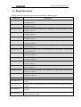
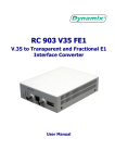
RC801-30B-FV35, RC803-30B-FV35,
RC805-30B-FV35 Series
Standalone V.35 Interface
Fiber Optic Modem
User Manual
REV.N
Raisecom Technology Co., Ltd.
(05/2006)
Raisecom Technology Co., Ltd
1. Cautions
Please read the following notices carefully before installing
and using the device. Raisecom does not respond to any loss
that caused by violating safety notice.
RC801/803/805-30B-FV35
series
device
provides
V.35
synchronization data interface which complied with ITU
standard. Please firstly connect the V.35 cable before the
device power on. It is seriously forbidden to insert or pull out
V.35 cable when the converter and the other end device are
both power on, otherwise the V.35 interface will be damaged.
This device also provides high sensitive optical interface.
Before connect this device to Fiber media converter please
test the transmitting optical power of the latter. If the optical
power is beyond the overload point of this device please don’t
connect them, otherwise the optical module will be damaged.
There must be grounding protection for the sake of safety and
stability. Do not disassemble the device yourself, we regard it
as you waiver your rights of repair guarantee.
1
Raisecom Technology Co., Ltd
Contents
1.
Cautions.................................................................................................................... 1
2.
Overview ................................................................................................................... 4
2.1.
2.2.
2.3.
3.
Parameters ............................................................................................................... 7
3.1.
3.2.
3.3.
3.4.
3.5.
3.6.
4.
Introduction ......................................................................................................... 4
Main features ...................................................................................................... 4
Model Description ............................................................................................... 5
V.35 Interface Specification................................................................................. 7
Fiber Optic Interface Specification ...................................................................... 7
Cable Type.......................................................................................................... 7
Power Supply & Power Consumption ................................................................. 8
Dimensions ......................................................................................................... 8
Ambience............................................................................................................ 8
How to use ................................................................................................................ 9
4.1. Description of the Front Panel ............................................................................ 9
4.1.1. Power Supply/Error Code Test Indicator...................................................... 9
4.1.2. Fiber Interface Alarm Indicator..................................................................... 9
4.1.3. V.35 Interface Data Channel Indicator ....................................................... 10
4.1.4. Fiber Interface ............................................................................................11
4.2. Description of the Back Panel............................................................................11
4.2.1. Power Supply Switch ..................................................................................11
4.2.2. Power Connector ........................................................................................11
4.2.3. V.35 Connector .......................................................................................... 12
4.3. Dip-switch on the bottom .................................................................................. 12
4.3.1. Setup of Timeslot Dip-switch (SW1 to SW4).............................................. 13
4.3.2. Function Dip-switch (SW5) ........................................................................ 14
4.3.3. Function Dip-switch (SW6) ........................................................................ 17
4.4. Relationship of Dip-switch Configuration and Software Configuration .............. 18
4.5. Basic Connection Type ..................................................................................... 18
4.5.1. Point-to-point, ‘Master Clock – Slave Clock’ Topology ............................... 18
4.5.2. Point-to-point ‘Terminal Clock – Slave Clock’ Topology ............................. 18
4.5.3. Extended Connection Type........................................................................ 19
5.
Installation & Preparation ........................................................................................ 20
5.1.
5.2.
5.3.
5.4.
6.
Before installation ............................................................................................. 20
Cautions before Applying the Power Supply ..................................................... 20
Equipment Deployment..................................................................................... 20
Connection Diagnoses...................................................................................... 20
F & Q ...................................................................................................................... 21
Appendix A: Introduction of Cable Making ...................................................................... 23
2
Raisecom Technology Co., Ltd
1.
2.
CBL-V35-M34M/M34F-D Cable making Instruction ............................................. 23
CBL-V35-M34M/M34M-X-D Cable making Instruction ......................................... 23
3
Raisecom Technology Co., Ltd
2. Overview
2.1. Introduction
RC801/803/805-30B-FV35 series device is PDH fiber optic modem which is deployed to
transmit V.35 signals and transparent E1 data line on fiber. It also provides solution for
Router remote connection and is widely used in constructing Wide Area Networks.
RC801/803/805-30B-FV35 series device is standalone dual interface fiber optic modem
which can be placed on desktop and has individual power supply. It is used in pairs and
provides conversion between V.35 interface to fiber interface. It can also connect to
RC802/804/806-30B series fiber optic modem module which is inserted in RC002-16 or
RC002-4 chassis to realize SNMP network management and consequently manages
remote devices.
2.2. Main features
The first tributary of client side provides one ITU standard V.35 synchronized data
DCE interface.
It provides single strand or dual strand transmission fiber.
It realizes V.35 interface bandwidth adjustment using ITU-T G.704 frame structure.
It provides the complete fiber line alarm and internal E1 detection alarm as well as
the local and remote line alarm indication.
It provides the local and remote loopback detection function to check the circuit and
device and perform the maintenance.
Support internal E1 data channel’s fractional /unframed (transparent) transfer
mode. It can distribute timeslot freely in fractional mode.
Provides three clock mode: master clock(internal clock),slave clock(follow fiber line
clock),V.35 terminal clock( follow V.35 interface clock).
When use fractional mode in a pair, the remote timeslot can follow local timeslot’s
configuration.
Internal error code test unit can make line detection and line test with several kinds
of loop-back type.
In fractional mode PCM30/PCM31 mode are optional and CRC4 verification function
is auto-negotiation.
Provide phase adjustment function of V.35 receiving data.
Provide Fault pass function to transfer alarm of data line to V.35 interface, so that to
judge E1 signal errors through router.
Very large scale ASIC chips, low consumption; four level PCB design, high reliability.
4
Raisecom Technology Co., Ltd
2.3. Model Description
RC800-30B-FV35 series fiber optic modem includes the following types:
Model Type
RC801-30B-FV35-S1(AC)
Description
Standalone at the Customer Premises, one V.35 interface(M 34), one Optical interface,
SM Dual
strand(DSC),0-25km, AC
RC801-30B-FV35-S1(DC)
Standalone at the Customer Premises, one V.35 interface(M 34), one Optical interface,
SM Dual
strand(DSC),0-25km, DC
RC801-30B-FV35-S2(AC)
Standalone at the Customer Premises, one V.35 interface(M 34), one Optical interface,
SM Dual
strand(DSC),10-60km, AC
RC801-30B-FV35-S2(DC)
Standalone at the Customer Premises, one V.35 interface(M 34), one Optical interface,
SM Dual
strand(DSC),10-60km, DC
RC801-30B-FV35-S3(AC)
Standalone at the Customer Premises, one V.35 interface(M 34), one Optical interface,
SM Dual
strand(DSC),15-120km, AC
RC801-30B-FV35-S3(DC)
Standalone at the Customer Premises, one V.35 interface(M 34), one Optical interface,
SM Dual
strand(DSC),15-120km, DC
RC803-30B-FV35-S1(AC)
Standalone at the Customer Premises, one V.35 interface(M 34), one Optical interface, SM Single strand
1310(SC-PC),0-25km, AC
RC803-30B-FV35-S1(DC)
Standalone at the Customer Premises, one V.35 interface(M 34), one Optical interface, SM Single strand
1310(SC-PC),0-25km, DC
RC803-30B-FV35-S2(AC)
Standalone at the Customer Premises, one V.35 interface(M 34), one Optical interface, SM Single strand
1310(SC-APC),10-50km, AC
RC803-30B-FV35-S2(DC)
Standalone at the Customer Premises, one V.35 interface(M 34), one Optical interface, SM Single strand
1310(SC-APC),10-50km, DC
RC805-30B-FV35-S1(AC)
Standalone at the Customer Premises, one V.35 interface(M 34), one Optical interface, SM Single strand
1550(SC-PC),0-25km, AC
RC805-30B-FV35-S1(DC)
Standalone at the Customer Premises, one V.35 interface(M 34), one Optical interface, SM Single strand
1550(SC-PC),0-25km, DC
RC805-30B-FV35-S2(AC)
Standalone at the Customer Premises, one V.35 interface(M 34), one Optical interface, SM Single strand
1550(SC-APC),10-50km, AC
RC805-30B-FV35-S2(DC)
Standalone at the Customer Premises, one V.35 interface(M 34), one Optical interface, SM Single strand
1550(SC-APC),10-50km, DC
RC802-30B-FV35-S1
RC802-30B-FV35-S2
RC802-30B-FV35-S3
RC804-30B-FV35-S1
Module type, one V.35 interface (HDB 26 male ), one optical port, dual-fiber single mode (DSC),
0-25Km
Module type, one V.35 interface (HDB 26 male ), one optical port, dual-fiber single mode (DSC),
10-60Km
Module type, one V.35 interface (HDB 26 male ), one optical port, dual-fiber single mode (DSC),
15-120Km
Module at central office, one V.35 interface (HDB 26 male ), one optical port, single fiber single
mode 1310 (SC-PC), 0-25Km
5
Raisecom Technology Co., Ltd
RC804-30B-FV35-S2
RC806-30B-FV35-S1
RC806-30B-FV35-S2
Module at central office, one V.35 interface (HDB 26 male ), one optical port, single fiber single
mode 1310 (SC-APC), 10-50Km
Customer premises module, one V.35 interface (HDB 26 male ), one optical port, single fiber
single mode 1550 (SC-PC), 0-25Km
Customer premises module, one V.35 interface (HDB 26 male ), one optical port, single fiber
single mode 1550 (SC-PC), 10-50Km
The content with shadow background in above table are the device types described in this
manual. And others are modular type devices.
The following products can work in pairs:
Central office module
Customer premises module
RC802-30B-S1
RC802-30B-FV35-S1
RC801-30B-FV35-S1
RC801-30B-FV35-S1
RC802-30B-S2
RC802-30B-FV35-S2
RC801-30B-FV35-S2
RC801-30B-FV35-S2
RC802-30B-S3
RC802-30B-FV35-S3
RC801-30B-FV35-S3
RC801-30B-FV35-S3
RC804-30B-S1
RC804-30B-FV35-S1
RC805-30B-FV35-S1
RC803-30B-FV35-S1
RC804-30B-S2
RC804-30B-FV35-S2
RC805-30B-FV35-S2
RC803-30B-FV35-S2
6
Raisecom Technology Co., Ltd
3. Parameters
3.1. V.35 Interface Specification
Physical Characteristics:
Connector Type:
Working Mode:
Interface Bit Rate:
Complies with V.35 interface standard of ITU suggestions
ISO2593 female connector (M 34 interface)
DCE (support cross connection with other DCE device)
V.35 interface bit rate is N×64Kbps(N=1~31)at E1 fractional
mode;
V.35 interface bit rate is 2048Kbps at E1 transparent mode
3.2. Fiber Optic Interface Specification
Bit rate:
Line code:
Fiber connecter:
100Mbps
4B5B
SC
Model Type
Transmission
Wavelength
(Nm )
Laser
Type
Receiver
Type
Launch
Power
(dBmW)
Over
Load
Point
(dBm)
Receiving
Sensitivity
(dBmW )
Typical
Transmission
Distance
(Km)
RC801-30B-FV35-S1
1310
FP
PIN
-15,-8
>-8
<-34
0-25
RC801-30B-FV35-S2
1310
FP
PIN
-5,0
>-8
<-34
10-60
RC801-30B-FV35-S3
1550
DFB
PIN
-5,0
>-10
<-36
15-120
RC803-30B-FV35-S1
1310
FP
PIN
-12,-3
>-8
<-30
0-25
RC805-30B-FV35-S1
1550
DFB
PIN
-12,-3
>-8
<-30
10-50
RC803-30B-FV35-S2
1310
FP
PIN
-5,0
>-8
<-32
0-25
RC805-30B-FV35-S2
1550
DFB
PIN
-5,0
>-8
<-32
10-50
3.3. Cable Type
When connect this series product with DTE equipments such as routers through M34
interface, please use the special DTE router cable. When the cable is not long enough
please order the extended cable CBL-V35-M34M/M34F-D from Raisecom (in Appendix).
When connecting this series product with other DCE equipments, the cross cable
CBL-V35-M34M/M34M-X-D is necessary, and please order it from Raisecom (in
Appendix).
7
Raisecom Technology Co., Ltd
3.4. Power Supply & Power Consumption
Power Supply:
DC –48V, tolerance range is from –36V to –72V
DC +24V, tolerance range is from +18 V to +36V
AC 220V, tolerance range is from 165V to 265V
Power Consumption: ≤ 5W
3.5. Dimensions
Standalone equipment can be placed on the table.
Dimension: 142 (width) x 38 (height) x 187 (depth) mm
3.6. Ambience
Working Temperature: 0 ~ 45℃
Humidity: ≤90%(25℃)
8
Raisecom Technology Co., Ltd
4. How to Use
4.1. Description of the Front Panel
RC800-30B-FV35 SERIES
V35
LOS
PWR/PAT
TX
RX
LOF TD
LOF
AIS
ERR
CRC LOOP RD
View of the front panel
4.1.1. Power Supply/Error Code Test Indicator
PWR/PAT Green/Yellow:
Steady Green, built-in power works in good condition.
Yellow, when using built-in error code test function, if the fiber interface receives its own
sending pseudo random sequence data the indicator will be in steady yellow. When it gets
an error code the indicator will turns to green for at least 1 second.
Steady off, the device is power off.
4.1.2. Fiber Interface Alarm Indicator
LOS Red:
Steady light: Local optical receiving signal is lost;
Periodically flash: Remote optical receiving signal is lost;
Steady off: Local/remote optical receiving signal is normal.
LOF Red:
Steady light: Local optical receiving signal is out of frame;
Periodically flash: Remote optical receiving signal is out of frame;
Steady off: Local/remote optical receiving signal is not out of frame.
ERR Yellow:
Steady light: There is 1E-6 error code alarm in local optical receiving signal;
Periodically flash: There is 1E-6 error code alarm in remote optical receiving signal;
Non-periodically flash: There is 1E-3 error code alarm in remote or local optical
receiving signal;
Steady off: There is no error code alarm in local/remote optical receiving signal.
9
Raisecom Technology Co., Ltd
4.1.3. V.35 Interface Data Channel Indicator
AIS Red:
Steady Light: There is AIS alarm in E1 data channel of local optical receiving signal;
Flash: There is AIS alarm in E1 data channel of remote optical receiving signal;
Steady Off: There is no AIS alarm in E1 data channel of local/remote optical receiving
signal;
CRC Red:
Steady Light: There is CRC4 checkout alarm in E1 data channel of local optical
receiving signal;
Flash: There is CRC4 checkout alarm in E1 data channel of remote optical receiving
signal;
Steady Off: There is no CRC4 checkout alarm in E1 data channel of local/remote
optical receiving signal;
LOF Red:
Steady Light: There is G.704 out of frame alarm in E1 data channel of local optical
receiving signal;
Flash: There is G.704 out of frame alarm in E1 data channel of remote optical
receiving signal;
Steady Off: There is no G.704 out of frame alarm in E1 data channel of local/remote
optical receiving signal;
LOOP Yellow:
Steady Light: Local bidirectional loopback indication;
Flash: Remote bidirectional loopback indication;
Steady Off: There is no loopback in local/remote side.
TD Green:
Flash: There is data transmission in V.35 interface, and the flash frequency stands for
the different bit rate of V.35 interface. When the bit rate is 64Kbps the flash frequency is
lowest and the 2048Kbps the highest.
Steady Off: There is no transmission in V.35 interface.
RD Green:
Flash: There is data receiving in V.35 interface, and the flash frequency stands for the
different bit rate of V.35 interface. When the bit rate is 64Kbps the flash frequency is
lowest and the 2048Kbps the highest.
Steady Off: There is no receiving data in V.35 interface.
Notice: This device provides CRC4 checkout’s auto-negotiation function. If there is CRC4
checkout signal in E1 data of optical interface the CRC4 checkout function will be enabled
automatically, and the CRC alarm indicator will be available when there is CRC4 error. On
10
Raisecom Technology Co., Ltd
the contrary, if there is no CRC4 checkout signal in E1 data of optical interface the CRC4
checkout function will be disable and CRC alarm indicator unavailable.
4.1.4. Fiber Interface
For RC801-30B-FV35 dual strand device, TX stands for optical signal output (transmit)
and RX stands for input (Receive).
For RC803/5-30B-FV35 single strand device, TX and RX has no actual meanings. In one
fiber the transmission and receiving can be distinguished by different wave length.
4.2. Description of the Back Panel
V35
Back Panel of the AC Device
V35
-48V PGND BGND
Back Panel of the DC Device
4.2.1. Power Supply Switch
I stands for ON, O stands for OFF
4.2.2. Power Connector
AC Power connector: It is the standard three-phase power connector. Please make sure
that the grounding is correct. If your AC power supply has no grounding signal please
11
Raisecom Technology Co., Ltd
connect the grounding end on the right of the device to the protection grounding of the
center office.
DC Power connector: It has three connection end: -48V, PGND and BGND. Please make
sure that the PGND end is connected to protection grounding. The grounding end on the
right of the device and the PGND are internally connected, so it is enough to connect any
of it to protection grounding.
4.2.3. V.35 Connector
Left figure is a standard ISO2593 connector of V.35
interface. This device has a DCE Connector Face-34 Pin
Female connector which can be connected to standard
DTE cable.
The description of this connector is as following table:
I-Input O-Output
Signal Name
I/O
Pin Name
Chassis Ground — CGND
-
A
Signal Ground — GND
-
B
Receive Data (A) — RD(A)
O
R
Receive Data (B) — RD(B)
O
T
Receive Timing (A) — RCK(A)
O
V
Receive Timing (B) — RCK(B)
O
X
Send Data (A) — TD(A)
I
P
Send Data (B) — TD(B)
I
S
Send Timing (A) — TCK(A)
O
Y
Send Timing (B) — TCK(B)
O
AA
Terminal Timing (A) — SCTE(A)
I
U
Terminal Timing (B) — SCTE(B)
I
W
Request to Send — RTS
I
C
Clear to Send — CTS
O
D
Data Set Ready — DSR
O
E
Data Carrier Detect — DCD
O
F
Data Terminal Ready — DTR
I
H
4.3. Dip-switch on the bottom
ON
ON
DIP
There are six group eight-bit dip-switches that are SW1, SW2,
SW3, SW4, SW5, and SW6 on the bottom of the device. The
configuring of these dip-switches must be performed
OFF
12345678
12
Raisecom Technology Co., Ltd
before power on! If the switches are configured during running status, the device
must be restarted to make the configuration effective. Each dip-switch is shown as the
left figure. The DOWN indicates OFF and UP indicates ON when from left to right the bit is
1st to 8th. There is also a note pasted on the bottom of the device as the following figure:
SW1
V.35 Port
SW2
SW3
SW4
SW5
Optic
Port
SW6
Power
Interface
Power
Switch
Configuration Note on the device bottom
4.3.1. Setup of Timeslot Dip-switch (SW1 to SW4)
Timeslot switches are SW1, SW2, SW3 and SW4.
“√” indicates enable; “×” indicates disable
SW1 definition (default is all OFF)
1st bit
2nd bit
3rd bit
4th bit
5th bit
6th bit
7th bit
8th bit
SET
Frame Status
TS1
TS2
TS3
TS4
TS5
TS6
TS7
ON
Fractional
√
√
√
√
√
√
√
OFF
Unframed
×
×
×
×
×
×
×
SW2 definition (default is all OFF)
1st bit
2nd bit
3rd bit
4th bit
5th bit
6th bit
7th bit
8th bit
SET
TS8
TS9
TS10
TS11
TS12
TS13
TS14
TS15
ON
√
√
√
√
√
√
√
√
OFF
×
×
×
×
×
×
×
×
3rd bit
4th bit
5th bit
6th bit
7th bit
8th bit
SW3 definition (default is all OFF)
1st bit
2nd bit
13
Raisecom Technology Co., Ltd
SET
TS16
TS17
TS18
TS19
TS20
TS21
TS22
TS23
ON
√
√
√
√
√
√
√
√
OFF
×
×
×
×
×
×
×
×
SW4 definition (default is all OFF)
1st bit
2nd bit
3rd bit
4th bit
5th bit
6th bit
7th bit
8th bit
SET
TS24
TS25
TS26
TS27
TS28
TS29
TS30
TS31
ON
√
√
√
√
√
√
√
√
OFF
×
×
×
×
×
×
×
×
Notice:
When the SW1-1 is OFF (unframed mode) the TS1 to TS31 is invalid.
When the SW1-1 is ON( Fractional mode) the TS1 to TS31 bits are valid and can not
be all OFF. That is to say there must be some timeslot which is enabled.
4.3.2. Function Dip-switch (SW5)
In below table “√” indicates enable; “×” indicates disable
Definition of SW5 (The 1st and 2nd bits are ON in default and others are OFF)
1st bit
2nd bit
3rd bit
4th bit
5th bit
6th bit
7th bit
8th bit
Set
Timing1
Clock
1st
Timing2
Clock
2nd
TS_FLOW
Timeslot
Follow
BET
Error
Code
Test
RX CLK
Phase
LP_EN
Two
direction
loop back
LP_SEL
Loop back
position
Reserved
N/A
ON
*
*
√
√
Reverse
√
Local
-
OFF
*
*
×
×
Positive
×
Remote
Normal
1. The 1st and 2nd bit: Clock mode choosing dip-switch Timing1, Timing2 (default is
ON)
The Clock mode is defined by the 1st bit and 2nd bit of SW5, detail is shown in below table:
SW5-1
SW5-2
Clock Mode
OFF
OFF
Master Clock (Internal clock)
OFF
ON
ON
OFF
V.35 terminal Clock ( Follow V.35 interface
clock)
ON
ON
Slave Clock ( Follow fiber line clock)
2. The 3rd bit: Timeslot auto follow function TS_FLOW (default OFF)
SW5-3
Timeslot auto follow function
ON
Enable
14
Raisecom Technology Co., Ltd
OFF
Disable
To make local timeslot follow remote timeslot, below three conditions should be ensured:
(1) This series device is used point to point in pair.
(2) There is no PCM device which occupy the Sa bit linked in E1 line.
(3) Local device works on slave clock mode.
When all of above condition is satisfied, setting the SW5-3 of local device as ON to open
timeslot auto-follow function, the timeslot and frame mode (PCM30/PCM31) of local
device will follow the configurations of remote device automatically.
3. The 4th bit: Error code test function choosing dip-switch BET (default OFF)
SW5-4
Internal Error Code Test Function
ON
Enable
OFF
Disable
There is an error code test unit inside this series device, and the main purpose of this unit
is producing pseudo random sequence (2E15-1 STD) and sending them to optical line.
This sequence can be uploaded to proper data channel by configuration, and then via
many loopback modes the returned sequence is sent to device for testing. The testing
result will be displayed by the PWR/PAT indicator on front panel. When error code is
captured the PWR/PAT indicator will turn to green and keep for at least one second. If
there is no new error code occurs the PWR/PAT indicator will come back to steady yellow
status.
The device will add test sequence to user data channel after the error code test function is
enabled. This function is available in fractional mode and unframed (transparent) mode,
and when this function is enabled the V.35 operation will intermit.
Notice: The error code test function can be operated with many loop back tests. When the
local bidirectional loop back function is disabled the loop back can be simulated by fiber,
but the dual-fiber S3 and all single fiber device can not. At the time if PWR/PAT indicator is
steady yellow, it indicates that correct test code was received. If the remote bidirectional
loop back is enabled accompanied with error code test, it means the whole information
process will be tested.
4. The 5th bit: V.35 RX CLK Phase Choosing Dip-switch (default OFF)
SW5-5
Phase Choosing
ON
RX CLK Reverse Phase
OFF
RX CLK Positive Phase
The RX CLK phase choosing is provided because of the different V.35 clock and data
phase of different brand router. On Cisco series router the test result of V.35
15
Raisecom Technology Co., Ltd
synchronization WAN interface is passing when this device is connected and its RX CLK
is Positive.
RX CLK is Positive: Data will be sent to RD signal during RX CLK falling edge.
RX CLK
RD
RX CLK is Reverse: Data will be sent to RD signal during RX CLK rising edge.
RX CLK
RD
Notice: The relationship of TX CLK and TD phase of this series device is auto-adjusted, so
users need not to configure it.
5. The 6th, 7th and 8th bit: Loop back dip-switch (default OFF)
SW5-6
DTE or Error code
equipment
SW5-7
ON
Dual-direction
loopback enable
Local loopback
OFF
Dual-direction
loopback disable
Remote loopback
V.35
Local
(Master)
Fiber
Remote
(Slave)
DTE or Error code
equipment
Local loop back: it actually includes local two direction loop back. Those are internal loop
back on V.35 interface and external loop back on fiber interface, as above figure.
To perform local loop back test please set SW5-6 and SW5-7 as ON. The interface inquiry
result of local and remote router is loop back if the fiber and V.35 cable is good.
DTE or Error code
equipment
V.35
Local
(Master)
Fiber
Remote
(Slave)
DTE or Error code
equipment 仪
Remote loop back: it actually includes remote two direction loop back. Local device’s fiber
interface loop back toward local device and its V.35 interface loop back toward DTE
equipment, as above figure.
6. The 8th bit: Reserved (default OFF)
16
Raisecom Technology Co., Ltd
Please keep OFF when the device works normally.
4.3.3. Function Dip-switch (SW6)
Set
ON
OFF
1st bit
2nd bit
3rd bit
4th bit
Fault
Pass
Enable
Disable
Reserved
Reserved
Reserved
5th bit
6th bit
7th bit
Configuration of vendor
8th bit
Forbidden to be changed by users
Normal
Normal
Normal
1. The 1st bit: Fault Pass dip-switch (Default is OFF)
SW6-1
Fault Pass Function
ON
Enable
OFF
Disable
When the fault pass function is enabled, the alarms on fiber receiving side and
transmitting side will be transferred to DCD and CTS signals on V.35 interface; when the
fault pass function is disabled, the DSR, DCD and CTS signals on V.35 interface will be
always valid.
When the fault pass function is enabled, and if there is local alarm on fiber optic modem,
that is to say there are errors on fiber receiving side, the DCD signal of V.35 interface will
be closed and DTE device will have some reflection.
When the fault pass function is enabled, and if there is remote alarm on fiber optic modem,
that is to say there are errors on fiber transmitting side, the CTS signal of V.35 interface
will be closed and DTE device will have some reflection.
The DSR signal of this series device will be always valid after power on.
2. the 2nd, 3rd and 4th bit: Reserved (Default is OFF)
These bits are reserved for testing and they should be all OFF when the device works
normally.
3. the 5th, 6th, 7th and 8th bit: Vendor configuration bits
These bits are configured by vendor during the producing process and should not be
changed by users.
17
Raisecom Technology Co., Ltd
4.4. Relationship of Dip-switch Configuration and Software
Configuration
The relationship of dip-switch configuration and software management ability is shown in
below table:
Dip-switch
Whether the software can change dip-switches’ configuration
or not
SW1~SW4
Can
SW5
Can
SW6
Can Not
4.5. Basic Connection Type
The connection topologies introduced in this part is only for user reference. Users are
advised to design and deploy the most appropriate topology according to their specific
environment.
4.5.1. Point-to-point, ‘Master Clock – Slave Clock’ Topology
When connecting Routers or other V.35 interface equipment point to point, routers should
work in DTE mode. For the convenience of installation and test, it is advised to set the
local modem ‘Master Clock Mode’, and remote modem ‘Slave Clock Mode’. That is to say
the timing resource is from the local V.35 interface modem.
In “Master Clock-Slave Clock” topology, if DXC, MUX devices are in E1 link, the DXC,
MUX and remote modem should all be slave clock mode (follow the clock of E1 link)
Master
Clock
(Clock Source)
Fiber
RC802-30BFV35
Slave
Clock
RC801-30BFV35
V.35 DTE wire
V.35 DTE wire
Router
Router
4.5.2. Point-to-point ‘Terminal Clock – Slave Clock’ Topology
When the remote DTE device must follow the timing resource of local DTE device’s clock,
that is to say the TX CLOCK of local DTE is internal clock source, it is advised to set the
18
Raisecom Technology Co., Ltd
local V.35 interface modem ‘Terminal Clock Mode’, and remote V.35 interface modem
‘Slave Clock Mode’.
In “Terminal Clock-Slave Clock” topology, if DXC, MUX devices are in E1 link, the DXC,
MUX and remote V.35 interface modem should all be slave clock mode (follow the clock of
E1 link).
Terminal
Clock
Slave
Clock
Fiber
RC802-30BFV35
RC801-30BFV35
V.35 DTE wire
V.35 DTE wire
Router
Router
Clock Source
4.5.3. Extended Connection Type
Fiber
E1
RC802-30B-FV35
RC 802-30B
V.35 DTE wire
E1 cable
Router
ATM /DDN/Router
If E1 interface equipment is in user premise, RC802-30B can be in remote site and
RC802-30B-FV35 in local site as the above figure. Please be attention to the clock mode,
if the E1 interface of ATM is in master clock mode, then local RC802-30B-FV35 should be
in slave clock mode.
19
Raisecom Technology Co., Ltd
5. Installation & Preparation
5.1. Before installation
Please make sure that your V.35 cable matches the equipment you want to connect
Please check whether the equipment has been destroyed
If you do not use network management, please configure the device through
DIP-switch before installation.
5.2. Cautions before Applying the Power Supply
It is strictly forbidden to hot-swap the V.35 interface cable.
If adopts the DC –48V power supply, please firstly connect the Protecting Ground (the
middle pin PGND). They must not be reversely connected, connect -48V with low
voltage input, BGND with high voltage input.
5.3. Equipment Deployment
Keep the center office clean
The deployment and settlement should be in order.
Configure the clock mode, time slot, master/slave setting and other parameters
according to the specific connection type.
5.4. Connection Diagnoses
Check whether there is any alarm on local equipment
Test whether data communication can be performed between local DTE and remote
equipment
If the test is failed, please try the following steps.
1. Local bidirectional loopback test. Refer to previous dip-switch setup for configuration
details or configure by software. If the Router indicates loopback successful, the V.35
interface is working in good condition. If the Router indicates loopback fails, please
firstly check the timing resource and bandwidth setup at local site, and then try to
adjust the TX CLK and RX CLK phase option switch.
2. If the E1 interface of remote equipment is connected with the ATM E1 interface,
please make sure that there is only on clock source in the network and the time slot
configuration of both equipments is the same.
20
Raisecom Technology Co., Ltd
6. F & Q
If there is any problem during installation and operation, please try the following solutions.
If the problems still cannot be solved, please contact distributors for technical support.
Power/Error code test indicator (PWR/PAT) is not on
Answer: Power supply fails. Check whether the power supply of chassis is working
properly.
In unframed mode there is AIS alarm after connecting the fiber
Answer: In unframed mode the AIS alarm indicator will be steady on when optical
interface receives AIS. It may be caused by E1 line intermit .If the line works normal,
please check the following conditions: V.35 interface of remote site device does not
connect to router, remote router is powered off or V.35 interface of remote router is
shutdown. When work with few venders’ router, there maybe yellow steady on or
interval on, but they can communicate with each other. It is because few remote
routers will send AIS when there is no data transporting. If this exceptional
phenomenon doesn’t affect communication please ignore it.
V.35 Interface Data channel alarm
Answer: If there is LOF and CRC alarm please check the line quality, clock mode,
framed mode and etc. You can use the internal error code test function and loopback
function to check the device and the line.
Enable loopback function, using the internal error code tester and power on,
but the status of PWR/PAT is not stable.
Answer: Firstly make sure that the connection of optical interface is normal and there
is no error code, and then make sure there is no loopback configuration on remote
site equipment. In the first 15 seconds after being powered on, the local and remote
equipments will change information with each other, so the unstable indicator is
normal. Please wait for some moments and then judge error code status according to
PWR/PAT indicator.
PRI of network management and DIP-switch
Answer: CPU will read the DIP-switch configuration when it is powered on, and then
network management has higher privilege. (Notice that network management cannot
configure Fault-Pass function)
Severe Packet Loss
Answer: This may be caused by the following conditions:
There is more than one clock source in the network;
Check the status of router’s V.35 interface, if there is RX/TX data error, please adjust
RX CLK phase of local and remote device.
21
Raisecom Technology Co., Ltd
Compatibility
Answer: The optical interface of this equipment deploys PDH technology, so the optical
interface can only communicate with Raisecom RC800 series optical modem. But if the
remote site is E1 interface fiber optic modem, the E1 interface can communicate with all
the other venders’ equipments.
Compatibility of V.35 interface
Answer: RC800-30B-FV35 series can work with other Raisecom V.35 equipments,
and can provide a flexible network topology, including:
Standalone RC903-V35FE1 V.35 to fractional E1 interface converter
Modular RC904-V35FE1 V.35 to fractional E1 interface converter
SUBM-FV35 (N×64K V.35) card which is installed in extension slot of some
Raisecom optical multiplexer
22
Raisecom Technology Co., Ltd
Appendix A: Introduction of Cable Making
1. CBL-V35-M34M/M34F-D Cable making Instruction
This cable is used to extend V.35 cable if the DET cable is not long enough.
Converter
DCE
Router
DTE
CBL-V35-M34M/M34F-D
User DTE cable
When you order this cable from Raisecom or our agency please make sure the length you
want.
If you want to make the cable by yourself please refer to below table:
ISO2593Male(M34M)
V.35 STD Name
ISO2593 Female(M34F)
A
PGND
A
P
TD(A)
P
R
RD(A)
R
C
RTS
C
D
CTS
D
E
DSR
E
B
GND
B
F
DCD
F
S
TD(B)
S
Y
TCP(A)
Y
W
SCTE(B)
W
V
RCP(A)
V
H
DTR
H
T
RD(B)
T
AA
TCP(B)
AA
U
SCTE(A)
U
X
RCP(B)
X
Other pins have no connection.
Request: The cable material is not lower than 80℃ 30V.
2. CBL-V35-M34M/M34M-X-D Cable making Instruction
This cable is cross connection cable which is used to link the V.35 (DCE) interface of
node equipment such as DDN to the V.35 interface of the RC802-30B-FV35 series
23
Raisecom Technology Co., Ltd
device. When using this cable if the clock source is provided by node equipment the
RC802-30B-FV35 series device should be configured to V.35 terminal mode. If the
clock is provided by fiber optic modem, the node equipment’s clock should be slave
mode.
Converter
DCE
CBL-V35-M34M/M34M-X-D
User DTE Cable
Node
Equipment
DCE
When you order this cable from Raisecom or our agency please make sure the length you
want.
If you want to make the cable by yourself please refer to below table:
The two ends of the cable are both M34 connector.
Signal Name Pin NO.
TD (A)
P
TD (B)
S
RD (A)
R
RD (B)
T
RCLK (A)
V
RCLK (B)
X
SCTE (A)
U
SCTE (B)
W
SGND
GND
TCLK (A)
TCLK (B)
A
B
Y
AA
DCD
DSR
CTS
RTS
DTR
F
E
D
C
H
N/A
N/A
Pin NO.
R
T
P
S
U
W
V
X
Signal Name
RD (A)
RD (B)
TD (A)
TD (B)
SCTE (A)
SCTE (B)
RCLK (A)
RCLK (B)
A
B
Y
AA
SGND
GND
TCLK (A)
TCLK (B)
F
E
D
C
H
Other pins have no connection.
Request: The cable material is not lower than 80℃ 30V.
24
DCD
DSR
CTS
RTS
DTR
Raisecom Technology Co., Ltd
BROADBAND
to RAISECOM
@2005 Raisecom Technology Co., Ltd.
All trademarks are the property of their respective owners.
Technical information may be subject to change without prior notification.
25