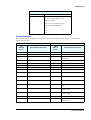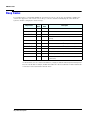
1
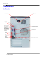
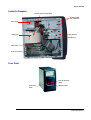
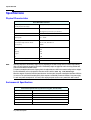
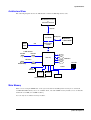
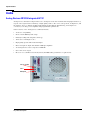
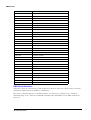
technical
reference
manual
product description
hp vectra xe310
series 2
hp desktop pcs
www.hp.com/go/vectrasupport
Notice
The information contained in this document is subject to change without notice.
Hewlett-Packard makes no warranty of any kind with regard to this material, including, but not limited
to, the implied warranties of merchantability and fitness for a particular purpose. Hewlett-Packard shall
not be liable for errors contained herein or for incidental or consequential damages in connection with
the furnishing, performance, or use of this material.
This document contains proprietary information that is protected by copyright. All rights are reserved.
No part of this document may be photocopied, reproduced, or translated to another language without
the prior written consent of Hewlett-Packard Company.
Symbios® is a registered trademark of LSI Logic Corporation.
Adobe® and Acrobat® are registered trademarks of Adobe Systems Incorporated.
Microsoft®, MS-DOS®, Windows® and Windows NT® are U.S registered trademarks of Microsoft
Corporation.
WOL™ (Wake on LAN) is a trademark of IBM Corporation.
Celeron™ is a trademark and Intel® and Pentium® are registered trademarks of Intel Corporation.
Adaptec® is a trademark of Adaptec Incorporated.
Analog Devices is a trademark of Analog Devices, Inc.
HP France
Business Desktop Division
38053 Grenoble Cedex 9
France
© 2001 Hewlett-Packard Company
How to Recognize Your HP Vectra XE310 Model and Series
There are two versions of the HP Vectra XE310 PC: the HP Vectra XE310 and HP Vectra XE310 Series 2.
If you are uncertain of which HP XE310 model and series you have, this information can be found on the
label on the side of the PC case, as shown here.
This manual provides information about the HP Vectra XE310 Series 2 only.
Information Roadmap
Use the
icon in Acrobat Reader to search for information in this PDF.
The following types of information are available for HP Business PCs:
Technical Reference
See the HP Technical Reference Manual.
This Technical Reference Manual is a technical reference and BIOS document for personnel providing
system level support. It is available in PDF format on the HP support web site
(www.hp.com/go/vectrasupport)
It is presented in modular form to provide quick and easy access to technical information on the HP
Business PC. It is made up of the following components:
•
The Introduction & HP Business PC Overview provides a quick reference guide to the hardware
components and BIOS used in the latest HP Business PCs. It also lists some of the available
accessories.
•
Product Description (this document). Provides technical information specific to a HP Business PC.
This includes summary information on product hardware and detailed information on the BIOS. Read
this manual to see which hardware components are in the PC.
•
HP Business PC Technology. Provides an in-depth guide to the hardware in all of the featured HP
Business PCs. Subjects covered include chipsets, processors, graphics controllers, hard disk drives
and optical drives.
product description 3
Installing, Configuring and Upgrading
See the HP Service Handbook Chapter or the HP Upgrade Guide.
The Service Handbook Chapter, available in PDF format on the HP support web site
(www.hp.com/go/vectrasupport), provides information on:
•
HP Business PC configurations
•
Replacement parts
•
Available accessories.
The Upgrade Guide will help you upgrade and replace components in your HP Business PC, including
the hard drive, memory, battery, power supply, and 5.25-inch drives. More information is available on the
HP support web site (www.hp.com/go/vectrasupport).
Troubleshooting
See the HP Troubleshooting Guide.
The Troubleshooting Guide, available in PDF format on the HP support web site
(www.hp.com/go/vectrasupport) will help you:
•
Troubleshoot your HP Business PC
•
Find out where to get more information.
Discover and use your product
See the HP Quick Start card and HP Quick User’s Guide.
The Quick Start card provided with your HP Business PC will help you:
•
Set up and begin using your HP Business PC for the first time
•
Upgrade and replace components in your HP Business PC, including the hard drive, processor
memory, add-on cards and 5.25-inch drives. More information is available on the HP support web site
(www.hp.com/go/vectrasupport).
•
Find out where to get more information.
The Quick User’s Guide provided with your HP Business PC includes basic troubleshooting information,
technical specifications, warranty and legal information.
Your computer’s online information
Your computer may contain online help information on the hard disk. It includes information on:
•
Troubleshooting and how to use HP Instant Support
•
Linking to useful HP web sites.
4 product description
Information on the hp support web site
Refer to the HP support web site (www.hp.com/go/vectrasupport) for a wide range of information,
including:
•
Downloadable documentation
•
Service and support options
•
The latest BIOS, drivers and utilities
•
Answers to Frequently Asked Questions.
System recovery cd-roms
Used for a full system recovery or alternative OS installation. Includes instructions on how to recover
your preloaded software including operating system, drivers and utilities.
Finding Information
Use the following table to determine where to locate particular types of information:
Type of Information
Location
Support phone numbers
• Technical support contact information
Quick User’s Guide
•
•
Warranty information
•
How to set it up
Quick Start Card (details)
Quick User’s Guide (general information)
•
Operation
Operating system and application manuals
•
Diagrams and detailed instructions on installing add-on devices
• Internal wire connections for adding hard drives, CD-ROM, etc.
• Memory expansion and replacing devices
Upgrade Guide
•
LAN configuration
• LAN controller
Technical Reference Manual
Identifying the problem
• Information on errors
Troubleshooting Guide
•
•
Problem solving
Troubleshooting
•
Parts list
•
Accessories list
•
BIOS
• Connectors
•
•
•
Service Handbook Chapter
Technical Reference Manual
IRQ
POST setup
Specifications
• System board layout
• Technical diagrams
•
product description 5
Bibliography
Datasheets and other information can be obtained at:
❒ Intel Chipsets
developer.intel.com
❒ Intel Dynamic Video Memory Technology
www.developer.intel.com/business/products/chipsets/dvmt_white.pdf
❒ Celeron and Pentium III Processors
www.intel.com/celeron/
www.intel.com/pentiumIII/
❒ Analog Devices AD1885
www.analogdevices.com
❒ Intel LAN card
www.intel.com/support/network
❒ Hewlett-Packard white papers are available on a variety of subjects including AGP graphics and
SDRAM memory at:
www.hp.com/go/library
6 product description
How to Recognize Your HP Vectra XE310 Model and Series 3
Information Roadmap . . . . . . . . . . . . . . . . . . . . . . . . . . . . 3
Finding Information . . . . . . . . . . . . . . . . . . . . . . . . . . . . . . 5
Bibliography . . . . . . . . . . . . . . . . . . . . . . . . . . . . . . . . . . . 6
System Overview
Package Features . . . . . . . . . . . . . . . . . . . . . . . . . . . . . . 10
Specifications . . . . . . . . . . . . . . . . . . . . . . . . . . . . . . . . . 12
System Features
XE310 Series 2 System Board Layout . . . . . . . . . . . . . . . 14
Mass Storage Devices. . . . . . . . . . . . . . . . . . . . . . . . . . . 17
Graphics . . . . . . . . . . . . . . . . . . . . . . . . . . . . . . . . . . . . . 20
Audio . . . . . . . . . . . . . . . . . . . . . . . . . . . . . . . . . . . . . . . 22
Network . . . . . . . . . . . . . . . . . . . . . . . . . . . . . . . . . . . . . 23
Modems . . . . . . . . . . . . . . . . . . . . . . . . . . . . . . . . . . . . . 24
BIOS Overview
BIOS Summary . . . . . . . . . . . . . . . . . . . . . . . . . . . . . . . . 26
Power Saving and Ergonometry. . . . . . . . . . . . . . . . . . . . 28
BIOS Addresses . . . . . . . . . . . . . . . . . . . . . . . . . . . . . . . 29
Order in Which the POST Tests are Performed. . . . . . . . . 32
Beep Codes . . . . . . . . . . . . . . . . . . . . . . . . . . . . . . . . . . . 37
Drivers and Software
Drivers . . . . . . . . . . . . . . . . . . . . . . . . . . . . . . . . . . . . . . 40
product description 7
8 product description
Status
1
System Overview
This chapter introduces the internal and external features, and lists the specifications of HP Vectra
XE310 Series 2 PCs.
System Overview
Package Features
Rear Connectors
Power connector
Voltage switch
Keyboard
Mouse
Monitor Connector
(this connector is
disabled if the PC
has a VGA graphics
card. In this case, use
the graphics card’s
connector.)
25-pin Parallel Connector
Serial Connector
Line Out
Line In
Microphone
4 USB
Connectors
10 product description
Network (LAN) connector
System Overview
Inside the Computer
Processor (under the airflow guide)
CD-ROM, CD-RW
drive, or DVD drive
Power supply
Floppy disk drive
Airflow guide
Hard disk drive
Main memory
Accessory board slots
Front Panel
Power on status light
(green)
On/Off power
button
HDD LED (yellow)
product description 11
System Overview
Specifications
Physical Characteristics
Vectra XE310 Characteristics
Weight (configuration with 1 CD-ROM drive,
excluding keyboard and display)
10 kilograms (22 pounds)
Dimensions
38.0 cm (Depth) by 21.0 cm (Width) by 39.0 cm (Height)
(14.96 inches by 8.27 inches by 15.35 inches)
Footprint
0.068 m2 (0.73 sq ft)
Acoustic noise emission (ISO 7779)
Sound pressure level at operator position
Operating (idle)
LpA ≤ 35 dBA
Power Supply
NOTE
Input voltage (voltage selection switch):
100-127 V 4A, 200-240 V 2A
Input frequency:
50/60Hz
Power consumption (115 / 60Hz and 230 / 50 Hz)
Windows XP
Max
62W
Operating
40W
Suspend
≤
5W
Off
≤
5W
Available minimum output power
149W
Storage Humidity
8% - 85% (relative)
Operating temperature and humidity ranges may vary depending on the mass storage devices installed. High humidity
levels can cause improper operation of disk drives. Low humidity ranges can aggravate static electricity problems and
cause excessive wear of the disk surface.
The power consumption and acoustics figures given in the tables above are valid for the standard configuration as shipped.
For more information, refer to the product’s data sheet at HP’s web site: www.hp.com/desktops.
When the computer is turned off with the power button on the front panel, the power consumption falls below 10W, but
it is not zero. The special on/off method used by these computers considerably extends the lifetime of the power supply.
To reach zero power consumption in “off” mode, either unplug the power outlet or use a power block with a switch.
Environmental Specifications
Environmental Specifications (System Processing Unit, with Hard Disk)
Operating Temperature
+10°C to +35°C (+50°F to 95°F)
Storage Temperature
-40°F to +70°F (-40°C to +158°C)
Operating Humidity
15% to 80% (relative)
Storage Humidity
8% to 85% (relative), non-condensing at 40°C (104°F)
Operating Altitude
10000ft (3100m) max
Storage Altitude
15000ft (4600m) max
12 product description
Status
2
System Features
This chapter describes core components of HP Vectra XE310 Series 2 PCs such as processors,
chipset, mass storage devices, graphics controllers, audio controllers, network features and
input devices.
System Features
XE310 Series 2 System Board Layout
All HP Vectra XE310 Series 2 PC system boards have a Socket 370 for a compatible Celeron or Pentium
III processor.
System Board Components
The following diagram shows where the different chips and connectors are located on the system board:
Active heatsink fan connector
Processor
socket
Keyboard
Mouse
Power supply
connector
Main
memory
slots
VGA
Parallel
Serial
Line-out
Line-in
Mic-in
PCI Slot 1
DIMM1
DIMM2
2 x USB
LAN
2 x USB
Floppy connector
IDE connectors
PCI Slot 2
PCI Slot 3
CD Audio Connector
14 product description
Clear CMOS and
clear password
jumpers
Battery Socket
System Features
Architectural View
The following diagram shows the XE310 Series 2 Intel 815EG Chip architecture:
Intel Pentium III Processor
or
Intel Celeron Processor
Host Bus
Memory Bus
Intel 815EG
Integrated Intel
82815 graphics
controller
VGA
Monitor
Output
Main Memory
133MHz SDRAM
2 UATA 100 Disks
Hard Disk
Hard Disk
ICH2 chip
4 USB Slots
2 IDE Drives
3 PCI Slots
DVD/CD-RW/Zip
CD-ROM
PCI Bus
Audio
AD1885
Super I/O
Flash BIOS
Intel LAN
Serial/Parallel/FDD/PS2
Main Memory
There are two 168-pin DIMM slots on the system board for installing main memory. You can install
133MHz SDRAM modules, these are available in 64, 128 and 256MB memory modules. You can install a
maximum of 512MB (2 x 256MB modules).
You can only use non-ECC memory modules.
product description 15
System Features
Processors
The XE310 Series 2 is equipped with either a single Socket 370 Intel Celeron or socket 370 Intel Pentium
III processor. The processor is connected to the system board through a Plastic Pin Grid Array (PPGA)
370 Socket. A heat sink covers the processor to prevent it from overheating. The reduction in size
achieved by the Socket 370 Celeron is due to the integration of the L2 cache on the processor die. Like
the Celeron processor, the Pentium III comes in a 370-pin socket (PGA370) package.
To find out more about Socket 370 Celeron and Pentium III technology, refer to the Technical Reference
Manual - PC Technology.
Accessory Board Slots
The XE310 Series 2 has three PCI accessory board slots.
PCI Slot Numbers
Your PC uses logical slot numbers in the BIOS Setup program. You need to know these logical slot
numbers if you want to change the PCI slot configuration in the Setup program. PCI slot numbers are
also indicated on the system board itself.
HP XE310 Series 2 PCI Mapping Table
Slot#
Bus
Device
PCI Device
0
0
82815 Processor to I/O controller
0
2
82815 Graphics controller
0
8
ICH2: LAN controller
0
30
ICH2: Hub interface to PCI bridge
0
31
ICH2: PCI to LPC bridge
0
31
ICH2: IDE controller
0
31
ICH2: USB controller
0
31
ICH2: SMBus controller
0
31
ICH2: AC97 audio controller
1
2
PCI slot 1
1
1
1
PCI slot 2
2
1
0
PCI slot 3
3
16 product description
System Features
Mass Storage Devices
Hard Disk Drives
A 3.5-inch hard disk drive is supplied on an internal shelf in some models. These hard drives can be
provided with the PC. To see which other hard disk drives can be purchased as accessories for the XE310
Series 2, refer to www.hp.com/go/pcaccessories.
20GB
Ultra-ATA 100
40GB
Ultra-ATA 100
Average Seek Time (ms)
read
write
9.9
9.9
10.9
10.9
Track-to-Track Seek Time in write mode (ms)
2
2
Full Stroke Seek Time in write mode (ms)
24
24
Rotational Speed (RPM)
5400
5400
Buffer Size (KB)
2000
2000
To find out about Ultra-ATA 100 hard disk drive technology, refer to the Technical Reference Manual PC Technology.
Floppy Disk Drives
All models are supplied with a 3.5-inch floppy disk drive.
Optical Drives
Models may be fitted with a 48✕ Max IDE CD-ROM drive. It can play standard CD-ROM discs,
conforming to optical and mechanical standards as specified in the Red and Yellow Book. This drive can
also be purchased as an accessory. Refer to www.hp.com/go/pcaccessories.
To find out about CD-RW and DVD drive technology, refer to Technical Reference Manual - PC
Technology.
Features of the CD-ROM Drive (D9444A)
•
CD-ROM Mode-1 data disc.
•
CD-ROM Mode-2 data disc (Mode 1 and Mode 2).
•
Photo-CD Multisession.
•
CD Audio disc.
•
Mixed mode CD-ROM disc (data and audio).
•
CD-ROM XA, CD-I, CD-Extra, CD-R, CD-RW.
product description 17
System Features
Description
HP product number
D9444A
Disc Diameter
120 mm
Data Block Size
2,055 bytes (14X, Mode-1)
4,800 bytes (32X, Mode-2)
Storage Capacity
650MB (Mode-1)
742MB (Mode-2)
Sustained Transfer Rate
Outerside: 7,200KB/s Max (48X)
Burst Transfer Rate
PIO mode 4 - 16.6 Mbytes/s maximum
Single Word DMA Mode 2 - 8.3MB/s maximum
Multi Word DMA Mode 2 - 16.6MB/s maximum.
Access Time
Average Stroke (1 / 3) 110ms
Full Stroke 180ms
Buffer Memory Size
128KB
Rotational speed
Approx. 11,100 rpm maximum
Features of the CD-RW Drive (P1543B)
Description
HP product number
P1543B
Data Transfer Rate
(1 KB=210 byte=1,024 bytes)
Sustained Data Transfer Rate1
Reading - 40x = 6,000 KB/s (Max)
(1 MB=220 byte=1,048,576 bytes)
Writing - 16x = 2,400 KB/s (Max)
(CD-R: 2400 KB/s, CD-RW: 1500 KB/s)
Burst Data Transfer Rate
PIO Mode 4: 16.7 MB/sec (max.)
DMA Mode 2: 16.7 MB/sec (max.)
Buffer Size
2 MB
Access Time
Average Random Access Time: 95 ms (typical)
Full Stroke Access Time: 180 ms (typical)
Rotational Speed
Variable (approx. 5,400 rpm max.)
Interface
IDE/ATA-2 MMC Compliant
Power Requirements
+5V and +12V
12.4W max.
Supported
CD-ROM discs
(120mm and 80mm discs)
CD-ROM Mode-1 data disc, CD-ROM Mode-2 data disc,
CD-ROM XA, CD Audio disc, Video CD, CD-I, CD-I Ready,
CD-I Bridge, CD-WO, Enhanced Music CD (CD Plus)
Photo CD Multi-session
Recording Formats
(120mm and 80mm discs for CD-R,
120mm only for CD-RW)
ISO 9660
UDF 1.5
1.
Depends on drive specification.
18 product description
System Features
Features of the DVD-ROM Drive (P1544B)
•
CD-ROM Mode-1 data disc.
•
CD-ROM Mode-2 data disc (Mode 1 and Mode 2).
•
Photo-CD Singlesession and Multisession.
•
CD Audio disc.
•
Video CD.
•
Mixed mode CD-ROM disc (data and audio).
•
CD-ROM XA, CD-I, CD-Extra, CD-R, CD-RW, CD Text.
•
DVD-ROM, DVD + RW, DVD-R, DVD-RW.
Description
HP product number
P1544B
Disc Diameter
120mm
Storage Capacity
656MB to 18GB (depending on disk type)
Read Mode
16X max (DVD), 40X max CD-ROM
Burst Transfer Rate
PIO mode 4 - 16.6MB/s maximum
Single Word DMA Mode 2 - 8.3MB/s maximum
Multi Word DMA Mode 2 - 16.6MB/s maximum
Ultra DMA 33 - 33.3MB/s maximum.
Access Time
CDs - Average Random Access Time: 90ms (typical)
Full Stroke Access Time: 160ms (typical)
DVDs - Average Random Access Time: 120ms (typical)
Full Stroke Access Time: 180ms (typical)
NOTE
Buffer Memory Size
512KB
Rotational speed
Approx. 7,300 rpm maximum
If a disk is still in the drive after power failure or drive failure, the disk can be reclaimed by inserting a straightened paper-clip into the
small hole at the bottom of the door.
DVD Region Codes
DVD region settings can be changed up to 5 times (including the first setting).
Region Codes
Supported by the
P1544B DVD Drive
Region
1
USA & Canada
Yes
2
Europe & Japan
Yes
3
South East Asia
Yes
4
Latin America & Australia
Yes
5
Russia, Rest of Asia, Africa
Yes
6
China
Yes
product description 19
System Features
Graphics
Integrated Graphics Controller
The XE310 Series 2 PC uses Intel® 815EG integrated graphics with Direct AGP and Dynamic Video
Memory technology. The video memory is dynamically allocated on system memory (SDRAM) by the
chipset, and shared with main memory.
Depending on the configuration and application, between 4 and 10MB of main memory may be reserved
for video.
Its architecture consists of dedicated multi-media engines executing in parallel to deliver high
performance 3D, 2D and motion compensation video capabilities. The 3D and 2D engines are managed
by a 3D/2D pipeline preprocessor allowing a sustained flow of graphics data to be rendered and
displayed.
Specifications
•
Integrated Graphics Controller
❒ 3D Hyper Pipelined Architecture
❒ Full 2D H/W Acceleration
❒ Motion Video Acceleration
•
3D Graphics Visual Enhancements
❒
❒
❒
❒
❒
❒
•
Flat & Gouraud Shading
Mip Maps with Bilinear and Anisotropic Filtering
Fogging Atmospheric Effects
Z Buffering
3D Pipe 2D Clipping
Backface Culling
3D Graphics Texturing Enhancements
❒ Per Pixel Perspective Correction Texture Mapping
❒ Texture Compositing
❒ Texture Color Keying/Chroma Keying
•
Display
❒ Integrated 24-bit 230 MHz RAMDAC
❒ Gamma Corrected Video
❒ DDC2B Compliant
•
2D Graphics
❒
❒
❒
❒
•
Up to 1600x1200 in 8-bit Color at 75 Hz Refresh
Hardware Accelerated Functions
3 Operand Raster BitBLTs
64x64x3 Color Transparent Cursor
Arithmetic Stretch Blitter Video
❒ H/W Motion Compensation Assistance for S/W MPEG2 Decode
❒ Software DVD at 30 fps
20 product description
System Features
❒ H/W Overlay Engine with Bilinear Filtering
❒ Independent gamma correction, saturation, brightness & contrast for overlay
•
Integrated Graphics Memory Controller
❒ Intel®. D.V.M. Technology
Supported resolutions
The following non-interlaced resolutions are supported for Windows XP, Windows 2000 and Windows 98,
with ergonomic refresh rates up to 1280 x 1024:
Resolution
256 colors
(8-bit)
64K colors
(16-bit)
16.7M colors
(24-bit)
640 × 480
800 × 600
1024 × 768
1152 × 864
1280 × 1024
1600 × 1200
60–100Hz
60–100Hz
60–100Hz
60–85Hz
60–85Hz
60–75Hz
60–100Hz
60–100Hz
60–100Hz
60–85Hz
60–85Hz
60–100Hz
60–100Hz
60–100Hz
60–85Hz
60–85Hz
Connectors
A 15-pin VGA DB connector is located on the rear panel of the PC.
VGA connector
product description 21
System Features
Audio
Analog Devices AD1885 Integrated AC'97
Analog Devices AD1885 AC'97 provides stereo analog I/O on the PC motherboard and peripheral devices,
as part of the signal chain for delivery of high quality audio to PC-connected speakers, headphones, and
microphone devices. AD1885 includes high-fidelity analog/digital, digital/analog, and sample rate
converters, as well as power amplifier and programmable gain blocks.
Other features of the Analog Devices AD1885 include:
•
AC’97 2.1 compatibility
•
Greater than 90dB dynamic range
•
Industry leading mixed signal technology
•
16-bit stereo full-duplex codec
•
High quality pseudo differential CD input
•
Mono microphone input with built-in 20dB pre-amplifier
•
An analog line-level stereo inputs for LINE IN
•
Stereo line level output
•
Meets or exceeds Microsoft’s PC’98, PC’99, PC’2000 audio performance requirements.
Line out (speaker)
Line in
Microphone
22 product description
System Features
Network
All models have an integrated Intel LAN. It is possible to disable integrated LAN via the BIOS setup.
There is no Wake On LAN (WOL) connector. Support of WOL through PCI 2.2.
If you install a LAN card, integrated LAN is not automatically disabled, you can disable the integrated
LAN controller in the PC’s Setup program. For more information, refer to “Using the HP Setup Program”
on page 26.
The Intel LAN boot ROM setup can be launched by pressing CTRL-S while booting your PC.
LAN connector
The 10/100BT connector is located on the rear of the HP XE310 Series 2 PC.
LEDs
10/100BT LAN
connector
There are two LEDs on the 10/100BT connector as indicated in the graphic above. The following table
provides a status summary of these LEDs:
Status
LED
Description
Flashing
On
Off
Green
Speed LED
N/A
100 Base-T connection
between NIC and hub
10 Base-T connection
between NIC and hub
Yellow
Link Integrity and
Activity LED
Link integrity OK and
network traffic present
Link integrity OK and no
network traffic
No connection
between NIC and hub
For more information on network technology, refer to the Technical Reference Manual - Business PC
Technology.
product description 23
System Features
Modems
HP 56K V90 PCI Internal Modem
HP 56K V90 PCI Internal Modem Features
Data Standard (Kbps)
V. 90, K56flex, V. 34bis, V. 34, V32bis, V32, V23, V22bis, V22,
Bell 212A, Bell 103
Data Compression
V. 42 bis, MNP 5
Error Correction
V. 42 LAPM, MNP 2- 4
Fax Modulations
V. 17: 14.40Kbps
V. 29: 9,600bps
V. 27ter: 4,800bps
Fax Control/Protocol
Class 1.0 commands, V21 Channel 2
Group 3 fax mode
EIA/ TIA 578 Class 1 and T. 31
Connectors on-board
2 x RJ11 Telephone socket for Phone and Wall
Video conferencing
H. 324, ITU V. 80 video- ready modem interface
HP 56K V90 External USB e-Modem
HP 56K V90 External USB e-Modem Features
External LED
IN USE indicator
Connector and Cable
1 × USB Series A cable
1 × RJ11 telephone socket for telephone line
Data Standard (Kbps)
V.90, V.34bis, V.34, V32bis, V32, V23, V22bis, V22, V.21
Data Compression
V.42 bis, MNP 5
Error Correction
V.42 LAPM, MNP 2-4
Fax Modulations
•
•
•
V.17: 14,400 bps
V.29: 9,600 bps
V.27ter: 4,800 bps
Fax Control/Protocol
•
•
Class 1.0 commands, V21 Channel 2
Group 3 fax mode
Video Conferencing
ITU V.80 video-ready modem interface
24 product description
Status
3
BIOS Overview
This chapter describes the BIOS features for HP Vectra XE310 Series 2 PCs.
BIOS Overview
BIOS Summary
The HP XE310 Series 2 PC contain an HP/Phoenix BIOS. The system ROM contains the POST (poweron self-test) routines, and the BIOS: the System BIOS, video BIOS, and Intel LAN boot ROM.
The system BIOS is identified by the version number JJ.xx.yy. The latest BIOS version for your HP
XE310 Series 2 PC and instructions for updating the BIOS can be downloaded from the HP’s Support
Web site at:
www.hp.com/go/vectrasupport
This section covers:
•
•
•
•
•
The BIOS Setup program
Power management
BIOS addresses
The order in which POST tests are performed
Beep codes.
Entering the Configuration and Diagnostics menu
To enter the Configuration and Diagnostics menu on your HP Vectra XE310 Series 2 PC, restart the
computer and press F8 just after the computer powers-on. The Configuration and Diagnostics menu
displays the order of devices the PC will start (boot) from; this order can be modified in the boot menu of
the Setup program, see “Using the HP Setup Program” below.
• Press F2 to run the Setup program.
• Press Esc to view the summary configuration screen. By default, this remains on the screen
for 20 seconds, but by pressing the Pause key once, it can be held on the screen indefinitely
until any key is pressed.
• Press F12 to boot (start) on the network. This option will only work if your PC and the
network is configured correctly.
• Press F10 to run HP Diagnostics.
Using the HP Setup Program
In the Configuration and Diagnostics menu press F2 to run the Setup program.
The Setup screen comprises six menus: Main, Advanced, Security, Power, Boot and Exit. These are selected
using the left and right arrow keys.
Main Menu
The Main Menu contains the following fields:
•
•
•
•
•
•
•
•
•
•
Date
Time
BIOS Version
Drive A
Primary Master
Primary Slave
Secondary Master
Secondary Slave
Keyboard Features
CPU Type
26 product description
BIOS Overview
• CPU Speed
• Cache RAM
• Extended Memory
Advanced Menu
The Advanced menu contains the following fields:
•
•
•
•
•
•
•
•
Quick Boot Mode
Plug and Play OS
Reset Configuration Data
Local Bus IDE Adapter
Legacy USB Support
Integrated Network Interface
Boot on LAN
I/O Device Configuration
Security Menu
The Security menu contains the following fields:
• Set User Password
• Set Supervisor Password
• Password on Boot
Power Menu
The Power menu contains the following field:
• State After Power Failure
Boot Menu
The Boot menu contains the following fields:
•
•
•
•
•
•
Boot Device Priority
CD-ROM Drive
Removable Devices
Hard Drive
Intel Boot Agent
HP Diagnostics
Auto detection and auto-configuration
Auto-detection and auto-configuration are essential to the ease-of-use concept. The HP BIOS avoids
users having to enter Setup by automating many of the selection procedures:
•
•
•
•
•
Conflict detection and resolution of system board, PCI, and PnP devices and their resources
Auto-configuration and optimization of chip set based on bus speeds
IDE HDD auto-detection, including support for IDE drives from 8.4GB to 120GB
ATAPI CD-ROM auto-detection
PS/2 Mouse and Keyboard detection.
product description 27
BIOS Overview
Power Saving and Ergonometry
Power Management
You can reduce the PC’s overall power consumption by using Power Management to slow down the PC’s
activity when it is idle.
Operating System Power Management
Operating systems such as Windows XP, Windows 2000 and Windows 98 SE differ in their power
management capabilities. Refer to your operating system documentation for more information.
ACPI Power Management Modes
•
Standby
In Windows 2000 for example, you can enter this low power state by clicking Start Shut Down,
then selecting Stand by and clicking OK. In this mode, the LED on the PC’s font panel blinks green.
•
Hibernate (s4)
This is lower power state than Standby. In Windows XP, you can enter this low power state by clicking
Start Turn Off Computer, then selecting Hibernate and clicking OK. In this mode, the LED
on the PC’s font panel is off.
28 product description
BIOS Overview
BIOS Addresses
This section provides a summary of the main features of the HP system BIOS. This is software that
provides an interface between the computer hardware and the operating system.
System Memory Map
Reserved memory used by accessory boards must be located in the area from C8000h to EFFFFh.
0000 0000 - 0000 03FF
Real-mode IDT
0000 0400 - 0000 04FF
BIOS Data Area
0000 0500 - 0009 FC00
Used by OS
0009 FC00 - 0009 FFFF
Extended BIOS Data Area
000A 0000 - 000B FFFF
Video RAM
000C 0000 - 000C 7FFF
Video ROM
000C 8000 - 000F FFFF
Adapter ROM, RAM, memory-mapped registers
000E 0000 - 000F FFFF
System BIOS (Flash/Shadow)
10 0000 - FF FFFF
Memory (1MB to 16MB)
100 0000 - 1FF FFFF
Memory (16MB to 32MB)
200 0000 -3FF FFFF
Memory (32MB to 64MB)
400 0000 -1FFF FFFF
Memory (64MB to 512MB)1
FFF80000 - FFFF FFFF
512KB BIOS (Flash)
1.Depending on physical memory size, the SMRAM is configured as the last 512 KB of physical memory
and video memory (UMA) will be mapped in a 1 MB segment before SMRAM.
HP I/O Port Map (I/O Addresses Used by the System)
Peripheral devices, accessory devices and system controllers are accessed via the system I/O space,
which is not located in system memory space. The 64KB of addressable I/O space comprises 8-bit and 16bit registers (called I/O ports) located in the various system components. When installing an accessory
board, ensure that the I/O address space selected is in the free area of the space reserved for accessory
boards (100h to 3FFh).
Although the Setup program can be used to change some of the settings, the following address map is
not completely BIOS dependent, but is determined partly by the operating system. Note that some of the
I/O addresses are allocated dynamically.
product description 29
BIOS Overview
I/O Address Ports
Function
0000 - 000F
DMA controller 1
0020 - 0021
Master interrupt controller (8259)
002E - 002F
NS364 Configuration registers
0040 - 0043
Timer 1
0060, 0064
Keyboard controller (reset, slow A20)
0061
Port B (speaker, NMI status and control)
0070
Bit 7: NMI mask register
0070 - 0071
RTC and CMOS data
0080
Manufacturing port (POST card)
0081 - 0083, 008F
DMA low page register
0092
PS/2 reset and Fast A20
00A0 - 00A1
Slave interrupt controller
00C0 - 00DF
DMA controller 2
00F0 - 00FF
Co-processor error
0170 - 0177
IDE secondary channel
01F0 - 01F7
IDE primary channel
0278 - 027F
LPT 2
02E8 - 02EF
Serial port 4 (COM4)
02F8 - 02FF
Serial port 2 (COM2)
0372 - 0377
IDE secondary channel, secondary floppy disk drive
0378 - 037A
LPT1
03B0 - 03DF
VGA
03E8 - 03EF
COM3
03F0h- 03F5
Floppy disk drive controller
03F6
IDE primary channel
03F7
Floppy disk drive controller
03F8 - 03FF
COM1
04D0 - 04D1
Interrupt edge/level control
0678 - 067B
LPT2 ECP
0778 - 077B
LPT1 ECP
0CF8 - 0CFF
PCI configuration space
DMA Channel Controllers
Only “I/O-to-memory” and “memory-to-I/O” transfers are allowed. “I/O-to-I/O” and “memory-to-memory”
transfers are disallowed by the hardware configuration.
The system controller supports seven DMA channels, each with a page register used to extend the
addressing range of the channel to 16 MB. The following table summarizes how the DMA channels are
allocated.
30 product description
BIOS Overview
DMA controller
Channel
Function
0
Free
1
Free if not used for parallel port in Setup
2
Floppy disk controller
3
Free if not used for parallel port in Setup
4
Used to cascade DMA channels 0-3
5
Free
6
Free
7
Free
Interrupt Controllers
The Interrupt Requests (IRQ) are numbered sequentially, starting with the master controller, and
followed by the slave.
Windows 98 SE
IRQ
(Interrupt
Vector)
Interrupt Request Description
INTR
Windows 2000 and Windows XP
IRQ
(Interrupt
Vector)
Interrupt Request Description
INTR
IRQ0
System Timer
ISA0
System Timer
IRQ1
Keyboard Controller
ISA1
Standard 101/102-Key or Microsoft Natural
PS/2 keyboard
IRQ4
Used by serial port if enabled
ISA4
Communication Port (COM1)
IRQ5
Free if not used for parallel port or audio
ISA6
Standard Floppy Disk Controller
IRQ6
Floppy Disk Controller
ISA8
System CMOS/real time clock
IRQ7
LPT1
ISA9
Microsoft ACPI-Compliant System
IRQ8
RTC
ISA12
PS/2 Compatible Mouse
IRQ9
Available for PCI devices, if not used by USB
port
ISA13
Numeric data processor
IRQ10
Available for PCI devices, if not used by USB
port
ISA14
Primary IDE Channel
IRQ11
Available for PCI devices, if not used by USB
port
ISA15
Secondary IDE Channel
IRQ12
Mouse
PCI5
Intel(R) 82801BA/BAM SMBus Controller 2443
IRQ13
Co-processor
PCI17
Intel(R) 82801BA/BAM AC’97 Audio
Controller - 2445
IRQ14
IDE Primary channel
PCI19
Intel(R) 82801BA/BAM USB Universal Host
Controller - 2442
IRQ15
IDE Secondary channel. Free unless disabled
PCI20
Intel(R) PRO/100 VE Network Connection
PCI 23
Intel(R) 82801BA/BAM USB Universal Host
Controller - 2444
product description 31
BIOS Overview
PCI Interrupt Request Lines
PCI devices generate interrupt requests using up to eight PCI interrupt request lines. PCI interrupts can
be shared; several devices can use the same interrupt. However, optimal system performance is reached
when minimizing the sharing of interrupts.
Devices
PCI1
Chipset
PCI INT
lines
PCI2
PCI3
PIRQA
INTD
INTC
INTB
PIRQB
INTA
INTD
INTC
PIRQC
INTB
INTA
INTD
PIRQD
INTC
INTB
INTA
PIRQE
PIRQF
PIRQG
PIRQH
32 product description
AC97
Internal
LAN
USB
controller 1
USB
controller 2
SMBus
BIOS Overview
Order in Which the POST Tests are Performed
Each time the system is powered on, or a reset is performed, the POST is executed. The POST process
verifies the basic functionality of the system components and initializes certain system parameters.
The POST starts by displaying a graphic screen of the Hewlett-Packard logo when the PC is started.
Devices, such as memory and newly installed hard disks, are configured automatically. The user is not
requested to confirm the change. Newly removed hard disks are detected, and the user is prompted to
confirm the new configuration by pressing F4.
NOTE
The POST does not detect when a hard disk drive has been otherwise changed.
During the POST, the BIOS and other ROM data is copied into high-speed shadow RAM. The shadow
RAM is addressed at the same physical location as the original ROM in a manner which is completely
transparent to applications. It therefore appears to behave as very fast ROM. This technique provides
faster access to the system BIOS firmware.
The following table lists the POST checkpoint codes written at the start of each test.
Checkpoint
Code
POST Routine Description
02h
Verify Real Mode
03h
Disable Non-Maskable Interrupt (NMI)
04h
Get CPU type
06h
Initialize system hardware
08h
Initialize chipset with initial POST values
09h
Set IN POST flag
0Ah
Initialize CPU registers
0Bh
Enable CPU cache
0Ch
Initialize caches to initial POST values
0Eh
Initialize I/O component
0Fh
Initialize the local bus IDE
10h
Initialize Power Management
11h
Load alternate registers with initial POST values
12h
Restore CPU control word during warm boot
13h
Initialize PCI Bus Mastering devices
14h
Initialize keyboard controller
17h
Initialize cache before memory autosize
18h
8254 timer initialization
1Ah
8237 DMA controller initialization
1Ch
Reset Programmable Interrupt Controller
24h
Set ES segment register to 4GB
26h
Enable A20 line
28h
Autosize DRAM
29h
Initialize POST Memory Manager
product description 33
BIOS Overview
Checkpoint
Code
POST Routine Description
2Ah
Clear 512KB base RAM
32h
Test CPU bus-clock frequency
33h
Initialize POST Dispatch Manager
34h
Test CMOS RAM
35h
Initialize alternate chipset registers
36h
Warm start shutdown
37h
Reinitialize the chipset (MB only)
38h
Shadow system BIOS ROM
39h
Reinitialize the cache (MB only)
3Ah
Autosize cache
3Ch
Configure advanced chipset registers
3Dh
Load alternate registers with CMOS values
40h
Set initial CPU speed
42h
Initialize interrupt vectors
44h
Initialize BIOS interrupts
45h
POST device initialization
47h
Initialize manager for PCI Option ROMs (Rel. 5.1 and earlier)
48h
Check video configuration against CMOS
49h
Initialize PCI bus and devices
4Ah
Initialize all video adapters in system
4Bh
Display QuietBoot screen
4Ch
Shadow video BIOS ROM
4Eh
Display BIOS copyright notice
50h
Display CPU type
51h
Initialize EISA board
52h
Test keyboard
54h
Set key click if enabled
56h
Enable keyboard
59h
Initialize POST display service
5Ah
Display prompt “Press F2 to enter SETUP”
5Bh
Disable CPU cache
5Ch
Test RAM between 512 and 640KB
60h
Test extended memory
62h
Test extended memory address lines
64h
Jump to UserPatch1
66h
Configure advanced cache registers
67h
Initialize Multi Processor APIC
68h
Enable external and CPU caches
69h
Setup System Management Mode (SMM) area
6Ah
Display external L2 cache size
34 product description
BIOS Overview
Checkpoint
Code
POST Routine Description
6Ch
Display shadow-area message
6Eh
Display possible high address for UMB recovery
70h
Display error messages
72h
Check for configuration errors
74h
Test real-time clock
76h
Check for keyboard errors
7Ah
Test for key lock on
7Ch
Set up hardware interrupt vectors
7Eh
Initialize coprocessor if present
80h
Disable onboard Super I/O ports and IRQs
81h
Late POST device initialization
82h
Detect and install external RS 232 ports
83h
Configure non-MCD IDE controllers
84h
Detect and install external parallel ports
85h
Initialize PC-compatible PnP ISA devices
86h
Re-initialize onboard I/O ports
87h
Configure Motherboard Configurable Devices
88h
Initialize BIOS Data Area
89h
Enable Non-Maskable Interrupts (NMIs)
8Ah
Initialize Extended BIOS Data Area
8Bh
Test and initialize PS/2
8Ch
Initialize floppy controller
8Fh
Determine number of ATA drives
90h
Initialize hard disk controllers
91h
Initialize local-bus hard disk controllers
92h
Jump to UsersPatch2
93h
Build MPTABLE for multi-processor boards
94h
Disable A20 address line (Rel. 5.1 and earlier)
95h
Install CD ROM for boot
96h
Clear huge ES segment register
97h
Fixup Multi Processor table
99h
Check for SMART drive
9Ah
Shadow option ROMs
9Ch
Set up Power Management
9Eh
Enable hardware interrupts
9Fh
Determine number of ATA drives
A0h
Set time of day
A2h
Check key lock
A4h
Initialize typematic rate
A8h
Erase F2 prompt
product description 35
BIOS Overview
Checkpoint
Code
POST Routine Description
AAh
Scan for F2 key stroke
ACh
Enter SETUP
AEh
Clear IN POST flag
B0h
Check for errors
B2h
POST done - prepare to boot operating system
B5H
Terminate QuietBoot
B6h
Check password (optional)
B8h
Clear global descriptor table
B9h
Clean up all graphics
BAh
Initialize DMI parameters
BBh
Initialize PnP Option ROMs
BCh
Clear parity checkers
BDh
Display MultiBoot menu
BEh
Clear screen optional
BFh
Check virus and backup reminders
C0h
Try to boot with INT 19
C1h
Initialize POST Error Manager (PEM)
C2h
Initialize error logging
C3h
Initialize error display function
C4h
Initialize system error handling
36 product description
BIOS Overview
Checkpoint
Code
POST Routine Description
The following are for boot block in Flash ROM
E0h
Initialize the chipset
E1h
Initialize the bridge
E2h
Initialize the CPU
E3h
Initialize system timer
E4h
Initialize system I/O
E5h
Check force recovery boot
E6h
Checksum BIOS ROM
E7h
Go to BIOS
E8h
Set Huge Segment
E9h
Initialize Multi Processor
EAh
Initialize OEM special code
EBh
Initialize PIC and DMA
ECh
Initialize Memory type
EDh
Initialize Memory size
EEh
Shadow Boot Block
EFh
System memory test
F0h
Initialize interrupt vectors
F1h
Initialize Run Time Clock
F2h
Initialize video
F3h
Initialize beeper
F4h
Initialize boot
F5h
Clear Huge segment
F6h
Boot to Mini DOS
F7h
Boot to Full DOS
product description 37
BIOS Overview
Beep Codes
If a terminal error occurs during POST, the system issues a beep code before attempting to display the
error in the upper left corner of the screen. Beep codes are useful for identifying the error when the
system is unable to display the error message.
Beep
Code
Numeric
Code
— -- -- ---
1-2-2-3
16h
BIOS ROM check-sum failure
— --- — —
1-3-1-1
20h
DRAM refresh test failure
— --- — ---
1-3-1-3
22h
8042 Keyboard controller test failure
— --- --- —
1-3-3-1
2Ch
Autosize DRAM failure (RAM module missing or not installed
correctly)
— --- ---- —
1-3-4-1
2Ch
RAM failure on address line xxxx1
— --- ---- ---
1-3-4-3
2Eh
RAM failure on data bits xxxx1 of low byte of memory bus
— ---- — —
1-4-1-1
30h
RAM failure on data bits xxxx1 of high byte of memory bus
-- — -- ---
2-1-2-3
46h
ROM copyright notice check failure
-- -- --- —
2-2-3-1
58h
Unexpected interrupts test failure
— --
1-2
98h
Video configuration failure or option ROMs check-sum failure
-
1
B4h
This does not indicate an error. There is one short beep before
system startup.
Beep Pattern
Description
1.If the BIOS detects error 2C or 2E (base 512K RAM error), it displays an additional word-bitmap (xxxx) indicating the address line or bits that failed. For example, “2C 0002” means address line 1 (bit one set) has failed. “2E 1020” means data bits
12 and 5 (bits 12 and 5 set) have failed in the lower 16 bits.
38 product description
Status
4
Drivers and Software
This chapter describes the drivers and software preloaded with HP Vectra XE310 Series 2 PCs.
Drivers
You can download up-to-date versions of drivers required for XE310 Series 2 PCs from the “Software
and Drivers” section of HP’s Support web site at:
www.hp.com/go/vectrasupport.
Software
XE310 Series 2 models come preloaded with the following software. You can download the most up-todate versions from the “Software and Drivers” section of HP’s Support web site at:
www.hp.com/go/vectrasupport.
Software, such as for DVD or CD-RW drives, may be provided on a separate CD-ROM.
Operating Systems
•
Microsoft Windows XP Home Edition or Windows XP Professional
Software
•
e-DiagTools 3.5
•
HP RecordNow CD-RW software (on CD-ROM) from Veritas on selected models
•
WinDVD DVD software (on CD-ROM) from InterVideo on selected models
e-DiagTools
HP e-DiagTools, the hardware diagnostics utility can help you diagnose hardware-related problems on
your HP PC. For more information about this utility, refer to the e-Diagtools User's Guide. The eDiagtools User's Guide is available on the HP Information CD-ROM for the XE310 Series 2, or on HP’s
support web site (www.hp.com/go/vectrasupport).
e-DiagTools is installed on the Utility Partition on the PC’s hard disk drive, is provided on one of the CDROMs that came with the PC (HP Image Library and Diagnostics System CD-ROM), and is available on
the HP e-DiagTools CD (you can order this CD-ROM from HP’s Support web site).
BIOS Updates
The system BIOS is identified by the version number JJ.01.xx.US. The latest BIOS version for your PC
and instructions for updating the BIOS can be downloaded from the HP support Web site at:
www.hp.com/go/vectrasupport.