1
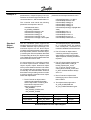
Operating Instructions
www.danfoss.com/drives
LonWorks FTP
VLT® 5000
VLT® 6000 HVAC
VLT® 8000 AQUA
175R0948
MG60N202
*MG60N202*
Rev. 2004-03-11
LonWorks® FTP Option Card
Instruction Manual
VLT® 5000 / VLT® 6000 HVAC / VLT® 8000 AQUA
! DANGER
Rotating shafts and electrical equipment can
be hazardous. Therefore, it is strongly
recommended that all electrical work conform
to the National Electrical Code (NEC) and all
local regulations. Installation, start-up and
maintenance should be performed only by
qualified personnel.
Factory recommended procedures, included in this manual,
should be followed. Always disconnect electrical power before
working on the unit.
Although shaft couplings or belt drives are generally not
furnished by the manufacturer, rotating shafts, couplings and
belts must be protected with securely mounted metal guards
that are of sufficient thickness to provide protection against
flying particles such as keys, bolts and coupling parts. Even
when the motor is stopped, it should be considered “alive”
as long as its controller is energized. Automatic circuits may
start the motor at any time. Keep hands away from the output
shaft until the motor has completely stopped and power is
disconnected from the controller.
Motor control equipment and electronic controls are
connected to hazardous line voltages. When servicing drives
and electronic controls, there will be exposed components
at or above line potential. Extreme care should be taken to
protect against shock. Stand on an insulating pad and make
it a habit to use only one hand when checking components.
Always work with another person in case of an emergency.
Disconnect power whenever possible to check controls or
to perform maintenance. Be sure equipment is properly
grounded. Wear safety glasses whenever working on electric
control or rotating equipment.
does not disconnect the equipment from the AC line and
is not to be used as a safety switch.
3. Correct protective grounding of the equipment must be
established. The user must be protected against supply
voltage and the motor must be protected against
overload in accordance with applicable national and local
regulations.
4. Ground currents are higher than 3 mA.
Warnings Against Unintended
Start
1. While the drive is connected to the AC line, the motor
can be brought to a stop by means of external switch
closures, serial bus commands or references. If personal
safety considerations make it necessary to ensure that
no unintended start occurs, these stops are not sufficient.
2. During programming of parameters, the motor may start.
Be certain that no one is in the area of the motor or
driven equipment when changing parameters.
3. A motor that has been stopped may start unexpectedly
if faults occur in the electronics of the drive, or if an
overload, a fault in the supply AC line or a fault in the
motor connection or other fault clears.
4. If the “Local/Hand” key is activated, the motor can only
be brought to a stop by means of the “Stop/Off” key or
an external safety interlock.
NOTE:
It is responsibility of user or person installing
drive to provide proper grounding and branch
circuit protection for incoming power and
motor overload according to National Electrical
Code (NEC) and local codes.
The Electronic Thermal Relay (ETR) is UL listed.VLTs provide
Class 20 motor overload protection in accordance with the
NEC in single motor applications, when VLT 6000/8000
parameter 117 (VLT 5000 parameter 128) is set for ETR Trip 1
1. The drive must be disconnected from the AC line before
and parameter 105 is set for rated motor (nameplate) current.
any service work is done.
2. The “Stop/Off” key on the local control panel of the drive
Safety Guidelines
! DANGER
Touching electrical parts may be fatal – even after equipment has been
disconnected from AC line. To be sure that capacitors have fully discharged, wait 14 minutes after power has been removed before touching
any internal component.
2
MG.60.N2.02 - VLT is a registered Danfoss trademark
VLT® 5000 / VLT® 6000 HVAC / VLT® 8000 AQUA
Table of Contents
Overview
Introduction .............................................................................................
About This Manual ..................................................................................
Assumptions ...........................................................................................
What You Should Already Know ............................................................
References ..............................................................................................
LonWorks Overview ................................................................................
LON Concept ...........................................................................................
Applications ............................................................................................
VLT LonWorks Option Card ....................................................................
Node Arrangements ................................................................................
Message Passing ....................................................................................
Collision Detection .................................................................................
Network Management .............................................................................
Routers and Bridges ...............................................................................
5
5
5
5
5
6
6
6
7
7
7
8
8
9
Installation
Wiring Installation ................................................................................... 10
Card Installation ...................................................................................... 10
Tools Required ........................................................................................ 10
VLT LonWorks Option Card.......................................................................11
Installation Instructions ......................................................................... 12
Network Initialization of LonWorks Option Card ................................... 19
Resource files .......................................................................................... 19
Free Topology Network Configuration
Free Topology Network Configuration ..................................................
Network Termination Option ..................................................................
Terminator and Service Switch Locations ............................................
System Performance ..............................................................................
System Specifications ............................................................................
Transmission Specifications ..................................................................
Free Topology Specifications .................................................................
Doubly-terminated Bus Topology Specifications .................................
20
21
21
22
22
22
22
22
Diagnostic LEDs
LonWorks Card Diagnostic LEDs ...........................................................
Status LED ...............................................................................................
Service LED .............................................................................................
Service LED Patterns and Descriptions .................................................
MG.60.N2.02 - VLT is a registered Danfoss trademark
23
23
23
24
3
VLT® 5000 / VLT® 6000 HVAC / VLT® 8000 AQUA
Interface/Network Variables
VLT Adjustable Frequency Drive
and LonWorks Network Configuration ...................................................
Network Drive Control Input ...................................................................
Drive Feedback to Network .....................................................................
Drive Status Bit Definitions .....................................................................
Network Timer Functions .......................................................................
VLT Parameter Access ............................................................................
Parameter Access Error Codes ...............................................................
Parameter Access Command and Response Examples ........................
Standard Object Support ........................................................................
Alarm Descriptions ..................................................................................
25
26
29
31
33
34
35
35
37
38
Parameters
Parameter List ......................................................................................... 39
Parameter Description ............................................................................. 39
4
MG.60.N2.02 - VLT is a registered Danfoss trademark
VLT® 5000 / VLT® 6000 HVAC / VLT® 8000 AQUA
Introduction
About This
Manual
This manual provides comprehensive
instructions on the installation and set up of
the LonWorks Option Card for the VLT 5000,
VLT 6000 and the VLT 8000 Adjustable
Frequency Drive to communicate over a
LonWorks network.
Operation and Instruction Manual or VLT8000
Installation, Operation and Instruction Manual.
Portions of this manual are printed with the
permission of the Echelon Corporation and the
National Electrical Contractors Association of
the USA (NECA).
For specific information on installation and
operation of the adjustable frequency drive,
refer to the VLT 5000 Installation, Operation
and Instruction Manual , VLT 6000 Installation,
Echelon®, LonTalk®, Neuron® and LonWorks®
are registered trademarks of the Echelon
Corporation. VLT® is a registered trademark
of Danfoss Inc.
This manual is intended to be used for both
instruction and reference. It only briefly
touches on the basics of the LonWorks
protocol whenever it is necessary for gaining
an understanding of the LonWorks profile for
drives and the LonWorks Option Card for the
Adjustable frequency drive.
communication system. Even if you are an
experienced LonWorks programmer, we
suggest that you read this manual in its entirety
before you start programming, since important
information can be found in all sections.
This manual is also intended to serve as a
guideline when you specify and optimize your
Assumptions
This manual assumes that you have a
controller node that supports the interfaces
in this document and that all the requirements
stipulated in the controller node, as well as
the Adjustable Frequency Drive, are strictly
observed along with all limitations therein.
What You
Should
Already Know
The Danfoss LonWorks Option Card is
designed to communicate with any controller
node that supports the interfaces defined in
this document. It is assumed that you have
full knowledge of the capabilities and
limitations of the controller node.
References
LonMaker™ for Windows® User's Guide.
VLT ® 5000 Installation, Operation and
Instruction Manual
(Referred to as the VLT Instruction Manual in
this document.)
VLT ® 8000 Installation, Operation and Instruction
Manual
(Referred to as the VLT Instruction Manual in
this document.)
VLT ® 6000 Installation, Operation and
Instruction Manual
(Referred to as the VLT Instruction Manual in
this document.)
MG.60.N2.02 - VLT is a registered Danfoss trademark
5
VLT® 5000 / VLT® 6000 HVAC / VLT® 8000 AQUA
LonWorks
Overview
LonWorks is both an existing standard and
hardware developed by Echelon Corporation.
Echelon's stated goal is to establish a commodity solution to the presently daunting
problems of designing and building control
networks.
The result is LonMark Interoperability which
makes it possible for independent network
devices to operate together over a
LonWorks network. The LonMark program
was developed to address interoperability
issues. As a result, the LonMark
Interoperability Association Task Groups
(LonUsers Groups) were developed. The
task groups determine that each device on
the network has an object definition, create
LON
Concept
The LonWorks communications structure is
similar to that of a local area network (LAN)
in that messages are continually exchanged
between a number of processors. A
LonWorks system is a determined local
operating network (LON). LON technology
offers a means for integrating various
distributed systems that perform sensing,
monitoring, control, and other automated
functions. A LON allows these intelligent
devices to communicate with one another
through an assortment of communications
media using a standard protocol.
standards and models to be used by
particular applications and create a common
platform for presenting data. A standard
network variable type (SNVT) facilitates
interoperability by providing a well defined
interface for communication between
devices made by different manufacturers.
The VLT Adjustable Frequency Drive
supports the node object and controller
standard object definitions of LonMark
Interoperability.
Customers are currently using LonWorks for
process control, building automation, motor
control, elevator operation, life safety
systems, power and HVAC distribution and
similar intelligent building applications.
network devices can communicate directly
with one another without need for a central
control system. A LON is designed to move
sense and control messages which are
typically very short and which contain
commands and status information that
trigger actions. LON performance is viewed
in terms of transactions completed per
second and response time. Control systems
do not need vast amounts of data, but they
do demand that the messages they send
and receive are absolutely correct. The critical
factor in LON technology is the assurance
of correct signal transmission and verification.
LON technology supports distributed, peerto-peer communications. That is, individual
Applications
An important LonWorks benefit is the
network’s ability to communicate across
different types of transmission media. The
NEURON chip is the heart of the LonWorks
system. The N EURON chip's communication port allows for the use of
transceivers for other media (such as coax
and fiber optic) to meet special needs.
LonWorks control devices are called nodes.
Physically, each node consists of a NEURON
chip and a transceiver. With proper design,
the nodes become building blocks that can
6
be applied to control a variety of tasks, such
as lighting or ventilating, integrating a variety
of communications media.
The tasks which the nodes perform are
determined by how they have been
connected and configured. Because
hardware design, software design, and
network design may be independent in a
LonWorks-based system, a node’s function
can be programmed to accommodate the
networks in which it will be used.
MG.60.N2.02 - VLT is a registered Danfoss trademark
VLT® 5000 / VLT® 6000 HVAC / VLT® 8000 AQUA
VLT LonWorks The Danfoss VLT LonWorks option card is
comprised of a control card with a NEURON
Option Card
chip and a memory card. When installed into
the VLT adjustable frequency drive, the unit
enables the drive to communicate with other
devices on the LON.The VLT drive is designed
to provide precision control of standard
induction electrical motors. The drive receives
three reference signals along with start/stop
and reset commands from the network. The
drive also receives a 16-bit control word that
provides full operational control of the drive.
(See Network Drive Control Input for additional
details.)
In response, the drive provides 16 output
network variables containing important drive
and motor data. (See Drive Feedback to
Network.) Output to the network includes
drive status, current, voltage, motor and
inverter thermal status, and alarms and
warnings.
Node
Arrangements
LonWorks nodes can be addressed either
individually or in groups. A group can contain
up to 64 nodes, and one LonWorks network
can support 255 groups. Furthermore, any
node can be part of 15 different groups. A
subnet, very similar to a group, can contain
127 nodes. A domain is the largest
arrangement of nodes with a single domain
able to handle 255 subnets. Thus a domain
can handle 32,385 separate nodes. A single
node may be connected to no more than two
domains.
The group structure has the advantage of
allowing a number of nodes to be reached at
only one address. This method reduces the
Message
Passing
There are a number of trade-offs between
network efficiency, response time, security,
and reliability. Generally, LonWorks defaults to
the greatest degree of safety and verification
for all communications over the LON network.
The LonTalk protocol, built into the chips, is
the operating system that coordinates the
LonWorks system. It offers four basic types
of message service.
MG.60.N2.02 - VLT is a registered Danfoss trademark
LonWorks supports many different types of
transmission media. A LonWorks network
physical layer option can be transformer
coupled twisted pair (78 kbps and 1.25
Mbps), free topology, link power, power line,
RF, RS-485, fiber optic, coaxial, or infrared.
The VLT LonWorks option supports four
transmission media with three versions of the
VLT LonWorks option card. The VLT
LonWorks option card versions are:
1. Free topology, which also operates on
a link power network.
2. 78 kbps transformer coupled twisted
pair.
3. 1.25 Mbps transformer coupled twisted
pair.
A router is required to interface to a LonWorks
network when not supported by one of the
three option card versions.
record keeping inside each chip to a minimum,
allowing faster operation. However, high
efficiency individual addressing can be done
at all levels of a LonWorks system. The
address table of a node contains entries for
the group type and size and tells the node
how many acknowledgments to expect when
it sends a message. It also tells the NEURON
chip which domain to use and the node group
member number, which identifies an
acknowledgment as coming from the node.
The address also contains a transmit timer, a
repeat timer, a retry counter, a receive timer,
and the group ID.
The most reliable service is acknowledged (or
end-to-end acknowledged service), where a
message is sent to a node or group of nodes
and individual acknowledgments are expected from each receiver. If an
acknowledgment is not received from all destinations, the sender times out and re-tries
the transaction. The number of retries and
time-out duration are both selectable. Ac-
7
VLT® 5000 / VLT® 6000 HVAC / VLT® 8000 AQUA
Message
Passing
(continued)
knowledgments are generated by the network
host processor without intervention of the application. Transaction IDs are used to keep
track of messages and acknowledgments so
that the application does not receive duplicate messages.
An equally reliable service is request/response,
where a message is sent to a node or group
of nodes and individual responses are expected from each receiver. Incoming
messages are processed by the application
on the receiving side before a response is
generated. The same retry and time-out options are available as with acknowledged
service. Responses may include data, so that
this service is particularly suitable for remote
procedure call or client/server applications.
Next in reliability is unacknowledged repeated.
Messages are sent multiple times to a node
or a group of nodes with no response
expected. This service is typically used when
broadcasting to large groups of nodes when
traffic generated by all the responses would
overload the network.
The final method in reliability is unacknowledged, where a message is sent once
to a node or group of nodes and no response
is expected. This option is typically used when
the highest performance is required, network
bandwidth is limited, and the application is
not sensitive to the loss of a message.
Collision
Detection
The LonTalk protocol uses a unique collision
avoidance algorithm which allows an
overloaded channel to carry near to its
maximum capacity, rather than reducing its
throughput due to excessive collisions
between messages. When using a
communications medium that supports
collision detection, such as twisted pair, the
LonTalk protocol can optionally cancel
transmission of a packet as soon as a collision
is detected by the transceiver. This option
allows the node to immediately retransmit any
packet that has been damaged by a collision.
Without collision detection, the node would
wait the duration of the retry time to notice
that no acknowledgment was received. At that
time it would retransmit the packet, assuming
acknowledge or request/response service.
For unacknowledged service, an undetected
collision means that the packet is not received
and no retry is attempted.
Network
Management
Depending on the level of a given application,
a LonWorks network may or may not require
the use of a network management node. A
network management node performs
management functions, such as:
• Find unconfigured nodes and
download their network addresses.
• Stop, star t, and reset node
applications.
• Access node communication statistics.
• Configure routers and bridges.
• Download new applications programs.
• Extract the topology of a running
network.
8
MG.60.N2.02 - VLT is a registered Danfoss trademark
VLT® 5000 / VLT® 6000 HVAC / VLT® 8000 AQUA
Routers and
Bridges
A router (or bridge) is a special node that
consists of two connected NEURON chips, each
connected to a separate channel (see figure
below). Routers and bridges pass packets
back and forth between these channels. There
are four types of routers. A repeater is the
simplest form of router, simply forwarding all
packets between the two channels. A bridge
simply forwards all packets which match its
domains between the two channels. Using a
bridge or repeater, a subnet can exist across
multiple channels. A learning router monitors
the network traffic and learns the network
topology at the domain/subnet level. The
learning router then uses its knowledge to
selectively route packets between channels.
Like a learning router, a configured router
selectively routes packets between channels
by consulting internal routing tables. Unlike a
learning router, the contents of the internal
routing tables are specified using network
management commands.
Initially, each router sets its internal routing tables
to indicate that all subnets could lie on either side
of the router. Suppose that node 6, in the figure
below, generates a message bound for node 2.
Learning router 1 initially picks up the message.
It examines the source subnet field of the
message and notes in its internal routing tables
that subnet 2 lies below it. The router then
compares the source and destination subnet IDs
and, since they are different, the message is
passed on. Meanwhile, learning router 2 also
passes the message on, making an appropriate
notation in its internal routing tables regarding the
location of subnet 2.
Suppose now that node 2 generates an
acknowledgment. This acknowledgment is
picked up by learning router 1, which now notes
the location of subnet 1. Learning router 1
examines its internal routing tables, and, noting
that subnet 2 lies below, passes the message
on. When the message appears on subnet 2, it
is noted by both node 6 (the destination) and
learning router 2. Learning router 2 does not pass
it on but merely notes that subnet 1, like subnet
2, lies somewhere above. Learning router 2 will
not learn of the existence or location of subnet 3
until a message is originated from there. Subnets
cannot cross routers. While bridges and
repeaters allow subnets to span multiple
channels, the two sides of a router must belong
to separate subnets. Since routers are selective
about the packets they forward to each channel,
the total capacity of a system can be increased
in terms of nodes and connections.
Channel
1
2
3
4
R
Learning
Router 1
Channel
Subnet 1
Learning
Router 2
R
5
6
7
8
Channel
Subnet 2
9
10
11
12
Subnet 3
Learning Routers
Source: Echelon Corp.
MG.60.N2.02 - VLT is a registered Danfoss trademark
9
VLT® 5000 / VLT® 6000 HVAC / VLT® 8000 AQUA
Wiring
Installation
Wiring
The adjustable frequency drive generates a
carrier frequency with a pulse frequency
between 3 kHz and 14 kHz. This results in
radiated frequency noise from the motor
cables. It is very important that the LonWorks
cable be isolated as much as possible from
the drive output cabling to the motor. Use
shielded wire rather than twisted-pair. Do not
run LonWorks cabling and motor cables in
parallel or in close proximity to one another.
Ensure that the drive is properly grounded.
Card
Installation
The following section describes the installation
procedures for the LonWorks option card (see
following illustration). For additional information
on installation and operation of the VLT
adjustable frequency drive, refer to the VLT
Instruction Manual.
! DANGER
VLT adjustable frequency drive
contains dangerous voltages
when connected to line power.
After disconnecting from line,
wait at least 14 minutes before
touching any electrical components.
! WARNING
Only a competent electrician
should carry out electrical
installation. Improper installation
of motor or VLT can cause
equipment failure, serious injury
or death. Follow this manual,
National Electrical Code (USA)
and local safety codes.
Tools
Required
10
! CAUTION
Electronic components of VLT
adjustable frequency drives are
sensitive to electrostatic discharge (ESD). ESD can reduce
performance or destroy sensitive
electronic components. Follow
proper ESD procedures during
installation or servicing to
prevent damage.
! CAUTION
It is responsibility of user or
installer of VLT adjustable
frequency drive to provide proper
grounding and motor overload
and branch protection according
to National Electrical Code (USA)
and local codes.
Flat-head screw driver
Torx T-10 screw driver
Torx T-20 screw driver
MG.60.N2.02 - VLT is a registered Danfoss trademark
VLT® 5000 / VLT® 6000 HVAC / VLT® 8000 AQUA
LEDs
Service Pin
Switch SW1
Terminal
Connector
Terminator
Switch
Mounting Hole
LEDs
Host
Chip
Terminal
Connector
Ribbon
Cable
Socket
(to Memory
Board)
Service Pin
Switch SW3
Ribbon
Cable
Socket
(to Control
Board)
LonWorks Control Board
Drive
Memory
Ribbon
Cable
Socket
(to drive
control
board)
Memory Board
VLT LonWorks Option Card
(Free Topology Model)
MG.60.N2.02 - VLT is a registered Danfoss trademark
11
VLT® 5000 / VLT® 6000 HVAC / VLT® 8000 AQUA
Installation Instructions
1. Access to
Control
Card
Cassette
IP20/NEMA 1 and Bookstyle
• Remove Local Control Panel (LCP) by
pulling out from top of display (A) by
hand. LCP connector on panel back
will disconnect.
• Remove protective cover by gently
prying with a screw driver at notch (B)
and lift cover out of guide pin fittings.
(A)
(B)
IP54/NEMA 12
Open front panel of drive by loosening
captive screws and swing open.
• Disconnect Local Control Panel (LCP)
cable from drive control card.
•
(A)
2. Disconnect
Control
Card
Cassette
•
•
•
Remove control wiring by unplugging
connector terminals (A).
Remove grounding clamps (B) by
removing two screws holding each in
place. Save screws for reassembly.
Loosen two captive screws (C) securing
cassette to chassis.
(B)
(C)
12
MG.60.N2.02 - VLT is a registered Danfoss trademark
VLT® 5000 / VLT® 6000 HVAC / VLT® 8000 AQUA
3. Remove
Cassette
and Ribbon
Cables
•
•
•
Lift control card cassette from bottom.
Unplug two ribbon cables (A) and (B)
from control board.
Unhinge cassette at top to remove.
(A)
(B)
NOTE
Ribbon cables will need to be
reconnected to same connections from which removed.
4. Chassis
Ground
Connections
NOTE
Ground strips are used on 208 V
drives of 22 kW (30 HP) or less
and on 460 V drives of 45 kW
(60 HP) or less. For all other
drives, go to step 6.
•
Location of holes to mount grounding
strips can vary with drive configuration.
When applicable, remove mounting
screws and washers located in chassis
using Torx T-20 screw driver and save
for reassembly. Otherwise, grounding
strips attach with screws and washers
provided, as shown in step 5.
MG.60.N2.02 - VLT is a registered Danfoss trademark
13
VLT® 5000 / VLT® 6000 HVAC / VLT® 8000 AQUA
5. Install
Chassis
Ground
Connections
• Align ground strips over screw holes.
Strip with fewest contact points mounts
on cable side of chassis. Tabs on
grounding strips point toward outside
of chassis.
• Replace screws removed in step 4 and
add additional screws and washers
provided, as necessary. Tighten to
0.9 Nm (8 in-lbs) using Torx T-20 screw
driver.
Ground
Strips
6. Install
Ribbon
Cables
between
Option
Cards
• Attach ribbon cables between
LonWorks control card and memory
card.
• Be sure exposed wire portion of ribbon
cable (A) is facing front of socket (B).
Do not remove blue insulation covering
end of ribbon cable.
• Pull up collar (C) of ribbon cable socket,
insert cable and push collar closed.
• Repeat procedure for all ribbon cables.
(D)
(E)
IP20/NEMA 1 and IP54/NEMA 12
• Remove terminal connector from
terminal block (D) and connect to
terminal block (E) at this time for ease
of access.
14
MG.60.N2.02 - VLT is a registered Danfoss trademark
VLT® 5000 / VLT® 6000 HVAC / VLT® 8000 AQUA
IP20/NEMA 1 and Bookstyle
Carefully push in tabs at corners of LCP
cradle to release clips. Pull out to
disengage clips and lift cradle free.
7. Remove
LCP Cradle
•
8. Ribbon
Cable
Routing
• Route ribbon cables from LonWorks
memory card through slot at side of
control board cassette.
9. Insert
LonWorks
Card
• Insert edge of LonWorks cards into slot
in side of cassette and align screw
holes.
MG.60.N2.02 - VLT is a registered Danfoss trademark
15
VLT® 5000 / VLT® 6000 HVAC / VLT® 8000 AQUA
10. Secure
LonWorks
Card
•
Secure LonWorks card with 3
self-tapping screws and washers
provided using Torx T-10 screw driver.
Tighten to 8 in-lbs (0.9 Nm).
11. Install
Ribbon
Cable on
VLT Control
Board
•
Be sure not to twist or crimp ribbon
cables.
Insert cables into corresponding
sockets and fasten in accordance with
directions in step 5.
12. Install
LCP Cradle
IP20/NEMA 1 and Bookstyle
• Insert cradle clips into holes in cassette.
• Push down on cradle to snap it into
place.
16
•
MG.60.N2.02 - VLT is a registered Danfoss trademark
VLT® 5000 / VLT® 6000 HVAC / VLT® 8000 AQUA
13. Install
Spring
Tension
Clip
IP20/NEMA 1 and IP54/NEMA 12
Spring tension clip (A) is used as a cable
strain relief and ground point for
shielded cable.
• Insert clip through inner wall of chassis
at slot provided.
• Compress spring into clip at outer wall
of chassis.
•
(A)
14. Install
Ribbon
Cables
•
•
Connect ribbon cables.
Connect control card cassette to hinge
at top of drive and fit into chassis.
NOTE
Ribbon cables must be reconnected to same connections from
which removed.
MG.60.N2.02 - VLT is a registered Danfoss trademark
17
VLT® 5000 / VLT® 6000 HVAC / VLT® 8000 AQUA
•
•
•
16. Plug in
Terminal
Connector
•
(C)
Fasten control card cassette by
alternately tightening two captive
screws (A). Tighten to 0.9 Nm (8 in-lbs).
Route control wires through clamp
fasteners (B) and secure clamps with
two screws.
Connect control terminals (C) by firmly
pressing them into connector
receptacles.
(A)
(B)
Connect signal wire NET A to terminal
79 and NET B to 80 of terminal
connector. (In free topology model,
connections can be reversed.)
79 80 61
15. Install
Control Card
Cassette
IP20/NEMA 1 and IP54/NEMA 12
Plug network connector into terminal
block at side of control card cassette.
• Insert LonWorks cable between inner
wall of chassis and spring tension clip.
•
Shield 61
NET B 80
NET A 79
NOTE
Shielded cable is recommended.
Ground shielded cable at spring
tension clip location or ground at
cable clamp by removing cable
insulation at contact point. Do not
use connector terminal 61.
Bookstyle
Remove knockout from top of drive (A).
Route control wires through clamp
fasteners (B) on cable plate and secure
clamps with screws. Tighten to 0.9 Nm
(8 in-lbs).
• Secure cable plate to drive with screws
and screw holes provided. Tighten to
0.9 Nm (8 in-lbs).
• Plug network connector (C) into
terminal block at top of control card
cassette.
•
•
18
(B)
(C)
(A)
MG.60.N2.02 - VLT is a registered Danfoss trademark
VLT® 5000 / VLT® 6000 HVAC / VLT® 8000 AQUA
Network
Initialization
of LonWorks
Option Card
The LonWorks option card contains a NEURON
chip with a unique address. After hardware
installation, initialize the LonWorks option card.
Addressing nodes on the LonWorks network
is performed at installation time by an
installation tool or network management tool.
Addressing requires the retrieval of a node’s
NEURON ID. The NEURON ID is a 48 bit number
that identifies every manufactured NEURON
chip. There are several methods by which the
network software will initialize the drive
automatically. The network can recognize the
drive without action beyond proper
installation. The card is then ready to be
programmed for network operation. The VLT
LonWorks option supports three additional
methods of addressing a node:
1. Service Pin - There are two
momentary-contact service switches that
send the NEURON ID over the network. If the
network software prompts the action, press
Resource
files
A LonMark interface file (.XIF extension)
provides the host processor with device
information. With this, it is possible to design a
LonWorks network without the adjustable
frequency drive being physically present.
The resource files (VLTLON.XIF and
DanfossVSD_03.*) can be downloaded from
the Internet site www.danfoss.com/drives.
Echelon Corporation has also developed a set
of free plug-ins available through their web site
at www.echelon.com/plugin/default.htm. Also
intended for network design, these plug-ins
provide easy access to screens which simplify
the process of manually setting up the drive,
testing, and monitoring operation.
MG.60.N2.02 - VLT is a registered Danfoss trademark
either service pin (SW1 or SW3) to transmit
the NEURON ID over the network. The service
pin locations are shown in the illustration in
Terminator and Service Switch Locations in
this manual.
2. Query and Wink - The LonWorks option
card is shipped with a domain of “0” and
subnet of “1.” Upon receiving the wink
command, the on-board green status LED
flashes so that the installer can locate the
node. The chip sends out its Neuron ID over
the network in response to the query
command.
3. NEURON ID Label - The VLT LonWorks
option card has a N EURON ID label that
displays the N EURON ID as a 12 digit
hexadecimal number. The installer can
manually enter the N EURON ID during
installation.
The drive may also be added to the network
upon initialization.
The VLT LonWorks network interface
consists of SNVTs and SCPT. The SNVTs
support the LonMark Controller Profile along
with VLT configuration, control and monitoring capabilities. Any combination of SNVTs
can be used to operate the VLT.
We also support the Functional Profile for
Variable Speed Drives version 1.1 from the
LonMark organisation.This profile defines a
set of Network variables (SNVT) and
configuration properties (SCPT).
19
VLT® 5000 / VLT® 6000 HVAC / VLT® 8000 AQUA
Free
Topology
Network
Configuration
The Free Topology Transceiver (FTT) system
is designed to support free topology wiring
and accommodates bus, star, loop or any
combination of these topologies. The FTT
transceiver located on the VLT LonWorks
option card provides I/O functions. Flexible
wiring capability simplifies system installation
and makes it easy to add nodes for system
expansion. The figures below represent five
network topologies.
Singly Terminated
Bus Loop
TERMINATION
Doubly Terminated
Bus Loop
TERMINATION
TERMINATION
Star Topology
TERMINATION
Loop Topology
Mixed
Topology
TERMINATION
Loop
MixedTopology
Topology
TERMINATION
20
MG.60.N2.02 - VLT is a registered Danfoss trademark
VLT® 5000 / VLT® 6000 HVAC / VLT® 8000 AQUA
Network
Termination
Option
The option of using termination on the
LonWorks card is provided. The option card
has a termination resistor built-in which is
activated by the terminator switches. Use of
the terminator is optional, depending upon the
network configuration. If termination is
provided elsewhere in the network, the
termination function should be OFF.
Terminator switches position functions are
provided in the table below.
Switch Position Functions
Pos 1
Pos 2
No termination
Net Term OFF
Net Term OFF
(Factory setting)
(Factory setting)
Single termination
Net Term ON
Net Term OFF
Double termination
Net Term ON
Net Term ON
Service Pin Switch
Terminator Switches
1
OFF
Terminator
and Service
Switch
Locations
Termination
2
Service Pin Switch
Free Topology LonWorks Control Card
MG.60.N2.02 - VLT is a registered Danfoss trademark
21
VLT® 5000 / VLT® 6000 HVAC / VLT® 8000 AQUA
System
Performance
Free topology system specifications and
transmission specifications are described
below. Both specifications should be met to
ensure proper operation.
The system designer may choose from a
variety of cables, depending on cost,
availability, and desired performance.
Performance may vary with cable type.
Contact Echelon for cable types and the
characterization of system performance.
The transmission specification depends on
such factors as resistance, mutual
capacitance and the velocity of propagation.
System
Specifications
•
•
Note that the following specifications are for one
network segment. Multiple segments may be
combined using repeaters to increase the
number of nodes and distance.
• The average temperature of the wire
must not exceed 55° C (131° F),
although individual segments of wire
may be as hot as 85° C (185° F).
Up to 64 FTT-10 transceivers, or 128
LPT-10 transceivers, are allowed per
network segment.
Both types of transceivers may be
used on a given segment, provided
that the following constraint is met:
(2 x number of FTT-10 transceivers) +
(number of LPT-10 transceivers)
≤128.
Transmission
Specifications
Free Topology nodes run at 78 kbps
transmission speeds.
Cable
Specifications
Danfoss recommends the use of shielded LonWorks
communication cable for instance Belden 8719. See
also section 12 Plug in terminal Connector.
Free
Topology
Specifications
DoublyTerminated
Bus
Topology
Specifications
22
Maximum
node-to-node distance
Maximum
total wire length
Belden 85102
500 m / 1640 ft
500 m / 1640 ft
Belden 8471
400 m / 1312 ft
500 m / 1640 ft
Level IV, 22AWG
400 m / 1312 ft
500 m / 1640 ft
JY (St) Y 2x2x0.8
320 m / 1050 ft
500 m / 1640 ft
Maximum bus length for
segments with
FTT-10 transceivers only
Maximum bus length for
segments with both FTT-10
and LPT-10 transceivers
Belden 85102
2700 m / 8858 ft
2200 m / 7217 ft
Belden 8471
2700 m/ 8858 ft
2200 m / 7217 ft
Level IV, 22AWG
1400 m / 4593 ft
1150 m / 3772 ft
JY (St) Y 2x2x0.8
900 m / 2952 ft
750 m / 2460 ft
MG.60.N2.02 - VLT is a registered Danfoss trademark
VLT® 5000 / VLT® 6000 HVAC / VLT® 8000 AQUA
LonWorks
Card
Diagnostic
LEDs
The LonWorks board includes two LEDs to
display the communication status of the
board, display the state of the NEURON chip,
and respond to the network management
Status LED
The Status LED patterns are:
“wink” command. The onboard LEDs are the
Service LED (LED 1, red) and the Status LED
(LED 2, green).
LEDs
ON
There is power on the board but
there has not been any
communication to an input network
variable in the last 2 seconds.
Flashing 10 times per second
There is regular network
communication to the VLT's input
network variables.
Flashing intermittently
There is network communication to
the VLT's input network variables but
input network variables are received
at a period greater than 2 seconds.
Flashing 5 times per second
The response to the network
management “Wink” command. The
VLT LonWorks node must be reset to
leave the wink state.
OFF
No power on board or hardware fault.
Service LED
The Service LED displays the state of the
NEURON chip. The following table shows the
Service LED patterns for various states and
defines their meaning.
MG.60.N2.02 - VLT is a registered Danfoss trademark
23
VLT® 5000 / VLT® 6000 HVAC / VLT® 8000 AQUA
Service LED
Patterns and
Descriptions
LED Pattern
Continuously ON
Operation
Power-up of Neuron 3120xx
chip-based node or Neuron
3150 chip-based node with
any PROM
Description
Use EEBLANK and follow
reinitialization procedure.
Continuously OFF
Power-up of Neuron 3120xx
chip-based node or Neuron
3150 chip-based node with
any PROM
Indicates bad node hardware.
ON for one second at power-up Power-up/Reset
followed by approximately 2
seconds OFF, then stays ON
May be caused by Neuron chip
firmware when mismatch occurs
in application checksum.
Short flash every 3 seconds
Indicates watchdog timer resets
occurring.
Anytime
Possible corrupt EEPROM.
For Neuron 3150 chip-based
node, use EEBLANK and follow
reinitialization procedure.
Flashing at 1 second intervals
Anytime
Indicates node is unconfigured
but has an application. Proceed
with loading node.
Brief flash at power-up. OFF
duration approximately 10
seconds after which stays ON
Using EEBLANK or Neuron
3150 chip-based node
Indicate completion of blanking
process.
Brief flash at power-up. OFF
duration approximately 1 to 15
seconds, depending on
application size and system
clock. LED then begins flashing
at 1 second intervals.
Indicates unconfigured state.
First power-up with new
PROM on Neuron 3150 chipbased custom node.
Unconfigured firmware state
exported.
Brief flash at power-up followed
by OFF
Node is configuring and running
normally.
Service LED Pattern Descriptions
24
MG.60.N2.02 - VLT is a registered Danfoss trademark
VLT® 5000 / VLT® 6000 HVAC / VLT® 8000 AQUA
Configurations
properties
(Nci)
The VLT LonWorks option card supports
LonMark network design to improve
interoperability. The Controller Object
contains the VLT Adjustable Frequency
Drive profile.
Function
Nom. motor freq. 1)
Nom. motor rpm
Min. frequency
1)
1)
Max. frequency 1)
Ramp up time 1
1)
Ramp down time 1
Heart beat time
1)
1)
The configuration parameters are network
variable inputs to the VLT. Configuration of
parameters needs setting only one time,
usually at installation.
SNVT type
Variable Name
Units
VLT 6000/8000
parameter
VLT 5000
parameter
SNVT_freq_hz
nciNmlFreq
1 Hz
104
104
SNVT_rpm
nciNmlSpeed
1 rpm
106
106
SNVT_lev_percent
nciMinSpeed
0.005%
201
201
SNVT_lev_percent
nciMaxSpeed
0.005%
202
202
SNVT_time_sec
NciRampUpTime
1 sec
206
207
SNVT_time_sec
NciRampDownTime
1 sec
207
208
SNVT_time_sec
NciSndHrtBt
0.1 sec
-
-
(EDIT SETUP SELECT)
Part of the LonMark Functional Profile for
Variable Speed Drive 6010 version 1.1
1)
When the NciSndHrtBt time is active it will sent
the following variables:
• nvoDrvCurnt
• nvoDrvSpeed
• nvoDrvVolt
• nvoDrvPwr
NOTE
Please note that writing to Configuration
properties will be stored in the Non-Volatile
memory.
Continous writing to Configuration properties
may damage the Non-Volatile memory.
Please note that nciNmlFreq and nciNmlSpeed
can only be written to when the VLT frequency
converter is stopped.
VLT 5000 parameters are shown in parenthesis, where applicable.
MG.60.N2.02 - VLT is a registered Danfoss trademark
25
VLT® 5000 / VLT® 6000 HVAC / VLT® 8000 AQUA
Network
Drive
Control
Input
The most common functions for controlling the
VLT Adjustable Frequency Drive from the
LonWorks network are made readily available.
Those functions and their descriptions are
presented in the table below. The control word
function accesses additional drive capabilities
for network control.
All references provided to the drive are added
to the total reference value. If reference is to
be controlled by the LonWorks bus only, ensure
that all other reference inputs are zero. This
means that digital input terminals and analog
input terminals should not be used for reference
signals. The default setting (0%) should be
maintained for preset references in parameters
211 (215) through 214 (218). Also, in closed
loop operation, the default setting (0.0) should
be maintained for drive setpoints in parameters
418 (215) and 419 (218).
The choice of open loop or closed loop
operation of the drive is selected in parameter
100, Configuration.
Using nviRefPcnt, the drive's reference is
expressed as a percentage of the reference
range. The range is set using parameters 204,
Min. Reference and 205, Max. Reference. In
open loop operation, reference represents the
drive's desired output speed. In this case, set
Min. Reference to 0 Hz and Max. Reference
equal to Max. Frequency in parameter 202.
Start/Stop and Reset fault
SNVT_lev_disc. ST_OFF and ST_NUL are
interpreted as low or “0.” ST_LOW, ST_MED,
ST_HIGH, and ST_ON are interpreted as high
or “1.”
NOTE
To optimize network performance
and for proper drive operation,
use only one of following input
reference commands.
In closed loop operation, reference represents
the desired setpoint. It is recommended that
parameters 204 and 205 be set equal to
parameters 201, Min. Frequency and 202,
Max. Frequency.
Reference 1
Network variable nviRefPcnt is a signed value.
It represents the desired percentage of the
VLT drive's reference range.
Range: -163.840 - 163.835.
Function
SNVT type
Variable Name
Units
Start/Stop
SNVT_lev_disc
nviStartStop
Boolean
104
*Reset fault
SNVT_lev_disc
nviResetFault
Boolean
-
-
Reference 1
SNVT_lev_percent nviRefPcnt
0.005%
-
-
Reference 3
SNVT_freq_hz
nviRefHz
0.1 Hz
-
-
SNVT_state
nviControlword
16 Boolean
-
-
Drive Speed Setpoint
SNVT_switch
NviDrvSpeedStpt
Setpoint 1
SNVT_lev_percent NviSetpoint1
0.01%
418
215
Setpoint 2
SNVT_lev_percent NviSetpoint2
0.01%
419
216
Bus feedback1
SNVT_lev_percent NviFeedback1
0.01%
535
-
Bus feedback2
SNVT_lev_percent NviFeedback2
0.01%
536
-
Analog output 42
SNVT_lev_percent NviSetAnalog4
0.01%
364
-
Analog output 45
SNVT_lev_percent NviSetAnalog5
0.01%
365
-
Control word
1)
VLT 6000/8000
parameter
-
Ctrw. + Ref.
VLT 5000
parameter
104
Ctrw. + Ref.
* Reset on a transition from 0 to 1. A “0” must be sent after reset to enable the next reset.
Part of the LonMark Functional Profile for
Variable Speed Drive 6010 version 1.1
1)
Network Variable Inputs to VLT
26
MG.60.N2.02 - VLT is a registered Danfoss trademark
VLT® 5000 / VLT® 6000 HVAC / VLT® 8000 AQUA
Reference 3
Network variable nviRefHz is an unsigned
value. It represents the output frequency of
the drive in Hz in open loop. It is rarely used in
closed loop mode.
Range: 0 - 6553.5.
Control Word
The input network variable nviControlWord
is a 16-bit word that provides additional
operational control of the drive, as listed in
the table below. The settings shown represent
the Coast Stop command
Bit
00
01
02
03
04
05
06
07
08
09
10
11
12
13
14
15
Setting
0
0
1
0
1
1
0
0
0
0
1
0
0
0
0
0
0
1
Preset Ref. LSB
Preset Ref. MSB
DC Brake
no DC Brake
Coast Stop
no Coast Stop
Quick Stop
no Quick Stop
Freeze Freq.
no Freeze Freq.
Ramp Stop
Start
no Reset
Reset
no Jog
Jog
no function
see Parm. 805
Relay 1 OFF
Relay 1 ON
Relay 2 OFF
Relay 2 ON
Setup LSB
Setup MSB
no Reversing
Reversing
Control Word Bit Descriptions
for Coast Stop
The VLT 5000 allows the choice between two
control word profiles, selected in parameter 512,
Telegram Profile. The table below defines the
Profidrive control word used for transmitting
commands to the drive using the Profibus
protocol.
Value
32768
16384
8192
4096
2048
1024
512
256
128
64
32
16
8
4
2
1
Bit
00
01
02
03
04
05
06
07
08
09
10
11
12
13
14
15
1
0
ON 1
OFF 1
ON 2
OFF 2
ON 3
OFF 3
Enable
Motor coasting
Ramp
Quick stop
Ramp Enable
Freeze out freq.
Start
Ramp stop
No function
Reset
Jog 1 OFF
ON
Jog 2 OFF
ON
Valid
Data not valid
Slow down
No function
Catch up
No function
Setup 1 (LSB)
Setup 2 (MSB)
Reversing
No function
Profidrive Control Word Bit
Descriptions
The equivalent control word bit settings to start
and stop the drive (nviStartStop) and to reset
after a fault (nviResetFault) are described in
the table below.
nviStartStop
0
1
0
0
0
0
1
1
1
1
1
1
1
1
0
1
0
0
0
0
0
0
1
1
0
0
0
0
0
0
0
0
0
0
Bit
00
01
02
03
04
05
06
07
08
09
10
11
12
13
14
15
nviResetFault
0
1
0
0
1
1
1
1
0
1
0
0
1
0
0
0
0
0
No value is written to the control word
Network
Drive
Control
Input
(continued)
Description
Preset Ref LSB
Preset Ref MSB
No DC Brake
No Coast Stop
No Quick Stop
No Freeze Freq.
Start
Reset
Jog
No function
Bit 10
Relay 1 On
Relay 2 On
Setup LSB
Setup MSB
Reversing
Start/Stop and Fault Reset Control Word
Bit Descriptions
NOTE
Drive always stops and ignores
serial bus commands to run when
OFF/STOP or STOP/RESET
function is activated from drive
keypad.
VLT 5000 parameters are shown in parenthesis, where applicable.
MG.60.N2.02 - VLT is a registered Danfoss trademark
27
VLT® 5000 / VLT® 6000 HVAC / VLT® 8000 AQUA
Precedence of the stop commands
is:
1. Coast stop
2. Quick stop
3. DC brake stop
4. Ramp stop
Coast stop
The drive output stops immediately
and the motor coasts to a stop.
• Drive display show UN.READY
(unit ready) when coast stop
is active.
• Drive cannot run in any mode.
• Parameter 503 (502),
Coasting stop, determines
interaction with input 27.
Quick stop
The drive output frequency ramps
down to 0 Hz according to time set
in parameter 207 (212), Ramp Down
Time.
• Drive display shows STOP.
• Drive cannot run in AUTO
mode but can run in HAND
mode.
DC brake stop
The drive brakes the motor to a stop
using DC injection braking.
• Parameters 114 (125) and 115
(126) determine amount and
time of DC current applied for
braking.
• Drive display shows DC STOP.
• Drive cannot run in AUTO
mode but can run in HAND
mode.
• Parameter 504, DC Brake,
determines interaction with
input 27.
28
Ramp stop
The drive output frequency ramps down to
0 Hz according to time set in parameter
207, Ramp Down Time.
• Factory setting is 60 sec for fan
applications and 10 sec for most
pump applications.
• Drive display shows STAND BY.
• Drive can run in HAND mode or
AUTO through a digital input
command.
• Parameter 505, Start, determines
interaction with input 18.
Drive Speed Setpoint
With this input variable it is possible to
give the Drive a Start/stop signal and a
reference.
State
0
1
1
0xFF
Ref. value
0
0-100%
-
Command
Stop
Run, Ref. = 0%
Run, Ref. = 0-100%
Auto (invalid)
Default is Auto.
Analog output 42/45
With this input variable it is possible to
control the analog output 42/45 in the
range from 0-100%. To control the analog
output parameter 319/321 Signal Output
42/45 should be programmed to one of
the following selections:
• Bus control 0-20 mA [44]
• Bus control 4-20 mA [45]
• Bus control Pulse [46]
MG.60.N2.02 - VLT is a registered Danfoss trademark
VLT® 5000 / VLT® 6000 HVAC / VLT® 8000 AQUA
Drive
Feedback to
Network
The VLT LonWorks option provides 22 output
variables to the network containing important
drive and motor feedback data. Feedback data
is sent when there is a change in value. The
VLT LonWorks option will only transmit bound
network variables. Since some data changes
continuously, the transmission rate of those
variables is limited. Min send time specifies
the minimum time between transmissions of
variables.
Function
SNVT type
The Drive Output 1 will have a maximum time
between transmission set by the Max send
time. This function acts as a transmit heartbeat
and allows a controller node to determine the
health of the controller/VLT connection.The Max
send time function is disabled when the
configuration network variable nciMaxsendT is
not configured or is set to “0.”
Variable Name
Units
Max
Min
Drive status
SNVT_state
nvoDrvStatus
16 Boolean
NA
NA
Drive output 1
SNVT_lev_percent
nvoOutputPcnt
0.005%
163.835
–163.840
SNVT_amp
nvoDrvCurnt
0.1 amps
3276.7
0
SNVT_elec_kwh
nvoDrvEnrg
1 kWh
65,535
0
SNVT_power_kilo
nvoDrvPwr
0.1 kW
6553.5
0
Statusword
SNVT_state
nvoStatusWord
16 Boolean
NA
NA
Output voltage
SNVT_volt
nvoVoltage
0.1 V
3276.7
–3276.8
Digital input
SNVT_state
nvoDigitlInput
16 Boolean
NA
NA
Alarm
SNVT_state
nvoAlarmWord
16 Boolean
NA
NA
Warning 1
SNVT_state
nvoWarning1
16 Boolean
NA
NA
Warning 2
SNVT_state
nvoWarning2
16 Boolean
NA
NA
DC voltage
SNVT_voltage
nvoDCVolt
0.1 V
3276.7
0
Motor therm. Status
SNVT_lev_cont
nvoTempMtr
0.5 %
100
0
Inverter therm. Status SNVT_lev_cont
nvoTempInvrtr
0.5 %
100
0
Analog input
SNVT_volt
nvoAnalog1
0.1V
10
0
SNVT_volt
nvoAnalog2
0.1V
10
0
SNVT_amp_mil
nvoAnalog3
0,1 mA
20
0
Running hours 1)
SNVT_time_hour
nvoDrvRunHours
1 Hour
65534
0
Feedback
SNVT_lev_percent
nvoFeedback
0.01%
100.000
0
SNVT_freq_hz
nvoOutputHz
0.1 Hz
6553.5
0
SNVT_lev_percent
nvoDrvSpeed
0.01%
100
0
SNVT_volt
nvoDrvVolt
0.1 V
3276.7
0
Current
1)
Energy
Power
1)
Term. 53
Analog input
Term. 54
Analog input
Term. 60
Frequency
Drive speed
1)
Output voltage
1)
Part of the LonMark Functional Profile for
Variable Speed Drive 6010 version 1.1
1)
Network Variable Outputs from VLT
VLT 5000 parameters are shown in parenthesis, where applicable.
MG.60.N2.02 - VLT is a registered Danfoss trademark
29
VLT® 5000 / VLT® 6000 HVAC / VLT® 8000 AQUA
Drive status
NvoDrvStatus, nvoStatusWord, nvoDigitalInput, nvoAlarmWord, nvoWarning1 and
nvoWarning2 are all 16 bit Boolean values
using the SNVT_state variable type. Individual
bits represent specific drive status states. The
tables provided in Drive Status Bit Definitions
define each bit.
Drive output 1
Network variable nvoOutputPcnt provides an
analog indication of drive operation. In open
loop, this is the drive output frequency in
percentage within the reference range. To
avoid negative numbers, or numbers above
100%, set parameter 204, Min. Reference to
0 Hz, and parameter 205, Max. Reference
equal to parameter 202, Max. Frequency.
In closed loop, this is the drive's feedback
signal within the reference range. For best
operation, set Min. Reference to equal
parameter 413 (414), Min. Feedback, and
Max. Reference to equal parameter 414 (415),
Max. Feedback.
30
MG.60.N2.02 - VLT is a registered Danfoss trademark
VLT® 5000 / VLT® 6000 HVAC / VLT® 8000 AQUA
VLT 6000/8000
Drive Status Bit
Definitions
Bit
00
01
02
03
04
05
06
07
08
09
10
11
12
13
14
15
Value
32768
16384
8192
4096
2048
1024
512
256
128
64
32
16
8
4
2
1
0
33 OFF
32 OFF
29 OFF
27 OFF
19 OFF
18 OFF
17 OFF
16 OFF
33
32
29
27
19
18
17
16
no
no
no
no
no
no
no
no
1
ON
ON
ON
ON
ON
ON
ON
ON
function
function
function
function
function
function
function
function
Bit
00
01
02
03
04
05
06
07
08
09
10
11
12
13
14
15
Value
32768
16384
8192
4096
2048
1024
512
256
128
64
32
16
8
4
2
1
Value
32768
16384
8192
4096
2048
1024
512
256
128
64
32
16
8
4
2
1
0
Alarm
Alarm
Safety Open
No Alarm
1
Ctrl. Ready
Drive Ready
Safety Closed
Alarm
not used
not used
not used
no Warning
Warning
Not at Ref.
at Ref.
Hand Mode
Auto Mode
Fr. Range Warn
Freq. in Range
Stopped
Running
no used
normal
Voltage Warn.
normal
Current lim.
normal
Therm. Warning
Bit
00
01
02
03
04
05
06
07
08
09
10
11
12
13
14
15
Value
32768
16384
8192
4096
2048
1024
512
256
128
64
32
16
8
4
2
1
nvoStatusWord
Bit
00
01
02
03
04
05
06
07
08
09
10
11
12
13
14
15
Value
32768
16384
8192
4096
2048
1024
512
256
128
64
32
16
8
4
2
1
0
normal
normal
normal
normal
normal
normal
normal
normal
normal
normal
normal
normal
normal
normal
normal
normal
1
Ref. High
Ctrl. Crd. Fault
Pwr. Crd. Fault
HPFB Timeout
RS-485 Timeout
Overcurrent
Current limit
Thermistor O.T.
Motor O.T.
Inverter O.T.
U.V. Alarm
O.V. Alarm
U.V. Warning
O.V. Warning
Input Phase Loss
Live Zero
nvoWarning1
MG.60.N2.02 - VLT is a registered Danfoss trademark
1
no function
no function
no function
no function
no function
no function
no function
no function
no function
no function
no function
no function
no function
Stopped
No Warning
no Alarm
Running
Warning
Alarm
nvoDrvStatus
nvoDigitalInput
Bit
00
01
02
03
04
05
06
07
08
09
10
11
12
13
14
15
0
0
normal
normal
normal
normal
normal
normal
normal
normal
normal
normal
normal
normal
normal
normal
normal
normal
1
Unknown Fault
Trip Lock
AMA Fault
HPFB Timeout
RS-485 Timeout
ASIC Fault
Short circuit
SMPS Fault
Ground Fault
Overcurrent
Current limit
Mtr. Thermistor
Motor thermal
Undervoltage
Overvoltage
In. Phase loss
nvoAlarmWord
Bit
00
01
02
03
04
05
06
07
08
09
10
11
12
13
14
15
Value
32768
16384
8192
4096
2048
1024
512
256
128
64
32
16
8
4
2
1
0
normal
normal
normal
normal
normal
normal
normal
no Ramp
Forward
not at Ref.
Stopped
Remote Ref.
normal
Auto Start/stop
normal
Run Permission
1
Autoramping
Start Delay
Sleep Boost
Sleep
AMA Done
AMA Running
Rev. Start
Ramping
Reverse
at Reference
Running
Local Ref.
OFF (HOA)
Hand
Run Request
no Run Perm.
nvoWarning2
31
VLT® 5000 / VLT® 6000 HVAC / VLT® 8000 AQUA
VLT 5000 Drive
Status Bit
Definitions
Bit
00
01
02
03
04
05
06
07
08
09
10
11
12
13
14
15
Value
32768
16384
8192
4096
2048
1024
512
256
128
64
32
16
8
4
2
1
0
33 OFF
32 OFF
29 OFF
27 OFF
19 OFF
18 OFF
17 OFF
16 OFF
1
33 ON
32 ON
29 ON
27 ON
19 ON
18 ON
17 ON
16 ON
no function
no function
no function
no function
no function
no function
no function
no function
Bit
00
01
02
03
04
05
06
07
08
09
10
11
12
13
14
15
Value
32768
16384
8192
4096
2048
1024
512
256
128
64
32
16
8
4
2
1
0
Alarm
Alarm
Safety Open
No Alarm
not
not
not
no Warning
Not at Ref.
Local
Fr. Range Warn
Stopped
no used
normal
normal
normal
1
Ctrl. Ready
Drive Ready
Safety Closed
Alarm
used
used
used
Warning
at Ref.
Bus Control
Freq. in Range
Running
Stall, Autostart
Voltage Warn.
Current lim.
Therm. Warning
Bit
00
01
02
03
04
05
06
07
08
09
10
11
12
13
14
15
nvoStatusWord
Bit
00
01
02
03
04
05
06
07
08
09
10
11
12
13
14
15
Value
32768
16384
8192
4096
2048
1024
512
256
128
64
32
16
8
4
2
1
0
normal
normal
normal
normal
normal
normal
normal
normal
normal
normal
normal
normal
normal
normal
normal
normal
nvoWarning1
32
0
1
no function
no function
no function
no function
no function
no function
no function
no function
no function
no function
no function
no function
Remote
Stopped
No Warning
no Alarm
Local
Running
Warning
Alarm
nvoDrvStatus
nvoDigitalInput
Bit
00
01
02
03
04
05
06
07
08
09
10
11
12
13
14
15
Value
32768
16384
8192
4096
2048
1024
512
256
128
64
32
16
8
4
2
1
Value
32768
16384
8192
4096
2048
1024
512
256
128
64
32
16
8
4
2
1
0
normal
normal
normal
normal
normal
normal
normal
normal
normal
normal
normal
normal
normal
normal
normal
normal
1
Brake Test fail
Trip Lock
AMA Fault
AMA OK
Power Up Fault
ASIC Fault
HPFB Timeout
RS-485 Timeout
Short circuit
Power Fault
Ground Fault
Over current
Torque limit
Motor Thermal
Motor Overload
Inverter Overload
nvoAlarmWord
1
Brake Test Fault
Ctrl. Crd. Fault
Pwr. Crd. Fault
HPFB Timeout
RS-485 Timeout
Overcurrent
Torque limit
Thermistor O.T.
Motor O.T.
Inverter O.T.
U.V. Alarm
O.V. Alarm
U.V. Warning
O.V. Warning
Input Phase Loss
No motor
Bit
00
01
02
03
04
05
06
07
08
09
10
11
12
13
14
15
Value
32768
16384
8192
4096
2048
1024
512
256
128
64
32
16
8
4
2
1
0
normal
normal
normal
normal
normal
normal
normal
normal
normal
normal
normal
normal
normal
normal
normal
normal
1
Ramping
AMT
Start Fwd/Rev
Slow down
Catch up
FB High
FB Low
Current High
Current Low
Freq. High
Freg. Low
Brake Test OK
Braking Max.
Braking
Discharge OK
Out Freq. Range
nvoWarning2
MG.60.N2.02 - VLT is a registered Danfoss trademark
VLT® 5000 / VLT® 6000 HVAC / VLT® 8000 AQUA
Network
Timer
Functions
Function
SNVT
type
Variable
Name
Units
Max
Min
Default
Min send
time
SNVT
_elapsed
_tm
nciMinSendT
time
0 days
0 hours
1 min
5 sec
535 msec
0 days
0 hours
0 min
0 sec
100 msec1
30 msec2
0 days
0 hours
0 min
0 sec
500 msec
Max
receive
time
SNVT
_elapsed
_tm
nciMaxReceiveT
time
0 days
18 hours
12 min
15 sec
0 msec
0 days
0 hours
0 min
1 sec
0 msec
0 days
0 hours
0 min
0 sec
0 msec
(Off)
Max
send
time
SNVT
_elapsed
_tm
nciMaxSendT
time
0 days
0 hours
1 min
5 sec
535 msec
0 days
0 hours
0 min
0 sec
100 msec1
30 msec2
0 days
0 hours
0 min
0 sec
0 msec
(Off)
1
2
78 kbps transformer coupled twisted pair and 78 Kbps free topology transceiver models.
1.25 Mbps transformer coupled twisted pair transceiver model.
Network Timer Functions
Min send time
Sets the minimum period between
transmissions for all output network variables,
using the network variable nciMinSendT. This
function is used to keep the transmission of
variables that change continuously from
dominating the network communication.
Max receive time
This drive function is replaced by the value
set in parameter 803, Bus Time Out. The
LonWorks option will initiate bus time out
activities when the time set in parameter 803
expires without receiving an input network
variable directed to the drive. This acts like a
LonWorks receive heartbeat. The action taken
by the drive is determined by the setting
selected in parameter 804, Bus time out
function . See the parameter description
section of this manual. The value of
nciMaxReceiveT has no effect on the
operation of the drive.
MG.60.N2.02 - VLT is a registered Danfoss trademark
Max send time
This function sets the maximum time between
transmissions for the network variables Drive
Output 1, 2, and 3 using the configuration
network variable nciMaxSendT. It can be used
by the controller to monitor the health of the
VLT and controller connection. It acts like a
LonWorks send heartbeat.
The Max send time function is disabled when
nciMaxSendT is not configured or set to “0.”
33
VLT® 5000 / VLT® 6000 HVAC / VLT® 8000 AQUA
VLT
Parameter
Access
A controller node can monitor or modify any
VLT parameter by supporting the Parameter
access command and the Parameter access
response functions. These functions allow a
controller complete access to the features of
the VLT and the ability to configure drives with
predefined settings, using the network
variables nviParamCmd and nvoParamResp.
The following definitions describe how the
fields of SNVT_preset are used by the VLT
LonWorks option:
Learn
This field contains the function code for the
VLT. The values for this field are:
LN_RECALL (0),
LN_LEARN_CURRENT (1),
LN_LEARN_VALUE (2), and
LN_REPORT_VALUE (3).
LN_RECALL (0) and
LN_REPORT_VALUE (3)
are interpreted as read commands.
LN_LEARN_CURRENT (1) and
LN_LEARN_VALUE (2)
are interpreted as write commands.
Any other value in this field will result in an
error message in the Parameter access
response.
Selector
This field contains the VLT parameter
number, written in decimal notation, that is
to be written or read. Requests for
undefined parameters will result in an error
message in the Parameter access esponse.
The controlling device should compare the
parameter number of the response
message to the requested parameter
number to determine that the information
received is the requested information and
not a response to another controller or from
another VLT.
Value
This array contains the parameter
information to and from the VLT. All VLT
parameters use 16 bit signed or unsigned
values. The most significant 2 hex bytes of
data will be stored in value [0] and the least
significant 2 hex bytes of data will be stored
in value [3]. In the event of an error
message, the VLT will send 0xff in value [0]
and an error code in value [3]. The error
codes are defined in the section Parameter
Access Error Codes in this manual.
NOTE
Consult Conversion Index in
the VLT Instruction Manual
parameter table for correct
conversion factor for reading and
writing to and from drive.
Day, Hour, Minute, Second, Millisecond
The time fields are not supported by the
VLT LonWorks option. The VLT will respond
to parameter access requests as soon as
they are received. Any values in the time
fields of the Parameter access command
will be ignored. All time fields will be set to
“0” in the Parameter access response.
Function
SNVT type
Variable Name
Parameter access command
SNVT_preset
nviParamCmd
Network Variable Input to VLT
Function
SNVT type
Variable Name
Parameter access response
SNVT_preset
nvoParamResp
Network Variable Output from VLT
34
MG.60.N2.02 - VLT is a registered Danfoss trademark
VLT® 5000 / VLT® 6000 HVAC / VLT® 8000 AQUA
Parameter
Access
Error Codes
In the event of an error message in response
to a Parameter access command (see VLT
Parameter Access), the VLT sends 0xff in value
bit [0] and an error code in value [3]. Error
code definitions are presented in the table
below.
Parameter Access Error Codes
Exception Code
Parameter
Access
Command
and
Response
Examples
Example 1:
Interpretation
1
Illegal function for the addressed node
2
Illegal data address (i.e., illegal parameter number)
3
Illegal data value
6
Busy
The examples below demonstrate use of the
parameter access command and parameter
access response functions of the controller
node. In the examples, the controller node has
a parameter access command SNVT_preset
called nvoParamCmd and a parameter
access response SNVT_preset called
nviParamResp. In writing to the drive correctly,
the access response simply repeats the
entered data. In the event of an error, an error
code is displayed in value [3]. See Parameter
Access Error Codes above.
The controller node writes 30 seconds to
parameter 206 (205), Ramp time up of the
VLT. Conversion index is 0, so the conversion
factor is 1.0 (VLT 5000 conversion factor -2)).
! CAUTION
Parameter 971 must be set to
STORE ACTIVE SETUP for
entering data values through
LonWorks parameter access
command in order to save
changes in drive. See parameter
971 in Parameter Descriptions
section of this manual.
NOTE
Consult conversion index in the
VLT Instruction Manual parameter
table for correct conversion
factor for reading and writing to
and from drive.
The controller node receives the following
parameter access response from the VLT.
The controller node access command sends
the following parameter write request to the
VLT.
nvoParamCmd.learn=
LN_LEARN_CURRENT
nvoParamCmd.selector = 206
nvoParamCmd.value[0] = 0
nvoParamCmd.value[1] = 0
nvoParamCmd.value[2] = 0
nvoParamCmd.value[3] = 1E hex (30
decimal)
nviParamResp.learn =
LN_LEARN_CURRENT
nviParamResp.selector = 206
nviParamResp.value[0] = 0
nviParamResp.value[1] = 0
nviParamResp.value[2] = 0
nviParamResp.value[3] = 1E hex
nviParamResp.day = 0
nviParamResp.hour = 0
nviParamResp.minute = 0
nviParamResp.second = 0
nviParamResp.millisecond = 0
VLT 5000 parameters are shown in parenthesis, where applicable.
MG.60.N2.02 - VLT is a registered Danfoss trademark
35
VLT® 5000 / VLT® 6000 HVAC / VLT® 8000 AQUA
Example 2:
A controller node writes 18.0 Hz to VLT
parameter 201, Output Frequency Low Limit.
The conversion index is -1, so the conversion
factor is 0.1.
The controller node receives the following
parameter access response from the VLT.
nviParamResp.learn =
LN_LEARN_CURRENT
nviParamResp.selector = 201
nviParamResp.value[0] = 0
nviParamResp.value[1] = 0
nviParamResp.value[2] = 0
nviParamResp.value[3] = B4 hex
nviParamResp.day = 0
nviParamResp.hour = 0
nviParamResp.minute = 0
nviParamResp.second = 0
nviParamResp.millisecond = 0
The controller node sends the following
parameter write request to the VLT.
nvoParamCmd.learn =
LN_LEARN_CURRENT
nvoParamCmd.selector = 201
nvoParamCmd.value[0] = 0
nvoParamCmd.value[1] = 0
nvoParamCmd.value[2] = 0
nvoParamCmd.value[3] = B4 hex (180
decimal)
Example 3:
A controller node writes [2] (REFERENCE
[UNIT]) to parameter 007 (009), Large Display
Readout, of the VLT.
Time 1 - The controller node receives the
following parameter access response from the
VLT.
The controller node sends the following
parameter write request to the VLT.
nviParamResp.learn =
LN_LEARN_CURRENT
nviParamResp.selector = 7
nviParamResp.value[0] = 0
nviParamResp.value[1] = 0
nviParamResp.value[2] = 0
nviParamResp.value[3] = 2
nviParamResp.day = 0
nviParamResp.hour = 0
nviParamResp.minute = 0
nviParamResp.second = 0
nviParamResp.millisecond = 0
nvoParamCmd.learn =
LN_LEARN_CURRENT
nvoParamCmd.selector = 7
nvoParamCmd.value[0] = 0
nvoParamCmd.value[1] = 0
nvoParamCmd.value[2] = 0
nvoParamCmd.value[3] = 2
Example 4:
A controller node reads the value of parameter
407 (411), Switching Frequency, in the VLT.
The value stored in parameter 407 is 10 kHz.
The conversion index is 2, so the conversion
factor is 100.
The controller node receives the following
parameter access response from the VLT.
nviParamResp.learn = LN_RECALL
nviParamResp.selector = 407
nviParamResp.value[0] = 0
nviParamResp.value[1] = 0
nviParamResp.value[2] = 0
nviParamResp.value[3] = 64 hex (100
decimal)
nviParamResp.day = 0
nviParamResp.hour = 0
nviParamResp.minute = 0
nviParamResp.second = 0
nviParamResp.millisecond = 0
The controller node sends the following
parameter read request to the VLT.
nvoParamCmd.learn = LN_RECALL
nvoParamCmd.selector = 407
nvoParamCmd.value[0] = 0
nvoParamCmd.value[1] = 0
nvoParamCmd.value[2] = 0
nvoParamCmd.value[3] = 0
VLT 5000 parameters are shown in parenthesis, where applicable.
36
MG.60.N2.02 - VLT is a registered Danfoss trademark
VLT® 5000 / VLT® 6000 HVAC / VLT® 8000 AQUA
Example 5:
A controller node error is written to VLT
parameter 201, Output Frequency Low Limit,
with 80.0 Hz when the high limit is 60 Hz. The
conversion index is -1, with conversion factor 0.1.
The controller node sends the following
parameter write request to the VLT.
nvoParamCmd.learn =
LN_LEARN_CURRENT
nvoParamCmd.selector = 201
nvoParamCmd.value[0] = 0
nvoParamCmd.value[1] = 0
nvoParamCmd.value[2] = 3 hex
nvoParamCmd.value[3] = 20 hex (800
decimal)
Standard
Object
Support
The VLT LonWorks option supports two
standard objects and three SNVTs, per the
LonMark standard object philosophy. The
standard objects are the Node Object
(containing the Object request, Object status,
and Object alarm) and the Controller object,
(containing the network variables described
in the preceding sections). The Object request
is a LonMark device used to obtain status and
alarm information from a node.
It is not necessary for a controller to support
the Node Object network variables. The
Object request, Object status and Object
alarm provide status and alarm information
for controllers that only support this type of
functionality. The status and alarm functions
described in the preceding sections contain
more drive specific information than Object
status and Object alarm.
1. The VLT sends an Object status
containing drive status information
and an Object alarm containing fault
informationin response to the
following Object requests:
RQ_NORMAL,
RQ_UPDATE_STATUS, and
RQ_UPDATE_ALARM.
The controller node receives the following
parameter access response from the VLT.
nviParamResp.learn = LN_NULL
nviParamResp.selector = 201
nviParamResp.value[0] = 0
nviParamResp.value[1] = 0
nviParamResp.value[2] = 0
nviParamResp.value[3] = 3 (illegal data
value)
nviParamResp.day = 0
nviParamResp.hour = 0
nviParamResp.minute = 0
nviParamResp.second = 0
nviParamResp.millisecond = 0
The nviRequest.object_id should be set
to “1” (controller node). The network
uses nviRequest, nvoStatus and
nvoAlarm variables for these functions.
2. The VLT sends an Object status
containing a bit map of supported
status fields in response to all other
Object requests, including undefined
requests.
3. The VLT Object status supports the
following status fields: invalid_id,
invalid_request,open_circuit,
out_of_service, electrical_fault,
comm_failure, manual_control, and
in_alarm. All other fields are always
set to “0.”
4. The VLT sends an Object alarm
following any set or reset of a drive
fault condition.
5. The Object alarm supports the
AL_ALM_CONDITION and
AL_NO_CONDITION alarm types.
Function
SNVT type
Variable Name
Input/Output
Object request
SNVT_obj_request
nviRequest
Input
Object status
SNVT_obj_status
nvoStatus
Output
Object alarm
SNVT_alarm
nvoAlarm
Output
Network Variables for Node Object Support
MG.60.N2.02 - VLT is a registered Danfoss trademark
37
VLT® 5000 / VLT® 6000 HVAC / VLT® 8000 AQUA
VLT 6000/
8000 Alarm
Descriptions
Alarm numbers and descriptions that
correspond to nvoAlarmWord bit numbers are
Bit
number
Alarm
number
2
3
4
5
6
7
8
9
10
11
12
13
14
15
22
18
17
16
15
14
13
12
11
10
9
*8
**7
4
shown in the table below. See the VLT 6000/
8000 Instruction Manual for more details.
Alarm Description
AMA failed
HPFB timeout
Serial communication timeout
Short circuit
Switch mode fault
Ground fault
Overcurrent
Current limit
Motor thermistor
Motor overtemperature
Inverter overload
Undervoltage
Overvoltage
Mains failure
* also bit 10 of nvoWarning 1
** also bit 11 of nvoWarning 1
VLT 5000
Alarm
Descriptions
See the VLT 5000 Instruction Manual
for more details.
Alarm numbers and descriptions that
correspond to nvoAlarmWord bit
numbers are shown in the table below.
Bit
number
Alarm
number
0
1
2
3
4
5
6
7
8
9
10
11
12
13
14
15
23
X
22
21
20
19
18
17
16
15
14
13
12
11
10
9
Alarm Description
Brake test failed
Trip locked
AMA tuning not OK
AMA tuning OK
Power up fault
ASIC fault
HPFB timeout
Standard bus timeout
Short circuit
Switch mode fault
Ground fault
Overcurrent
Torque limit
Motor thermistor
Motor overload
Inverter overload
VLT 5000 parameters are shown in parenthesis, where applicable.
★ Factory setting
38
MG.60.N2.02 - VLT is a registered Danfoss trademark
VLT® 5000 / VLT® 6000 HVAC / VLT® 8000 AQUA
Parameter
List
Conversion
Data
PNU
Parameter Description
Default Value
Range
Index
Type
803
Bus time out
1 sec
1 - 99 sec.
0
3
804
Bus time out function
no function
0
3
805
Bit 10 function
Bit 10 = > CTW ACT
0
6
927
Parameter edit
Enable
0
6
928
Process control
Enable
0
6
970
Edit setup
Active Setup
0
5
971
Store data values
no action
0
5
In addition to the parameters listed above, the
drive's control terminals issue digital inputs
that control functions similar to those provided
by nviStartStop, nviResetFault, and
nviControlWord. Parameters (502) 503
through 508 determine how the drive
responds to commands for (quick stop,
VLT 5000 only), coasting stop, DC brake,
start, reverse, setup select and preset
reference select. See Network Drive Control
Input in this manual and the VLT Instruction
Manual for more information.
Parameter
Descriptions
803
Bus time out
Selection:
1 - 99 sec
★ 1 sec
Function:
Sets the duration for the bus time out function.
If the set time passes without the drive
receiving a LonWorks message addressed to
it, the drive will take the action specified in
parameter 804, Bus Time Out Function.
NOTE
After time out counter is reset it
must be triggered by valid control
word before new time out can be
activated.
VLT 5000 parameters are shown in parenthesis, where applicable.
★ Factory setting
MG.60.N2.02 - VLT is a registered Danfoss trademark
39
VLT® 5000 / VLT® 6000 HVAC / VLT® 8000 AQUA
804
Time out function
Selection:
★ Off
(NO FUNCTION)
Freeze output frequency
(FREEZE OUTPUT FREQ.)
Stop with auto restart
(STOP)
Output frequency = JOG freq.
(JOGGING)
Output frequency = Max. freq.
(MAX SPEED)
Stop with trip
(STOP AND TRIP)
Control without DeviceNet
(NO COM OPT CONTROL)
Select set-up 4
(SELECT SET UP 4)
4. Parameter 804, Bus time out function,
is set to Off.
Control via LonWorks is resumed and
the most recent control word is used.
[0]
[1]
Description of Selections:
[2]
[3]
[4]
[5]
[6]
[7]
Function:
The time out timer is triggered at the first
reception of a valid control word, i.e.,
bit 10 = ok.
The time out function can be activated in two
different ways:
1. The drive does not receive a
LonWorks command addressed to it
within the specified time.
2. Parameter 805 is set to “bit 10 = 0
time out” and a control word with “bit
10 = 0” is sent to the drive.
The VLT remains in the time out state until
one of the following four conditions is true:
1. A valid control word (Bit 10 = ok) is
received and the drive is reset
through the bus, the digital input
terminals or the local control panel.
(Reset is only necessary when the
time out function Stop w/trip is
selected.) Control via LonWorks is
resumed using the received control
word.
2. Local control via the local control
panel is enabled.
3. Parameter 928, Access to process
control, is set to Disabled.
Normal control via the digital input
terminals and the RS-485 interface is
now enabled.
• Freeze output frequency. Maintain
present output frequency until
communication is resumed.
• Stop with auto restart. Stop and
automatically restart when
communication is resumed.
• Output frequency = JOG freq. Drive
will produce JOG frequency set in
parameter 209 (213), Jog frequency,
until communication is resumed.
• Output frequency = Max. freq. Drive
will produce maximum output
frequency (set in parameter 202,
Output frequency) until
communication is resumed.
• Stop with trip. Drive stops and
requires a reset command before it
will restart.
• Control without LonWorks. Control via
LonWorks is disabled. Control is
possible via digital input terminals
and/or standard RS-485 interface
until LonWorks communication is
resumed.
• Select setup 4. Setup 4 is selected in
parameter 002 (004), Active setup,
and settings of setup 4 are used.
Parameter 002 (004) is not reset to
the original value when
communication is resumed.
VLT 5000 parameters are shown in parenthesis, where applicable.
★ Factory setting
40
MG.60.N2.02 - VLT is a registered Danfoss trademark
VLT® 5000 / VLT® 6000 HVAC / VLT® 8000 AQUA
805
Control Word
Bit 10 Function
Selection:
No function
(NO FUNCTION)
★ Bit 10 = 1: control word active
(BIT 10 = 1 >CTW ACTIVE)
Bit 10 = 0: control word active
(BIT 10 = 0 >CTW ACTIVE)
Bit 10 = 0: bus time out
(BIT 10 = 0 >TIME OUT)
[0]
[1]
[2]
[3]
Function:
According to the drive's standard
communications profile, control word and
speed reference will be ignored if bit 10 of the
control word is 0. Parameter 805 lets the user
change the function of bit 10. This is some
times necessary, as some masters set all bits
to 0 in various fault situations. In these cases,
it makes sense to change the function of bit
10 so that the VLT is commanded to stop
(coast) when all bits are 0.
927
Parameter edit
Data Value:
Disable (DISABLE)
★ Enable (ENABLE)
[0]
[1]
928
Process control
Data Value:
Disable (DISABLE)
★ Enable (ENABLE)
[0]
[1]
970
Edit setup select
Data Value:
Preprogrammed (FACTORY SETUP)
Setup 1
(SETUP 1)
Setup 2
(SETUP 2)
Setup 3
(SETUP 3)
Setup 4
(SETUP 4)
★ Active Setup (ACTIVE SETUP)
971
Store data value
Data Value:
★ No action (NO ACTION)
Store all setups
(STORE ALL SETUPS
Store edit setup
(STORE EDIT SETUP)
Store active setup
(STORE ACTIVE SETUP)
★ Factory Setting
MG.60.N2.02 - VLT is a registered Danfoss trademark
[0]
[1]
[2]
[3]
[4]
[5]
[0]
[1]
[2]
[3]
Description of Selections:
• No function. Bit 10 is ignored, i.e.,
control word and speed reference are
always valid.
• Bit 10 = 1 >CTW active. The control
word and speed reference are
ignored if bit 10 = 0.
! CAUTION
With Bit 10 = 0 >CTW active
selected , nviStar tStop and
nviResetFault commands will not
function.
• Bit 10 = 0 >CTW active. The control
word and speed reference are
ignored if bit 10 = 1. If all bits of the
control word are 0, the VLT reaction
will be coasting.
• Bit 10 = 0 >time out. The time out
function selected in parameter 804 is
activated when bit 10 is 0.
This parameter determines if LonWorks can
be used to access and edit drive parameters.
This parameter determines LonWorks control
of the drive. When Enable is selected, drive
parameters 503 through 508 determine the
interaction between various LonWorks and
digital drive input commands. See the
VLT Instruction Manual for details.
This parameter selects the setup being edited,
through either the drive control panel or
LonWorks. The drive may operate in one
setup while editing another. Active setup
selects the parameter being edited as the
setup controling drive operation.
When this parameter is set to Store active
setup, LonWorks downloaded parameters are
written to EEPROM and stored. Store edit
setup stores the setup selected in parameter
970. Store all setups stores all setups in
parameter 970. When finished (appx. 15 sec.),
it automatically returns to No action. Any
parameters values written via the serial bus
with No action selected are lost when power
is removed from the drive. The function is only
activated with the VLT in stop mode.
41
Operating Instructions
www.danfoss.com/drives
LonWorks FTP
VLT® 5000
VLT® 6000 HVAC
VLT® 8000 AQUA
175R0948
MG60N202
*MG60N202*
Rev. 2004-03-11