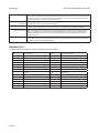
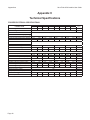
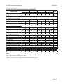
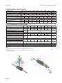
1
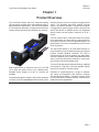
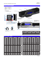
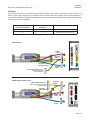
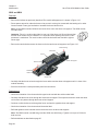
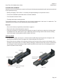
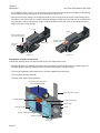
ServoTube 25/38 Module
USER GUIDE
Publication Ref: UM03016/A
Copley Motion Systems LLC
Luckyn Lane, Pipps Hill, Basildon, Essex SS14 3BW England
Tel: +44 (0)1268 287070
Fax +44 (0)1268 293344
Prelims
ServoTube 25/38 Module UserGuide
WARRANTY
Copley Motion Systems guarantees its equipment against faulty components for a period of twelve months from
delivery. Replacement components will be free of charge. Copley Motion Systems shall not in any event be liable
for consequential damage or loss.
Copley Motion Systems operates a customer care facility and all requests for repair and replacement should
be directed to the Customer Care Department. The serial number of the equipment should be quoted in any
communications. The right to change specification and price is reserved by Copley Motion Systems.
DISCLAIMER
Copley Motion Systems makes no guarantees of any kind with regard to this User Guide. Copley Motion Systems
shall not be liable for errors contained herein or for consequential or incidental damages incurred as a result of
acting on information contained in the manual.
CUSTOMER CARE
For enquiries relating to the operation and use of the ServoTube 25/38 Module described in this User Guide,
please contact the Customer Care Helpdesk, Telephone : +44 (0)1268 287070.
Copley Motion Systems LLC
Luckyn Lane, Pipps Hill, Basildon, Essex SS14 3BW England
Tel: +44 (0)1268 287070 Fax: +44 (0)1268 293344
(c) Copley Motion Systems 2008
INTERNATIONAL CONTACT DETAILS
website: http//www.copleycontrols.com
Page 2
World Headquarters, USA
Copley Controls Corp.
20 Dan Road,
Canton,
MA 02021
USA
European Headquarters
Copley Motion Systems LLC
Luckyn Lane,
Pipps Hill,
Basildon, Essex SS14 3BW
England
Tel: +1 781 828 8090
Fax: +1 781 828 1750
Tel: +44 (0)1268 287070
Fax: +44 (0)1268 293344
ServoTube 25/38 Module User Guide
Prelims
ServoTube 25/38 Module
USER GUIDE
Contents
Preliminary pages
Title page...................................................................................................................... 1
Copyright notice / disclaimer......................................................................................... 2
Contents list (this page)................................................................................................ 3
Warnings . .................................................................................................................... 4
Cautions........................................................................................................................ 5
Reader’s notes.............................................................................................................. 6
Chapters
1 Product overview.................................................................................................... 7
2 Installation............................................................................................................... 9
3 Maintenance......................................................................................................... 19
4 Service.................................................................................................................. 33
Appendices
A Glossary of terms & Abbreviations........................................................................ 37
B Trouble Shooting................................................................................................... 39
C Technical Specification......................................................................................... 40
Page 3
Prelims
ServoTube 25/38 Module UserGuide
WARNINGS
Warning symbols and meanings
In this User Manual warning symbols are used. These are intended to alert you to the potential hazards to personnel
which are associated with the equipment described, in all aspects of use, including handling, installation, operation
and maintenance.
Heart pacemakers. Personnel fitted with pacemakers must not handle or work on this equipment.
Strong magnets. The thrust rod contains powerful magnets and will strongly attract ferrous objects.
Damage can occur to computer disks and credit cards.
Electric shock. Potentially lethal voltages may be present during the commissioning and servicing
of this equipment. Isolate and disconnect all sources of electrical supply before working on the
equipment. Particular care needs to be taken when working on or around motor phase connections.
Crush hazard. The forcer may move unexpectedly. Always isolate all sources of electrical supply
before working on the equipment.
Heavy object. May need two people to lift.
General hazard. Follow the advice given.
Electrical safety
This equipment must be earthed.
EMC precautions
This equipment is intended for use in a light industrial environment. It is recommended that the following precautions
be observed during installation:
• Keep all cable lengths to a minimum.
• Provide as much physical separation as possible between power and sensor cables. In particular, avoid long,
parallel runs of cables.
• Maintain screen continuity throughout the cable run.
• Use 360 degree screen terminations where possible. “Pig-tail” terminations are not recommended.
• Ensure compliance with any local electrical and EMC regulations in force at the time of installation. This is the
responsibility of the User.
Page 4
ServoTube 25/38 Module User Guide
Prelims
READER’S NOTES
GENERAL
This manual describes the Installation, Maintenance and Spares of the ServoTube module.
ASSOCIATED PUBLICATIONS
The following publications are associated with the ServoTube 25/38 Module User Guide.
Title
ServoTube 25/38 Module Data sheet
Reference Number
DS01100
Copley Xenus (XTL-S) User Guide
-
Copley Xenus (XTL-S) Data Sheet
-
Copley Xenus Micro Panel (XSJ-S) User Guide
-
Copley Xenus Micro Panel (XSJ-S) Data Sheet
-
Page 5
Prelims
Page 6
ServoTube 25/38 Module UserGuide
Chapter 1
Overview
ServoTube 25/38 Module User Guide
Chapter 1
Product Overview
The ServoTube Module with fully integrated bearing
rail and position encoder offers unprecedented value in
high performance applications. The ServoTube Module
is a cost effective alternative to ballscrew and belt drive
systems where high speed and flexibility are required.
absolute accuracy, from a non-contact, integral position
sensor. The standard ServoTube position encoder
output is an industry standard 1V pk-pk sin/cos signal.
For applications requiring higher levels of accuracy, the
ServoTube Module is available with a fully integrated
optical position encoder giving a resolution of up to 1
micron.
The non-contact nature of the direct linear drive results
in life expectancy far above that for typical belt drive
and ballscrew systems, with the added advantage of no
deterioration in accuracy or repeatability over the entire
life of the product.
The ServoTube Module is an ideal OEM solution for
easy integration into pick-and-place gantry and general
purpose material handling machines. The load is
mounted directly to the forcer giving a very stable base.
Servotube Modules can be easily integrated with each
other or with other ServoTube products to create multiaxis systems with minimal design effort.
Eight models deliver a continuous force of 51 to 276 N
(11 to 62 lb) with peak forces of up to 1860 N (418 lb).
Standard stroke lengths of 21 mm to 1323 mm are
available.
The patented magnetic design of ServoTube generates
12 micron (0.47 mil) repeatability and 350 micron (14 mil)
The ServoTube has superior thermal efficiency, radiating
heat uniformly. High duty cycles are possible without
the need for forced-air or water cooling.
Servotube is complemented by a range of matched,
self tuning servo-amplifiers and indexers complete
with plug and play cabling. Amplifiers interface easily
to PLCs and feature CANopen network connectivity for
distributed control applications.
Page 7
Chapter 1
Overview
Page 8
ServoTube 25/38 Module User Guide
Chapter 2
Installation
ServoTube 25/38 Module User Guide
Chapter 2
Installation
UNPACKING
• Check packaging for signs of damage.
• Remove packaging. Do not discard. In the event of items requiring return, it is recommended that the original
packaging be used.
• Metal surfaces may be hot or below 0oC following prolonged storage.
• Ensure that the delivery note correctly reflects your order and the items delivered.
• Check equipment for signs of damage. Never use the equipment if it appears damaged in any way.
• Read the User Guide before installing and using this equipment.
INSTALLATION
Intended operating environment
This equipment is intended for use in an environment within the following conditions:
Operating temperature
0 to +40 °C
Storage temperature
-20 °C to +70 °C
Altitude (above mean sea level)
1000 m
Overvoltage category
II
Pollution degree
2
EMC
light industrial
Mechanical
Mounting module to user’s surface
For all modules, ensure that the mounting surface is as flat as possible. The module can be mounted by two
methods:
• Using the system clamp top fixings. Both sides should be clamped with a distance between clamp centres of
no more than 150 mm. Each M6 bolt should be tightened to a torque of 15 Nm.
• Using the M5 T-nut slots on the underside of the module. This requires access from underneath the mounting
surface. Both sides should be fixed with a distance between fixing centres of no more than 150 mm. Each M5
bolt should be tightened to a torque of 12 Nm.
All torque figures are non lubricated i.e. no thread lock.
Page 9
Chapter 2
Installation
ServoTube 25/38 Module User Guide
Mounting user’s payload to module moving forcer
The payload is mounted to the moving forcer top surface using the T-nut slots provided. It is recommended that a
minimum of four fixings are used.
• On the SM25 and SB25 modules, the fixings are M5 and should be tightened to a torque of 12 Nm.
• On the XM38 and XB38 modules, the fixings are M6 and should be tightened to a torque of 20 Nm.
Page 10
Chapter 2
Installation
ServoTube 25/38 Module User Guide
SM25 OUTLINE DRAWINGS
MAGNETIC THRUST ROD
(NOT LOAD BEARING)
FORCER
LH THRUST ROD
SUPPORT
CABLES:
1.
2.
3.
Ø7.6 POWER CABLE
Ø5.8 SENSOR CABLE
Ø4.5 ENCODER CABLE (OPTIONAL)
BEARING
LUBRICATION PORT
68
50
RH THRUST ROD
SUPPORT
(SEE NOTE)
17
SECTION A-A
94
D
65
18.5
1 2 3
33.0
C
38.5
21
50
DATUM ACTUATION AT 20.0mm
FROM END OF STROKE
78
FOR LARGER
DRAG CHAIN
(ORDER REF. I3)
86
0.5 NOM.
102 (CLAMP BOLT CENTRES)
4.8
10.5
LENGTH
10.3
NOTE: RH THRUST ROD SUPPORT SHOWN IS FOR 2504 MODULES ONLY. FOR ALL
OTHER SIZES THIS SUPPORT WILL BE AS LH THRUST ROD SUPPORT.
5.3
10.9
8.2
5.2
A
11.0
6.2
2.5
4.5
9.0
CUSTOMER ADJUSTABLE LIMIT
SWITCHES (OPTIONAL)
FACTORY SET FOR 5.0mm FROM
END OF STROKE
93.0
64
LINEAR ENCODER
(OPTIONAL)
FORCER LENGTH
A
0.5
EACH END
B
DRAG CHAIN
FOR CABLE ROUTING
(LARGER SIZE OPTIONAL)
SYSTEM CLAMPS
(MOUNTED NOT MORE
THAN 150mm APART)
EACH SIDE, IF REQUIRED
Approximate module mass (kg)
6.2
DETAIL B
DETAIL C
DETAIL D
SLOTS FOR M5 T-NUTS &
M6 SQUARE / HEX. NUTS
SLOTS FOR M4 SQUARE NUTS
SLOTS FOR M5 T-NUTS &
M6 SQUARE / HEX. NUTS
2504
2506
2508
2510
(0.0108 x L)+2.35
(0.0108 x L)+3.04
(0.0108 x L)+3.58
(0.0108 x L)+3.96
where L = Length in mm
SM25 STROKE TABLES
Length
253
278
Stroke
2508
2510
689
459
408
357
306
-
714
484
433
382
331
-
-
740
510
459
408
357
2508
2510
23
-
-
-
-
Stroke
2506
2506
48
Length
2504
2504
-
304
74
23
330
100
49
-
-
766
536
485
434
383
355
125
74
23
-
791
561
510
459
408
381
151
100
49
-
817
587
536
485
434
406
176
125
74
23
868
638
587
536
485
432
202
151
100
49
919
689
638
587
536
458
228
177
126
75
971
741
690
639
588
483
253
202
151
100
1022
792
741
690
639
509
279
228
177
126
1073
843
792
741
690
535
305
254
203
152
1125
895
844
793
742
177
1176
946
895
844
793
997
946
895
844
560
330
279
228
586
356
305
254
203
1227
612
382
331
280
229
1279
1049
998
947
896
637
407
356
305
254
1330
1100
1049
998
947
663
433
382
331
280
1381
1151
1100
1049
998
Page 11
Chapter 2
Installation
ServoTube 25/38 Module User Guide
SM38 OUTLINE DRAWINGS
MAGNETIC THRUST ROD
(NOT LOAD BEARING)
FORCER
THRUST ROD
SUPPORT
CABLES:
1.
2.
3.
Ø7.6 POWER CABLE
Ø5.8 SENSOR CABLE
Ø4.5 ENCODER CABLE (OPTIONAL)
BEARING
LUBRICATION PORT
84.0
60.0
SECTION A-A
110
D
73
38.0
1 2 3
C
38.5
21
0.5
EACH END
50
2.5
LENGTH
11.8
8.2
Approximate module mass (kg)
6.8
5.2
4.5
9.0
A
6.2
DETAIL B
CUSTOMER ADJUSTABLE LIMIT
SWITCHES (OPTIONAL)
FACTORY SET FOR 5.0mm FROM
END OF STROKE
14.0
8.2
4.8
0.50 NOM.
102 (CLAMP BOLT CENTRES)
DETAIL D
DETAIL C
SLOTS FOR M5 T-NUTS &
M6 SQUARE / HEX. NUTS
FORCER LENGTH
A
90
FOR LARGER
DRAG CHAIN
(ORDER REF. I3)
86
10.5
38.0
109.0
76
DATUM ACTUATION AT 20mm
FROM END OF STROKE
13.0
B
LINEAR ENCODER
(OPTIONAL)
DRAG CHAIN
FOR CABLE ROUTING
(LARGER SIZE OPTIONAL)
SYSTEM CLAMPS
(MOUNTED NOT LESS
THAN 150mm APART)
EACH SIDE, IF REQUIRED
3804
3806
3808
3810
(0.01563 x L)+4.26
(0.01563 x L)+5.23
(0.01563 x L)+6.21
(0.01563 x L)+7.19
where L = Length in mm
SLOTS FOR M6 T-NUTS &
M8 SQUARE / HEX. NUTS
SLOTS FOR M4 SQUARE NUTS
SM38 STROKE TABLES
Length
Stroke
3804
3806
3808
3810
338
40
-
-
-
373
75
-
-
-
409
111
40
-
445
147
76
480
182
111
516
218
147
551
253
587
289
623
Length
Stroke
3804
3806
3808
3810
1015
717
646
575
504
-
1051
753
682
611
540
-
-
1086
788
717
646
575
40
-
1122
824
753
682
611
76
-
1158
860
789
718
647
182
111
40
1193
895
824
753
682
218
147
76
1229
931
860
789
718
325
254
183
112
1264
966
895
824
753
658
360
289
218
147
1300
1002
931
860
789
694
396
325
254
183
1336
1038
967
896
825
730
432
361
290
219
1371
1073
1002
931
860
765
467
396
325
254
1407
1109
1038
967
896
801
503
432
361
290
1443
1145
1074
1003
932
837
539
468
397
326
1478
1180
1109
1038
967
872
574
503
432
361
1514
1216
1145
1074
1003
908
610
539
468
397
1550
1252
1181
1110
1039
944
646
575
504
433
1585
1287
1216
1145
1074
979
681
610
539
468
1621
1323
1252
1181
1110
Page 12
Chapter 2
Installation
ServoTube 25/38 Module User Guide
SB25 outline drawing
FORCER
BELLOWS
CABLES:
1.
2.
3.
Ø7.6 POWER CABLE
Ø5.8 SENSOR CABLE
Ø4.5 ENCODER CABLE (OPTIONAL)
SYSTEM END PLATE
68
17
SECTION A-A
1 2 3
65
94
18.5
38.5
21
FORCER LENGTH
B
CUSTOMER ADJUSTABLE LIMIT
SWITCHES (OPTIONAL)
FACTORY SET FOR 5.0mm FROM
END OF STROKE
50
LINEAR ENCODER
(OPTIONAL)
A
62
DATUM ACTUATION AT
20mm FROM END OFSTROKE
78
FOR LARGER
DRAG CHAIN
(ORDER REF. I3)
86
102 (CLAMP BOLT CENTRES)
4.8
10.5
2.5
A
8.2
5.2
4.5
9.0
DRAG CHAIN
FOR CABLE ROUTING
(LARGER SIZE OPTIONAL)
SYSTEM CLAMPS
(MOUNTED NOT MORE
THAN 150mm APART)
EACH SIDE, IF REQUIRED
C
LENGTH
6.2
DETAIL B
DETAIL C
SLOTS FOR M5 T-NUTS &
M6 SQUARE / HEX. NUTS
SLOTS FOR M4 SQUARE NUTS
Approximate module mass (kg)
2504
2506
2508
2510
(0.00885 x L)+2.49
(0.00885 x L)+2.94
(0.00885 x L)+3.49
(0.00885 x L)+3.85
where L = Length in mm
SB25 stroke table
2504
2506
2508
2510
2504
2506
2508
2510
Length
Stroke
Length
Stroke
Length
Stroke
Length
Stroke
Length
Stroke
Length
Stroke
Length
Stroke
Length
Stroke
271
21
-
-
-
-
-
-
889
456
861
405
832
354
804
303
297
47
-
-
-
-
-
-
929
482
901
431
873
380
844
329
322
72
322
21
-
-
-
-
970
508
941
457
913
406
885
355
348
98
348
47
-
-
-
-
1009
533
980
482
952
431
924
380
374
124
374
73
374
22
-
-
1049
559
1021
508
992
457
964
406
411
149
399
98
399
47
-
-
1088
584
1060
533
1031
482
1003
431
452
175
425
124
425
73
425
22
1169
636
1140
585
1112
534
1084
483
491
200
462
149
450
98
450
47
1248
687
1220
636
1191
585
1163
534
531
226
503
175
476
124
476
73
1327
738
1299
687
1271
636
1242
585
572
252
543
201
515
150
502
99
1406
789
1378
738
1350
687
1322
636
611
277
582
226
554
175
527
124
1486
840
1457
789
1429
738
1401
687
150
1567
892
1538
841
1510
790
1482
739
943
1618
892
1589
841
1561
790
651
303
623
252
594
201
566
690
328
662
277
633
226
605
175
1646
730
354
702
303
674
252
645
201
1725
994
1697
943
1669
892
1640
841
771
380
742
329
714
278
686
227
1804
1045
1776
994
1748
943
1720
892
810
405
781
354
753
303
725
252
1884
1096
1855
1045
1827
994
1799
943
850
431
822
380
793
329
765
278
1964
1148
1936
1097
1908
1046
1880
995
Page 13
Chapter 2
Installation
ServoTube 25/38 Module User Guide
XB38 OUTLINE DRAWINGS
FORCER
BELLOWS
CABLES:
1.
2.
3.
SYSTEM END PLATE
Ø7.6 POWER CABLE
Ø5.8 SENSOR CABLE
Ø4.5 ENCODER CABLE (OPTIONAL)
84
SECTION A-A
DRAG CHAIN
FOR CABLE ROUTING
(LARGER SIZE OPTIONAL)
110
SYSTEM CLAMPS
(MOUNTED NOT MORE
THAN 150mm APART)
EACH SIDE, IF REQUIRED
1 2 3
73
38
C
CUSTOMER ADJUSTABLE LIMIT
SWITCHES (OPTIONAL)
FACTORY SET FOR 5.0mm FROM
END OF STROKE
38.5
21
FORCER LENGTH
A
B
50
76
LINEAR ENCODER
(OPTIONAL)
DATUM ACTUATION AT
20mm FROM END OF STROKE
90
FOR LARGER
DRAG CHAIN
(ORDER REF. I3)
86
102 (CLAMP BOLT CENTRES)
A
4.8
8.2
5.2
4.5
9.0
LENGTH
2.5
10.5
Approximate module mass (kg)
3804
3806
3808
3810
(0.01199 x L)+5.28
(0.01199 x L)+6.31
(0.01199 x L)+7.33
(0.01199 x L)+8.28
6.2
DETAIL B
DETAIL C
SLOTS FOR M5 T-NUTS &
M6 SQUARE / HEX. NUTS
SLOTS FOR M4 SQUARE NUTS
where L = Length in mm
XB38 STROKE TABLES
3804
3806
3808
3810
Length
Stroke
Length
Stroke
Length
Stroke
Length
Stroke
387
23
-
-
-
-
-
-
Length
Stroke
Length
Stroke
Length
Stroke
Length
Stroke
423
59
-
-
-
-
-
-
1326
700
1287
629
1247
558
1208
487
735
1341
664
1302
593
1263
522
458
94
458
23
-
3804
-
-
-
1381
3806
3808
3810
494
130
494
59
-
-
-
-
1437
771
1397
700
1358
629
1318
558
530
166
530
95
530
24
-
-
1491
806
1452
735
1412
664
1373
593
565
201
565
130
565
59
-
-
1547
842
1508
771
1468
700
1429
629
606
237
601
166
601
95
601
24
1603
878
1563
807
1524
736
1485
665
661
272
636
201
636
130
636
59
1657
913
1618
842
1579
771
1539
700
717
308
677
237
672
166
672
95
1713
949
1674
878
1634
807
1595
736
773
344
733
273
708
202
708
131
1768
984
1728
913
1689
842
1650
771
827
379
788
308
748
237
743
166
1823
1020
1784
949
1745
878
1705
807
883
415
844
344
804
273
779
202
1879
1056
1840
985
1801
914
1761
843
938
450
898
379
859
308
819
237
1934
1091
1894
1020
1855
949
1816
878
994
486
954
415
915
344
875
273
1990
1127
1950
1056
1911
985
1872
914
1050
522
1010
451
971
380
931
309
2044
1162
2005
1091
1965
1020
1926
949
1104
557
1065
486
1025
415
986
344
2100
1198
2061
1127
2021
1056
1982
985
1160
593
1121
522
1081
451
1042
380
2156
1234
2117
1163
2077
1092
2038
1021
1214
628
1175
557
1136
486
1096
415
2210
1269
2171
1198
2132
1127
2092
1056
1270
664
1231
593
1192
522
1152
451
2266
1305
2227
1234
2188
1163
2148
1092
Page 14
Chapter 2
Installation
ServoTube 25/38 Module User Guide
Electrical
All electrical connections to the ServoTube Module are made via two cables. One carries power to the forcer
and the other carries signals from the position sensor. These cables are supplied either pre-terminated for a
specific drive amplifier or with flying leads. Where they are pre-terminated, simply plug the cables into the relevant
connectors on the drive amplifier.
FORCER POWER
CONNECTOR REFERENCE
POSITION SENSOR CONNECTOR
REFERENCE
AMPLIFIER
J2
J8
Copley Xenus (XTL-S)
J2
J6
Copley Xenus Micro Panel (XSJ-S)
XENUS (XTL-S)
J5
S1
J1
POWER
CABLE
ADAPTOR
CABLE
J6
J2
TO J2
J7
J3
TO J7
OPTIONAL
ENCODER CABLE
USER CONNECTIONS TO J7:
Pins 21-26 inclusive
are not available
XENUS MICRO PANEL (XSJ-S)
USER CONNECTIONS TO J5:
Pins 12-14 and 27-29 inclusive
are not available
J4
J8
SENSOR
CABLE
TO J8
ADAPTOR
CABLE
TO J5
OPTIONAL
ENCODER CABLE
J1
J5
J2
POWER
CABLE
TO J2
J6
J3
SENSOR
CABLE
J4
TO J6
J7
Page 15
Chapter 2
Installation
ServoTube 25/38 Module User Guide
The connections for the three options are shown in the table below:
SENSOR FUNCTION
+SIN
-SIN
+COS
-COS
+5Vd.c.
0V
+TH (Thermistor)
-TH (Thermistor)
SCREEN
D-(XTL-S)
14
13
12
11
4
5
10
15
1+ shell
15-way high density
D
J8
M-(XSJ-S)
1
11
2
12
17
7
20
14
1+ shell
20-way 2.54mm Mini
Mate
J6
F-Flying leads
Blue
Red
White
Brown
Yellow
Green
Pink
Grey
Screen
Forcer phase U
4
4
Black 1
Forcer phase V
Forcer phase W
Earth (forcer body)
SCREEN
3
2
1
1
4-way 5mm
pluggable terminal
J2
3
2
1
1
4-way 5mm
pluggable terminal
J2
Black 2
Black 3
Green/Yellow
Screen
Connector type
Amplifier connection
POWER FUNCTION
Connector type
Amplifier connection
Page 16
-
-
Chapter 2
Installation
ServoTube 25/38 Module User Guide
ADDITIONAL ENCODER
If an additional encoder has been specified there will be a third cable that should be connected to the relevant
encoder input on the drive amplifier used. When used with the Copley Xenus (XTL-S) or Xenus (XSJ-S) an adaptor
cable is supplied.
Connections are available via a 9-way D-sub male connector.
FUNCTION
+5Vd.c.
0V
A+
A-
B+
B-
Z+
Z-
Screen
5
1
2
6
4
8
3
7
Case
PIN NUMBER
LIMIT SWITCHES
WARNING. These limit switches are not intended as safety devices or as part of a system
intended to ensure personal safety. When two switches are mounted in close proximity (as
in the case of a left and right limit switch), a minimum of 30mm spacing between sense areas
must be maintained.
If limit switches have been specified there will be an additional cable per limit switch. These should be connected
to the relevent I/O on the drive amplifier.
The output for all types can be normally closed (NC) or normally open (NO) open collector transistor. The NC
ouptuts switch open when a limit is detected and current stops flowing in the LOAD. The NO ouputs switch closed
when a limit is detected and current starts flowing in the LOAD.
A red indicator shows when a limit is detected.
NPN
PNP
Brown (+V)
Brown (+V)
LOAD
Black (LOAD)
Black (LOAD)
LOAD
Blue (0V)
Blue (0V)
OVER-TEMPERATURE SENSOR
CAUTION. It is strongly recommended that the forcer over-temperature sensor is connected
to the drive amplifier or servo controller at all times in order to reduce the risk of damage to
the forcer due to excessive temperatures.
Page 17
Chapter 2
Installation
Page 18
ServoTube 25/38 Module User Guide
Chapter 3
Maintenance
ServoTube 25/38 Module User Guide
Chapter 3
Maintenance
WARNING
ISOLATE AND DISCONNECT ALL SOURCES OF ELECTRICAL SUPPLY BEFORE WORKING ON THE
EQUIPMENT.
PREVENTATIVE MAINTENANCE
All Modules
Bearing System
The ServoTube modules are supplied as complete, ready to use mechanical systems. Each system incorporates a
profile rail re-circulating ball bearing system for support and guidance. The bearing carriages, to which the moving
forcer is attached, are fully charged with grease before delivery. During the life of the system, this grease will need
to be replenished. The interval for replenishment will vary depending on the parameters of operation. Systems
carrying heavy payloads and travelling at high speeds with fast acceleration and deceleration will need re-greasing
more often than systems carrying light payloads and travelling at slower speeds. However, as a general guide,
re-greasing is recommended at intervals of 1000 km.
In order to re-grease the bearing carriages effectively and with minimum spillage, a delivery tube with a specially
designed nozzle to engage with the lubrication nipples on the bearing carriages is required. These are available
from your supplier complete with a fully charged, small (70 g) side lever grease gun.
Description
Order Code
Standard lithium based grease
400 999 120
CAUTION. Different types of grease should never be mixed as they can cause damage to the
bearing rail due to their incompatibility. The bearing system must only be lubricated via the
bearing carriages. Do not lubricate the bearing rail. Do not lubricate the thrust rod, it is not a
bearing surface.
Page 19
Chapter 3
Maintenance
ServoTube 25/38 Module User Guide
Re-greasing
Procedure for modules without bellows (SM25 and XM38)
• Move the forcer to one end.
• Each thrust rod end support has an M10 through
hole which lines up with the bearing carriage
lubrication nipple. These can be seen in Figure 3.1.
For clarity, the forcer has been removed.
• Insert the grease gun delivery tube through the
M10 hole and engage the nozzle with the bearing
carriage lubrication nipple. The grease gun nozzle
does not attach itself so opposing pressure will
need to be applied to the grease gun and forcer.
• Transfer of grease into the bearing carriages is
achieved by squeezing the grease gun lever 1-2
times. If grease is seen coming out of the bearing
carriages stop squeezing the lever. Over greasing
does not damage the bearings but is not desirable.
Lubrication nipple
Thrust rod end support
M10 through hole
for access to
lubrication nipple
• Remove the grease gun.
Figure 3.1
Note. There is only one bearing carriage on the SM2504 module.
• Move the forcer to the opposite end. Repeat the above steps to re-grease the other bearing carriage.
• Move the forcer by hand to and fro in order to distribute the grease.
Note. If too much grease has been transferred into the bearing carriages the excess should be cleaned away.
If left, it may interfere with the function of an optional encoder where fitted.
Procedure for modules with bellows (SB25 and XB38)
To re-grease an SB module, it is necessary first to remove the bellows.
• Refer to ‘Removing the Bellows’ on page 24.
• The lubrication nipple can be seen in Figure 3.2
after the bellows have been removed. For clarity,
the forcer has been removed.
• Engage the grease gun delivery tube and the
nozzle with the bearing carriage lubrication nipple.
The grease gun nozzle does not attach itself so
opposing pressure will need to be applied to the
grease gun and forcer.
• Transfer of grease into the bearing carriages is
achieved by squeezing the grease gun lever 1-2
times. If grease is seen coming out of the bearing
carriages stop squeezing the lever. Over greasing
does not damage the bearings but is not desirable.
• Remove the grease gun.
Bearing
carriage
Lubrication
nipple
Figure 3.2
Page 20
ServoTube 25/38 Module User Guide
Chapter 3
Maintenance
Note. There is only one bearing carriage on the SB2504 module.
• Move the forcer to the other end. Repeat the above steps to re-grease the other bearing carriage.
• Move the forcer by hand to and fro in order to distribute the grease.
Note. If too much grease has been transferred into the bearing carriages the excess should be cleaned away.
If left, it may interfere with the function of an optional encoder where fitted.
• Replace the bellows as described on page 25.
Thrust rod
The thrust rod must be kept clean and central to the forcer bore to avoid damage to the windings inside the forcer.
Check that the thrust rod is centrally aligned by moving the forcer along the entire length of the thrust rod and
observing the gap between the thrust rod and forcer bore.
If the thrust rod is becoming polished in places, this is usually an indication that the forcer is coming into contact
with the thrust rod. Check the surface of the thrust rod for any raised areas that may damage the inside lining of
the forcer. A soft cloth can be used to clean the thrust rod and self adhesive tape can be used to lift off any ferrous
debris that may be attracted to it.
Forcer
Forcers have a fluoropolymer inner lining that does not require maintenance. However, when carrying out checks,
a visual inspection should be made to ensure there is nothing trapped in the ends of the forcer.
Cables
Check that all connecting cables are secured and not under strain. Inspect cables for signs of wear.
Encoder (where fitted)
The encoder scale should be cleaned with a soft, lint free cloth to remove any oil, grease or dirt. Under no
circumstances must solvents be used on optical encoder scales as the protective lacquer coating may become
damaged.
Bellows
On module systems with bellows (SB25 and XB38), periodically remove any debris from the bellows folds that may
reduce the movement of the forcer.
Page 21
Chapter 3
Maintenance
ServoTube 25/38 Module User Guide
CORRECTIVE MAINTENANCE
The corrective maintenance by the user is limited to the following items:
• Power and Sensor cables
• Thrust rod
• Bellows (SB25 and XB38 only)
• Forcer
• Encoder readhead
CABLE REPLACEMENT
Note. It is not possible to replace an encoder cable. If an encoder cable needs replacing, the complete encoder
assembly will have to be replaced. See ENCODER READHEAD on page 31 in this chapter.
CAUTION. If the optional Renishaw encoder is fitted, it has an integral cable that also runs
through the drag chain. Take care not to damage this item when releasing the other cables.
Removal
• Unclip the covers of all links in the drag chain. These are shown coloured green in Figure 3.3. They can be
removed as a single item by progressively pulling up the tongue of the first cover until all are unclipped.
Link covers
identified by
green highlight
Figure 3.3
• Remove any cable ties that have been used to hold the cables in position.
Link covers
removed
Figure 3.4
• With the cover section removed the cables can now be removed from the drag chain, see Figure 3.4.
Page 22
Chapter 3
Maintenance
ServoTube 25/38 Module User Guide
• To gain access to the cable termination connectors inside the pod, unscrew the four M3 fixing screws, see
Figure 3.5.
Note that the pod lid fixing screws are of different lengths. Make a record from where each fixing is removed
so they can be correctly replaced later.
Sensor cable
M3 lid fixing screws (4 off)
Power cable
Pod lid
Figure 3.5
PIN NUMBER
FUNCTION
1
Phase U
2
Phase V
3
Phase W
Chassis
Earth/Screen
PIN
NUMBER
FUNCTION
1
2
3
4
5
6
7
8
+SIN
-SIN
+COS
-COS
+5Vd.c.
0V
+TH (Thermistor)
-TH (Thermistor)
TB1
Figure 3.6
PL1
Figure 3.7
• Remove the pod lid from the termination box to reveal the cable termination connectors inside, see Figure 3.6
and Figure 3.7.
• Loosen the two fixings on the cable clamp to fully free the cables.
• Disconnect the power cable from the PCB mounted screw terminal connector TB1, and unscrew the earth/
screen terminal to remove the eyelet fastened to the cable screen terminal.
• Unplug the sensor cable from the vertical PCB at connector PL1 (see Figure 3.7).
• Unscrew the pressure nut from the cable gland and carefully pull the two cables out of the pod through the
cable gland. The cable assembly will comprise sensor and power cables, the pressure nut and at the other
end of the cables, the amplifier connectors.
Note. The cable assembly is the replacement item when either power or sensor cable needs to be replaced.
Replacement
Re-fitting the cable assembly is the reverse of the removal procedure.
• Feed the power and sensor cables to be connected to the connectors in the pod, through the cable gland to
reach TB1 and PL1.
• Plug PL1 into its connector on the edge-mounted PCB.
• Connect the power cable leads to TB1 and the earthing point. Refer to Figure 3.6 for the connection table.
Page 23
Chapter 3
Maintenance
ServoTube 25/38 Module User Guide
• Refit and tighten the cable retaining clamp.
• Screw on and tighten the pressure nut.
• Replace the pod cover taking care not to damage the sealing gasket on the pod.
• Fit the M3 fixings according to the record made when they were removed, and tighten to a torque of 0.7 Nm.
• Place the cables back inside the drag chain.
• Fit new cable ties to secure the cables as originally fitted.
• Re-clip the covers that were previously unclipped.
BELLOWS REPLACEMENT
Removal
• Remove the two M6 button head fixings securing the bellows system end plate to the backing bar, Figure 3.8.
Backing bar
System endplate
Remove these screws
Figure 3.8
• Move the forcer towards the side being replaced and slide the bellows with attached system end plate, out of
the module backing bar.
• Fold the bellows (not shown) still connected to the system end plate, back over the top of the forcer body to
give access to the fixings that secure the bellows fixing plate to the forcer, see Figure 3.9.
Forcer
• Remove the four M3 countersunk fixings that secure the bellows fixing plate to the forcer and remove the
bellows from the module assembly. The module with bellows removed is shown in Figure 3.10.
Bellows
fixing
plate
M3 CSK
fixings (4 off)
Figure 3.9
Page 24
Figure 3.10
Chapter 3
Maintenance
ServoTube 25/38 Module User Guide
• Extract the bellows fixing plate from the last fold on the bellows.
• Remove the two M4 button head fixings securing the bellows to the bellows fixing plate in the first fold of the
bellows.
• Extract this fixing plate from the bellows.
Replacement
• Insert the bellows fixing plate into the first fold on the bellows (the end that connects to the system end plate).
• Replace the two M4 fixings that secure the bellows to the system end plate and tighten to a torque of 0.7 Nm,
see Figure 3.11.
Bellows
M4 screws (2 off)
First fold position
System end plate
Figure 3.11
• Insert the second bellows fixing plate into the last fold on the bellows (the forcer end).
• Partially slide the bellows back onto the module assembly.
• Move the forcer towards the side being replaced and slide the bellows up to the end of the forcer body.
• Fold the bellows back over the top of the forcer body to enable access to the fixings that secure the bellows
fixing plate to the forcer body.
• Replace the four M3 countersunk fixings that secure the bellows to the forcer body and tighten to a torque of
0.7 Nm.
• Slide the bellows back onto the module assembly.
• Replace the two M6 button head fixings to secure the bellows system end plate to the module backing bar
and tighten to a torque of 4 Nm.
Page 25
Chapter 3
Maintenance
ServoTube 25/38 Module User Guide
THRUST ROD REPLACEMENT
SM25 and XM38
Removal
• Move the forcer to the centre of the module, Figure 3.12.
Forcer
Position forcer to
centre of module
Figure 3.12
• Place spacers around or under the thrust rod to prevent it coming into contact with the bearing rail or other
ferrous material. Foam pipe insulation or wooden blocks are ideal for this.
• Loosen the two M10 bolts on each of the thrust rod end supports.
Loosen
Thrust rod
Thrust rod support
Loosen
Thrust rod support
Carefully slide
thrust rod out of module
Figure 3.13
Note. When an SM2504 is fitted with an optional encoder, one of the thrust rod supports has only one M10
bolt).
Important. There is a serial number label on one end of the thrust rod. Record the end that
has the serial number and its orientation. It is important when replacing the thrust rod this
parameter is maintained. The serial number should be horizontal and read left to right as
shown right.
• Carefully slide the thrust rod out through the thrust rod supports and forcer (Figure 3.13) until it is clear of the
module assembly, see Figure 3.14.
• Store the thrust rod in a safe place away from ferrous material.
Page 26
Chapter 3
Maintenance
ServoTube 25/38 Module User Guide
Thrust rod removed
from module
Figure 3.14
Replacement
• Check the orientation of the thrust rod with regard to the end with the serial number label.
• Carefully slide the thrust rod in through the first thrust rod support. Place spacers around or under the thrust
rod as soon as it passes through the thrust rod support.
• Continue to slide the thrust rod to pass through the forcer and into the other thrust rod support.
• Check the orientation of the thrust rod serial number label.
• Tighten the M10 fixings in the thrust rod support to a torque of 50 Nm.
Page 27
Chapter 3
Maintenance
ServoTube 25/38 Module User Guide
SB25 and XB38
Removal
• Remove the bellows as previously described.The module will appear as it is shown in Figure 3.15.
• Place spacers around or under the thrust rod to prevent it coming into contact with the bearing rail or other
ferrous material. Foam pipe insulation or wooden blocks are ideal for this.
Note. On the SB25 modules, M8 bolts secure the thrust rod to the thrust rod supports. The XB38 module
uses M10 bolts.
Important. There is a serial number label on one end of the thrust rod. Record the end that
has the serial number and its orientation. It is important when replacing the thrust rod this
parameter is maintained. The serial number should be horizontal and read left to right as
shown right.
• Remove the two bolts that secure the thrust rod to the two thrust rod supports, see Figure 3.15.
Remove fixing
Thrust rod
Forcer
Thrust rod support
Remove fixing
Withdraw
thrust rod
Thrust rod support
Figure 3.15
• Carefully slide the thrust rod out through the forcer and across the thrust rod supports until it is clear of the
module assembly.
• Store the thrust rod in a safe place away from ferrous material.
Replacement
• Check the orientation of the thrust rod with regard to the end with the serial number label.
• Carefully slide the thrust rod in through the first thrust rod support. Place spacers around or under the thrust
rod as soon as it passes through the thrust rod end support.
• Continue to slide the thrust rod through the forcer and into the opposite thrust rod support.
• Check the orientation of the thrust rod serial number label.
• Refit and tighten the two bolts that secure the thrust rod to the thrust rod supports.
Note. The SB25 module uses M8 fixings and the XB38 uses M10 fixings. Tighten to a torque of 50 Nm for
both versions.
• Refit the bellows as described on page 25.
Page 28
Chapter 3
Maintenance
ServoTube 25/38 Module User Guide
FORCER REPLACEMENT
When the forcer is removed from the module, it will have the following items attached that will need to be transferred
to the replacement forcer.
• Bearing carriage(s). There will be 1 or 2 bearing carriages depending on the particular version.
• The encoder readhead bracket fitted with the encoder readhead.
• The limit switch actuator if fitted.
• The drag chain upper mounting bracket.
The pod base however, is an integral part of the forcer and is programmed for the forcer it is attached to. The
replacement forcer will have its own specifically programmed pod base.
Removal
• Remove the bellows (if applicable) as described on page 24.
• Remove the thrust rod as described on page 26.
• Follow the procedure for Cable Replacement described on page 22 and free the cables from the drag chain,
but do not remove the cables from the pod. Additionally remove the drag chain link that secures the drag
chain to the upper mounting bracket which is fitted to the forcer.
SM25 and XM38
• For the SM25 or XM38, see Figure 3.16. Remove the three M6 fixings securing a thrust rod support to the
backing bar and slide the thrust rod support out of the backing bar, see Figure 3.17.
• Remove the forcer by sliding it off the bearing rail taking care to keep the forcer square to the bearing rail so
that balls are not lost from the re-circulating bearing carriage(s). If balls do fall out they can be re-inserted into
the carriages. Push the ball bearings using a small screwdriver into the end of the re-circulating path at the
plastic end plates on the carriage.
Bearing rail
Forcer
Forcer
Thrust rod support
Move forcer off end
of bearing rail
Backing bar
Remove these screws and thrust rod support
Figure 3.16
Figure 3.17
Page 29
Chapter 3
Maintenance
ServoTube 25/38 Module User Guide
• On the SB25 or XB38, Figure 3.18, remove the four M4 fixings securing one thrust rod support to the backing
bar and slide the thrust rod support out of the backing bar, Figure 3.19.
• Remove the forcer by sliding it off the bearing rail taking care to keep the forcer square to the bearing rail so
that balls are not lost from the re-circulating bearing carriage(s). If balls do fall out they can be re-inserted into
the carriages. Push the ball bearings using a small screwdriver into the end of the re-circulating path at the
plastic end plates on the carriage.
Forcer
Forcer
Remove these screws
and thrust rod support
Backing bar
Thrust rod
support
Move forcer off end
of bearing rail
Bearing rail
Bearing rail
Figure 3.18
Figure 3.19
Preparation of replacement forcer
Transfer the following items from the removed forcer to the replacement forcer:
• Bearing carriage(s). On SM/SB25 align the bearing carriages level with and parallel to the datum edge. On
XM/XB38 align the bearing carriages to be 8 mm below and parallel to the datum edge
• The encoder readhead bracket fitted with the encoder readhead (optional items)
• The limit switch actuator (optional).
• The drag chain upper mounting bracket.
Pod housing (non-removable)
with removable lid fitted
Upper drag chain bracket
Encoder readhead
Encoder cable clamp
Datum edge
Forcer
Bearing carriage
Encoder readhead bracket
Bearing carriage
Figure 3.20
Page 30
ServoTube 25/38 Module User Guide
Chapter 3
Maintenance
Replacement
• Slide the newly assembled forcer on to the bearing rail taking care to keep the forcer square to the bearing
rail so that balls are not lost from the re-circulating bearing carriage(s). If balls do fall out they can be reinserted into the carriages. Push the ball bearings using a small screwdriver into the end of the re-circulating
path at the plastic end plates on the carriage.
• On the SB25 or XB38: slide the thrust rod support on to the backing bar and tighten the four M4 fixngs to a
torque of 4 Nm.
• On the SM25 or XM38: refit the thrust rod support to the end of the backing bar and secure using the three
M6 fixings tightened to a torque of 20 Nm.
• Replace the thrust rod as described on page 27.
• Replace the cable assembly as described on page 22.
• Replace the bellows (if fitted) as described on page 25.
ENCODER READHEAD (Optional item)
Before commencing any work, it is important to note that the encoder may require alignment to achieve optimum
performance after replacement.
Removal
• If applicable, remove the bellows as described on page 24.
• Remove the thrust rod as described on page 26.
• Remove the forcer as described on page 28.
• On the underside of the forcer remove the M3 countersunk fixing and clamp holding the encoder cable to the
forcer body. Refer to Figure 3.20 for location of the encoder readhead bracket and encoder readhead.
• Remove the encoder (cable) clamp.
• Undo the four M3 x 6 fixings to remove the encoder bracket.
• Undo the two M3 x 10 fixings to remove the encoder readhead with integral cable.
Replacement
• Refit the replacement encoder readhead to the encoder bracket using the two M3 x 10 fixings and tighten to a
torque of 0.7 Nm.
• Refit the encoder bracket to the forcer using the M3 x 6 fixings.
• Route the encoder cable via the clamping groove in the forcer and refit the encoder cable clamp with its
M3 x 8 countersunk screw to secure the encoder cable to the forcer body. Tighten to a torque of 0.7 Nm.
• Slide the forcer on to the bearing rail taking care to keep the forcer square to the bearing rail so that balls
are not lost from the re-circulating bearing carriage(s). If balls do fall out they can be re-inserted into the
carriages. Push the ball bearings using a small screwdriver into the end of the re-circulating path at the plastic
end plates on the carriage.
Page 31
Chapter 3
Maintenance
ServoTube 25/38 Module User Guide
Alignment
The encoder may need aligning. To check:
• Connect the encoder to the control system and apply power to the encoder only.
• Move the forcer along the entire length of the module and check that the LED indicator on the back of the
readhead lights up green. It will light up red as it passes over the reference mark. If this does not happen,
alignment is necessary.
• Remove the forcer by sliding it off the bearing rail taking care to keep the forcer square to the bearing rail so
that balls are not lost from the re-circulating bearing carriage(s). If balls do fall out they can be re-inserted into
the carriages. Push the ball bearings using a small screwdriver into the end of the re-circulating path at the
plastic end plates on the carriage.
• On the underside of the forcer, loosen the four M3 x 6 fixings securing encoder bracket to the forcer body.
Note. The fixings should be loosened just enough to allow movement of the encoder bracket.
• Slide the forcer onto the bearing rail taking care to keep the forcer square to the bearing rail so that balls
are not lost from the re-circulating bearing carriage(s). Should balls be lost they can be re-inserted into the
carriages by pushing them with a small screwdriver into the end of the re-circulating path by the plastic end
plates on the carriage.
• Connect the encoder to the control system and apply power to the encoder only. Using a thin piece of rigid
plastic (100mm x 20mm x 1mm), adjust the encoder readhead by sliding the plastic between the backing bar
and forcer. Push the readhead until the LED on the back of the readhead lights up green.
• Move the forcer along the entire length of the module and check that the LED indicator on the back of the
readhead lights up green. It will light up red as it passes over the reference mark.
• Slide the forcer onto the bearing rail taking care to keep the forcer square to the bearing rail so that balls
are not lost from the re-circulating bearing carriage(s). Should balls be lost they can be re-inserted into the
carriages by pushing them with a small screwdriver into the end of the re-circulating path by the plastic end
plates on the carriage.
• On the underside of the forcer, tighten the four M3 x 6 fixings that secure the encoder bracket to the forcer
body and tighten each to a torque of 0.7 Nm.
• Refit the forcer, thrust rod and bellows as previously described.
BEARING REPLACEMENT
Should excessive play be detected in the bearing system the bearing will need replacing. It is recommended that
all bearing carriages and the bearing rail are replaced at the same time.
Due to the complex nature of the process and specialist equipment required, please contact your supplier regarding
replacement.
Page 32
Chapter 4
Service
ServoTube 25/38 module User Guide
Chapter 4
Service
SERVICE
Should you need to return any items to Copley Motion Systems, before doing so, please call our Sales coordinator
on +44 (0)1268 287070 or send a fax to +44 (0)1268 293344 in order to obtain an RMA (Returned Materials
Authorisation) number. The RMA number should then be quoted on all items returned and quoted for all
enquiries.
Please note that when returning items it is recommended that the original packaging be used.
ACCESSORIES AND SPARES
The Accessories and Spares for the modules are listed in Tables 4.1 and Table 4.2.
Table 4.1 Accessories
Description
Order Code
Grease Gun Kit
400 999 120
Grease Spares
Grease Gun Applicator/Nozzle
400 999 007
Standard Grease 150 ml
035 630 016
Mounting Hardware
M5 T-nut (10 off pack)
045 205 007
M6 T-nut (10 off pack)
046 205 007
M4 Square Nut (100 off pack)
044 205 000
M6 Square Nut (100 off pack)
046 140 010
System clamp - Single Hole
035 915 027
System clamp - Four Hole
035 915 028
Page 33
Chapter 4
Service
ServoTube 25/38 module User Guide
Table 4.2 Spares
Description
Length
Order Code
5 µm readhead
3 metre cable
350 590 161
5 µm readhead
5 metre cable
350 590 162
1 µm readhead
3 metre cable
350 590 157
1 µm readhead
5 metre cable
350 590 158
NPN Limit Switch, NC
2 metre cable
200 735 104F
PNP Limit Switch, NC
2 metre cable
200 735 103F
NPN Robotic Switch, NC
5 metre robotic cable
200 735 102F
PNP Robotic Switch, NC
5 metre robotic cable
200 735 101F
NPN Limit Switch, NO
2 metre cable
200 735 094F
PNP Limit Switch, NO
2 metre cable
200 735 093F
NPN Robotic Switch, NO
5 metre robotic cable
200 735 092F
PNP Robotic Switch, NO
5 metre robotic cable
200 735 091F
Renishaw readhead replacements
Limit Switches
Drag Chain
I2 (Igus 15.2) drag chain
170 720 023
I3 (Igus 15.3) drag chain
170 720 025
To place an order for spare parts please telephone or fax your order to the Sales co-ordinator:
Tel: +44 (0)1268 287070
Fax: +44 (0)1268 293344
Page 34
Appendices
ServoTube 25/38 module User Guide
Appendices
CONTENTS
APPENDIX A - GLOSSARY OF TERMS & ABBREVIATIONS
APPENDIX B - TROUBLE SHOOTING
APPENDIX C - TECHNICAL SPECIFICATION
Page 35
Appendices
Page 36
ServoTube 25/38 module User Guide
Appendices
ServoTube 25/38 module User Guide
Appendix A
Glossary of Terms & Abbreviations
GLOSSARY OF TERMS
TERM
Peak force
DESCRIPTION OF TERM
Peak force is the force produced when the peak current is applied to the forcer. It is the product of Force
constant (N/Apk) and Peak current (Apk).
The forcer is not moving, there is no forced cooling and no additional heat-sinking. The duration of the peak
force is thermally limited and is therefore only allowable for a period of 1 second.
Continuous stall force
Continuous stall force is the force produced when the continuous current is applied to the forcer.
It is the product : Force constant (N/Apk) x Continuous stall current (Apk)
or : Force constant (N/Arms) x Continuous stall current (Arms).
The forcer is not moving and there is no forced cooling.
It is quoted with and without the addition of a 25 x 25 x 2.5 cm heatsink plate mounted with thermal grease
to the mounting surface of the forcer.
Peak current
Peak current is the current required to heat the forcer phases to their maximum operating temperature
when the ambient temperature is 25°C, the forcer is not moving, there is no forced cooling and no
additional heat-sinking.
It is the maximum allowable current before demagnetisation of the magnets occurs when the magnet
temperature is 100°C.
The duration of the peak current is thermally limited and is therefore only allowable for a period of 1 second.
Continuous stall current
Continuous stall current is the current required to heat the forcer phases to their maximum operating
temperature when the ambient temperature is 25°C, the forcer is not moving and there is no forced cooling.
It is quoted with and without the addition of a 25 x 25 x 2.5 cm heatsink plate mounted with thermal grease
to the mounting surface of the forcer.
Force constant
Force constant is the peak force produced when 1 ampere (peak) flows into one phase and 0.5 ampere
(peak) flows out of the remaining two phases (as in sinusoidal commutation) quoted in N/Apk. Alternatively,
it is the peak force produced when 0.707 ampere (rms) flows into one phase and 0.353 ampere (rms) flows
out of the remaining two phases (again as in sinusoidal commutation) quoted in N/Arms.
Back EMF Back EMF constant is the peak phase to phase voltage generated when the forcer is travelling at a velocity
of 1m/s.
Fundamental forcer
constant
Fundamental forcer constant is the continuous stall force divided by the square root of the power dissipated
in the forcer at that continuous stall force.
Eddy current loss
Eddy current loss is the amount of opposing force produced by the forcer when it is travelling at a velocity
of 1m/s.
Sleeve cogging force
Sleeve clogging force is the amount of force variation produced by having an iron sleeve. The variation is
independent of forcer current.
Resistance
Resistance is measured phase to phase at temperatures of 25°C and 100°C.
Inductance
Inductance is measured phase to phase at a frequency of 1 kHz. The actual value of inductance varies as
the forcer position varies so it is the minimum value that is quoted.
Electrical time constant
Continuous working voltage
Pole pitch
Electrical time constant is the time taken for a step current input to the forcer to reach 63.2% of its value.
Continuous working voltage is the maximum allowable continuous voltage between any two forcer phases
or between any forcer phase and the forcer safety earth.
Pole pitch is the distance in millimetres for one complete electrical cycle (between like magnetic poles).
Page 37
Appendices
ServoTube 25/38 module User Guide
Power dissipation
Maximum phase
temperature
Rthphase-houslng
Power dissipation is the maximum power that can be dissipated by the forcer when the forcer phases are at
their maximum operating temperature, the ambient temperature is 25°C, the forcer is not moving and there
is no forced cooling. It is quoted with and without the addition of a 25 x 25 x 2.5cm heatsink plate mounted
with thermal grease to the mounting surface of the forcer.
Maximum phase temperature is the maximum operating temperature for the forcer phases. It is limited to
provide a safe operating temperature for the magnets.
Rthphase-houslng is the temperature rise from the forcer housing to the forcer phases for an input power of
1 watt to the forcer. The forcer is not moving, there is no forced cooling and no additional heatsinking.
Rthhousing-ambient
Rthhousing-ambient is the temperature rise from ambient temperature to the forcer housing for an input
power of 1 watt to the forcer. The forcer is not moving and there is no forced cooling. It is quoted with and
without the addition of a 25 x 25 x 2.5cm heatsink plate mounted with thermal grease to the mounting
surface of the forcer.
Thermal time constant
Thermal time constant is the time taken for the forcer phases to cool to 36.8% of the difference between
forcer phase and ambient temperatures when there is no current flowing, the forcer is not moving there is
no forced cooling and no additional heatsinking.
ABBREVIATIONS
The abbreviations used in this Guide are listed in the following table.
Apk
Ampere peak
PCB
Printed circuit board
Arms
Ampere root mean square
PUR
Polyurethane
AWG
American Wire Gauge
PVC
Poly Vinyl Chloride
COS
cosine
s
second
d.c.
direct current
SIN
sine
EMC
Electro-Magnetic Compatibility
TYP
Typical
EMF
Electro-Motive Force
UL
Underwriters Laboratory
kg
kilogramme
V
Volt
m
metre
Vpk
Volt peak
mA
milliampere
Vpk-pk
Volt peak to peak
mH
millihenry
Vrms
Volt root mean square
mm
millimetre
W
Watt
MTG
Mounting
°C degrees
Celsius
N
Newton
mm
micrometre (micron)
PTC
Positive Temperature Coefficient
Page 38
Appendices
ServoTube 25/38 module User Guide
Appendix B
Troubleshooting
TROUBLESHOOTING CHART
Check to see if the problem you are experiencing is listed in the chart below. If the problem cannot be solved with
reference to this chart, contact the customer services department.
Fault
Possible cause
Action
Forcer fails to move and
produces no force.
1. Drive not powered.
1. Apply power to drive.
2. Forcer phase connections not made.
2. Check forcer phase connections on drive.
3. Forcer over-temperature sensor not
connected.
3. Check forcer over-temperature sensor
connections on drive.
4. Forcer over-temperature.
4. Allow forcer to cool.
1. One or more forcer phase connections
not made or made incorrectly.
1. Check forcer phase connections on drive.
2. One or more position sensor connections
not made or made incorrectly.
2. Check position sensor connections on drive.
Forcer fails to move but does
produce force.
3. Forcer/thrust rod mechanically blocked.
3. Check forcer/thrust rod is free to move.
Forcer moves but is jerky in
motion.
Incorrect pole pitch set up or phase offset
between position sensor and forcer back
emf.
Check drive or controller set up.
Forcer moves in wrong
direction.
One or more position sensor and forcer
phase connections made incorrectly.
Check position sensor and forcer phase
connections on drive.
Page 39
Appendices
ServoTube 25/38 module User Guide
Appendix C
Technical Specifications
FORCER ELECTRICAL SPECIFICATIONS
FORCER TYPE
Peak force @ 25oC ambient for 1 sec
Peak current @ 25oC ambient for 1 sec
With 25 x 25 x2.5cm heatsink plate
Continuous stall force @ 25oC ambient (2)
Continuous stall current @ 25oC ambient
Without heatsink plate
Continuous stall force @ 25oC ambient (2)
Continuous stall current @ 25oC ambient
Force constant (sine commutation)
Back EMF constant (phase to phase)
Fundamental forcer constant
Eddy current loss
Resistance @ 25oC (phase to phase)
Resistance @ 100oC (phase to phase)
Inductance @ 1kHz (phase to phase)
Electrical time constant
Maximum working voltage
Pole pitch (one electrical cycle)
S(1)
2504
312
P(1)
S(1)
156
468
2506
P(1)
S(1)
234
2508
624
P(1)
S(1)
312
780
2510
P(1)
390
20
51.2
69.5
4.62
2.10
4.20
1.96
3.92
1.86
3.72
N
Arms
3.27
6.54
2.97
5.94
2.77
5.54
2.62
5.24
Apk
1.92
3.84
1.80
3.60
1.70
3.40
1.63
3.26
N
Arms
2.72
5.44
2.54
5.08
2.41
4.82
2.31
4.62
Apk
22.1
15.6
18.0
11.0
7.8
9.0
33.1
23.4
27.0
16.5
11.7
13.5
44.1
31.2
36.0
22.0
15.6
18.0
55.2
39.0
45.0
27.6
19.5
22.5
2.25
2.91
1.46
9.13
15.58
12.03
3.01
15.51
3.88
7.80
1.95
N/Arms
N/Apk
Vpk/m/s
N/√W
N/m/s
Ohm
Ohm
mH
ms
V d.c.
mm
59.5
6.47
9.51
6.02
7.75
3.90
75.1
7.92
12.55
1.50
1.94
0.97
9.02
11.63
5.85
102.4
N
Apk
2.31
42.5
86.4
units
90.0
10.24
18.61
15.04
3.76
19.39
4.85
9.75
2.44
0.65
380
51.2
Peak acceleration (3)
222
111
222
111
235
117
255
127
m/s2
Maximum speed
8.5
7.3
6.4
7.1
5.3
7.3
4.5
6.7
m/s
Page 40
(4)
Appendices
ServoTube 25/38 module User Guide
FORCER ELECTRICAL SPECIFICATIONS (continued)
FORCER TYPE
S
3804
(1)
Peak force @ 25oC ambient for 1 sec
Peak current @ 25oC ambient for 1 sec
744
Force constant (sine commutation)
Back EMF constant (phase to phase)
Fundamental forcer constant
Eddy current loss
Sleeve cogging force
Resistance @ 25oC (phase to phase)
Resistance @ 100oC (phase to phase)
Inductance @ 1kHz (phase to phase)
Electrical time constant
Maximum working voltage
Pole pitch (one electrical cycle)
S
3808
(1)
558
P
(1)
1488
744
3810
S
(1)
1860
P(1)
930
186.9
232.1
276.2
units
N
Apk
N
5.23
2.37
4.74
2.20
4.41
2.10
4.20
Arms
3.69
7.39
3.35
6.71
3.12
6.23
2.97
5.94
Apk
120.1
(2)
Continuous stall current @ 25 C ambient
1116
P
(1)
2.61
Without heatsink plate
Continuous stall force @ 25oC ambient
o
372
137.3
(2)
Continuous stall current @ 25 C ambient
S
3806
(1)
20
With 25 x 25 x2.5cm heatsink plate
Continuous stall force @ 25oC ambient
o
P
(1)
168.2
212.7
255.0
N
2.28
4.57
2.13
4.27
2.02
4.04
1.94
3.88
Arms
3.23
6.46
3.01
6.03
2.86
5.72
2.74
5.49
Apk
52.6
37.2
43.0
26.3
18.6
21.5
78.9
55.8
64.4
39.4
27.9
32.2
1.69
2.18
2.13
17.80
3.7
4.2
10.16
2.54
13.10
3.27
12.78
3.19
105.2
52.6
74.4
37.2
85.9
42.9
20.56
3.7
8.3
13.54
3.38
17.45
4.36
17.04
4.26
14.54
3.7
7.3
6.77
8.73
8.52
131.5
65.7
93.0
46.5
107.4
53.7
22.99
3.7
5.6
16.93
4.23
21.82
5.45
21.30
5.32
1.26
380
71.2
N/Arms
N/Apk
Vpk/m/s
N/√W
N/m/s
+/-N
Ohm
Ohm
mH
ms
V d.c.
mm
Peak acceleration (3)
243
121
275
137
294
147
307
153
m/s2
Maximum speed (4)
5.9
8.7
4.2
7.1
3.3
5.8
2.6
4.9
m/s
Notes: -
S=series forcer phases, P=parallel forcer phases
Reduce continuous stall force to 89% at 40oC ambient
(3)
Based on a moving forcer with to payload
(4)
Based on a moving forcer with triangular move over maximum stroke and no payload
(1)
(2)
Page 41
Appendices
ServoTube 25/38 module User Guide
FORCER THERMAL SPECIFICATIONS
FORCER TYPE
Maximum phase temperature
Thermal resistance Rthphase-housing
With 25 x 25 x2.5cm heatsink plate
Power dissipation @ 25oC ambient
Thermal resistance Rthhousing-ambient
Without heatsink plate
Power dissipation @ 25oC ambient
Thermal resistance Rthhousing-ambient
Thermal time constant
2504
2506
2508
2510
3804
3806
3808
3810
100
0.41
0.27
0.20
0.16
0.23
0.16
0.13
0.11
62.3
0.79
77.0
0.69
89.2
0.64
100.2
0.59
89.3
0.61
110.3
0.52
127.1
0.46
144.2
0.41
43.1
1.33
1188
56.4
1.06
1276
67.6
0.91
1377
77.3
0.81
1486
68.2
0.87
1677
89.3
0.68
1798
107.0
0.57
1924
123.0
0.50
2056
units
o
C
o
C/Watt
o
o
Watt
C/Watt
Watt
C/Watt
s
FORCER MECHANICAL SPECIFICATIONS
FORCER TYPE
Maximum stroke
Moving mass
Maximum normal force, Fn (1) (3)
Maximum side force, Fs (1)
Maximum roll moment, Mr (1)
Maximum pitch moment, Mp (1)
Maximum yaw moment, My (1)
Maximum normal force, Fn (2) (3)
Maximum side force, Fs (2)
Maximum roll moment, Mr (2)
Maximum pitch moment, Mp (2)
Maximum yaw moment, My (2)
Constrained vertical straightness (flatness)
Constrained horizontal straightness
Unconstrained vertical straightness (flatness)
Unconstrained horizontal straightness
2504
1151
1.40
2506
1100
2.10
2508
1049
2.65
3804
1323
3.05
3806
1252
4.05
3808
1181
5.05
3810
1110
6.05
units
mm
kg
1.05
2.11
kN
17.8
35.6
Nm
6.4
112
158
212
103
172
238
313
Nm
0.49
0.98
kN
8.2
16.4
Nm
2.9
52
73
Notes
(1)
For a bearing life expectancy of 10000 km with no other forces or moments
(2)
For a bearing life expectancy of 100000 km with no other forces or moments
(3)
Load in kg = force/9.81
Page 42
2510
998
3.05
98
48
60
80
100
80
79
110
145
Nm
µm/m
µm/m
µm/m
µm/m
Appendices
ServoTube 25/38 module User Guide
FEEDBACK
The ServoTube Module is available with three feedback options with option S supplied as standard.
Option S feedback outputs analogue, differential sine and cosine signals for providing position feedback. Shown
below are the relationships between forcer phase back EMF and position sensor outputs for one direction of
motion (as shown by arrows). It should be noted that +SIN or -SIN is always in phase with forcer phase U. For the
motion shown, -SIN is in phase with forcer phase U. For motion in the opposing direction +SIN is in phase with
forcer phase U.
Phase U
Phase V
Phase W
Back EMF
(phase to neutral)
Neutral
-SIN
+SIN
+2.75V
+2.50V
+2.25V
Sensor signals
-COS
+COS
+2.75V
+2.50V
+2.25V
0
30
60
90
120
150
180
210
240
270
300
330
360
electrical degrees
Page 43
Appendices
ServoTube 25/38 module User Guide
OPTION S SPECIFICATION
Output signal period
Signal amplitude (between +/- signals)
Output current
Supply voltage
Supply current (output current=0)
Resolution(1)
Position repeatability(2)
Absolute accuracy(3)
Sx25
51.2
Xx38
71.2
1
± 10
5 ± 0.25
15 ± 5
12
± 12
± 350
SPECIFICATION
Signal output
Supply voltage
Supply current (output current=0)
Supply current (outputs terminated with 120R)
Resolution
Position repeatability(1)
Absolute accuracy(3)
20
± 25
± 400
OPTION C
OPTION D
EIA RS422A
5 ± 0.25
120
195
1
5
±1
±5
± 10
± 10
Units
mm
Vpk-pk
mA
Vd.c.
mA
µm
µm
µm
UNITS
Vd.c.
mA
mA
µm
µm
µm
Notes
(1)
Dependent on amplifier
(2)
Dependent on amplifier. Under constant operating conditions. Self-heating of the forcer will cause expansion in the thrust rod during the initial warm up period. In high duty applications (corresponding to an internal forcer temperature of 80oC) a 1 metre thrust rod will expand typically by 250 µm.
(3)
Maximum error over 1 metre under constant operating conditions.
FORCER OVER-TEMPERATURE SENSOR
SPECIFICATION
Resistance in the temperature range -20oC to + 70oC
Resistance at 85oC
Resistance at 95oC
Resistance at 105oC
Maximum continuous voltage
VALUE
60 to 750
<1650
>3990
>12000
30
UNITS
Ohms
Ohms
Ohms
Ohms
Vd.c.
CABLES
SPECIFICATION
Overall diameter (nominal)
Outer jacket material
Number of conductors
Size of conductors
Screened / Unscreened
Minimum bending radius - flexible routing
Operating temperature - flexible routing
Operating temperature - flxed routing
Page 44
POWER
7.6mm
PUR
4
1.5mm2 (16 AWG)
Screened
SENSOR
5.8mm
PUR
4 x twisted pair
0.14mm2 (26AWG)
Screened
38mm
-40oC to +80oC
-40oC to +80oC
44mm
-40oC to +90oC
-50oC to +90oC
Appendices
ServoTube 25/38 module User Guide
LIMIT SWITCHES
If required, the ServoTube Module can be supplied with limit switches.
There are two types available, NPN output and PNP output. Each output type is available with 2 metres of standard
cable for non-flexing applications or 5 metres of cable suitable for continuous flexing.
Each limit switch position is adjustable and switching is achieved by an actuator vane mounted on the forcer.
Electrical connections are made via wire ends stripped and solder tinned ready for termination.
SPECIFICATION
Supply voltage
Supply current
Sink current
“closed” voltage
Frequency response
minimum
10
-
typical
24
15
-
VALUE
maximum
30
100
1
600
units
Vd.c.
mA
mA
V d.c.
Hz
DRAG CHAIN
The ServoTube module is available with two sizes of drag chain. Option 2 is standard and provides Igus size 15.2
drag chain while Option 3 provides Igus size 15.3
Option 1
Option 2
ENVIRONMENT
The ServoTube Module is intended for use in an environment within the following conditions:
SPECIFICATION
Operating temperature
Storage temperature
Altitude (above mean sea level)
Overvoltage category
Pollution degree
EMC
VALUE
0oC to +40oC
-20oC to +70oC
1000m
II
2
light industrial
Page 45
Copley Motion Systems LLC
Luckyn Lane, Pipps Hill, Basildon, Essex SS14 3BW England
Tel: +44 (0)1268 287070
Fax +44 (0)1268 293344
Ref: UM03016/A