1
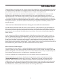
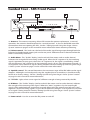
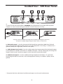
Table of Contents
Introduction. . . . . . . . . . . . . . . . . . . . . . . . . . . . . . . . . . . . . . . . . . 1
Guided Tour - SR5 Front Panel. . . . . . . . . . . . . . . . . . . . . . . . . 2
Guided Tour - SR5 Rear Panel. . . . . . . . . . . . . . . . . . . . . . . . . . 3
Guided Tour - HT5. . . . . . . . . . . . . . . . . . . . . . . . . . . . . . . . . . . . . 4
Setting Up and Using Your Stage 5 Series System. . . . . 5 - 6
Specifications. . . . . . . . . . . . . . . . . . . . . . . . . . . . . . . . . . . . . . . . . 8
Copyright 2005 - 2007, Samson Technologies Corp.
Printed October, 2007 v1.0
Samson Technologies Corp.
45 Gilpin Avenue
Hauppauge, New York 11788-8816
Phone: 1-800-3-SAMSON (1-800-372-6766)
Fax: 631-784-2201
www.samsontech.com
Introduction
Congratulations on purchasing the Samson Stage 5 Series Wireless System! Although this product
is designed for easy operation, we suggest you first take some time to go through these pages so
you can fully understand how we’ve implemented a number of unique features.
Every wireless system consists of at least two components—a transmitter and a receiver, both
of which must be tuned to the same channel (that is, the same radio frequency) in order to
operate correctly.* The Samson Stage 5 Series system you have purchased operates in the 174.6
- 213.2 MHz frequency range and contains a SR5 receiver as well as a HT5 hand-held microphone
transmitter. The HT5 hand-held microphone transmitter is equipped with the Samson H5 dynamic
microphone element, and thanks to the unidirectional pick up pattern, feedback problems are
greatly reduced.
* Your receiver and transmitter have been factory preset to utilize the same channel.
The SR5 receiver provided with the STAGE 5 Series wireless system utilizes crystal controlled, PLL
(Phase Lock Loop), Single Conversion Superheterodyne circuity for clear and reliable reception.
The antenna has been specially designed and tuned for the specified frequency band. Finally, the
provision of a noise reduction circuit produces crystal-clear sound with minimized background
noise and hiss.
In this manual, you’ll find a detailed description of the features of your Stage 5 Series system, as
well as a guided tour through all components, step-by-step instructions for setting up and using
your system and full specifications. If your Stage 5 Series system was purchased in the United
States, you’ll also find a warranty card enclosed—don’t forget to fill it out and mail it! This will
enable you to receive online technical support and will allow us to send you updated information
about other Samson products in the future. If your Stage 5 Series system was purchased outside of
the United States, please contact your local distributor for warranty details.
About Samson Technologies
Samson began 26 years ago as an audio technology company designing wireless microphone
systems. Today, we are an industry leader with three brands: Samson, Hartke and Zoom. Over 350
products designed and distributed by Samson are sold in 106 countries. They are preferred by the
most talented recording artists and performers throughout the world.
To see our complete line of audio products, visit us on the web at www.samsontech.com.
SPECIAL NOTE for U.S. purchasers: Should your Stage 5 Series system ever require servicing,
a Return Authorization number (RA) is necessary. Without this number, the unit will not be
accepted. Please call Samson at 1-800-372-6766 for a Return Authorization number prior to
shipping your unit. Please retain the original packing materials and, if possible, return the unit in
its original carton and packing materials. If your Stage 5 Series system was purchased outside of
the United States, contact your local distributor for servicing information.
Guided Tour - SR5 Front Panel
1: Antenna - The antenna mounting allows full rotation for optimum placement. In normal
operation, the antenna should be placed in a vertical position. It also can be folded inward for
convenience when transporting the SR5. See the “Setting Up and Using Your Stage 5 Series
System” section on page 5 in this manual for more information about antenna positioning.
2: Volume control - This knob sets the level of the audio signal being output through both the
balanced and unbalanced output jacks on the rear panel. Reference level is obtained when the
knob is turned fully clockwise.
3: Audio Meter - This “ladder” display (similar to the VU bar meter used on audio devices)
indicates the strength of the incoming audio signal. When the “0” segment is lit, the incoming
signal is optimized at unity gain; when the “+6” segment is lit, the signal is overloading. When
only the left-most “-20” segment is lit, the incoming signal is at just 10% of optimum strength. If
no segments are lit, little or no signal is being received. See the “Setting Up and Using Your Stage
5 Series System” section on page 5 in this manual for more information.
4: Squelch control - This control determines the maximum range of the SR5 before audio signal
dropout. Although it can be adjusted using the supplied plastic screwdriver, it should normally
be left at its factory setting. See the “Setting Up and Using Your Stage 5 Series System” section
on page 5 in this manual for more information.
5: “TX” LED - Lights when carrier signal of sufficient strength is being received by the SR5.
6: RF Meter - This “ladder” display (similar to the VU bar meter used on audio devices) indicates
the strength of the incoming radio signal. When the “100%” segment is lit, the incoming RF
signal is fully modulated and at optimum strength. When only the second most left-most “10%”
segment is lit, the incoming signal is at just 10% of optimum strength. If no segments are lit, little
or no signal is being received. See the “Setting Up and Using Your Stage 5 Series System” section
on page 5 in this manual for more information.
7: Power switch - Use this to turn the SR5 power on and off.
Guided Tour - SR5 Rear Panel
1: DC input - Connect the supplied 12 volt, 500 mA power adapter here, using the strain relief
as shown in the illustration below. WARNING: The substitution of any other kind of power
adapter can cause severe damage to the SR5 and will void your warranty.
Using the strain relief: Gather up a loop of wire and pass it through the strain relief,
then pass the adapter plug through the loop in order to create a knot.
2: Balanced output* - Use this electronically balanced low impedance (600 Ohm) XLR jack
when connecting the SR5 to professional (+4) audio equipment. Pin wiring is as follows: Pin 1
ground (shield), Pin 2 high (hot), and Pin 3 low (cold).
3: Audio Output Level switch - Sets the audio output level attenuation of the balanced output
(see #2 above) to -20 dBm (line level) or -40 dBm (mic level). See the “Setting Up and Using Your
Stage 5 Series System” section on page 5 in this manual for more information.
4: Unbalanced output* - Use this unbalanced high impedance (5K Ohm) 1/4" jack when
connecting the SR5 to consumer (-10) audio equipment. Wiring is as follows: tip hot, sleeve
ground.
* If required, both the unbalanced and balanced outputs can be used simultaneously.
Guided Tour - HT5
1: Audio on-off switch - When set to the “on”
position, audio signal is transmitted. When set to
the “off” position, the audio signal is muted. Because
the carrier signal remains during muting, no “pop” or
“thud” will be heard. Note that turning this off does
not turn off the transmitter power—it is simply a
way to temporarily mute the transmission of audio
signal. If you don’t plan on using the HT5 for extended
periods, turn off its power by using the power on-off
switch (see #3 below).
2: Battery level meter - This set of three multicolor
LEDs indicates relative battery power, indicating
whether the installed battery is at low (red), mid
(yellow) or high (green) strength. One or more of
these will light whenever the HT5 is powered on (see
#3 below). When all three are lit, the battery is at
maximum strength. When only the red “low” indicator
lights, RF performance is degraded and the battery
needs to be replaced.
3: Power on-off switch* - Use this to turn the HT5 on
or off (to conserve battery power, be sure to leave it off
when not in use).
4: Gain control (trimpot) - This input sensitivity
control has been factory preset to provide optimum
level for the particular microphone capsule provided with your Stage 5 Series system and so we
recommend that this not be adjusted manually. If necessary, however, you can use the supplied
plastic screwdriver to raise or lower the input level. See the “Setting Up and Using Your Stage
5 Series System” section on page 5 in this manual for more information.
5: Battery holder - Insert a standard 9-volt alkaline battery here, being sure to observe the
plus and minus polarity markings shown. We recommend the Duracell MN 1604 type battery.
Although rechargeable Ni-Cad batteries can be used, they do not supply adequate current for
more than four hours. WARNING: Do not insert the battery backwards; doing so can cause severe
damage to the HT5 and will void your warranty.
* Be sure to mute the audio signal at your external mixer or amplifier before turning transmitter power
on or off, or an audible pop may result.
Setting Up and Using Your
Stage 5 Series System
The basic procedure for setting up and using your Stage 5 Series Wireless System takes only a
few minutes:
1. For the Stage 5 Series system to work correctly, both the receiver and transmitter must be set
to the same channel. Remove all packing materials (save them in case of need for future service)
and check to make sure that the supplied receiver and transmitter are set to the same channel.
If these channels do not match, contact your Samson Technical Support at 1-800-372-6766.
2. Physically place the receiver where it will be used (the general rule of thumb is to maintain
“line of sight” between the receiver and transmitter so that the person using or wearing the
transmitter can see the receiver). ‑ Extend the antenna and place it in a vertical position.
3. Make sure the Power on-off switch in your HT5 handheld transmitter is set to “Off.”
4. On the HT5 handheld transmitter, unscrew the bottom section of the microphone by turning
it counterclockwise and then slide it off.
5. Place a fresh 9-volt alkaline battery in the transmitter battery holder, taking care to observe
the polarity markings. Replace the bottom section of the HT5 handheld microphone by sliding
it on and then screwing it back on. Leave the transmitter off for the moment.
6. Make the physical cable connection between the SR5 output jack and the line audio input of
your amplifier or mixer using the included 1/4-inch cable. If you are connecting to a professional
mixer you can use the balanced XLR jack (with an optional XLR mic cable), be sure to set the
receiver rear panel Audio Output Level switch correctly. If required, both the balanced and
unbalanced outputs can be used simultaneously. Leave your amplifier (and/or mixer) off at this
time.
7. Turn the Volume knob on the SR5 completely counterclockwise. Using the strain relief,
connect the supplied AC adapter to the DC Input on the rear panel of the SR5, then plug the
adapter into any standard AC outlet. Press the front panel Power switch to turn on the SR5; the
green “Power” LED will light up, but all other front panel LEDs will remain unlit
8. Turn on the power to the HT5 transmitter (using its Power on-off switch); all three Battery
strength LEDs will light if the battery is sufficiently strong. At this point, the RF Meter on the
front panel of the receiver will light.
9. Now it’s time to set the audio levels. Turn on your connected amplifier and/or mixer but
keep its volume all the way down. Next, make sure that your HT5 transmitter is unmuted by
setting its Audio switch to “On.” Then set the Volume knob on the SR5 fully counterclockwise.
Speak or sing into the mic at a normal performance level while observing the SR5 front panel
Audio Meter. If the “0” (unity gain) segment is lighting steadily, with just occasional higher
excursions, the audio level is correctly set. If not, use the supplied plastic screwdriver to slowly
adjust the HT5 Gain control (trimpot) until the SR5 Audio Meter “0” (unity gain) segment lights
steadily (with occasional higher excursions). Then slowly raise the SR5 Volume knob to the 2
o’clock position (unity gain) and, finally, set the volume of your amplifier/mixer until the desired
level is reached.
Bear in mind also that the HT5H microphone is unidirectional which means it picks up sound
from the front of the mic and rejects sound from the rear. This will help reduce the chance of
feedback. In general, you can avoid feedback by taking care not to use any microphone directly
in front of a PA speaker (if this is unavoidable, try using an equalizer to attenuate those high- or
mid-range frequencies which are causing the feedback “squealing”).
10. If you hear distortion at the desired volume level (or if the “+6” segment LED in the
Audio Meter is lighting frequently), first check that the SR5 rear panel Audio Output Level switch
is set correctly. Next, make sure that the gain structure of your audio system is correctly set
Setting Up and Using Your
Stage 5 Series System
(consult the owners manual of your mixer and/or amplifier for details). If you still hear distortion,
do the following:
•The HT5 transmitter's Gain control has been factory preset to provide optimum level for the
particular microphone model being used and so no adjustment should be necessary. Any
distortion present should therefore simply be a matter of the microphone being too close to
the mouth; try moving it further away. If this does not solve the problem, use the supplied
plastic screwdriver to turn the Gain control (trimpot) on the HT5 slowly counterclockwise until
the distortion disappears.
Note that, following this setup procedure, you can always lower the Volume knob of the SR5 in
order to further attenuate the output signal if necessary.
11. Conversely, if you hear a weak, noisy signal at the desired volume level (and with the Volume
control of the receiver turned fully clockwise), again make sure that the SR5 rear panel Audio
Output Level switch is set correctly and that the gain structure of your audio system is correctly
set. If it is and the signal coming from the SR5 is still weak and/or noisy, do the following:
•The HT5 transmitter's Gain control has been factory preset to provide optimum level for the
particular microphone model being used and so no adjustment should be necessary. Any
weakness of signal should therefore simply be a matter of the microphone being too far from
the mouth; try moving it closer. If this does not solve the problem, use the supplied plastic
screwdriver to turn the Gain control (trimpot) on the HT5 slowly clockwise until the signal
reaches an acceptable level.
12. Temporarily turn down the level of your mixer/amplifier system and turn off the power to
your transmitter, leaving the SR5 on. Then restore the previously set level of your mixer/amplifier.
With the transmitter off, the receiver output should be totally silent—if it is, skip ahead to the
next step. If it isn’t (that is, if you hear some noise), you may need to adjust the receiver’s front
panel Squelch control. When the Squelch control is at its minimum setting, the Stage 5 Series
system always provides maximum range without dropout; however, depending upon the
particular environment your system is used in, you may need to reduce that range somewhat in
order to eliminate band noise or interference when the transmitter is turned off. To do so, use
the provided screwdriver to rotate the Squelch control completely counterclockwise (to the “Min”
position), then slowly turn it clockwise until the noise disappears. If no noise is present at any
position, leave it at its fully counterclockwise “Min” position (so as to have the greatest overall
range available).
13. When first setting up the Stage 5 Series System in a new environment, it’s always a good idea
to do a walkaround in order to make sure that coverage is provided for your entire performance
area. Accordingly, turn down the level of your audio system and turn on both the transmitter
and receiver. Then, with the transmitter unmuted, restore the level of your audio system and
while speaking or singing, walk through the entire area that will need to be covered. As you do
so, the “TX” LED on the front panel of the SR5 should always remain lit. Always try to minimize
the distance between transmitter and receiver as much as possible so that the strongest
possible signal is received from all planned transmission points. In fixed installations such as
A/V or corporate conference rooms or for extended range applications (where the transmitter
and receiver are more than 150 feet apart), it may be desirable to angle the receiver antenna
differently from its vertical position or to install the receiver in the same room as the transmitters
(and, if necessary, to extend the wiring to remote audio equipment).
If you have followed all the steps above and are experiencing difficulties, contact your local
distributor or, if purchased in the United States, call Samson Technical Support (1-800-372-6766)
between 9 AM and 5 PM EST.
Specifications
Transmitter HT5
Transmission Mode
Frequency Range
OSC System
RF Power
Operating Range
Frequency Stability
Approvals
Radiating Harmonic and Spurious Emission
Antenna Type
Audio Frequency Response
Pre-Emphasis
Noise Reduction System
Signal To Noise Ratio
Maximum Input Level
T.H.D.
Current Consumption
Battery Life (MN1604 9-volt alkaline)
Operating Temperature
Controls
LED Indicator
Dimensions
Weight
Frequency modulation, 80KF3E, 15 kHz peak deviation
173.80 MHz to 213.20 MHz, 25 frequencies
Crystal controlled, x12 multiplication
20 mW (USA models), 10 mW [(2 mW ERP) European / UK models)]
300 ft.
± 10 ppm
Complies with ETS 300 422 and FCC Part 74
Below limits of applicable regulations
Internal
40 Hz to 15 kHz ±3 dB
50 µSec
NE571 based compandor
> 100 dB
0 dBv (ST5), -20 dBv (VH3)
< 1% @ 1 kHz
34 mA (typical)
6 hours (typical)
-10 to +55 degrees C
Power On/Off, Audio On/Off, Level Control (Trimpot)
Battery high/medium/low
37 (W) x 233 (H) mm (1.46 x 9.17 in.)
200 grams • 7.1 oz.
SR5 Reciever :
Receiving System
Frequency Range
Band A (European / UK models)
Band B (European / UK models)
Receiving Mode
Sensitivity
Selectivity
Squelch Sensitivity
Intermediate Frequency
Local Oscillator System
Noise Reduction System
De-emphasis
Signal To Noise Ratio
Audio Frequency Response
T.H.D.
Audio Output Levels
Audio Output Impedance
Antennas
Operating Temperature
Controls
LED Indicators
SR5
Power Requirement
Dimensions (W x H x D, without antenna)
Weight (including antenna)
Single conversion Superheterodyne
173.80 MHz to 213.20 MHz, 25 frequencies
160.10 to 177.90 MHz
189.10 to 210.10 MHz
80KF3E
< 3 µV for 20 dB SINAD, < 10 µV for 50 dB S/N
120 kHz BW, nominal @ -6 dB, ± 300 kHz (adj CH), -75 dB
3 µV to 250 µV adjustable
10.7 MHz
Crystal controlled
NE571 based compandor
50 µsec.
> 100 dB (IHF-A) line out, > 90 dB (IHF-A), mic out
40 Hz to 15 kHz ±3 dB
< 1% @ 1 kHz
-10dB unbalanced (1/4" phone connector),
-20 dBm / -40 dBm balanced (XLR connector)
5 kΩ unbalanced, 600 Ω balanced
1/4 wavelength telescopic
-10 to +55 degrees C
Volume, Squelch, Power
TX On / AF Level (6 LEDs) / RF Level (6 LEDs)
12 Volts DC, 100 mA typical (110 mA max.), AC adapter supplied
216 x 44 x 116 mm (8.5 x 1.75 x 4.6 in.)
20 g • 0.75 lb
Specifications are subject to change without notice.
--"
3 AMS ON 4ECHNOLOGIES # OR P 5NDERHILL " LVD 3 YOS S ET .9 Declaration of Conformity
Date of issue: 10/07/2004
Equipment: Wireless Microphone System
Model #: Receivers: SR5, SR55 Transmitters: HT5, ST5
Class: Samson Stage 5 and 55 Series - 174MHz to 216MHz
Manufacturer:
Address:
SAMSON TECHNOLOGIES CORPORATION
575 Underhill Boulevard, Syosset, New York 11791 USA
This is to certify that the aforementioned equipment is in conformity with the essential requirements
and other relevant requirements of the R&TTE Directive (1999/5/EC)
Applicable Standards
EN 60065:2002
EN 301489-9 v1.2.1 (2000-08)
EN 300 422-2 V1.2.2
Title
Audio, video and similar electronic apparatus - Safety requirements
Electromagnetic compatability and Radio spectrum Matters;(ERM) - Part 9:
Specific conditions for wireless microphones
Electromagnetic compatibility and Radio spectrum Matters (ERM);
Wireless microphones in the 25 MHz to 3 GHz frequency range; Part 2:
Harmonized EN under article 3.2 of the R&TTE Directive. Notified Body not
required.
Signed on behalf of the manufacturer:
Name:
Title:
Signed on behalf of the representative:
Name:
Title:
Address:
Address:
Douglas Bryant
President
4UBHF8JSFMFTT.JDSPQIPOF4ZTUFNT
$PVOUSZ$PEF
'SFRVFODZ3BOHF
$PEFEF1BZT
#BOEFEF'SÏRVFODFT"VUPSJTÏF
-BFOEFS,VF[FM
'SFRVFO[CFSFJDI
%&&4*564
o.)[
'3
.)[
(#
.)[
#&
.)[
/.)[
"MMPUIFSDPVOUSJFT
1MFBTFDPOUBDUZPVSOBUJPOBMGSFRVFODZBVUIPSJUZGPSJOGPSNBUJPOPO
BWBJMBCMFMFHBMGSFRVFODJFTBOEMFHBMVTFJOZPVSBSFB
FCC Rules and Regulations
Samson wireless systems are type accepted under FCC
rules parts 90, 74 and 15.
Licensing of Samson equipment is the user’s responsibility and licensability depends on the user’s classification,
application and frequency selected.
This device complies with RSS-210 of
Industry & Science Canada.
Operation is subject to the following two conditions:
(1) this device may not cause harmful interference and (2)
this device must accept any interference received, including interference that may cause
undesired operation.
Samson Technologies Corp.
45 Gilpin Avenue
Hauppauge, New York 11788-8816
Phone: 1-800-3-SAMSON (1-800-372-6766)
Fax: 631-784-2201
www.samsontech.com
Stage5H_om_ v1