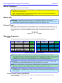
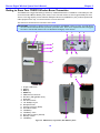
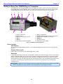
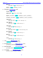
1
Zaxcom Digital Wireless System Transmitter User‟s Manual TRX900 TRX900AA TRX900LT TRX800 TRX700 TRX992 Updated: 2010-10-01 - 15:09 230 West Parkway, Unit 9, Pompton Plains, NJ 07444 USA Tel: 973-835-5000 Fax: 973-835-6633 Email: [email protected] Website: www.zaxcom.com NOTE: All specifications in this manual are subject to change without notice. Maintained by: Ray M. Owen, PSM interstage Phistersvej 31, 2900 Hellerup, Danmark Telefon 3946 0000, fax 3946 0040 www.interstage.dk - pro audio with a smile __________________________________________Zaxcom Digital Wireless System User’s Manual Consumer Alert Most users do not need a license to operate a wireless microphone system. Nevertheless, operating a microphone system without a license is subject to certain restrictions: the system may not cause harmful interference, it must operate at a low power level (not in excess of 50 milliwatts), it has no protection from interference received from any other device. Purchasers should also be aware that the FCC is currently evaluating the use of wireless microphone systems, and these rules are subject to change. For more information, call the FCC at 1-888-CALL-FCC (TTY: 1-888-TELL-FCC) or visit the FCC‟s wireless microphone website at: www.fcc.gov/cgb/wirelessmicrophones. To operate wireless microphone systems transmitting with greater than 50mW of radiated power, you must qualify as a Part 74 user and be licensed. NOTE: This alert does NOT apply to Part 74 users. 2 Zaxcom Digital Wireless System User’s Manual__________________________________________ Table of Contents CONSUMER ALERT ................................................................................................................................................................................................ 2 TABLE OF FIGURES ............................................................................................................................................... 6 TABLE OF TABLES ................................................................................................................................................ 7 CHAPTER 1 – TOPICS THAT APPLY TO MOST UNITS IN THE SYSTEM .................................................... 8 USER MANUAL CONVENTIONS........................................................................................................................................................................... 8 SYSTEM FEATURES ................................................................................................................................................................................................. 8 TRANSCEIVERS (TXS WITH IFB, TIMECODE AND REMOTE CONTROL CAPABLE RECEIVERS) .................................................................... 9 What’s included with the TRX900 ( / AA / L) ............................................................................................................................................................. 9 Options TRX900 ( / AA)................................................................................................................................................................................................. 9 What’s included with the TRX992.................................................................................................................................................................................... 9 Options.................................................................................................................................................................................................................................. 9 TRANSMITTERS ONLY......................................................................................................................................................................................... 10 What’s included with the TRX700................................................................................................................................................................................. 10 Options................................................................................................................................................................................................................................ 10 What’s included with the TRX800................................................................................................................................................................................. 10 Options................................................................................................................................................................................................................................ 10 MENU SYSTEM ..................................................................................................................................................................................................... 10 MEDIA ................................................................................................................................................................................................................... 11 MICROPHONES .................................................................................................................................................................................................... 12 Compatible Lavs .................................................................................................................................................................................................................... 12 Compatible Stick Mics ........................................................................................................................................................................................................ 12 General..................................................................................................................................................................................................................................... 12 BATTERY INSTALLATION .................................................................................................................................................................................... 13 BATTERY LIFE ....................................................................................................................................................................................................... 13 EXTERNAL POWER.............................................................................................................................................................................................. 13 OPERATING FREQUENCIES ................................................................................................................................................................................. 13 Audio ......................................................................................................................................................................................................................................... 13 Remote Control, Timecode and IFB Feed ..................................................................................................................................................................... 13 ANTENNA CABLE SELECTION ........................................................................................................................................................................... 14 PRODUCT SUPPORT............................................................................................................................................................................................ 14 CHAPTER 2 – DIGITAL WIRELESS SYSTEM TRANSMITTERS ..................................................................... 15 GETTING TO KNOW YOUR TRX900 ( / AA / L) BODYPACK TRANSMITTER........................................................................................... 15 Device Interface .................................................................................................................................................................................................................... 17 Media Slot ........................................................................................................................................................................................................................... 17 Unit Power Switch – Internal/External Power Switch ........................................................................................................................................... 17 UHF Antenna ..................................................................................................................................................................................................................... 17 IFB Antenna ........................................................................................................................................................................................................................ 17 RECORD key (TRX900 (L) Only) .............................................................................................................................................................................. 17 PLAY key (TRX900 (L) Only) ...................................................................................................................................................................................... 17 STOP key (TRX900 (L) Only) ..................................................................................................................................................................................... 17 INC key ............................................................................................................................................................................................................................... 17 DEC key .............................................................................................................................................................................................................................. 17 TRX900 ( / AA / L) Configuration Menus .................................................................................................................................................................. 18 GETTING TO KNOW YOUR TRX992 WIRELESS BOOM TRANSMITTER ..................................................................................................... 19 Device Interface .................................................................................................................................................................................................................... 20 Media Slot ........................................................................................................................................................................................................................... 20 Unit Power Switch ........................................................................................................................................................................................................... 20 UHF Antenna ..................................................................................................................................................................................................................... 20 IFB Antennas ...................................................................................................................................................................................................................... 20 Mix Ratio knob .................................................................................................................................................................................................................. 20 Headphone Fader knob .................................................................................................................................................................................................. 20 Battery Slot......................................................................................................................................................................................................................... 20 INC key ............................................................................................................................................................................................................................... 20 DEC key .............................................................................................................................................................................................................................. 20 Phantom Power Switch & Mic/Line Switch ............................................................................................................................................................... 21 3 __________________________________________Zaxcom Digital Wireless System User’s Manual TRX992 Configuration Menus......................................................................................................................................................................................... 22 GETTING TO KNOW YOUR TRX700 PLUG-ON TRANSMITTER .................................................................................................................. 23 Device Interface .................................................................................................................................................................................................................... 23 UHF Antenna ..................................................................................................................................................................................................................... 23 Phantom Power switch ................................................................................................................................................................................................... 23 Media Slot ........................................................................................................................................................................................................................... 23 TRX700 Configuration Menus......................................................................................................................................................................................... 24 GETTING TO KNOW YOUR TRX800 HANDHELD WIRELESS TRANSMITTER ............................................................................................ 25 Device Interface .................................................................................................................................................................................................................... 26 Media Slot ........................................................................................................................................................................................................................... 26 Unit Power Switch ........................................................................................................................................................................................................... 26 UHF Antenna ..................................................................................................................................................................................................................... 26 RECORD key..................................................................................................................................................................................................................... 26 TRX800 Configuration Menus......................................................................................................................................................................................... 26 TRANSMITTER BOOTUP SEQUENCES ................................................................................................................................................................ 27 Standard Bootup Sequence (without any card inserted) ......................................................................................................................................... 27 Standard Bootup Sequence (with a formatted card inserted) ............................................................................................................................... 28 Extended Menu Bootup Sequence (without any card inserted)............................................................................................................................ 29 Extended Menu Bootup Sequence (with a formatted card inserted) ................................................................................................................. 30 COMMON TRANSMITTER STANDARD MENU .................................................................................................................................................. 31 Pacifier page ........................................................................................................................................................................................................................... 31 Audio Gain page ................................................................................................................................................................................................................... 32 UHF Freq page ...................................................................................................................................................................................................................... 32 Transport Control page (requires RECORDING OPTION) ................................................................................................................................... 33 TC Frame-rate page (requires RECORDING OPTION) ......................................................................................................................................... 33 Earpiece Source page (requires IFB AUDIO OPTION) (TRX9xx ONLY) ........................................................................................................ 33 Lock page ................................................................................................................................................................................................................................ 34 Unlocking the Unit ........................................................................................................................................................................................................... 34 COMMON TRANSMITTER EXTENDED MENU................................................................................................................................................... 34 Entering the Extended Menu ........................................................................................................................................................................................... 34 Exiting the Extended Menu ............................................................................................................................................................................................... 34 Highpass Filter page ............................................................................................................................................................................................................ 34 Limiter page ........................................................................................................................................................................................................................... 35 1K Notch Filter Enable page (requires enabled IFB Audio Option) ................................................................................................................... 35 1K Notch Filter Freq page (requires enabled IFB Audio Option) ........................................................................................................................ 35 UHF Signal Format page ................................................................................................................................................................................................... 36 IFB Signal Format page (requires IFB AUDIO OPTION) (TRX9xx ONLY) ..................................................................................................... 36 IFB RX Enable page ............................................................................................................................................................................................................ 36 IFB Voting Enable page....................................................................................................................................................................................................... 37 IFB Freq page ......................................................................................................................................................................................................................... 37 IFB Dropout Compensator page (requires enabled IFB Audio Option) ............................................................................................................. 37 Power-up Mode page .......................................................................................................................................................................................................... 37 Unlocking the Unit ........................................................................................................................................................................................................... 38 Format Recording Card page............................................................................................................................................................................................ 38 To Format a Card: ........................................................................................................................................................................................................... 38 To Recreate the Wrapper Files (will not destroy existing audio takes):.......................................................................................................... 38 TC Jam Mode page.............................................................................................................................................................................................................. 39 TC Source page ..................................................................................................................................................................................................................... 39 TC Output Enable page ..................................................................................................................................................................................................... 39 Group ID page....................................................................................................................................................................................................................... 39 Unit ID page........................................................................................................................................................................................................................... 40 Expander page ...................................................................................................................................................................................................................... 40 Dynamics page (ADVANCED USERS ONLY!)........................................................................................................................................................... 40 ADC Select page ................................................................................................................................................................................................................... 41 Battery Type page ................................................................................................................................................................................................................ 41 Recording Mode page (requires RECORDING OPTION) ...................................................................................................................................... 42 UHF TX Power page ........................................................................................................................................................................................................... 42 Boot Up Mode page ............................................................................................................................................................................................................ 42 Mute Switch Enable page (TRX900 ( / AA) ONLY) .............................................................................................................................................. 42 Private Line Key Assignment page .................................................................................................................................................................................. 43 4 Zaxcom Digital Wireless System User’s Manual__________________________________________ Side Tone Gain page (requires enabled IFB Audio Option) .................................................................................................................................. 43 Allow IFB Remote Control page ....................................................................................................................................................................................... 43 IFB Jam Threshold page ..................................................................................................................................................................................................... 44 Send QRX Program page .................................................................................................................................................................................................. 44 Track Name page ................................................................................................................................................................................................................ 44 Encryption Code page ......................................................................................................................................................................................................... 44 CHAPTER 3 – RECORDING AUDIO USING THE DIGITAL WIRELESS SYSTEM TRANSMITTERS ........ 46 RECORDING FORMAT......................................................................................................................................................................................... 46 RECORDING MODE ............................................................................................................................................................................................ 46 BATTERY LIFE ....................................................................................................................................................................................................... 46 MEDIA CAPACITY ................................................................................................................................................................................................ 46 DUAL COLOR LED............................................................................................................................................................................................. 47 RECORDING OPERATION .................................................................................................................................................................................. 47 Formatting the Media Card .............................................................................................................................................................................................. 47 Current Timecode and Frame-rate Display ................................................................................................................................................................. 47 Jamming Timecode into the Unit..................................................................................................................................................................................... 47 Manually Jamming TC with a Cable ............................................................................................................................................................................. 48 Continuously Jamming TC using the IFB100............................................................................................................................................................. 48 Automatically Starting and Stopping the Recording using Timecode from the IFB100 ................................................................................ 48 CHAPTER 4 – TRX900 ( / AA) ADAPTERS ....................................................................................................... 49 STA100 STEREO ADAPTER................................................................................................................................................................................ 49 Installation ............................................................................................................................................................................................................................... 49 Adjusting the Input Level .................................................................................................................................................................................................... 49 Powering the STAxxx ........................................................................................................................................................................................................... 50 Using an External Power Source .................................................................................................................................................................................. 50 Using the STAxxx to Power the Unit......................................................................................................................................................................... 50 The Audio/Timecode Output Connection ..................................................................................................................................................................... 50 Timecode Input ................................................................................................................................................................................................................. 50 Operation of the STAxxx .............................................................................................................................................................................................. 50 Host Unit functions .......................................................................................................................................................................................................... 50 STA150 STEREO ADAPTER................................................................................................................................................................................ 51 EA100 EARPIECE ADAPTER ............................................................................................................................................................................... 51 TCA100 TIMECODE ADAPTER ......................................................................................................................................................................... 52 MSA100 MUTE SWITCH .................................................................................................................................................................................... 52 CHAPTER 5 – NEW SYSTEM CAPABILITIES ................................................................................................... 53 INTRODUCTION .................................................................................................................................................................................................. 53 SUPER LOW POWER STANDBY MODE ......................................................................................................................................................... 53 IMPROVED TIMECODE SYNC .............................................................................................................................................................................. 53 “SAFE BOOT” MODE ........................................................................................................................................................................................... 54 USING REMOTE CONTROL AND TIMECODE WHILE IN HQ MODE ............................................................................................................. 54 USING HIGH CAPACITY SD CARDS ................................................................................................................................................................. 54 NEW IFB HIGH QUALITY MODE IN TRX992 ................................................................................................................................................ 54 INDEPENDENT TRX992 FIRMWARE VERSION ................................................................................................................................................. 54 LEFT/RIGHT SWITCH MODE .............................................................................................................................................................................. 54 NEW IFB AUDIO CODEC .................................................................................................................................................................................. 55 CHAPTER 6 – ZAXCONVERT UTILITY ............................................................................................................ 56 ABOUT ZAXCONVERT....................................................................................................................................................................................... 56 USING ZAXCONVERT ........................................................................................................................................................................................ 56 OUTPUT FILE TYPE.............................................................................................................................................................................................. 56 TIMECODE ............................................................................................................................................................................................................ 57 SAMPLE-RATE CONVERSION ............................................................................................................................................................................. 57 MAXIMUM FILE SIZE ............................................................................................................................................................................................ 57 OUTPUT FILE NAME ........................................................................................................................................................................................... 57 TRACK ENABLE.................................................................................................................................................................................................... 57 CHAPTER 7 – EQUIPMENT SPECIFICATIONS ............................................................................................... 58 5 __________________________________________Zaxcom Digital Wireless System User’s Manual TRX900 ( / AA / L) SPECIFICATIONS.............................................................................................................................................................. 58 TRX992 SPECIFICATIONS .................................................................................................................................................................................. 60 TRX700 SPECIFICATIONS .................................................................................................................................................................................. 61 TRX800 SPECIFICATIONS .................................................................................................................................................................................. 62 CHAPTER 8 – WIRING DIAGRAMS ................................................................................................................... 63 TRX900 ( / AA / L) MICROPHONE CABLES (AFTER SERIAL # 1314) .......................................................................................................... 63 TRX900 ( / AA) MICROPHONE CABLES (BEFORE SERIAL # 1315) ............................................................................................................. 64 STAXXX AND IFB100 CABLES ......................................................................................................................................................................... 65 TRX700 JAM SYNC CABLE ................................................................................................................................................................................ 65 CHAPTER 9 – FIRMWARE INFORMATION ...................................................................................................... 66 FIRMWARE ............................................................................................................................................................................................................ 66 Advantages to Upgrading the Firmware ....................................................................................................................................................................... 66 Upgrading the Firmware in each TRX series unit ..................................................................................................................................................... 67 KNOW FIRMWARE ISSUES .................................................................................................................................................................................. 68 TRX / ZFR / IFB FIRMWARE HISTORY............................................................................................................................................................. 69 CHAPTER 10 – MENU SHEETS........................................................................................................................... 74 MENU SHEET FOR TRX9XX .............................................................................................................................................................................. 74 MENU SHEET FOR TRX700 / TRX800 ............................................................................................................................................................ 79 CHAPTER 11 – DIGITAL WIRELESS SYSTEM QUICKSTART ....................................................................... 82 COMMON SETTINGS FOR ASSOCIATED TRANSMITTERS, RECEIVERS AND IFB ............................................................................................ 82 USING YOUR WIRELESS TRANSMITTERS AND RECEIVERS .............................................................................................................................. 82 Receiver Related Preparation............................................................................................................................................................................................ 82 Scan for an Open UHF Frequency ............................................................................................................................................................................... 82 Set the UHF Signal Format (Not Required for QRX100) ................................................................................................................................... 83 Enter the Encryption Code (Not Required for QRX100) .................................................................................................................................. 83 Transmitter Related Preparation ..................................................................................................................................................................................... 83 Power Switch ..................................................................................................................................................................................................................... 83 Enter the UHF Transmitter Frequency ...................................................................................................................................................................... 83 Set the UHF Signal Format (TRX900 ( / AA) w/ STAxxx) .................................................................................................................................. 84 Set Where Analog to Digital Conversion is to be Performed ............................................................................................................................ 84 Set the UHF Transmitter Power (May 2008 and later models) .......................................................................................................................... 84 Enter the Encryption Code ............................................................................................................................................................................................ 84 REMOTELY CONTROLLING THE TRANSMITTERS AND SENDING IFB AUDIO .............................................................................................. 85 IFB100 Related Preparation ............................................................................................................................................................................................. 85 Enter the IFB Transmitter Frequency for Your Group ......................................................................................................................................... 85 Connect the Audio Source to the IFB transmitter ................................................................................................................................................. 85 Enter a Unique Group ID for Your Gear .................................................................................................................................................................. 85 Send Timecode from the TC Source to each Transmitter .................................................................................................................................. 85 Set the IFB Signal Format for Your Group ................................................................................................................................................................ 85 Cycle the IFB100‟s Power .............................................................................................................................................................................................. 85 TRX9xx Related Preparations .......................................................................................................................................................................................... 86 Enable the Remote Control Capability on the Unit ............................................................................................................................................... 86 Set the IFB Format ........................................................................................................................................................................................................... 86 Enable the IFB Receiver .................................................................................................................................................................................................. 86 Enter Your Gear‟s Group ID ........................................................................................................................................................................................ 86 Assign a Unique Unit ID ................................................................................................................................................................................................. 86 Select the IFB Receiver‟s Frequency ........................................................................................................................................................................... 86 Select the Earpiece Source ............................................................................................................................................................................................ 87 Cycle the Power of Your Transmitter ....................................................................................................................................................................... 87 CHAPTER 12 – ZAXCOM WARRANTY POLICY AND LIMITATIONS ......................................................... 88 Table of Figures Figure 1-1 TRX900 Keys .................................................................................................................................................................................... 10 Figure 1-2 External Power Polarity ................................................................................................................................................................. 13 Figure 2-1 TRX900AA Top, Front and Back Views .................................................................................................................................... 15 6 Zaxcom Digital Wireless System User’s Manual__________________________________________ Figure 2-2 Figure 2-3 Figure 2-4 Figure 2-5 Figure 2-6 Figure 2-7 Figure 4-1 Figure 4-2 Figure 4-3 Figure 4-4 Figure 4-5 Figure 4-6 Figure 6-1 Figure 6-2 Figure 6-3 Figure 6-4 Figure 6-5 Figure 8-1 Figure 8-2 Figure 8-3 Figure 8-4 Figure 8-5 Figure 8-6 Figure 8-7 Figure 8-8 Figure 8-9 TRX900 Top, Front and Back Views .......................................................................................................................................... 16 TRX900 (L) Top, Front and Back Views.................................................................................................................................... 16 TRX992 Front, Top, Bottom, Back & Battery Views ............................................................................................................. 19 Location of TRX992 Internal Switches ...................................................................................................................................... 21 TRX700 Front & Top End Views ................................................................................................................................................. 23 TRX800 Side, Mic Capsule, Body Threaded End, Body Antenna End & Body Side Views ........................................... 25 STA100 Front & Back Views ......................................................................................................................................................... 49 STA100 attached to TRX900AA ................................................................................................................................................. 50 STA150 & STA150 attached to TRX900AA ............................................................................................................................. 51 EA100 & EA100 attached to TRX900 ........................................................................................................................................ 51 TCA100 attached to TRX900AA & TCA100 .......................................................................................................................... 52 MSA100 Mute Switch Adapter attached to TRX900AA & MSA100 Mute Switch Adapter ......................................... 52 ZaxConvert Windows & Mac Main pages ................................................................................................................................. 56 Choose Output File Type page .................................................................................................................................................... 56 Timecode Options page ................................................................................................................................................................. 57 Output Sample Rate Conversion page ....................................................................................................................................... 57 Maximum Output File Size page .................................................................................................................................................. 57 Two-wire Microphone Configuration (Current Transmitters) ........................................................................................... 63 Three-wire Microphone Configuration (Current Transmitters) ........................................................................................ 63 Balanced Line to TRX900 ( / AA / L) ........................................................................................................................................ 63 Two-wire Microphone Configuration (Previous Transmitters) .......................................................................................... 64 Three-wire Microphone Configuration (Previous Transmitters) ........................................................................................ 64 Balanced Line to TRX900 ( / AA) .............................................................................................................................................. 64 Standard XLR-3F to TA-5F Line-level Input Cable ................................................................................................................. 65 LEMO-5M to 1/8” Male Timecode Input Cable ....................................................................................................................... 65 LEMO-5M to XLR-3M Timecode Input Cable ......................................................................................................................... 65 Table of Tables Table 1-1 Approved vs. Unapproved Media ................................................................................................................................................. 11 Table 1-2 Compatible Lavalier Microphones ................................................................................................................................................ 12 Table 1-3 Compatible Stick Microphones ..................................................................................................................................................... 12 Table 1-4 Audio Frequency Block Information ............................................................................................................................................ 13 Table 2-1 TRX900 ( / AA / L) Unit Differences.......................................................................................................................................... 15 Table 2-2 TRX900 ( / AA) Power Switch Alternate Functionality ........................................................................................................ 17 Table 2-3 TRX900 ( / AA / L) Standard & Extended Menus ................................................................................................................... 18 Table 2-4 TRX992 Standard & Extended Menus ......................................................................................................................................... 22 Table 2-5 TRX700 Standard & Extended Menus ......................................................................................................................................... 24 Table 2-6 TRX800 Standard & Extended Menus ......................................................................................................................................... 26 Table 2-7 Standard Bootup Sequence (without any card inserted) ........................................................................................................ 27 Table 2-8 Standard Bootup Sequence (with a formatted card inserted) ............................................................................................... 28 Table 2-9 Extended Menu Bootup Sequence (without any card inserted) ........................................................................................... 29 Table 2-10 Extended Menu Bootup Sequence (with a formatted card inserted)................................................................................ 30 Table 2-11 Audio Gain Valid Range and Step Size....................................................................................................................................... 32 Table 2-12 Format Error Codes ...................................................................................................................................................................... 38 Table 3-1 Available Recording Time ............................................................................................................................................................... 46 Table 3-2 Recorder LED Indications ............................................................................................................................................................... 47 Table 9-1 Software Compatibility List ............................................................................................................................................................ 66 Table 11-1 Audio Settings that Must be Consistent ................................................................................................................................... 82 Table 11-2 IFB Settings that Must be Consistent......................................................................................................................................... 82 Table 11-3 Private Channel Settings that Must be Consistent ................................................................................................................. 82 7 Chapter 1_______________________________________Zaxcom Digital Wireless System User’s Manual Chapter 1 – Topics that apply to most units in the system User Manual Conventions Throughout this manual, the following conventions are used: button – refers to an on-screen (VIRTUAL) object that represents a parameter that can be viewed and/or changed. cycle the power – refers to turning „OFF‟ the power to the unit, waiting a few seconds and then turning it back „ON‟. IFB ? – IFB followed by transmitter or frequency refers to the IFB portion of the bodypack or hand mic transmitter, or the IFB100 transmitter. key – refers to a PHYSICAL object on the unit for the Operator to change and/or view a parameter or to navigate through the menus. media card – refers to any approved card in Table 1-1 {p.11}. {p.##} – refers to the page number where the referenced item is located. starting value – refers to a value that should be used for a particular parameter and for all of the parameters when the Operator is having difficulty getting the unit to work correctly. The value is highlighted. STAxxx – refers to the STA100 and STA150. TRX900 ( / AA) – refers to the TRX900 and TRX900AA. TRX900 ( / AA / L) – refers to the TRX900, TRX900AA, TRX900LT and TRX900LTS. TRX900 (L) – refers to the TRX900LT and TRX900LTS. TRX9xx – refers to the TRX900, TRX900AA, TRX900LT, TRX900LTS and TRX992. TRXxxx – refers to the TRX900, TRX900AA, TRX900LT, TRX900LTS, TRX992, TRX800 and TRX700. UHF ? – UHF followed by transmitter or frequency refers to the UHF portion of the bodypack or hand mic transmitter NOTE: A green NOTE is a helpful hint or bit of information. IMPORTANT: A blue IMPORTANT note indicates something more important than a green NOTE. CAUTION: A yellow CAUTION note indicates a situation that, if ignored, could cause a significant problem. WARNING: A red WARNING note indicates a situation that, if ignored, could cause damage to you, your equipment and/or your reputation. System Features Superb audio quality that rivals a hardwired microphone Fault tolerant broadcast quality recording Digital modulation wireless transmission Digital drop-out protection Audio recording and transmission at 24 bits/48 kHz 96 hours of audio directly on a 16 GB removable card Supports both record/stop and continuous loop recording Backlit graphic liquid crystal display Frequency selectable highpass filter Selectable peak limiter Lightweight rugged design Integrated TC reader/generator accurate to 1 frame in 6 hours Efficient keypad for one-handed operation Integrated & encrypted IFB channel in wireless transmitter (TRX9xx) Integrated timecode reception (TRX9xx) RF remote control of TRX9xx transmitters: o Audio gain (Raise/Lower) o Recording (Start/Stop) o Transmitter power (On/Standby) 8 Zaxcom Digital Wireless System User’s Manual_______________________________________Chapter 1 o Remote frequency change Transmission delay: o US Mono mode – 3.6 ms o Euro mode – 6 ms o Stereo mode – 6 ms o ERX – 10 ms Battery runtime: o TRX700 – up to four hours @ 50 mW on two AA Lithium batteries o TRX800 – up to five hours @ 50 mW on one CR123 battery o TRX900 – up to five hours @ 50 mW on one CR123 battery o TRX900AA – up to ten hours @ 50 mW on two AA Lithium batteries o TRX900 (L) – up to five hours @ 50 mW on one AA Lithium battery o TRX992 – up to four hours @ 50 mW on one VPX battery Size and weight: (H x W x D – while looking at the screen) o TRX700 – 1.75” x 3.75” x 1.75” – 44 mm x 95 mm x 44 mm o TRX800: Body – 6.12” x 1.5” – 155 mm x 38 mm Capsule (ex.) – 3.0” x 3.0” – 76 mm x 76 mm o TRX900 – 2.3” x 2.3” x 0.65” – 58 mm x 58 mm x 17 mm o TRX900AA – 3.38” x 2.3” x 0.65” – 86 mm x 58 mm x 17 mm o TRX900 (L) – 2.5” x 2.34” x 0.69” – 63 mm x 59 mm x 17 mm o TRX992 – 5.5” x 2.9” x 1.1” – 140 mm x 74 mm x 28 mm – 6.6 oz – 187g – 8.2 oz – 4.9 oz – 4.0 oz – 4.0 oz – 3.1 oz – 13.2 oz – – – – – – 232g 139g 113g 113g 88g 374g Transceivers (TXs with IFB, Timecode and Remote Control Capable Receivers) What’s included with the TRX900 ( / AA / L) 1 – SSMA „Whip‟ Antenna 1 – media slot dust plug 1 – belt clip receive timecode and remote control signals from the optional IFB100 1 – blue Zaxcom storage/carrying case this user‟s manual on CD-ROM Options TRX900 ( / AA) TRX901 TRX10 TCA100 STA100 STA150 EA100 MSA100 TRX901 – Internal recording option – Receive audio portion of IFB100 transmission (requires EA100 or STAxxx for monitoring IFB audio) – Timecode adapter – Stereo adapter – New stereo adapter – Earpiece adapter – Mute switch – Internal recording option What’s included with the TRX992 1 – SSMA „Whip‟ Antenna 1 – media slot dust plug 1 – belt clip 1 – ZPX battery 1 – ZPX battery charger receive timecode and remote control signals from the optional IFB100 TRX10 – Receive audio portion of the IFB100 transmission TRX901 – Internal recording option 1 – blue Zaxcom storage/carrying case this user‟s manual on CD-ROM Options VPX batteries VPX battery charger ZPX batteries 9 Chapter 1_______________________________________Zaxcom Digital Wireless System User’s Manual ZPX battery charger Transmitters Only What’s included with the TRX700 1 – SMA „Whip‟ Antenna 1 – blue Zaxcom storage/carrying case this user‟s manual on CD-ROM Options TRX901 – Internal recording option What’s included with the TRX800 1 – SMA „Whip‟ Antenna 1 – blue Zaxcom storage/carrying case this user‟s manual on CD-ROM Options TRX901 – Internal recording option Shure microphone capsule(s) Menu System Figure 1-1 TRX900 Keys The user interface for each unit consists of a Liquid Crystal Display with at least the following 3 keys: MENU – Each time the MENU key is pressed, the next page/field in the current menu is displayed on the screen. INC (up arrow) – Increment the current parameter selected by the MENU key. DEC (down arrow) – Decrement the current parameter selected by the MENU key. Each menu has several pages allowing you to change configuration settings. All of these settings are stored in Flash ROM immediately after making the change. 10 Zaxcom Digital Wireless System User’s Manual_______________________________________Chapter 1 Media Most of the units read from and/or record to a MiniSD/MicroSD card, which is inserted into the media slot. All of the transmitters use a MiniSD/MicroSD card to update the unit‟s firmware. To be safe, you must use approved media: Media SanDisk 4GB SDHC MiniSD/MicroSD Transcend 4GB SDHC MiniSD/MicroSD ALL SanDisk MicroSD 4GB & Larger (with/without MiniSD adapter) Transcend 2GB (x80) MiniSD Transcend 4GB MiniSD ALL Dane-Elec SanDisk 2GB MiniSD ALL SanDisk Ultra ALL SanDisk Ultra II ALL Transcend (x45) Any brand that prints the info on a sticker applied to the chip Transcend 2GB MicroSD (no speed rating) HP 4GB SDHC MicroSD (class 4) Adata 4GB SDHC MicroSD (class 2) Manufacturer’s ID Approved? YES YES YES TS2GSDM80 TS4GSDM80 YES YES NO NO NO NO NO NO NO NO NO Table 1-1 Approved vs. Unapproved Media IMPORTANT: To use any 4GB card, V5.53 or greater is required. If unapproved media is used, it could become jammed in the media socket and damage it. CAUTION: Damage resulting from using unapproved media is not covered by the warranty. Do not use SanDisk Ultra II cards. Formatting one of them may make it unusable. We have been shipping a regular SanDisk 2GB MiniSD card (for programming purposes), and it turns out to be right on the edge of recording reliability. The symptoms involve the TRX or ZFR periodically going in to and out of record because the card holds off the processor for too long. Here is a testing procedure to determine if the card will function correctly: 1) Format the card in the Zaxcom unit. 2) Power cycle the unit. 3) Record audio to the card for several hours or more while in standalone mode (with no timecode source to prevent a re-jam event). 4) Look at the Transport Control page {p.33}. Assuming the unit did not have any external timecode applied, it should still be recording in segment #1. IMPORTANT: If you see the timecode stop (or pause), that is when the card is not accepting data. Alternatively, the Power/Record LED (where present), stays Red when the processor is waiting for the card to accept data and Green when the processor is writing to the card. If the card refuses to accept data for more than 1/2 second (a solid Red LED) the unit will stop recording to the current segment and try to start recording in the next segment. In the Pacifier page {p.31}, you may also see Rx! (x indicates the number of record errors). 11 Chapter 1_______________________________________Zaxcom Digital Wireless System User’s Manual Microphones Compatible Lavs Use one of the following microphone models: Brand Countryman Countryman Countryman Countryman DPA Sanken Sennheiser Model B6 B3 E6 omni EMW 4063-BMZ COS-11D MKE-2 Platinum Voltage 1.5 Notes 1.5 3 Specify for use with Zaxcom Use only the Zaxcom 3.3 V model Sennheiser MKE-2 Gold 3 Shure Sony Tram Voice Tech. Voice Tech Voice Tech. WL50 ECM77 TR-50 VT401HS VT506 VT910 5 3 New model – YES. Older models – NO Table 1-2 Compatible Lavalier Microphones Additional microphones will be added to this list after a review of their 3.3v power performance and RF interference susceptibility has been completed. Compatible Stick Mics Use one of the following microphone models: Brand Schoeps Sennheiser Sennheiser Sennheiser Sennheiser Model CMC6MK41 MKH 40 MKH 50 MKH 60 MKH 816 Voltage Notes Older models may pick up some RFI Table 1-3 Compatible Stick Microphones Additional microphones will be added to this list after a review of their RF interference susceptibility has been completed. General The TRX900 ( / AA / L) has an unbalanced microphone input accessed through a 3-pin micro-LEMO connector. You can use an unbalanced dynamic microphone or a powered lavaliere. It is recommended that you use 3-wire lavalieres with separate pins for ground, audio and power. When using a line-level input, an inline pad is required on the standard dynamic microphone input cable (XLR-3 to 3-pin micro-LEMO). When using a phantom powered microphone with the TRX900 ( / AA / L), you must use an external 48 VDC power supply. The TRX700 and TRX992 are the only Zaxcom transmitters that include a 48 VDC phantom power supply. NOTE: Once upon a time, the Denecke 48V power supply could damage the now discontinued Goldline transmitter‟s preamp. This is NOT the case with the TRX900 ( / AA / L). 12 Zaxcom Digital Wireless System User’s Manual_______________________________________Chapter 1 Battery Installation Each unit may require one to four batteries. CAUTION: Always observe the correct battery polarity. The negative contact on the battery is always connected to the spring contact. Never use any battery that is missing insulation on its body. If you do, it can cause a short circuit in the battery compartment, causing damage to the unit. Battery Life IMPORTANT: If operating using internal batteries, it is recommended that you use only Lithium or rechargeable NiMH. Any other battery chemistry including Alkaline and Ultra batteries have a substantially reduced runtime compared to Lithium or NiMH cells. This is true for all Zaxcom units. External Power Some of the units can be powered from an external power source. The external power connection is a 2.5 mm (0.1”) barrel connector. The center pin is positive. The connector for the receiver (Switchcraft 761K) is longer than the connector for the STAxxx and IFB100 (Switchcraft 760K). The 760K will not work in any of the receivers. Figure 1-2 External Power Polarity Operating Frequencies Audio All audio transmitters and receivers operate on one of the following frequency blocks: Block 20 21 22 23 24 25 26 Frequency Range 518.0 to 542.0 536.0 to 572.0 560.0 to 590.0 590.0 to 614.0 614.0 to 644.0 638.0 to 668.0 662.0 to 692.0 TV Channels 22 to 25 25 to 30 29 to 33 34 to 37 38 to 42 42 to 46 46 to 50 Antenna Length 5.00” 4.48” 4.24” 4.01” 3.81” 3.81” 3.62” Block 27 28 29 30 31 32 33 Frequency Range 686.0 to 722.0 722.0 to 746.0 740.0 to 770.0 764.0 to 794.0 794.0 to 818.0 818.0 to 842.0 860.0 to 872.0 TV Channels 50 to 55 56 to 59 59 to 63 63 to 67 68 to 71 72 to 75 79 to 80 Antenna Length 3.46” 3.31” 3.18” 3.08” 2.99” 2.92” 2.87” Table 1-4 Audio Frequency Block Information NOTE: Antenna length is measured from the base of the whip, where it is attached to the connector. The length of the antenna varies with the frequency block. The actual length of the antenna is not as critical as it might appear in the table. The antenna‟s usage bandwidth is +/- 50 MHz from the center frequency, so it is acceptable to use an antenna from an adjacent block above or below the operating frequency. IMPORTANT: As of 12 June 2009, the USA has phased out analog television. As a result, on 12 June 2010 frequencies between 698.0 and 806.0 MHz will no longer available for use in the USA. NOTE: As currently scheduled, on 31 August 2011, Canada will phase out analog television. As a result, on that day, frequencies between 698.0 and 806.0 MHz will no longer be available for use in Canada. IMPORTANT: Only the frequencies in one specific block are available to a particular transmitter and its associated receiver. Coordinate with your dealer or Zaxcom to determine which block(s) are the best to use in your area(s). Remote Control, Timecode and IFB Feed If the optional IFB feed and IFB remote control options are included, their worldwide frequency range is: 2.403 to 2.475 GHz 13 Chapter 1_______________________________________Zaxcom Digital Wireless System User’s Manual Antenna Cable Selection When selecting a cable, it should be as short as possible. When using standard cable, the recommendation is to not exceed 10 feet. However, if greater than 10 feet is needed, a very low loss cable should be used. For maximum performance, use only high quality 50-ohm coax cable and the absolute minimum necessary to get the job done. Otherwise, the receiver‟s sensitivity may suffer. When installing cables permanently, use ½” Andrew heliax (http://awapps.commscope.com/catalog). Using heliax cable, a run of 100 feet (~ 30.5 meters) can be achieved without significant power loss. Product Support Download the latest Firmware from: Download the latest User Manual from: Register your new Zaxcom Product at: Submit Technical Questions at: Request an RMA # at: http://www.zaxcom.com/support_software_updates.htm. http://www.zaxcom.com/support_instructional_manuals.htm. http://www.zaxcom.com/support_product_registration.htm. http://www.zaxcom.com/support_submit_tech_questions.htm. http://www.zaxcom.com/support_repair_services.htm 14 Zaxcom Digital Wireless System User’s Manual_______________________________________Chapter 2 Chapter 2 – Digital Wireless System Transmitters This chapter is intended to quickly familiarize you with the functions of each of the Digital Wireless System transmitters. Getting to Know Your TRX900 ( / AA / L) Bodypack Transmitter The TRX900, TRX900AA, TRX900LT and TRX900LTS are essentially identical in operation. The following table identifies their differences: RF Power Range Recording Media Battery(s) required Accepts Adapters IFB Audio Case TRX900 10 -50mW MiniSD / MicroSD one – CR123 Yes Yes Aluminum TRX900AA 10 – 50mW MiniSD / MicroSD two – AA Yes Yes Aluminum TRX900LT 50mW only MicroSD one – AA No No Nylon Polymer TRX900LTS 50mW only MicroSD one – AA No No Nylon Polymer Table 2-1 TRX900 ( / AA / L) Unit Differences This section was written based on firmware version 6.76. 1. 2. 3. 4. 5. 6. 7. 8. 9. 10. 11. 1. – SSMA Antenna Connector 2. – Media Slot 3. – Power/Record LED 4. – Unit Power Switch 5. – 3-pin Micro-LEMO Connector 6. – Graphic LCD Screen 7. – INC key 8. – DEC key 9. – MENU key 10. – IFB Antennas and Receiver 11. – Battery Compartment Door Figure 2-1 TRX900AA Top, Front and Back Views 15 Chapter 2_______________________________________Zaxcom Digital Wireless System User’s Manual 1. 2. 3. 4. 5. 6. 7. 8. 9. 10. 11. 1. – SSMA Antenna Connector 2. – Media Slot 3. – Power/Record LED 4. – Unit Power Switch 5. – 3-pin Micro-LEMO Connector 6. – Graphic LCD Screen 7. – INC key 8. – DEC key 9. – MENU key 10. – IFB Antennas and Receiver 11. – Battery Compartment Door Figure 2-2 TRX900 Top, Front and Back Views 1. 2. 3. 4. 5. 6. 7. 8. 9. 10. 11. 1. – SSMA Antenna Connector 2. – Unit Power Switch 3. – Media Slot 4. – 3-pin Micro-LEMO Connector 5. – Graphic LCD Screen 6. – INC key / REC key 7. – DEC key / STOP key 8. – MENU key / PLAY key 9. – CARD key 10. – IFB Antennas and Receiver 11. – Battery Compartment Door Figure 2-3 TRX900 (L) Top, Front and Back Views 16 Zaxcom Digital Wireless System User’s Manual_______________________________________Chapter 2 Device Interface Media Slot This slot holds a media card for local recording and is protected from accidental ejection by a guard bar. To insert a card, with the screen facing you, turn the card so the finger contacts are facing you and down toward the slot. Insert it into the slot and press it down until you here a slight click. To remove it, press it in until you hear the same click again. IMPORTANT: While inserting / removing the card, if your finger slides off of the card, it could fly a respectable distance. Be VERY care or you could lose a card containing hours of recording in an instant. Unit Power Switch – Internal/External Power Switch The Power switch is intentionally set below the frame of the unit to prevent accidentally turning it „OFF‟ during use. When the Zaxcom Stereo Adapter (STAxxx) is attached to the TRX900 { / AA}, the ON/OFF switch becomes an internal or external power select switch. Switch Position No Stereo Adapter Installed Stereo Adapter Installed „ON‟ „ON‟ Internal Power „OFF‟ „OFF‟ External Power Table 2-2 TRX900 ( / AA) Power Switch Alternate Functionality UHF Antenna The unit uses a gold plated SSMA connector. You should periodically check that the connector is still securely tightened. IFB Antenna CAUTION: The location(s) of the antenna(s) are indicated in the images for each unit. Don‟t place anything in front of this area that could block reception. Also, don‟t allow anything to press in on this area, the antenna and/or receiver could be damaged. RECORD key (TRX900 (L) Only) Pressing it puts it into RECORD mode. While in RECORD mode, pressing it for less than 1 second closes the current file and immediately starts recording in a new file. The green LED blinks to confirm the creation of a new file. This is done to mark a point in time to make it easier to find in post-production. PLAY key (TRX900 (L) Only) Pressing it replays the last recording from its beginning. STOP key (TRX900 (L) Only) Pressing it puts the unit into STOP mode. INC key While in the Transport Control page {p.33}, pressing it while in STOP mode, advances 2-3 seconds in the current recorded segment. If you continue pressing it you will eventually advance to the next recorded segment. DEC key While in the Transport Control page {p.33}, pressing it while in STOP mode, moves backward 2-3 seconds in the current recorded segment. If you continue pressing it, you will eventually move backward to the beginning of the current recorded segment. If you press it again, you will move to the end of the previous recorded segment. 17 Chapter 2_______________________________________Zaxcom Digital Wireless System User’s Manual TRX900 ( / AA / L) Configuration Menus In the TRX900 ( / AA), there are seven Standard and thirty-two Extended menu pages, as listed in Table 2-3, below. The TRX900 (L) menus do not include those items in gray. Standard Menu Extended Menu Pacifier page {p.31} Highpass Filter page {p.34} Audio Gain page {p.32} Limiter page {p.35} UHF Freq page {p.32} 1K Notch Filter Enable page {p.35} Transport Control page {p.33} 1K Notch Filter Freq page {p.35} TC Frame-rate page {p.33} UHF Signal Format page {p.36} Earpiece Source page {p.33} IFB Signal Format page {p.36} Lock page {p.34} IFB RX Enable page {p.36} IFB Voting Enable page {p.37} IFB Freq page {p.37} IFB Dropout Compensator page {p.37} Power-up Mode page {p.37} Format Recording Card page {p.38} TC Jam Mode page {p.39} TC Source page {p.39} TC Output Enable page {p.39} Group ID page {p.39} Unit ID page {p.40} Expander page {p.40} Dynamics page {p.40} ADC Select page {p.41} Battery Type page {p.41} Recording Mode page {p.42} UHF TX Power page {p.42} Boot Up Mode page {p.42} Mute Switch Enable page {p.42} Private Line Key Assignment page {p.43} Side Tone Gain page {p.43} Allow IFB Remote Control page {p.43} IFB Jam Threshold page {p.44} Send QRX Program page {p.44} Track Name page {p.44} Encryption Code page {p.44} Table 2-3 TRX900 ( / AA / L) Standard & Extended Menus Each time the MENU key is pressed, the next page in the current menu is displayed on the screen. 18 Zaxcom Digital Wireless System User’s Manual_______________________________________Chapter 2 Getting to Know Your TRX992 Wireless Boom Transmitter The TRX992 uses a single VPX battery (Lithium-Ion). Additional batteries are available at a reasonable price and can be found where Black & Decker power tools are sold. Normal runtime on these is approximately 3.5 hours. There is a new high-capacity version called the ZPX (also Lithium-Ion) available from your preferred professional audio equipment store only. Its normal runtime is in excess of 8 hours. This section was written based on firmware version 6.76. IMPORTANT: Previously, a separate version was required for the TRX992. That is no more. As of V6.33 you can now load the same version that you load in your other units. There is one requirement before doing this. You have to load V6.33T at least once in its life, before loading any newer version. 1. 6. 7. 10. 11. 8. 9. 2. 3. 4. 12. 5. 13. 1. 2. 3. 4. 5. 6. 7. 8. 9. 10. 11. 12. 13. 14. 15. 16. 17. Graphic LCD Screen INC key DEC key MENU key IFB Receivers & Antennas Mix Ratio (IFB signal/Mic direct) Media Slot Unit Power Switch 1/8” Headphone Jack Headphone Fader Antenna Connector (SSMA) Power/Record LED VPX Battery VPX Battery Latch Boom Mic Connector (XLR-3F) Belt Clip on Back VPX Battery 14. 16. Figure 2-4 TRX992 Front, Top, Bottom, Back & Battery Views 19 15. 17. Chapter 2_______________________________________Zaxcom Digital Wireless System User’s Manual Device Interface Media Slot This slot holds a media card for local recording and is protected from accidental ejection by a guard bar. To insert a card, with the screen facing you, turn the card so the finger contacts are facing you and down toward the slot. Insert it into the slot and press it down until you here a slight click. To remove it, press it in until you hear the same click again. IMPORTANT: While inserting / removing the card, if your finger slides off of the card, it could fly a respectable distance. Be VERY care or you could lose a card containing hours of recording in an instant. Unit Power Switch This switch is not as low profile as those on other TRX9xx units. Since it is not being used on Talent, it should not be a problem. UHF Antenna The unit has a gold plated SMA connector. You should periodically check that the connector is still securely tightened. IFB Antennas CAUTION: These antennas are located behind the Zaxcom label on the front face. Don‟t place anything in front of this area that could block reception. Also, don‟t allow anything to press in on this area, the antennas and/or receivers could be damaged. Mix Ratio knob This knob controls the ratio between the audio coming directly from the mic and audio coming from the IFB feed and is enabled when you set Earpiece Source page {p.33} to IFB MIX ALL. NOTE: If you choose to mix the audio with the IFB return audio you will hear phasing. The reason is the slight delay in the transmission process before it gets to your headphone. That delayed IFB audio, in concert with the audio coming directly from the mic, is what causes this phasing, and is totally normal. Headphone Fader knob This knob controls the volume level to the 1/8” headphone jack. Before putting your headphones on, be sure to turn „OFF‟ (full counter-clockwise) the headphone volume. Battery Slot The VPX battery slides into the battery opening in the bottom of the unit. The battery can only seat in one direction, with the red latch away from the XLR connector. Be sure to press it in far enough that it clicks (locks) into place. To remove the battery, press the red edge inward and gently pull the battery out. INC key While in the Transport Control page {p.33}, pressing it while in STOP mode, advances 2-3 seconds in the current recorded segment. If you continue pressing it you will eventually advance to the next recorded segment. DEC key While in the Transport Control page {p.33}, pressing it while in STOP mode, moves backward 2-3 seconds in the current recorded segment. If you continue pressing it, you will eventually move backward to the beginning of the current recorded segment. If you press it again, you will move to the end of the previous recorded segment. 20 Zaxcom Digital Wireless System User’s Manual_______________________________________Chapter 2 Phantom Power Switch & Mic/Line Switch See Fig 2-3 to get your bearings. Looking inside the opening for the battery, behind the XLR-3F, you will see a red base and two black switches sticking up from it. The closest switch is for phantom power. Pushing it away from the bottom is „ON‟. The farthest switch is for Mic/Line-level selection. The closest position is for Line-level. Mic/Line-in Switch Phantom Power Switch Figure 2-5 Location of TRX992 Internal Switches 21 Chapter 2_______________________________________Zaxcom Digital Wireless System User’s Manual TRX992 Configuration Menus There are seven Standard and thirty Extended menu pages, as follows: Standard Menu Extended Menu Pacifier page {p.31} Highpass Filter page {p.34} Audio Gain page {p.32} Limiter page {p.35} UHF Freq page {p.32} 1K Notch Filter Enable page {p.35} Transport Control page {p.33} 1K Notch Filter Freq page {p.35} TC Frame-rate page {p.33} UHF Signal Format page {p.36} Earpiece Source page {p.33} IFB Signal Format page {p.36} Lock page {p.34} IFB RX Enable page {p.36} IFB Voting Enable page {p.37} IFB Freq page {p.37} IFB Dropout Compensator page {p.37} Power-up Mode page {p.37} Format Recording Card page {p.38} TC Jam Mode page {p.39} TC Source page {p.39} Group ID page {p.39} Unit ID page {p.40} Expander page {p.40} Dynamics page {p.40} ADC Select page {p.41} Battery Type page {p.41} Recording Mode page {p.42} UHF TX Power page {p.42} Boot Up Mode page {p.42} Private Line Key Assignment page {p.43} Side Tone Gain page {p.43} Allow IFB Remote Control page {p.43} IFB Jam Threshold page {p.44} Send QRX Program page {p.44} Track Name page {p.44} Encryption Code page {p.44} Table 2-4 TRX992 Standard & Extended Menus Each time the MENU key is pressed, the next page in the current menu is displayed on the screen. 22 Zaxcom Digital Wireless System User’s Manual_______________________________________Chapter 2 Getting to Know Your TRX700 Plug-on Transmitter The TRX700 uses two AA type batteries (Lithium or NiMH). It includes a switch on the side of the case to turn the 48 VDC phantom power ON/OFF. There is a media slot behind the battery cover, which is used to update the Operating System and to record audio. This section was written based on firmware version 6.08. 1. 2. 3. 9. 4. 5. 6. 7. 10. 1. 2. 3. 4. 5. 6. 8. 11. Graphic LCD Screen Battery Cover Battery Cover Retention Screw INC key DEC key Microphone Connector (XLR-3F) 7. 8. 9. 10. 11. 12. 12. Battery Compartment MiniSD Media Slot (shown w/ card in up position) Phantom Power ON/OFF (on bottom) MENU key Unit Power Switch Antenna Connector (SMA) Figure 2-6 TRX700 Front & Top End Views Device Interface UHF Antenna The unit uses a gold plated SSMA connector. You should periodically check that the connector is still securely tightened. Phantom Power switch Labeled “48V” on the case, turns the 48 volt supply „ON‟ or „OFF‟. Media Slot Located behind the battery access door, this slot holds a media card for local recording. To insert a card, with the battery compartment facing you, turn the card so the finger contacts are facing away from you and down toward the slot. Insert it into the slot and press it down until you here a slight click. To remove it, press it in until you hear the same click again. Be aware that when you close the battery door, you have effectively pressed the card in to remove it. The next time you open the battery door be careful to not shake the unit, you could end up dropping the card. IMPORTANT: While inserting / removing the card, if your finger slides off of the card, it could fly a respectable distance. Be VERY care or you could lose a card containing hours of recording in an instant. 23 Chapter 2_______________________________________Zaxcom Digital Wireless System User’s Manual TRX700 Configuration Menus There are six Standard and nineteen Extended menu pages, as follows: Standard Menu Extended Menu Pacifier page {p.31} Highpass Filter page {p.34} Audio Gain page {p.32} Limiter page {p.35} UHF Freq page {p.32} UHF Signal Format page {p.36} Transport Control page {p.33} Power-up Mode page {p.37} TC Frame-rate page {p.33} Format Recording Card page {p.38} Lock page {p.34} TC Jam Mode page {p.39} TC Source page {p.39} TC Output Enable page {p.39} Expander page {p.40} Dynamics page {p.40} ADC Select page {p.41} Battery Type page {p.41} Recording Mode page {p.42} UHF TX Power page {p.42} Boot Up Mode page {p.42} Mute Switch Enable page {p.42} Private Line Key Assignment page {p.43} Track Name page {p.44} Encryption Code page {p.44} Table 2-5 TRX700 Standard & Extended Menus Each time the MENU key is pressed, the next page in the current menu is displayed on the screen. 24 Zaxcom Digital Wireless System User’s Manual_______________________________________Chapter 2 Getting to Know Your TRX800 Handheld Wireless Transmitter The TRX800 uses a single CR123 battery. Uses screw-on microphone capsules made by Shure™ and Neumann™. Be aware that to use a Neumann capsule, a special adapter is required. Check with Zaxcom Sales for price and availability. This section was written based on firmware version 6.08. 1. 2. 3. 4. 9. 1. 2. 3. 4. 5. Mic Capsule Mic Body Capsule Contacts Body Contact Pins Pad Switch (10 dB) 5. 10. 6. 7. 8. 9. 10. 11. 12. Battery Door (power switch inside) MiniSD Media Slot Antenna Connector (SMA) RECORD key MENU key 6. 7. 13. 11. DEC key 12. INC key 13. Graphic LCD Screen Figure 2-7 TRX800 Side, Mic Capsule, Body Threaded End, Body Antenna End & Body Side Views 25 8. Chapter 2_______________________________________Zaxcom Digital Wireless System User’s Manual Device Interface Media Slot This slot holds a media card for local recording. To insert a card, with the screen facing you, turn the card so the finger contacts are facing away from you and down toward the slot. Insert it into the slot and press it down until you here a slight click. To remove it, press it in until you hear the same click again. IMPORTANT: While inserting / removing the card, if your finger slides off of the card, it could fly a respectable distance. Be VERY care or you could lose a card containing hours of recording in an instant. Unit Power Switch It is located inside the battery compartment, in the opposite end from the antenna. UHF Antenna The unit has a gold plated SMA connector. You should periodically check that the connector is still securely tightened. RECORD key While in STOP mode, press it for more than 1 sec to go into RECORD mode. While in RECORD mode, press it for less than 1 second to continue recording in a new file. Also while in RECORD mode, press it for more than 1 sec to go into STOP mode. TRX800 Configuration Menus There are six Standard and fourteen Extended menu pages, as follows: Standard Menu Extended Menu Pacifier page {p.31} Highpass Filter page {p.34} Audio Gain page {p.32} Limiter page {p.35} UHF Freq page {p.32} UHF Signal Format page {p.36} Transport Control page {p.33} Power-up Mode page {p.37} TC Frame-rate page {p.33} Format Recording Card page {p.38} Lock page {p.34} TC Output Enable page {p.39} Expander page {p.40} Dynamics page {p.40} Battery Type page {p.41} Recording Mode page {p.42} Boot Up Mode page {p.42} Private Line Key Assignment page {p.43} Track Name page {p.44} Encryption Code page {p.44} Table 2-6 TRX800 Standard & Extended Menus Each time the MENU key is pressed, the next page in the current menu is displayed on the screen. 26 Zaxcom Digital Wireless System User’s Manual_______________________________________Chapter 2 Transmitter Bootup Sequences Standard Bootup Sequence (without any card inserted) LCD SYNTH AB PCB REVB BBBB VER A-AAA (CC) PRESS MENU TO START RUNNING REMOTE STANDBY 0 ^ + MENU = EXIT (OPTIONAL PAGE: Only appears if Low Power mode is fully enabled.) (PCB REVB – Indicates the printed-circuit board is revision “B”.) (A–AAA – Indicates the currently installed firmware version.) (BBBB – Programmable logic device revision code. „0000‟=no timecode input „0150‟=timecode input available.) (CC – Indicates which options are available: 00=none, 01=Record, 02=IFB, 03=IFB & Record.) Optional pages None or one of these is displayed based on Boot Up Mode page {p.42}. LOWER POWER MODE IFB IS OFF 0 (Only appears if the unit is set to: STANDBY.) (Appears after you press the MENU key.) (Only appears if the unit is set to: REMOTE STANDBY.) ***NO CARD*** NAME: DDDDDDDD (DDDDDDDD – Displays the “Name” entered in the Extended Menu. The initial default is “SN:”, followed by the unit‟s serial number.) DSP SPEED=98 (This page displays the Digital Signal Processor clock rate in MHz. The typical value is 98MHz.) ENCRYPTION IS ON (OPTIONAL PAGE: This statement indicates the Encryption Code page {p.44} has a code. Verify the code matches the receiver‟s code.) REMOTE CTRL=OFF (OPTIONAL PAGE: This is a reminder that the Allow IFB Remote Control page {p.43} is set to “Off”. Should it be off? (This page indicates the Audio processor is starting.) AUDIO ZAXCOM WWWWWW VA-AAA SN:ZZZZZ (WWWWWW – Indicates what hardware is being initialized.) (ZZZZZ – Indicates the unit‟s serial number.) (Be aware, if you get either of these alerts, the unit will not go into RECORD mode.) 581.6 STOP LOW BATTERY 1.60V (The outline of the battery symbol starts blinking when the voltage reaches a low level.) (This page appears, when the battery HAS to be changed.) Table 2-7 Standard Bootup Sequence (without any card inserted) 27 Chapter 2_______________________________________Zaxcom Digital Wireless System User’s Manual Standard Bootup Sequence (with a formatted card inserted) LCD SYNTH AB PCB REVB BBBB VER A-AAA (CC) FOUND SD CARD EEEEEEEEEE (EEEEEEEEEE – Indicates the size of the card {i.e. 2 GBYTES or 512 MBYTES) NAME: DDDDDDDD DSP SPEED=98 ENCRYPTION IS ON (OPTIONAL PAGE: Occurs if the recording was not correctly closed.) (F – Indicates how many previous recording(s) were found.) (MM – Indicates the size of the recovered audio.) RECOVERING SEG F MM KB_ REMOTE CTRL=OFF FOUND F SEGS MODE=GGGGGGG (GGGGGGG – Indicates which Transmission Format is set in the Extended Menu.) AUDIO ZAXCOM WWWWWW VA-AAA SN:ZZZZZ 581.6 3.0H STOP 581.6 RX REC (As soon as the initialization sequence has completed, assuming no problems, in stand-alone mode the unit immediately goes into RECORD mode, indicated by LREC or REC.) Table 2-8 Standard Bootup Sequence (with a formatted card inserted) 28 Zaxcom Digital Wireless System User’s Manual_______________________________________Chapter 2 Extended Menu Bootup Sequence (without any card inserted) LCD SYNTH AB PCB REVB VER A-AAA BBBB (CC) ***NO CARD*** EXT MENU HHH II A-AAA JJ:KK:LL (HHH II – Indicates the month & day the version was created.) (JJ:KK:LL – Indicates the time of day the version was created.) DSP SPEED=98 ENCRYPTION IS ON REMOTE CTRL=OFF AUDIO ZAXCOM WWWWWW VA-AAA SN:ZZZZZ EXTENDED MENU PRESS UP TO EXIT Table 2-9 Extended Menu Bootup Sequence (without any card inserted) 29 Chapter 2_______________________________________Zaxcom Digital Wireless System User’s Manual Extended Menu Bootup Sequence (with a formatted card inserted) LCD SYNTH AB PCB REVB VER A-AAA BBBB (CC) FOUND SD CARD PCB REVB BBBB EXT MENU HHH II A-AAA JJ:KK:LL DSP SPEED=98 ENCRYPTION IS ON REMOTE CTRL=OFF RECOVERING SEG F MM KB_ FOUND F SEGS MODE=GGGGGGG AUDIO ZAXCOM WWWWWW VA-AAA SN:ZZZZZ EXTENDED MENU PRESS UP TO EXIT Table 2-10 Extended Menu Bootup Sequence (with a formatted card inserted) 30 Zaxcom Digital Wireless System User’s Manual_______________________________________Chapter 2 Common Transmitter Standard Menu Pacifier page 581.6 12H STOP 581.6 RXG REC 581.6 R#! STOP LOW2 RX REC 581.6 37M STOP MUTE Page purpose: This is the default page transmitter frequency IFB receive indicator recording buffer overrun after startup and displays the following information: • remaining battery capacity • available recording time • recording mode • audio input level • current power mode Press the INC or DEC key to temporarily display the current battery voltage in place of the battery icon. Power Modes (requires REMOTE CONTROL OPTION), indicated by the frequency field: 581.6 – When the transmitter frequency is displayed the unit is fully powered up. LOW2 – The RF Power Amplifier, RF Board and Mic Pre-amp are all disabled. NOTE: It is not possible to remotely power-down only one TRX9xx unit. It is an all or nothing event. Receiver/Recorder status appears to the right of the frequency: ###H or ##M or ##S – Indicates the remaining available recording time in hours, minutes and finally seconds. This item is only displayed if a media card is available for recording and the Recording Mode page {p.42} is set to NON-LOOP RECORD (requires RECORDING OPTION). RX – This flag will be displayed alternately with the remaining recording available recording time, if the IFB100 is running and the TRX9xx is receiving it (requires REMOTE CONTROL OPTION). NOTE: The RX flag indicates that an IFB100 is being received on the IFB frequency you picked. It is possible to receive IFB audio from another transmitter within range, even if it does not have the same Group ID. IFB audio is the only transmission between the IFB100 and TRX9xx units that does not use the Group ID as a filter. G – Appears to the right of the RX flag (requires REMOTE CONTROL OPTION): o Only when a Remote Audio Gain Change page command is received from the IFB100. o Continuously, while ZaxNet is enabled for this unit. R#! – Recording buffer overrun indicator (# = 1 to 9). If it reaches 9, the recording will stop; this means the card is too slow or has been removed (requires RECORDING OPTION). MAX! – Occurs either when the 254th take is currently being recorded or when a card is inserted that already has 254 takes. That is the maximum number of takes that can be recorded on one card, no matter how large or small it is (requires REMOTE CONTROL OPTION). 31 Chapter 2_______________________________________Zaxcom Digital Wireless System User’s Manual FULL – Appears to the left of the recording mode STOP when the card is full and the unit‟s Recording Mode page {p.42} is set to NON-LOOP RECORD (requires RECORDING OPTION). NOTE: If MAX! and FULL both apply; only one of them will be displayed. Recording Modes (requires RECORDING OPTION): STOP – Recording is stopped (accompanied by 1 beep). LREC – Recording is started and LOOP RECORD mode is enabled (accompanied by 2 beeps). REC – Recording is started and NON-LOOP RECORD mode is enabled (accompanied by 2 beeps). WAIT – May appear just before going into record, or if the card is ejected while recording. Input Audio Level: The bar to the right of the battery icon is the input audio level, calibrated in dBFS. Mute Switch Indication: If the MSA100 mute switch is installed and the Mute Switch Enable page {p.42} is enabled, when the mute switch is turned „OFF‟, audio input is disabled and the Input Audio Level bar is replaced with “MUTE”. Audio Gain page GAIN 20dB* Page purpose: This page adjusts the audio input gain. Parameters: Audio Gain Board Valid Range Front panel Chg (INC / DEC key) IFB100 chg ZaxNet Cmd Original 0 - 18 - 35 dB 2dB 2dB* 1dB* Updated 0 - 25 - 52 dB 1dB 2dB* 1dB* Table 2-11 Audio Gain Valid Range and Step Size When audio is applied to the microphone input, the LCD indicates the signal strength using a bar graph displayed horizontally from left to right (@ -32 to 0 dBFS). The gain should be set so that the meter is averaging around -20 dBFS for normal conversation with peaks below -5 dBFS. This is about a quarter of the way down from 0 dBFS, toward the -20 dBFS marking printed below the screen. If no microphone is connected, the bar graph remains blank. The unit features a digitally controlled analog limiter that is situated before the A/D converter. This prevents the A/D convertor from clipping by automatically attenuating the mic gain when excessive audio is detected. When activated, the limiter engages based on the settings in the Limiter page {p.35}. The gain level should be set low enough to prevent it from engaging, even when Talent is screaming. UHF Freq page TXFREQ 581.6 Page purpose: This page sets the UHF transmitter‟s center frequency. Parameters: (valid range: (see Table 1-4 Audio Frequency Block Information {p.13})) Short presses of the INC or DEC key causes the value to change by .1. Holding the INC or DEC key causes the value to change by 1.0. The transmitter can operate on any frequency between 518.0 and 870.0 MHz but your unit can only operate in its assigned block within this frequency range. There is a one-second delay while moving to a new frequency. If the frequency is changed quickly, the transmitter remains quiet until the desired frequency has been selected. When operating multiple transmitters in the same area, it is recommended that you use at least 1 MHz separation between wireless links. If audio frequencies are difficult to obtain, the minimum spacing can be as low as 0.6 MHz 32 Zaxcom Digital Wireless System User’s Manual_______________________________________Chapter 2 while using US modulation, or 0.5 MHz while using European modulation. Using a large frequency separation between each wireless link aids in clear reception. Maintaining a distance of 20 feet or more between transmitter and receiver also aids in reception when several transmitters are used at the same time. This will prevent any transmitter from de-sensing any of the receivers. Frequency planning programs, which are used to prevent intermodulation problems, are not needed when using the Zaxcom Digital Wireless system. However, if regular FM wireless mics are being used near the Zaxcom system, you must plan your frequency assignments to prevent intermodulation. When two FM transmitters come close to each other, they can produce interference on adjacent frequencies. Since this interference is transmitted over the air, there is no way for a Zaxcom receiver to reject it. However, Zaxcom transmitters do not suffer from this problem. Transport Control page (requires RECORDING OPTION) STOP 00:00:00:00 000: Page purpose: This page allows the operator to review the recorded audio. The top line, left-hand side displays the current mode: REC, PLAY or STOP. The right side contains the timecode based on the current mode. The bottom line contains the count of recording segments on the currently installed card. The transport control page changes based on whether the unit is in PLAYBACK mode, STOP mode or is displaying the current timecode information. Enter the Transport Control page Repeatedly press the MENU key until the transport status is shown on the left side of the LCD. The current transport timecode is displayed while in the transport control page. Stop mode (playback) Pressing the DEC key places the unit in STOP mode. While in STOP mode, the playback pointer can be moved backward by pressing the DEC key. Play mode (playback) Pressing the INC key places the unit in PLAYBACK mode. While in PLAYBACK mode, the playback pointer can be moved forward by pressing the INC key. The current playback timecode is displayed in the transport control page. Exiting the Transport Control page Pressing the MENU key returns the unit to RECORD mode at the last recorded location on the media. TC Frame-rate page (requires RECORDING OPTION) TIMECODE 30NDF GEN 00:00:00:00 Page purpose: This page sets the frame-rate used to record audio on the inserted media card and displays the timecode as it is being recorded. Parameters: [23.98] / [24] / [25] / [29.97NDF] / [29.97DF] / [30NDF] / [30DF] Earpiece Source page (requires IFB AUDIO OPTION) (TRX9xx ONLY) IFB EARPIECE: IFB RX AUDIO Page purpose: This page establishes the source for the audio being monitored during operation. Parameters: IFB MIX REMOTE IFB MIX ALL IFB RX AUDIO REC/PLAY – the earpiece mix is controlled from the connected Mix-8 w/IFB100. – the earpiece receives its audio from both the media and the IFB receiver. – the earpiece receives its audio from the IFB receiver. – the earpiece receives its audio from the media. 33 Chapter 2_______________________________________Zaxcom Digital Wireless System User’s Manual Lock page LOCK 5 LOCKED 00:00:00:0 Page purpose: This page enables a lock function to prevent accidentally changing settings. Parameters: This page has a five-second countdown. After the timer expires, the display indicates LOCKED. Locking the controls prevents accidently changing settings. As a safety feature, while the unit is locked, only the unlock combination is available. Press the INC or DEC key to temporarily display the current battery voltage in place of the battery icon. If you advance to the next page after the LOCK page, the LOCK will not engage. Unlocking the Unit Simultaneously press the MENU and INC keys. Once it is unlocked, the screen will display the Pacifier page {p.31}. Powering down the unit will also clear the lock. Common Transmitter Extended Menu These menu pages contain parameters that are infrequently changed. Entering the Extended Menu Method 1. 1. Power down the unit. 2. Press and hold the MENU key while powering up the unit. Method 2. 1. Ensure the unit is turned „ON‟ and in the Standard Menu. 2. Press the MENU key several times to get to the Lock page {p.34}. 3. Press the DEC key six times (the Factory Setup Menu is displayed). 4. Press the INC key once (the Extended Menu is displayed). Exiting the Extended Menu Cycle the power. OR Hold down the MENU key to get back to this page and press the INC key. NOTE: All changes are saved to Flash ROM as soon as they are committed. Highpass Filter page HIGH PASS: OFF Page purpose: This page maintains the cutoff frequency for the highpass filter. Parameters: (valid range: 30 to 220Hz, value step: 10) OFF 34 Zaxcom Digital Wireless System User’s Manual_______________________________________Chapter 2 Limiter page LIMITER: OFF NO LIMITER IN STEREO MODE Page purpose: This page manages the limiter function. Parameters: (valid range: -2dB to -30dB, value step: 1) OFF NOTE: This page applies to the mic input only. It does not come into play for the STAxxx. When the input signal is too high for the gain setting, it is clipped and results in distortion and popping. The limiter is used to prevent clipping by beginning to engage at the specified value. When using a microphone, normally you would enable the limiter. However, if the input signal is coming from a mixer that is using a limiter, you should disable this limiter. Since it is implemented in the digital domain, the automatic limiter may engage even when you don‟t hear any substantial audio. The purpose of the limiter is to prevent the mic preamp from over-driving the A/D converter, so the limiter operates on audio before it has been processed by the highpass filter. If there is a massive amount of low frequency audio content being filtered out, such as wind noise, you may hear the effects of the limiter without hearing the audio that caused the limiter to engage. If this occurs, the gain is set too high and you must reduce it to below the level that triggers the limiter. 1K Notch Filter Enable page (requires enabled IFB Audio Option) 1K NOTCH FILTER OFF Page purpose: This page enables/disables the 1 kHz notch filter to prevent Tone from harming the listener. Parameters: [OFF] / [ON] Before you hand out any ERX receiver, turn „ON‟ Tone at your bag/cart, enable this page and go to the next page (1K Notch Filter Freq page) to adjust the frequency this notch filter is blocking until the tone has been eliminated or minimized. NOTE: Minimized … you say? Some tone generators do not output a pure 1 kHz tone. They may be off in frequency and/or include harmonic frequencies. 1K Notch Filter Freq page (requires enabled IFB Audio Option) 1K NOTCH FREQ 1000 HZ Page purpose: This page sets the frequency that is blocked by the previous page (1K Notch Filter Enable page). Parameters: (valid range: 960 to 1040 HZ, value step: 2) 35 Chapter 2_______________________________________Zaxcom Digital Wireless System User’s Manual UHF Signal Format page TX FORMAT: US MONO Page purpose: This page maintains the UHF Signal format. Parameters: US MONO-R – similar to US MONO. This is used with the STAxxx to force the audio to the right STEREO EUROPEAN US MONO channel (matches up with 0=US on the receiver). – This is the setting to use when the stereo adapter is connected to the transmitter and you are recording in stereo (matches up with 2=ST on the receiver). – This setting transmits in Wideband Mono mode. This mode is recommended for European customers or countries where 120 kHz channel bandwidth is legal (matches up with 1=EU on the receiver). – This setting transmits in Wideband Mono mode. This mode is recommended for US customers or other countries where a 200 kHz channel bandwidth is legal (matches up with 0=US on the receiver). IMPORTANT: Any change made to this page requires a reboot before the new setting will take effect. NOTE: If the Transmission Format here and the Reception Format on the associated receiver do not match, the receiver will be unable to correctly decode the audio from this transmitter. A QRX100 detects the transmitter‟s Signal Format and automatically sets its self accordingly. IFB Signal Format page (requires IFB AUDIO OPTION) (TRX9xx ONLY) IFB FORMAT: HIGH Q Page purpose: This page controls the quality of the received IFB signal. Parameters: HIGH Q – enables high quality audio reception. LOW Q – enables standard quality audio reception. IMPORTANT: All units (TRX9xx / ZFR100 / ZFR200 / ERX) in the same group MUST use the same format to function correctly. IMPORTANT: Any change made to this page requires a reboot before the new setting will take effect. NOTE: As of version 6.08, it is now possible to receive High Quality audio and receive timecode and remote control signals. As a result, it is HIGHLY recommended to always run with the HIGH Q setting. IFB RX Enable page RXMODE=RX RXED BLOCKS 000 Page purpose: This page enables/disables the IFB receiver. Parameters: [OFF] \ [RX] Disabling the IFB receiver will reduce power consumption by 20 mA and increase battery run time by ~10%. 36 Zaxcom Digital Wireless System User’s Manual_______________________________________Chapter 2 IFB Voting Enable page IFB VOTING: NORMAL (OFF) Page purpose: This page enables/disables the IFB Voting function. Parameters: [NORMAL (OFF)] / [2 TXERS (ON)] To use this function, you will need a second IFB100 that is also connected by audio cable to your cart and placed some distance away in the direction you expect Talent to travel. Set the frequency of this second IFB to 2 MHz above (+ 0.002 GHz on the IFB Frequency page in the first unit. Also be sure to set the IFB Freq page {p.37} on the unit(s) (i.e. TRX900) to the lowest frequency assigned to the two IFB100s. In operation, the first IFB100 will be closer to (or on) your cart and the second IFB100 will be some distance away to cover the area you anticipate using. While the unit (i.e. TRX900) is within range of the first IFB100, it will be receiving IFB audio on that lower IFB frequency. Once the unit has gone out-of-range of the first IFB and gone into-range of the second IFB, the unit‟s IFB receiver will switch to receiving on the frequency assigned to the second IFB. If over time, the unit moves out-of-range of the second IFB and back into-range of the first IFB, the unit‟s IFB receiver will once again start receiving on the first IFB‟s assigned frequency. IFB Freq page FREQ: 2.403 RX SIGNAL: A01 B01 .. FREQ: 2.403 RX SIGNAL: 01 . Page purpose: This page maintains the IFB receiver‟s center frequency and displays the signal strength for the antennas in a numerical and graphical format. Parameters: (valid range: 2.403 to 2.475 GHz, value step: 0.001) The example on the left is for the TRX992, it has two receivers with two antennas each. The example on the right is for the TRX900 ( / AA / L), each has one receiver with two antennas. While a valid signal is received, the RX flag is displayed on the right side of the top line. IFB Dropout Compensator page (requires enabled IFB Audio Option) IFB DROPOUT COMPENSATOR ON Page purpose: This page enables/disables Dropout Compensation on the IFB audio. Parameters: [OFF] / [ON] Drop out compensation looks at the received audio data surrounding a short duration drop out. It intelligently replaces the lost audio that will match together the audio surrounding the drop out. This eliminates any noticeable distortion that would be caused by the missing audio data. This improves the performance of digital wireless as interfering signals and drop outs of short duration have no effect on received audio quality. It will also fade out the received audio smoothly when the transmitter is turned „OFF‟ or if the receiver goes out of the transmitters range. Single drop outs of up to 30 ms are very effectively eliminated. If the drop out is longer the audio begins to fade out smoothly. If there are multiple drop outs over a longer period the compensation can do a good job of hiding the problem as long as there is audio in between to process. Power-up Mode page POWER UP MODE: UNLOCKED Page purpose: This page determines whether the keys will be consistently locked after power-up. Parameters: LOCKED – After power-up has completed, the menu repositions to the Lock page {p.34}. UNLOCKED – The keys are unlocked upon power-up. 37 Chapter 2_______________________________________Zaxcom Digital Wireless System User’s Manual The Lock page {p.34} is the gate keeper. Once LOCKED is selected, every time the unit is powered up (and after the countdown clock has expired), the keys will be locked and it will be necessary to unlock them before you can view/change anything. Unlocking the Unit Simultaneously press the MENU and INC keys. Once it is unlocked, the screen will display the Pacifier page {p.31}. Format Recording Card page PRESS UP KEY 5X TO ERASE CARD SUCCESS (REBOOT) #### MBYTES FORMAT FAILED ERROR ## Page purpose: This page erases and formats a media card. This must be done before the card can be used in the unit, or to erase the contents. NOTE: To display this page it is necessary to have the card INSTALLED in the media slot PRIOR to booting up the unit. To Format a Card: 1. Before formatting the card, enter the name (Track Name page {p.44}) to be used for this card. 2. With the power „OFF‟, insert the memory card into the media slot with the label to the back of the unit. Press it all the way in; it will lock down. 3. Press and hold the MENU key while the unit is powered up. 4. Repeatedly press the MENU key until the screen displays PRESS UP KEY 5X TO ERASE CARD. 5. Press the INC key 5 times. (displays FORMATTING FAT32) 6. Sometime later displays ERASING SEGMENTS. 7. And finally displays SUCCESS #### MBYTES or FORMAT FAILED ERROR ##, where #### indicates the space on the card available for recording and ## is one of the following error codes: Error Code -1 -2 -3 Description No SD card found No FAT32 format found Invalid SD card sector size Table 2-12 Format Error Codes Be sure the unit displayed SUCCESS #### MBYTES before using it to record. If it displayed FORMAT FAILED ERROR ##, do not use the card for recording. 8. Once the Success message (see above) appears, you will need to reboot so the unit can mount the card. To Recreate the Wrapper Files (will not destroy existing audio takes): Repeat each of the steps above, but substitute the following for step 5: 5. Press the DEC key 9 times. (displays FORMATTING FAT32) NOTE: The Recreate Function is available in 5.92 and later. The “Wrapper Files” are everything on the card except the DELETE.ME file, which consists of the folder and the files in the folder, IMPORTANT: This function will not work if you record audio and then delete the files. It only works if you initialize the card, then delete the wrapper files and then record audio on it. 38 Zaxcom Digital Wireless System User’s Manual_______________________________________Chapter 2 TC Jam Mode page TC JAM MODE: MANUAL (OFF) Page purpose: This page maintains how received timecode will be used. Parameters: AUTO-LOAD – start and stop the unit‟s recorder, based on the TC Source page {p.39} selection: o If an IFB100 is being used - when the IFB100 timecode starts and stops. o If an STAxxx/TCA100 is being used and the timecode source is connected to it when the timecode source starts and stops. AUTO-JAM – continuously jams timecode, based on the TC Source page {p.39} selection. MANUAL (OFF) – jam timecode once, based on the TC Source page {p.39} selection. IMPORTANT: While you are controlling the unit‟s recorder using ZaxNet, or directly from the IFB100, you would be wise to use AUTO-LOAD here. If it becomes necessary to make changes using the unit‟s menu buttons, the mere act of scrolling past the Transport Control page {p.33}, will immediately put it in RECORD mode and unless you are watching the LED indicator, you won‟t have visual confirmation until you return to the Pacifier page {p.31}. TC Source page TC SOURCE: IFB (RF) Page purpose: This page maintains which input to use as the timecode source. Parameters: SIDE CONNECTOR – Accept a timecode source connected to the attached STAxxx‟s side connector. IFB (RF) – Accept a timecode source connected to the IFB100. AUDIO INPUT – Accept a timecode source connected to the Audio Input connector. TC Output Enable page TIMECODE OUTPUT: OFF Page purpose: This page enables/disables timecode output and specifies the output connector. Parameters: ON: OUT BOTH – Sends timecode to both (attached STAxxx‟s TC output & headphone output). ON: OUT RIGHT – Sends timecode to the attached STAxxx‟s timecode output connection. ON: OUT LEFT – Sends timecode to the headphone output. OFF – Timecode is not output. Group ID page REMOTE CONTROL GROUP ID=1 Page purpose: This page identifies which IFB100 can remotely control this unit. Parameters: (valid range: 0 to 99, value step: 1) It is highly desirable to have all transmitters and recorders in a given group assigned to the same IFB100. 39 Chapter 2_______________________________________Zaxcom Digital Wireless System User’s Manual Unit ID page REMOTE CONTROL UNIT ID=001 Page purpose: This page maintains the number used to uniquely identify this unit. Parameters: (valid range: 1 to 200, value step: 1) ALL When using the IFB100, this identifier is used to remotely control one specific unit out of the entire group. This information is also useful in Post to identify the unit since it is recorded in the BWF metadata. Expander page EXPANDER Page purpose: This page maintains the info used to expand the unit‟s dynamic range. Parameters: To enter this page, press the INC or DEC key, “PARMS” is displayed on the right. To move to the next parameter, momentarily press the MENU key. To exit this page, press the MENU key for 1 second. PARMS: [OFF] / [ON] RATIO: (valid range: 1:1.01 to 1:1.30 to 1:4.00, value step: 0.01) THRESH: (valid range: 0 to -40 to –96dB, value step: 1) REDUCE: (valid range: 0 to -6 to –36dB, value step: 1) SPEED: [SLOW] / [NORMAL] / [FAST] Dynamics page (ADVANCED USERS ONLY!) DYNAMICS Page purpose: This page controls a compressor effect that will decrease the gain during loud passages. Parameters: To enter this page, press the INC or DEC key, “PARMS” is displayed on the right. To move to the next parameter, momentarily press the MENU key. To exit this page, press the MENU key for 1 second. PARMS: [OFF] / [ON] SIDECHAIN: (Sidechain Selection) This parameter selects the audio used to control the dynamics; specifically it selects the audio feed to the dynamics peak detector. The options are: o HFB: Input audio to the mic high-passed o LP2: Input audio to the mic low passed more o LP1: Input audio to the mic low passed o IN: Input audio to the mic Note that this selection does not change the audio that is being processed by the dynamics, rather it changes the audio signal used to determine the level or "loudness" of the audio. SPEED: [SLOWEST] / [SLOW] / [NORMAL] / [FAST] / [FASTEST] (Decay Speed) Controls the decay speed of the peak detector used by the dynamics processing. 40 Zaxcom Digital Wireless System User’s Manual_______________________________________Chapter 2 ATTACK: [SLOWEST] / [SLOW] / [NORMAL] / [FAST] / [FASTEST] (Attack Speed) Controls the amount of gain slewing which will generally slow the response to attack transients only. CMP RATIO: (valid range: 1.0:1 to 3.0:1 to 5.0:1, value step: 0.1) (Compressor Ratio) Sets the compressor ratio i.e. 2.0:1 means for every 1 dB above the compressor threshold the gain will be reduced 2 dB. CMP THRESH: (valid range: 0 to -20dB to –96dB, value step: 1) (Compressor Threshold) Sets the threshold below which gain reduction occurs according to the compressor ratio setting. CMP KNEE: (valid range: 0 to 20dB, value step: 1) (Compressor Soft Knee) Sets the "depth" of the compressor's soft knee. A soft knee of 6 dB will result in more gradual gain reduction in the 6 dB range over the compressor's set threshold. Note that settings below 6 dB have very little effect. EXP RATIO: (valid range: 1:1.00 to 1:1.10 to 1:4.00, value step: 0.01) (Expansion Ratio) Sets the expansion ratio i.e. 1:2.0 means for every 1 dB above the expansion threshold the gain will be reduced 2 dB. EXP THRESH: (valid range: 0 to -40 to –96dB, value step: 1) (Expansion Threshold) Sets the threshold above which gain reduction occurs according to the expansion ratio setting. REDUCE: (valid range: 0 to -12 to –36dB, value step: 1) (Expander Gain Reduction) Sets the absolute limit on the amount of gain reduction caused by the expander. GAIN: (valid range: 0 to 30dB, value step: 1) (Make-up Gain) Used to compensate for the gain reduction caused by the action of the compressor. Dynamics is comprised of both a compressor and an expander, which operate jointly. The compressor in Dynamics can perform mild or extreme compression and features a soft knee for more transparent operation. The expander in Dynamics can perform subtle or extreme noise reduction. NOTE: Dynamics processing is done before the existing Expander (which is still functional). Thus, the expander can be used as a stand-alone noise gate while the dynamics can shape the sound as desired. ADC Select page ADC: INTERNAL Page purpose: This page indicates where the analog to digital conversion (ADC) is performed. Parameters: STA-150 – AD conversion is done in the attached STA-150. STA-100 – AD conversion is done in the attached STA-100. INTERNAL – AD conversion is done internally for use with the mic input connector. NOTE: STA-100/150 only applies when an STAxxx is attached. Battery Type page BATTERY TYPE: NIMH Page purpose: This page adjusts the algorithm used to display the remaining battery capacity. Parameters: [LITHIUM] / [ALKALINE] / [NIMH] 41 Chapter 2_______________________________________Zaxcom Digital Wireless System User’s Manual Recording Mode page (requires RECORDING OPTION) RECORD MODE: NON-LOOP RECORD Page purpose: This page maintains the Recording mode. Parameters: NON-LOOP RECORD – Once the media has filled up, recording stops and FULL is displayed. This LOOP RECORD prevents over-writing any portion of the audio. – Once the media has filled up, the new audio will begin over-writing the oldest audio on the card. UHF TX Power page TX POWER: 10MW Page purpose: This page is available on hardware starting with Serial #2007 and maintains the UHF transmitter‟s output power. Parameters: [10MW] / [25MW] / [50MW] / [100MW] (100MW is optional) Use the lowest power setting for a given situation to conserve battery power. NOTE: There is about a 25% reduction in power consumption between the 50MW and 10MW settings. Boot Up Mode page BOOT UP IN NORMAL MODE Page purpose: This page maintains whether or not the unit will boot up in Normal or Standby (Low Power) mode. Parameters: REMOTE STANDBY – The unit boots up in Super Low Power Standby mode. STANDBY MODE – The unit boots up in Standby mode (a low power state). NORMAL MODE – The unit boots up in Normal mode. STANDBY is indicated by PRESS MENU TO START. To have the unit go to full power, press the MENU key. It will indicate RUNNING and continue the startup sequence. REMOTE STANDBY is indicated by REMOTE STANDBY 0 ^ + MENU = EXIT. To have the unit go to full power, simultaneously press the INC & MENU keys. It will indicate RUNNING and continue the startup sequence. NOTE: Once this page is set to other than NORMAL it will stay that way until changed. So every time the unit is powered up, it will go into Standby mode or Remote Standby mode, as appropriate. Mute Switch Enable page (TRX900 ( / AA) ONLY) MUTE SWITCH: (0) DISABLED Page purpose: This page enables/disables the mute switch (MSA100 Mute Switch {p.52}, available separately) and assigns which direction is „ON‟. Parameters: (0) ENABLED NEGATIVE – The switch is enabled and its function is reversed. (1) ENABLED POSITIVE – The switch is enabled in its normal position. 42 Zaxcom Digital Wireless System User’s Manual_______________________________________Chapter 2 (0) DISABLED – The switch is disabled. NOTE: If this is adjusted, the LED could change to an apparently incorrect color. This will be corrected the next time the power is cycled. Private Line Key Assignment page LR SWITCH MODE: OFF Page purpose: This page assigns a key (or keys) to enable a private line to the Mixer. Parameters: ON:(ALL KEYS) ON: DOWN KEY ON: MENU KEY ON: UP KEY OFF – Press and hold any key to activate. – Press and hold the DEC key to activate. – Press and hold the MENU key to activate. – Press and hold the INC key to activate. – This functionality is disabled Normally, in mono mode, the audio is sent to the left channel of a stereo receiver. Pressing the key assigned by this page sends the audio to the right channel only for as long as the designated key is pressed. In addition, if the individual is listening to the IFB connection, a low frequency tone is added to indicate that they are on the private line. IMPORTANT: To use this functionality also requires that the associated STEREO receiver has its Private Line Function Enable page set to On. Side Tone Gain page (requires enabled IFB Audio Option) SIDE TONE GAIN 0dB Page purpose: This boosts the audio being fed to the earpiece/headphone. Parameters: [0dB] / [+6dB] / [+9dB] / [+12dB] This only time this page has any effect is while the Earpiece Source page {p.33} is set to IFB MIX ALL. WARNING: Rule #1: To preserve your career, don‟t say anything over an open mic you wouldn‟t want the subject to hear from you directly. Rule #2: Since you‟re probably going to ignore Rule #1, use the private line (PL) functionality controlled by the Private Line Key Assignment page {p.43}. Just remember one thing: the ONLY indication you are talking on a PL is the low frequency tone. If you don‟t hear that tone, you are NOT on a PL. Revert to Rule #1. Allow IFB Remote Control page ALLOW IFB REMOTE CONTROL: ON Page purpose: This page enables/disables remote control of this unit. Parameters: [OFF] / [ON] 43 Chapter 2_______________________________________Zaxcom Digital Wireless System User’s Manual IFB Jam Threshold page IFB JAM THRESH 1000 MS(DEFAULT) Page purpose: This page determines how far off the timecode has to jump before a new file is forcibly created. Parameters: (valid range: 10 to 1000 to 3000 MS, value step: 1) IMPORTANT: When a new file is created, while a Take is in progress, about 1/2 second of the audio is lost. Send QRX Program page PRESS ↑ TO SEND QRX PROG FILE NO QRX-XXX.BIN FILE ON SD CARD Page purpose: This page causes the QRX program on the mounted media card to be sent over-the-air on the Audio channel. Parameters: N/A See Upgrading the Firmware in each QRX series unit (receiver user‟s manual) for more information. Track Name page NAME:FREDERIC ↑ Page purpose: This page maintains the Track Name applied to the media card and to the audio‟s metadata. Parameters: ___________________ (max. length: 8 characters, selected from: 0 to 9, space, A to Z) The name entered into the unit becomes part of the name of the audio files generated by the unit and is also included in the metadata of the BWF file. When powered up, this name appears in the unit‟s screen after several seconds. To set/change the name, do the following: 1. Press the INC or DEC key to change the character in the current position. 2. Press the MENU key to proceed to the next character. 3. When finished, press and hold the MENU key to leave this function or cycle the power. Encryption Code page ID1:000 ID0:000 ↑ Page purpose: This page maintains the code used to encrypt the audio transmitted to the receiver. Parameters: (valid range: 000 to FFF, value step: 1) To move to the next character, momentarily press the MENU key. To change the designated character position, press the INC or DEC key. To exit this page, press the MENU key for 1 second. NOTE: Both of these codes should always be set to 000 for normal un-coded operation. Encryption Code Part 1 (ID1) and Encryption Code Part 0 (ID0) On this page, 2 three-digit numbers are entered. These two numbers are formed into a single six-digit encryption code. This code is your encryption key for this unit. An identical code must be entered into the associated receiver for the audio to be properly decoded. 44 Zaxcom Digital Wireless System User’s Manual_______________________________________Chapter 2 Enabling this function is useful when sensitive information must not be made public. Standard FM wireless transmitters can be picked up using scanners and other electronic devices. Unless a Zaxcom receiver is used, even an uncoded transmitter signal cannot be picked up using a scanner. The six-digit encryption code provides a total of 16,777,216 possible choices. If a Zaxcom receiver has been programmed with an encryption code, it will also continue to receive an uncoded transmitter (both ID#0 and ID#1 set to 000). Since the receiver has to check for two possible code situations, a slight performance penalty may be incurred during long-range reception. To avoid this, it is highly recommended that both the transmitter and receiver codes be set to 000:000 (uncoded) when high security communication is not required. 45 Chapter 3_______________________________________Zaxcom Digital Wireless System User’s Manual Chapter 3 – Recording Audio using the Digital Wireless System Transmitters The ability to record audio at the transmitter is an optional feature, which must be configured by Zaxcom when purchased. If the necessary configuration steps have not been performed, none of the recording features will be available. It is possible to have this capability added to an existing unit for a nominal charge. Contact Zaxcom for addition information. Recording Format The media card is formatted using the FAT32 file system. While recording, the unit places all recorded audio in a single file on the card. The FAT32 file system can be read on both Windows and Mac OS computers. However, the single file generated by the recorder can only be understood by the Chapter 6 – ZaxConvert Utility {p.56}. It converts the file into a format (Broadcast Wave Format = BWF), that is useable in Post. This utility is available to anyone for free from the Zaxcom website. Recording Mode The audio can be recorded in LOOP RECORD mode or NON-LOOP RECORD mode. In LOOP RECORD mode (indicated by LREC in the Pacifier page {p.31}), as the card fills-up, it eventually loops back to the beginning of the card and records over the oldest material. To prevent audio from being erased, do not exceed the recording length of the media (see Table 3-1 Available Recording Time {p.46}). In NON-LOOP RECORD mode (indicated by REC in the Pacifier page {p.31}), as soon as the card is full, recording ceases and the screen displays FULL. Battery Life While recording audio, a slight decrease in battery life occurs. The battery drains about 5% faster while recording, than a non-recording transmitter. For example: under typical situations, the unit‟s battery life will be reduced from approximately 5 hours to 4 hours & 45 minutes. Media Capacity You can use MiniSD / MicroSD cards (as appropriate), ranging in size from 128 MB to 16 GB. A 16 GB card records a single track of audio for 96 hours without erasing any recorded audio on the card. Available recording times are as follows: Media Size Available Recording Time 128 MB 45 minutes 256 MB 1.5 hours 512 MB 3 hours 1 GB 6 hours 2 GB 12 hours 4 GB 24 hours 8 GB 48 hours 16 GB 96 hours Table 3-1 Available Recording Time IMPORTANT: The unit will NOT record onto the card if it was not present when the unit was powered up, if it was removed while the power was „ON‟ or if the LOW BATTERY page {p.27} is being displayed. If the card was ejected while the power was „ON‟, the card must be reinserted before its power is cycled, in order to resume recording. 46 Zaxcom Digital Wireless System User’s Manual_______________________________________Chapter 3 Dual Color LED The dual color LED on top of the unit indicates the recorder‟s transport status: Color Solid Green Green and flickers Red Solid Red Indication STOP mode or PLAYBACK mode (displays when no card was inserted) RECORD mode Recording connection lost. The card may have been ejected, is full or was not formatted correctly. Table 3-2 Recorder LED Indications NOTE: The colors for Stop and Connection Lost are determined by the selection made in the Error! Reference source not found. {p.Error! Bookmark not defined.}. Start the unit without a card installed. If the LED is red, pick the other LED ON (NORMAL) selection. Recording Operation This section describes the steps necessary to record audio. Formatting the Media Card Many cards are sold preformatted; however, you must reformat it in the recorder prior to recording on it. Only cards formatted in the unit will work correctly. To prepare a card for use, or to erase the contents before reuse, perform the format procedure on the Format Recording Card page {p.38}. Upon completion of the formatting process, the following files remain on the card (example based on a 2GB card): SN01752 ZBLK0000.ZAX ZBLK0001.ZAX ZDIR.ZZZ DELETE.ME (This folder‟s name initially defaults to the unit's serial #, thereafter it uses what was entered in the Track Name page {p.44}.) (size = 1,048,576 KB) (size = 932,684 KB) (size = 538 KB) (size = 512 KB) The ZBLK****.ZAX files store the recording segments, and the ZDIR.ZZZ file stores metadata about each segment (i.e.: pointer into the .ZAX file, associated start timecode, track name, etc.) The DELETE.ME file can in fact be deleted. Doing this frees up enough room for a copy of the firmware. CAUTION: Do not delete any other files from the card. Doing so will prevent it from working correctly. If for some reason you proceed to delete the wrapper files, follow the instructions To Recreate the Wrapper Files (will not destroy existing audio takes): {p.38}. NOTE: If you move a unit from one actor to another actor and enter the new actor/character name, the folder name will remain the same and any audio from the new actor will be stored in the same folder. The metadata will contain the correct name. IMPORTANT: If it is important to you that the Track Name folder is correct, prepare a card for each actor/character and have it follow each actor. This does not eliminate the need to change the track name, so the correct name appears in the metadata. Current Timecode and Frame-rate Display The current timecode generator value and frame-rate appear on the TC Frame-rate page {p.33}. Jamming Timecode into the Unit While the unit is being jammed, it identifies the timecode rate and type, and sets itself to that rate. NOTE: The unit‟s timecode accuracy is approximately 1 frame in 6 hours (1.54 PPM). 47 Chapter 3_______________________________________Zaxcom Digital Wireless System User’s Manual Jamming timecode into the unit starts a new recording file. The Zaxcom conversion utility starts the transfer and conversion process at the point where the unit‟s timecode was jammed. NOTE: The unit does NOT continue to keep timecode when it is powered down. Every time its power is cycled, it will be necessary to jam its TC generator. Manually Jamming TC with a Cable Timecode can be jammed into the unit by connecting the timecode source to the microphone input or using a stereo adapter. When timecode is connected, it takes the unit approximately three (3) seconds to recognize the TC input. The screen displays TIME CODE followed shortly by JAMMED when it is recognized. When the word JAMMED disappears, the timecode input source can be disconnected and normal operation can be resumed. When using the mic input connector with a Mic-level source, the audio level of the timecode signal needs to be between -30 and -10 dBFS on the unit‟s meter. Any level above -10 may cause clipping, which will prevent proper reading of timecode. When using the mic input connector with a Line-level source, a Line-level to Mic-level cable should be used to attenuate the timecode signal out of a generator to the correct audio level. When using the Line-level input connector (STAxxx/TCA100) with a Line-level source, a non-attenuating cable should be used. In the transmitter {TRX9xx & TRX700}, (Extended Menu) or recorder {ZFR100 & ZFR200}, (Standard Menu): a. Set the TC Jam Mode page {p.39} to MANUAL. b. Set the TC Source page {p.39} to SIDE CONNECTOR or AUDIO INPUT (as appropriate). NOTE: The TRX800 cannot be jammed. Its timecode will ALWAYS start at 00:00:00. Continuously Jamming TC using the IFB100 1. In the transmitter {TRX9xx}, (Extended Menu) or recorder {ZFR100 & ZFR200}, (Standard Menu): a. Set the TC Jam Mode page {p.39} to AUTO-JAM. b. Set the TC Source page {p.39} to IFB (RF). 2. In the IFB100: a. Connect the TC source to the TC-IN connector. b. Set the TC Jam Mode page {p.39} to AUTO-LOAD or AUTO-JAM. c. Set the TC Source page {p.39} to SIDE CONNECTOR. Automatically Starting and Stopping the Recording using Timecode from the IFB100 1. In the transmitter {TRX9xx}, (Extended Menu) or recorder {ZFR100 & ZFR200}, (Standard Menu): a. Set the TC Jam Mode page {p.39} to AUTO-LOAD. b. Set the TC Source page {p.39} to IFB (RF). 2. In the IFB100: a. Connect the TC source to the TC-IN connector. b. Set the TC Jam Mode page {p.39} to AUTO-LOAD. c. Set the TC Source page {p.39} to SIDE CONNECTOR. 48 Zaxcom Digital Wireless System User’s Manual_______________________________________Chapter 4 Chapter 4 – TRX900 ( / AA) Adapters STA100 Stereo Adapter The STA100 allows the unit to transmit and/or record in stereo from a Line-level source. Ideally, it is used to create a stereo hop to a video camera. 1. 2. 3. 4. 5. 6. 7. 8. 9. 1. 2. 3. 4. 5. Power Connector Timecode Input Connector Screws to Attach to TRX900 ( / AA) Electrical Contacts for TRX900 ( / AA) Audio/Timecode Output Connector 6. 7. 8. 9. Output Level Adjustment TA-5M Audio Input Connector Level Trim for Channel #2 (right) Level Trim for Channel #1 (left) Figure 4-1 STA100 Front & Back Views Installation The STAxxx attaches to the TRX900 ( / AA) with two screws. Tighten the two screws, alternating between them, until the adapter and transmitter are tightly connected. CAUTION: Do not over-tighten the screws. Connect a Line-level source to the TA-5M connector. The Line-level input needs to be between -6 and +8 dBu. Adjusting the Input Level Output tone from a mixer and adjust the 2 input pots so the meter on the LCD screen is at a level of -20 dBFS. The stereo adapter does not have a limiter function so it is important not to overdrive or clip the input of the stereo adapter. 49 Chapter 4_______________________________________Zaxcom Digital Wireless System User’s Manual Powering the STAxxx Connection of 12 VDC power to the stereo adapter is optional. If no power source is connected to the STAxxx, it operates from the unit‟s internal battery. Using an External Power Source When the 12 VDC input is connected to a power source, it supplies power to the unit when its power switch is in the „OFF‟ position. If batteries are installed in the unit and external power is connected, it will not be able to power down unless an external power switch is available to remove the external power. Using the STAxxx to Power the Unit The adapter can be used to power the unit while it is in Mono mode and using a Mic-level input. The Audio/Timecode Output Connection The audio output connection is used to monitor the audio functions of its host unit or to allow timecode to pass through the STAxxx. The unit‟s output setting (TC Output Enable page {p.39}) determines if audio or timecode is sent through the output. Timecode Input The timecode input is used to jam the unit‟s timecode generator. If the auto-load function (TC Jam Mode page {p.39}) is enabled, the timecode input of the stereo adapter can be used. Operation of the STAxxx For the stereo adapter to operate, the Operator must select STEREO (UHF Signal Format page {p.36}) and select STA-100 or STA-150 (as appropriate) (ADC Select page {p.41}). Host Unit functions Selecting the stereo setting causes the unit to combine the two input signals together and transmit them on one frequency. The ADC selection: INTERNAL – selects the internal mic input, STA-100 or STA-150 selects the appropriate stereo adapter‟s audio. Figure 4-2 STA100 attached to TRX900AA 50 Zaxcom Digital Wireless System User’s Manual_______________________________________Chapter 4 STA150 Stereo Adapter Figure 4-3 STA150 & STA150 attached to TRX900AA The STA150 is based on the STA100. The difference is the cables exit from the side, instead of out of the back. EA100 Earpiece Adapter Figure 4-4 EA100 & EA100 attached to TRX900 The EA100 is used for monitoring audio (IFB or from the recording) when attached to the side of a TRX900 ( / AA). 51 Chapter 4_______________________________________Zaxcom Digital Wireless System User’s Manual TCA100 Timecode Adapter Figure 4-5 TCA100 attached to TRX900AA & TCA100 The TCA100 timecode adaptor provides a dedicated timecode input to the TRX900 ( / AA). This is especially helpful for using the auto-load feature manually (without the IFB100). MSA100 Mute Switch Figure 4-6 MSA100 Mute Switch Adapter attached to TRX900AA & MSA100 Mute Switch Adapter This adapter, in concert with the Mute Switch Enable page {p.42}, allows Talent to turn „OFF‟ the mic for Privacy. 52 Zaxcom Digital Wireless System Owner’s Manual _____________________________________Chapter9 Chapter 5 – New System Capabilities Introduction Our Software Engineers make changes to the firmware to make it easier to use or to correct a problem that an Operator has encountered. But, every once-in-a-while, they come up with some truly ground-breaking additions to the system. This chapter is dedicated to letting all of you, the Owners and Operators, know about all of these new capabilities. As part of that, I will do my best to explain how to use them. Super Low Power STANDBY Mode What units are effected and when introduced: TRX9xx, IFB100 TRX-6.76 (2010-08-31) This was created for the NFL but would be appropriate for any situation where it is necessary to wire up Talent well in advance of actually using the gear (3-4+ hours). 1) In the Extended Menu, go to the Boot Up Mode page {p.42} and select REMOTE STANDBY. 2) Go to the Power-up Mode page {p.37} and select LOCKED. This is to prevent something accidentally happening, since the transmitter is buried inside a costume. 3) When you power up the transmitter, it will stop during the boot process with the following page displayed: REMOTE STANDBY 0 ^ + MENU = EXIT and the Status LED (where present) will blink at about 1 second intervals to indicate the unit is listening for the IFB100. The single digit counts how many command blocks have been received from the IFB100. This will count once every few seconds. It is a pacifier to allow the Operator to make sure the unit can hear the IFB100. It may take several seconds for the unit to synchronize to the IFB100. 4) Once it is time to continue: Simultaneously press the INC & MENU keys on each transmitter, OR In the IFB100, go to the Remote Power Setting Change page and select WAKE (previously LOW1). This will continually send WAKE commands to the transmitter(s). After several seconds, all of the transmitters should boot up. If the IFB100 is turned „OFF‟ or the power setting is changed to ON, the transmitters will continue to operate. Selecting LOW2 is the only setting that can put the transmitter(s) into a low power mode. NOTE: Selecting LOW2 on the IFB100 is much more power hungry (3 times!) than directly setting a transmitter‟s power mode to REMOTE STANDBY and then re-booting the unit. NOTE: The listening process draws more power while the IFB100 is not being heard (i.e. turned „OFF‟). The end result is the unit‟s IFB receiver has to listen “HARDER”, resulting in higher power consumption. IMPORTANT: The Operator SHOULD test the unit once it has been configured for REMOTE STANDBY to see how long it will operate. There are several factors that influence the transmitter‟s runtime, such as: enabling excessive features, Stereo mode, European mode and the presence of a media card. IMPORTANT: Both the IFB100 and all transmitter(s) NEED to be running v6.76 or higher. WARNING: The WAKE command, like other power commands, is accepted by ALL transmitters on a particular Group ID page {p.39} value. So be sure to choose your own personal Group ID, so that you and the Sound Guy in the next room don‟t turn each other‟s units „ON‟ and „OFF‟ accidentally. Improved Timecode Sync What units are effected and when introduced: TRX9xx, IFB100 TRX-6.76 (2010-08-31) ERX1TCD ERX-1.06 (2010-07-22) Timecode syncing has been drastically improved to within 0.01 frames. This version or later must be installed in the IFB100 and TRXxxx. In addition, the benefits can be seen while using the ERX1TCD to feed a camera. 53 Chapter 9_____________________________________Zaxcom Digital Wireless System Owner’s Manual “Safe Boot” mode What units are effected and when introduced: TRX9xx TRX-6.43 (2010-03-18) Warning: For older TRX9xx transmitters (SN: < 1400) If your serial number is < 1400, your unit may crash after installing versions 4.25 and higher. 6.43 has a mode where you can hold the UP and DOWN arrow keys and boot into a safe mode. BUT, turning on too many of the following features may cause instability: European or Stereo mode Drop Out Compensator Expander / Dynamics IFB reception (with an IFB100 transmitting a signal) High Pass Filter If your unit crashes during bootup, it may say “01” and freeze. You should be able to install an older version, such as 6.17A or 6.10. Your unit may need to be upgraded to allow it to run all of the new features. Using Remote Control and Timecode while in HQ Mode What units are effected and when introduced: TRX9xx TRX-6.08 (2009-06-03) This version now allows receiving timecode and the using remote control while High Quality Audio mode is selected. Using High Capacity SD Cards What units are effected and when introduced: TRX9xx TRX-5.98 (2009-03-03) A problem with using 4GB, 8GB and 16GB cards has been fixed. This change could possibly cause some older cards to stop working. If you upgrade to this version and find that your brand of SD card no longer works, you may need to use another brand of SD card to downgrade to an older version. NOTE: Large cards slow down the boot process. New IFB High Quality Mode in TRX992 What units are effected and when introduced: TRX992 TRX-5.92T (2009-01-29) IFB100 TRX-5.92 (2009-01-29) The user may select between high quality audio mode and normal mode. NOTE: While in high quality mode, the wireless timecode and remote control features are not available. Independent TRX992 Firmware version What units are effected and when introduced: TRX992 TRX-5.70T (2008-11-29) The TRX992 requires special software to make its enhanced IFB circuitry work properly. Make sure the firmware program you load into the TRX992 always has a "T" suffix. Left/Right Switch Mode What units are effected and when introduced: TRX9xx, v5.68 (2008-11-24) RX vx80 or vx78 (??) This new functionality allows the user to cause the audio to switch from the left to the right output channel on a stereo receiver when a key is pressed on the transmitter. This allows Talent or Boom Operator to talk to the sound mixer on a private line, without it being heard by anyone else. 54 Zaxcom Digital Wireless System Owner’s Manual _____________________________________Chapter9 New IFB Audio Codec What units are effected and when introduced: TRX9xx, IFB100 TRX-5.50a (2008-05-21) The IFB audio transmission format has changed. To maintain IFB audio compatibility, both the IFB transmitter(s) and the UHF transmitter(s) must be loaded with this version or higher. 55 Chapter 10______________________________________Zaxcom Digital Wireless System User’s Manual Chapter 6 – ZaxConvert Utility About ZaxConvert The ZaxConvert software is available for both MS Windows and Mac OS X. The software is functionally identical on both operating systems. You must use the ZaxConvert software to convert the audio from .ZAX files to .WAV files. Windows XP Mac OS X Figure 6-1 ZaxConvert Windows & Mac Main pages Using ZaxConvert When you use ZaxConvert, you must first assign an output folder. Next, add your source folder. The following buttons contain additional options that are available when translating ZAX files to broadcast WAV files: Output File Type Timecode Sample-Rate Conversation Maximum File Size Output File Name Track Enable When displayed on the main page, the button shows the current setting. Output File Type This menu allows you to select the number of channels; bit-depth and output file type. In addition, if the Post facility is using a DV40, you can force a 48 kHz stamp to be used on the output files. Figure 6-2 Choose Output File Type page 56 Zaxcom Digital Wireless System User’s Manual______________________________________Chapter 10 Timecode This menu allows you to pull-up or pull-down timecode or leave the timecode as it was set during audio recording. Figure 6-3 Timecode Options page Sample-Rate Conversion This menu allows you to convert the sample-rate from the 48 kHz sample-rate used while recording. Figure 6-4 Output Sample Rate Conversion page Maximum File Size This menu allows you to set the maximum file size of the audio tracks. This is useful when trying to place audio on media or when trying to limit the file size. Many audio applications can only handle files that are 2 GB or smaller due to limitations in the .WAV file format. Figure 6-5 Maximum Output File Size page Output File Name Reserved for future use. Track Enable Reserved for future use. 57 Chapter 11______________________________________Zaxcom Digital Wireless System User’s Manual Chapter 7 – Equipment Specifications TRX900 ( / AA / L) Specifications Transmitter RF Power Output RF Modulation RF Frequency Range RF Frequency Step RF Bandwidth Channel Separation Antenna Connector Emission Designator FCC Part 10 / 25 / 50 mW – Software selectable Proprietary digital method 518.0 to 872.0 MHz (blocks are 20 to 36 MHz) 100 KHz US Setting: 200 KHz Euro Setting: 125 KHz 500 KHz (700 KHz recommended) 50-ohm SSMA female 180 KV2E 74.861 Transmitter Audio Dynamic Range Distortion Frequency Response Highpass Filter System Group Delay Mic Power Mic Connector Input Range Impedance ADC Bit-depth ADC Sampling-rate 106 dB 0.001% Mode 0: 20 Hz to 16 kHz T&M Model: 0.2 Hz to 16 kHz „OFF‟ or 30 to 220 Hz, step: 10 (6 dB per octave) US Mono mode: 3.6 ms Euro mode: 6 ms Stereo mode: 6 ms 3.3 VDC 3-pin micro-LEMO –60 to –30 dBu 4.7 k ohms 24 bits 48 kHz Timecode Reader/Generator Clock Accuracy Timecode Type Timecode Frame-rates 1.54 PPM (1 frame out in 6 hours) SMPTE 23.98, 24, 25, 29.97NDF, 29.97DF, 30NDF, 30DF Recording (optional) Media File Format Recording Time MiniSD / MicroSD card, as appropriate (Flash memory) .ZAX 96 hours (16 GB card) IFB Receiver (optional) RF Frequency Range RF Modulation RF Frequency Step RF Bandwidth Channel Separation Sensitivity DAC Bit-depth DAC Rate Frequency Response Output Impedance 2.403 to 2.475 GHz Digital Spread Spectrum 0.001 GHz (1 MHz) 1 MHz 2 MHz (8 MHz recommended) -96 dBm 24 bit 48 kHz 20 Hz to 12 kHz 8-ohm minimum Physical Weight Dimensions (H x W x D) TRX900: TRX900AA: TRX900 (L): TRX900: TRX900AA: TRX900 (L): 4.0 oz (113 grams) with battery 4.0 oz (113 grams) with battery 4.0 oz (113 grams) with battery 2.3” x 2.3” x 0.65” (58 mm x 58 mm x 17 mm) 3.38” x 2.3” x 0.65” (86 mm x 58 mm x 17 mm) 2.5” x 2.34” x 0.69” (63 mm x 59 mm x 17 mm) 58 Zaxcom Digital Wireless System User’s Manual______________________________________Chapter 11 External Power (STAxxx) Internal Power (Battery) Display TRX900: 9 to 18 VDC @ 125 mA TRX900AA: 9 to 18 VDC @ 125 mA TRX900 (L): N/A TRX900: up to 5 hours @ 50 mW (one CR123) TRX900AA: up to 10 hours @ 50 mW (two AA) TRX900 (L): up to 5 hours @ 50 mW (one AA) Graphic LCD panel 59 Chapter 11______________________________________Zaxcom Digital Wireless System User’s Manual TRX992 Specifications Transmitter RF Power Output RF Modulation RF Frequency Range RF Frequency Step RF Bandwidth Channel Separation Antenna Connector Emission Designator FCC Part 10 / 25 / 50 / 100 mW – Software selectable Proprietary digital method 518.0 to 872.0 MHz (blocks are 20 to 36 MHz) 100 KHz US Setting: 200 KHz Euro Setting: 125 KHz 500 KHz (700 KHz recommended) 50-ohm SMA female 180 KV2E 74.861 Transmitter Audio Dynamic Range Distortion Frequency Response Highpass Filter System Group Delay Mic Power Mic Connector Input Range Impedance ADC Bit-depth ADC Sampling-Rate 106 dB 0.001% Mode 0: 20 Hz to 16 kHz T&M Model: 0.2 Hz to 16 kHz „OFF‟ or 30 to 220 Hz, step: 10 (6 dB per octave) US Mono mode: 3.6 ms Euro mode: 6 ms Stereo mode: 6 ms 48 VDC Phantom, balanced, 10 mA max XLR-3F Line-level: -10 to +4 dBu Mic-level: -60 to -30 dBu Line-level: 6.2 k ohms Mic-level: 4.6 k ohms 24 bits 48 kHz Timecode Reader/Generator Clock Accuracy Timecode Type Timecode Frame-rates 1.54 PPM (1 frame out in 6 hours) SMPTE 23.98, 24, 25, 29.97NDF, 29.97DF, 30NDF, 30DF Recording Media File Format Recording Time MiniSD / MicroSD card, as appropriate (Flash memory) .ZAX 96 hours (16 GB card) IFB Receiver RF Frequency Range RF Modulation RF Frequency Step RF Bandwidth Channel Separation Sensitivity DAC Bit-depth DAC Rate Frequency Response Output Connector Output Impedance 2.403 to 2.475 GHz Digital Spread Spectrum 0.001 GHz (1 MHz) 1 MHz 2 MHz -96 dBm 24 bit 48 kHz 20 Hz to 12 kHz 1/8” Stereo (3.5 mm) 8-ohm minimum Physical Weight Dimensions (H x W x D) External Power Internal Power Display 13.2 oz (374 grams) with battery 5.5” x 2.9” x 1.1” (140 mm x 74 mm x 28 mm) N/A up to 4 hours @ 50 mW (one VPX) Graphic LCD panel 60 Zaxcom Digital Wireless System User’s Manual______________________________________Chapter 11 TRX700 Specifications Transmitter RF Power Output RF Modulation RF Frequency Range RF Frequency Step RF Bandwidth Channel Separation Antenna Connector Emission Designator FCC Part 10 / 25 / 50 mW – Software selectable Proprietary digital method 518.0 to 872.0 MHz (blocks are 20 to 36 MHz) 100 KHz US Setting: 200 KHz Euro Setting: 125 KHz 500 KHz (700 KHz recommended) 50-ohm SSMA female 180 KV2E 74.861 Transmitter Audio Dynamic Range Distortion Frequency Response Highpass Filter System Group Delay Mic Power Mic Connector Input Range Impedance ADC Bit-depth ADC Sampling-Rate 106 dB 0.001% Mode 0: 20 Hz to 16 kHz T&M Model: 0.2 Hz to 16 kHz „OFF‟ or 30 to 220 Hz, step: 10 (6 dB per octave) US Mono mode: 3.6 ms Euro mode: 6 ms Stereo mode: 6 ms 48 VDC Phantom, balanced, 10mA max XLR-3F -60 to -30 dBu (Mic-level) 5 k ohms 24 bits 48 kHz Timecode Reader/Generator Clock Accuracy Timecode Type Timecode Frame-rates 1.54 PPM (1 frame out in 6 hours) SMPTE 23.98, 24, 25, 29.97NDF, 29.97DF, 30NDF, 30DF Recording (optional) Media File Format Recording Time MiniSD card (Flash memory) .ZAX 96 hours (16 GB card) Physical Weight Dimensions (H x W x D) External Power Internal Power Display 6.6 oz (187 grams) without battery 1.75” x 3.75” x 1.75” (44mm x 95mm x 44mm) N/A up to 4 hours @ 50 mW (two AA) Graphic LCD panel 61 Chapter 11______________________________________Zaxcom Digital Wireless System User’s Manual TRX800 Specifications Transmitter RF Power Output RF Modulation RF Frequency Range RF Frequency Step RF Bandwidth Channel Separation Antenna Connector Emission Designator FCC Part 10 / 25 / 50 mW – Software selectable Proprietary digital method 518.0 to 872.0 MHz (blocks are 20 to 36 MHz) 100 KHz US Setting: 200 KHz Euro Setting: 125 KHz 500 KHz (700 KHz recommended) 50-ohm SMA female 180 KV2E 74.861 Transmitter Audio Dynamic Range Distortion Frequency Response Highpass Filter System Group Delay Mic Power Mic Connector Input Range Impedance ADC Bit-depth ADC Sampling-Rate 106 dB 0.001% Mode 0: 20 Hz to 16 kHz T&M Model: 0.2 Hz to 16 kHz „OFF‟ or 30 to 220 Hz, step: 10 (6 dB per octave) US Mono mode: 3.6 ms Euro mode: 6 ms Stereo mode: 6 ms 9 VDC Compatible with Shure™ screw-on microphone capsules -60 to -30 dBu 10 k ohms 24 bits 48 kHz Timecode Reader/Generator Clock Accuracy Timecode Type Timecode Frame-rates 1.54 PPM (1 frame out in 6 hours) SMPTE 23.98, 24, 25, 29.97NDF, 29.97DF, 30NDF, 30DF Recording (optional) Media File Format Recording Time Audio Output Connector MiniSD card (Flash memory) .ZAX 96 hours (16 GB card) 1/8” Stereo (3.5 mm) Physical Weight Dimensions (L x Dia) External Power Internal Power (Battery) Display 8.2 oz (232 grams) without battery, windscreen and mic capsule 6.12” x 1.5” (155mm x 38mm) without a windscreen and mic capsule N/A up to 5 hours @ 50 mW (one CR123) Graphic LCD panel 62 Zaxcom Digital Wireless System User’s Manual______________________________________Chapter 12 Chapter 8 – Wiring Diagrams NOTE: All of the diagrams in this chapter show the solder side of each connector. NOTE: The following 3-pin micro-LEMO connectors mate with the microphone connector: FGB.00.303.CLAD.22 FVB.00.303.NLA – has a latch with a pull release. (HIGHLY recommended for RFI prevention) – has a latch with a twist release. IMPORTANT: The reason for the break on serial #, transmitters before #1315 do not have a bias resister installed. To have a mic work with them it is necessary to include it. CAUTION: When wiring a microphone for the TRX900 ( / AA / L), the microphone shield/ground must be connected to the LEMO shell as well as the correct pin on the microphone connector itself. This connection stops RF energy from entering the bodypack through the shield of the microphone cable. If this happens, the user can experience RF dropouts at any distance from the receiver. Routing the microphone cable away from the TRX900 ( / AA / L) antenna is a temporary fix if this effect is noticed. Use of the push-in type LEMO connector, rather than the screw in type, is advised as it is easier to make the ground connection to the connector shell. TRX900 ( / AA / L) Microphone Cables (after serial # 1314) NOTE: Before building cable(s) using these diagrams, PLEASE REVIEW the information at the top of this chapter. Figure 8-1 Two-wire Microphone Configuration (Current Transmitters) Contact your Mic’s Manufacturer. Figure 8-2 Three-wire Microphone Configuration (Current Transmitters) Figure 8-3 Balanced Line to TRX900 ( / AA / L) 63 Chapter 12______________________________________Zaxcom Digital Wireless System User’s Manual TRX900 ( / AA) Microphone Cables (before serial # 1315) NOTE: Before building cable(s) using these diagrams, PLEASE REVIEW the information at the top of this chapter. Figure 8-4 Two-wire Microphone Configuration (Previous Transmitters) Figure 8-5 Three-wire Microphone Configuration (Previous Transmitters) Figure 8-6 Balanced Line to TRX900 ( / AA) 64 Zaxcom Digital Wireless System User’s Manual______________________________________Chapter 12 STAxxx and IFB100 Cables Left (Channel 1) Right (Channel 2) Figure 8-7 Standard XLR-3F to TA-5F Line-level Input Cable Figure 8-8 LEMO-5M to 1/8” Male Timecode Input Cable IMPORTANT: A stereo plug is required for external timecode sync. Do NOT connect to the ring on the plug. You cannot use a mono plug. A mono plug will not destroy any components but it will short out the signal. TRX700 Jam Sync Cable Figure 8-9 LEMO-5M to XLR-3M Timecode Input Cable 65 Chapter 13______________________________________Zaxcom Digital Wireless System User’s Manual Chapter 9 – Firmware Information Firmware Each unit is shipped with the latest firmware version installed. Each time a unit is powered up, the firmware version number is displayed briefly on the LCD screen. Pressing the DEC key during the boot up will slow down the screen to allow easier viewing of the information. For the RX900 (M / S) and RX4900, the unit must be returned to Zaxcom, to upgrade its firmware. For the TRX900, TRX900AA, TRX900LT, TRX900LTS, TRX992, TRX700 and TRX800, as newer firmware becomes available, it can be downloaded from the Zaxcom website (http://zaxcom.com/software_up dates.htm). Software Prefix TRX Compatible Units TRX900, TRX900AA, TRX900LT, TRX900LTS, TRX992, TRX700, TRX800, IFB100 ERX ERX100 QRX QRX100 Table 9-1 Software Compatibility List NOTE: To make the most of corrections and improvements brought about by a newer firmware version, it is recommended that when you download a new TRX firmware version that you load all of your TRXxxxs at the same time. CAUTION: This SHOULD go without saying but, to be fair to the uninitiated … To preclude being caught with your proverbial pants down, every time you download a new version of any Zaxcom firmware, keep a safety copy somewhere. If, during testing, you discover a problem serious enough to prevent using it, this will allow you to go back to the last good version and reload it. Advantages to Upgrading the Firmware By upgrading the software, the range and feature set have and will continue to dramatically increase over time. Zaxcom has a reputation for constantly adding additional features and user suggestions during the product‟s lifetime. This ensures that your wireless system will perform better and better, the longer you own it. WARNING: This SHOULD go without saying but, to be fair to the uninitiated … If you are getting ready to work on a project, it is HIGHLY RECOMMENDED that you use a version you have had a chance to test thoroughly in advance of the project. As with any Software/Firmware, Release Versions have been tested to the extent they can be before they are released (a combination of lab testing and field testing by a few stalwart individuals). It is still POSSIBLE that your use could exercise the firmware in a way not previously tested. Therefore, check your newly installed firmware early and often! 66 Zaxcom Digital Wireless System User’s Manual______________________________________Chapter 13 Upgrading the Firmware in each TRX series unit Perform the following: 1) 2) 3) 4) 5) Download the firmware from the Zaxcom website and load it onto a media card. Insert the card (with the downloaded firmware) into the unit. Simultaneously hold down the INC and DEC keys while powering up the unit. The screen will display the sequence below. From power up to “DONE” takes about 30 seconds. Upon completion, cycle the power to run on the new version. LCD SYNTH AB PCB REVB BBBB VER A-AAA (CC) (PCB REVB – Indicates the printed-circuit board is revision “B”.) (A–AAA – Indicates the currently installed firmware version.) (BBBB – Programmable logic device revision code. „0000‟=no timecode input „0150‟=timecode input available.) (CC – Indicates which options are available: 00=none, 01=Record, 02=IFB, 03=IFB & Record.) FOUND SD CARD VER A-AAA (CC) BURN ROM TRX-####.BIN (TRX-####.BIN – indicates the firmware package being loaded.) ERASE0... TRX-####.BIN ERASE1 . . . TRX-####.BIN BURNING ROM . . . TRX-####.BIN READ BACK TEST DONE (At this point, the firmware has been installed and the system is verifying the software installation.) (The install process has completed successfully.) WARNING: Do not power down the unit during the upgrade process. Before installing the upgrade, be sure to insert a fresh set of batteries. If the unit should lose power during the upgrade, it will need to be sent back to Zaxcom for repair. 67 Chapter 13______________________________________Zaxcom Digital Wireless System User’s Manual Know Firmware Issues Transmitters PROBLEM: Naming your unit “ZAXCOMSD” in the Track Name page {p.44}, will cause the Format function in the Format Recording Card page {p.38} to fail. WORKAROUND: Don‟t do that. PROBLEM: The first audio segment is always timecode stamped with 00:00:00. WORKAROUND: Go into RECORD mode for a few seconds, after the card has been initialized. Any recording after this point will have the correct timecode recorded in the file. 68 Zaxcom Digital Wireless System User’s Manual______________________________________Chapter 13 TRX / ZFR / IFB Firmware History =================================================================================================================== Version 6.08: 2009-05-28 Changed Almost the same as 6.07 but in Release configuration =================================================================================================================== Version 6.07: 2009-05-28 Changed recompiled with build options from 5.99 to fix strange intermittent TX modulation problems (mostly stereo) =================================================================================================================== Version 6.06: 2009-05-18 Added IFB100 – remote control and timecode to high quality codec =================================================================================================================== Version 6.03: 2009-04-08 Added Prevent large SD cards from slowing down boot process Added SD card speed page in Factory menu, which changes the SD cards clock speed in MHz and displays latency in milliseconds Deleted Double occurrence of Gain change on RevC boards, which may have corrupted recordings when Gain in changed (manually or via the limiter) =================================================================================================================== Version 6.01: 2009-04-28 Added IFB Earpiece page to ZFR =================================================================================================================== Version 6.00: 2009-04-08 Added STA-150 setting to ADC external mode page Changed IFB100 – force ADCexternal==1 =================================================================================================================== Version 5.99: 2009-03-13 Changed rounding of MBytes and GBytes display (round up using 999.9) =================================================================================================================== Version 5.98: 2009-03-03 Fixed formatting cards larger than 4GB =================================================================================================================== Version 5.97: 2009-02-19 Changed Transmitter stops transmitting for 1 second while changing frequency to prevent stomping on intermediate frequencies Changed PACIFIER Page – display of remaining recording time =================================================================================================================== Version 5.96: 2009-02-12 Added “FORMAT CANCELED” text when just writing wrapper files to card using 9 DEC key presses =================================================================================================================== Version 5.95: 2009-02-12 Fixed Remaining Recording Time display area in the Pacifier page =================================================================================================================== Version 5.94: 2009-02-11 Removed Group ID and Unit ID pages if IFBMODE = not installed Removed TRX800 – Mute Switch Enable page Changed Moved all four of the Audio Transmitter Power Calibration pages to the XXXXX Added TX power display value to Audio Transmitter Power Calibration pages Changed Display of Remaining Recording time while IFBMODE = not installed Fixed Card Size Display during bootup Removed IFB100 & ZFRxxx – Private Line Key Assignment page Removed IFB100 – NAME display during bootup =================================================================================================================== Version 5.93T: 2009-02-05 Fixed loud clicking sound when IFB signal started to get weak =================================================================================================================== Version 5.93: 2009-02-04 Added CRC error check in IFB RX interrupt Changed IFB Mode page to include the new CRC error counters =================================================================================================================== Version 5.92: 2009-01-29 Added Card reformat to the FORMAT MINISD CARD page (9 DEC key presses) Changed SD card's volume label from ZAXCOM to ZAXCOMSD =================================================================================================================== Version 5.90: 2009-01-27 Added re-start if recording was forced into STOP mode due to an SD card problem 69 Chapter 13______________________________________Zaxcom Digital Wireless System User’s Manual =================================================================================================================== Version 5.89: 2009-01-27 Changed IFB100 – hardcoded the previously updatable record status, preventing the display of "LREC", to prevent confusion. Changed Disallow Recording Mode page if the record option is not installed. Added IFB100 – TV Channel Minimum & TV Channel Maximum pages to Extended menu to support the Remote Audio Frequency Change page Changed IFB100 – TV Channel Minimum & TV Channel Maximum pages display the frequency as well as the existing TV channel Changed Increased size of RECFIFO buffer Removed TRX700 – Earpiece Source page Removed IFB100 – IFB Audio Input Mix page =================================================================================================================== Version 5.88: 2009-01-26 Added TRX992 – VPX battery formula Changed TRX992 – swapped IFB mixer knob rotation to match the silk screening =================================================================================================================== Version 5.87: 2009-01-25 Deleted remnants of BlownPA detector Changed Moved ICAL, QCAL and Diamond pages to XXXXXX =================================================================================================================== Version 5.86T: UNKNOWN Changed HeadPhone Beep tones are now SUMMED into HP Changed location of channel changer in RX-INT handler (gIFBSlotTimer==1) =================================================================================================================== Version 5.85T: 2009-01-22 Added 500Hz headphone beep to LRSWitch mode Added tone64 =================================================================================================================== Version 5.84T: 2009-01-22 Changed TRX900 text to TRX992 =================================================================================================================== Version 5.83: 2009-01-21 Added TRX900 & TRX800 – LRSWitch option =================================================================================================================== Version 5.82: UNKNOWN Changed problem with IFB format and TXformat overlap =================================================================================================================== Version 5.81: UNKNOWN Changed IFB channel changing scheme =================================================================================================================== Version 5.80T: UNKNOWN Added new format scheme that separates TX and RX formats for IFB and Txer Added IFB Format page Added high quality IFB format mode (no timecode or remote control in this mode) Deleted IFB100 - QCAL page =================================================================================================================== Version 5.75T: UNKNOWN Changed PROBLEM WITH STUFFED DECODE CONDITION =================================================================================================================== Version 5.74T: 2009-01-12 Disabled IFB100 – IFB Audio Input Mix page if IFBoptioncode == 0 Changed LCD opts back „ON‟ =================================================================================================================== Version 5.73: 2009-01-11 Added TRX800 - MENU key to enter Extended Menus (REC key already does this) Changed “UNIT CODE” to “UNIT ID” Changed “GROUP CODE” to “GROUP ID” Removed IFB100 - ADC Select page, Battery Type page, ICAL page, QCAL page Removed IFB100 – battery graphic from the Pacifier page Deleted IFB100 – IFB Frequency Band page since it‟s always set to the 2GHz band Changed sub channel keys to use Pre-Lock key status (added gXkeyStatesPreLOCK) Added sub channel support for bXKEYS_8PUNCH key press (and RECORD key) =================================================================================================================== Version 5.72: 2008-12-11 Added Support for wireless remote channel changing via IFB100 Fixed OLD LCD lines were swapped due to wrong page numbers =================================================================================================================== 70 Zaxcom Digital Wireless System User’s Manual______________________________________Chapter 13 Version 5.71: 2008-12-03 Added Support for new LCD module (serial 1988 & above) =================================================================================================================== Version 5.7LL: 2008-12-03 Changed ** SPECIAL VERSION ** hold UP key to force an LCD mode change =================================================================================================================== Version 5.70T: 2008-11-29 Added TRX992 – mute chunk in IFB audio codec when no packets are arriving =================================================================================================================== Version 5.70R: 2009-01-29 Changed parm==0 problem and some more tweaks to terminal and Trx900.c =================================================================================================================== Version 5.69R: 2008-11-28 Added special IQ cal mode in Terminal.c =================================================================================================================== Version 5.68R: 2008-11-24 Changed working on RXpacket / power up / down feature for RCR =================================================================================================================== Version 5.67R: 2008-11-22 Changed command line seems to work =================================================================================================================== Version 5.66R: 2008-11-21 Changed RAW RS232 in and out work at 300 baud =================================================================================================================== Version 5.65R: 2008-11-17 Changed forced unit = 1 in RCR software =================================================================================================================== Version 5.64R: 2008-11-15 Changed turn „ON‟ PTT pin for RCR (remove this for normal units!) Changed forced settings for RCR uint (IFB = „ON‟) Group=42 etc =================================================================================================================== Version 5.62g: 2008-10-23 Added MUTE switch option Changed a RED LED also means MUTE Changed Lock page now locks out the transport keys as well as the INC, DEC & MENU keys Added Dynamics page Added theatrical mod support Fixed FORMAT_CARD to fix last wrapper file size corruption Fixed removed several useless menus from IFB products Changed renamed menu item LED Reverse page to Hardware Options page Changed extended GAIN range from 0 – 38 dB to 0 – 52 dB Changed allow US_MONO_R format with a hand held mic (for new audio board mod) =================================================================================================================== Version 5.53: 2008-07-15 Added support for high capacity SD cards (4GB and higher) and more support for other smaller cards. =================================================================================================================== Version 5.51: 2008-05-21 Fixed recent IFB jam bug (could cause timecode to stop) =================================================================================================================== Version 5.50a: UNKNOWN Changed re-wrote IFB audio codec (sounds less crunchy) =================================================================================================================== Version 5.36a: 2008-05-13 Changed Reversed cursor direction in the OPT and IDCODES pages Fixed bug in OPT page =================================================================================================================== Version 5.34a: 2008-04-23 Added IFB100 - always allow IFB Transmitter Power page in the Extended Menu Disabled IFB100 – Expander and IDCODES pages =================================================================================================================== Version 5.33c: 2008-04-21 Added Timecode Output Enable page Added New user power level settings for high power RF boards Moved Expander page to bottom of Extended Menu 71 Chapter 13______________________________________Zaxcom Digital Wireless System User’s Manual Added Fixed Changed Changed Fixed TRX990 - separate Left and Right gain setting TRX990 - a new gain problem in Mono mode TRX990 - GAIN-L to GAIN-1 TRX990 - GAIN-R to GAIN-2 IFB100 - IFB power setting to work above power level 3 =================================================================================================================== Version 5.33b: UNKNOWN Fixed TC Reader no longer jams on second's boundary =================================================================================================================== Version 5.33a: UNKNOWN Changed Loosened jam requirements =================================================================================================================== Version 5.20: 2008-03-07 Added Higher resolution transmit waveform to increase TX range =================================================================================================================== Version 5.19: 2008-02-29 Added Timecode display in Lock page Added Timecode debug codes to Debug page Fixed 23/24/25 fps TC reader problems Fixed Transmitter‟s name initialization (was always NLD by default now it's SN#####) =================================================================================================================== Version 5.17: 2008-02-18 Fixed Timecode problem with 23.98, 24 and 25fps timecode. This was causing autoload to trigger several times in a take. This version should be used in an IFB transmitter if using the wireless autoload feature =================================================================================================================== Version 5.13: 2007-12-18 Added Low battery warning text on Pacifier page Added Expander page (experimental version) Added Battery Type page (LITHIUM, ALKALINE and NIMH) NIMH needs some tweaking Added Voltage display in Pacifier page (press INC key) Added 500 ms delay in Audio Gain page to prevent accidental gain change when leaving the Lock page Added Support for Non-Loop Record mode Added "FULL" message to Pacifier page for Non-Loop Record mode Changed Lock page to prevent unintended GAIN changes Fixed Left/right audio channel swap problem (effected only some units) Modified IFB100 – IFB Transmitter Power page to Extended Menu to adjust transmitter output power =================================================================================================================== Version 5.04: 2007-11-12 Fixed Stereo TONE transmit problem (*since 5.02) =================================================================================================================== Version 5.03: 2007-11-09 Added Accurate voltage display on the Pacifier page and Audio Gain page (press DOWN or UP key) Added IFB100 - IFB Transmitter Power page (range = 0 to 7) Modified Low Power mode triggers a new experimental Low Power mode. This mode is triggered if: LED mode = "LOW POWER MODE" TX Format = US (MONO) IFBMODE = "OFF" Timecode, IFB and Recording features are turned „OFF‟ in this mode To change to Low Power mode: 1. 2. 3. 4. 5. Go to Extended Menu (hold MENU while powering up the unit) Change IFB Mode page to „OFF‟ (if you have that option) Go to the LED Reverse page (one of the last menu pages). The LED Reverse page allows you to change the default color of the LED. The LED should usually be green. Change the setting to LED LOW PWR MODE while keeping the LED Reverse setting the same digit as it was previously. If the conditions have been met, the unit will display LOW POWER MODE, IFB IS OFF when the unit boots up again and the LED turns „OFF‟ when not in use. This setting should increase the battery life by over 15% depending on the chemistry of the batteries you are using. =================================================================================================================== Version 5.00d: UNKNOWN Added Timecode wrap at 24 hours for non-jammed timecode setting using last recorded segment as TCjam Fixed a serious record bug that prevented the unit from going into record if the timecode had wrapped around the 24-hour mark. =================================================================================================================== Version 5.00b: UNKNOWN Added Special super Low Power operating mode: It is triggered if: 72 Zaxcom Digital Wireless System User’s Manual______________________________________Chapter 13 LED mode = LOW POWER MODE TX Format = US (MONO) (NOTE: no timecode, IFB or recording is available in this mode) Changed battery meter table =================================================================================================================== Version 5.00a: 2007-11-03 Added LED OFF mode in the LED Reverse page =================================================================================================================== Version 5.00: 2007-10-29 Fixed TRX900 - swapped LOW1 / LOW2 display in the Pacifier page‟s remote power display =================================================================================================================== Version 4.99a: UNKNOWN Fixed IFB side autoload (would not go into STOP because it never really went into RECORD) =================================================================================================================== Version 4.99: 2007-10-04 Added support for RCR dual mic side adapter Changed stereo to always be ISO Changed FORMAT_EUNB to FORMAT_MONO_R =================================================================================================================== Version 4.98: 2007-09-25 Fixed IFB Autoload function (remote transport commands TXifb.NS_RemoteTPmode not being set) =================================================================================================================== Version 4.97a: 2007-09-25 Changed sector size from 32k to 16k (or less) for Digital Foci PhotoSafe (FAT16 vs. FAT32 problem) =================================================================================================================== Version 4.97: 2007-08-31 Fixed a serious bug regarding the RecoverOpenSegment feature. If the unit is powered down while in record, the next recorded segment could begin at the start of the card, which would overwrite previous audio and make only that last recorded segment available. The new ZaxConvert software (v5-97) fixes a minor problem with the RecoverOpenSegment feature and now appends the segment number (in decimal) to the end of each generated WAV or MP3 file. =================================================================================================================== Version 4.95: 2007-08-10 Added IFB Voting Enable page. Turn „ON‟ voting only if you have two IFB transmitters transmitting 2MHz apart from each other. If a receiver has voting turned „ON‟ and it loses its IFB signal it will try to acquire an IFB signal on a channel that is 2MHz higher than its current RX frequency. For example: set the IFB to receive on 2.403GHz and set up two IFB transmitters (far apart from each other) one at 2.403GHz and one at 2.405 GHz. The IFB receiver(s) will switch from one channel to the other if the IFB signal degrades. This feature dramatically increases the IFB range when using two or more IFB transmitters. Added Safe Boot Mode feature. If the unit crashes after boot (and the battery is OK), hold the MENU and DEC keys while powering up. This will turn „OFF‟ the IFB. An older unit may crash if IFB and STEREO are both enabled. There is a modification to the power supply board that will fix this. ============================================================================= 73 Chapter 14______________________________________Zaxcom Digital Wireless System User’s Manual Chapter 10 – Menu Sheets Menu Sheet for TRX9xx MENU SETTINGS Standard Menu i. (Pacifier page {p.31}) (Displays: transmit frequency, remaining battery capacity, available recording time, IFB receive indicator, recording mode, audio input level, recording buffer overrun and current power mode.) ii. GAIN: ________ (Audio Gain page {p.32}) (0 to 36 dB, step 2) iii. TXFREQ: ________ (UHF Freq page {p.32}) (518 to 872 MHz, 30 MHz block, step: 100 KHz) Minimum channel separation: 500 KHz iv. (Transport Control page {p.33}) While in RECORD mode, press the DEC key to stop recording. While in STOP mode, press the DEC key to move the playback pointer backward. To PLAY, press the INC key. While in PLAY, press the INC key to move the playback pointer forward. v. TIMECODE: ________ (TC Frame-rate page {p.33}) ([23.98] / [24] / [25] / [29.97NDF] / [29.97DF] / [30NDF] / [30DF]) vi. IFB EARPIECE: ________ (Earpiece Source page {p.33}) ([REC/PLAY] / [IFB RX AUDIO] / [IFB MIX ALL] / [IFB MIX REMOTE]) vii. LOCK (Lock page {p.34}) (5 sec countdown once entered) (To unlock, simultaneously press the MENU & INC keys) Extended Menu – to reach these, turn ‘OFF’ the TX and hold the MENU key down while powering up. (Displays EXTENDED MENU PRESS UP TO EXIT) i. HIGH PASS: ________ (Highpass Filter page {p.34}) ([OFF] / [valid range: 30 to 220Hz, value step: 10]) ii. LIMITER: ________ (Limiter page {p.35}) ([OFF] \ [valid range: -2 to -30dB, value step: 1]) iii. 1K NOTCH FILTER: _____ (1K Notch Filter Enable page {p.35}) ([OFF] \ [ON]) iv. 1K NOTCH FREQ: _____ (1K Notch Filter Freq page {p.35}) ([valid range: 960 to 1040 HZ, value step: 2]) 74 Zaxcom Digital Wireless System User’s Manual______________________________________Chapter 14 v. TX FORMAT: _____ (UHF Signal Format page {p.36}) ([US MONO] \ [EUROPEAN] \ [STEREO] \ [US MONO-R]) vi. IFB FORMAT: _____ (IFB Signal Format page {p.36}) ([LOW Q] / [HIGH Q]) vii. RXMODE: ________ (IFB RX Enable page {p.36}) ([OFF] / [RX]) viii. IFB VOTING: ________ (IFB Voting Enable page {p.37}) ([NORMAL (OFF)] / [2 TXERS (ON)]) ix. FREQ: ________ (IFB Freq page {p.37}) (valid range: 2.403 to 2.475 GHz, value step: 0.001) x. IFB DROPOUT COMPENSATOR: ________ (IFB Dropout Compensator page {p.37}) ([OFF] / [ON]) xi. POWER UP MODE: ________ (Power-up Mode page {p.37}) ([UNLOCKED] / [LOCKED]) xii. PRESS UP KEY 5X (Format Recording Card page {p.38}) (See To Format a Card: {p.38} for additional information.) xiii. TC JAM MODE: ________ (TC Jam Mode page {p.39}) ([MANUAL (OFF)] / [AUTO-JAM] / [AUTO-LOAD]) xiv. TC SOURCE: ________ (TC Source page {p.39}) ([AUDIO INPUT] / [IFB (RF)] / [SIDE CONNECTOR]) xv. TIMECODE OUTPUT: ________ (TC Output Enable page {p.39}) ([OFF] / [ON: OUT LEFT] / [ON: OUT RIGHT] / [ON: OUT BOTH]) xvi. REMOTE CONTROL GROUP ID: ________ (Group ID page {p.39}) (valid range: 0 to 99, value step: 1) xvii. REMOTE CONTROL UNIT ID: ________ (Unit ID page {p.40}) ([ALL] / [valid range: 1 to 200, value step: 1]) xviii. EXPANDER (Expander page {p.40}) PARMS: ([OFF] / [ON]) RATIO: ________ (valid range: 1:1.01 to 1:1.30 to 1:4.00, value step: 0.01) THRESH: ________ (valid range: 0 to -40 to -96 dB, value step: 1) 75 Chapter 14______________________________________Zaxcom Digital Wireless System User’s Manual REDUCE: ________ (valid range: 0 to -6 to -36 dB, value step: 1) SPEED: ([SLOW] / [NORMAL] / [FAST]) xix. DYNAMICS (Dynamics page {p.40}) PARMS: ([OFF] / [ON]) SIDECHAIN: ([IN] / [LP1] / [LP2] / [HFB]) SPEED: ([SLOWEST] / [SLOW] / [NORMAL] / [FAST] / [FASTEST]) ATTACK: ([SLOWEST] / [SLOW] / [NORMAL] / [FAST] / [FASTEST]) CMP RATIO: ________ (valid range: 1.0:1 to 3.0:1 to 5.0:1, value step: 0.1) CMP THRESH: ________ (valid range: 0 to -20 to -96 dB, value step: 1) CMP KNEE: ________ (valid range: 0 to 20 dB, value step: 1) EXP RATIO: ________ (valid range: 1:1.00 to 1:1.10 to 1:4.00, value step: 0.01) EXP THRESH: ________ (valid range: 0 to -40 to -96 dB, value step: 1) REDUCE: ________ (valid range: 0 to -12 to -36 dB, value step: 1) GAIN: ________ (valid range: 0 to 30 dB, value step: 1) xx. ADC: ________ (ADC Select page {p.41}) ([INTERNAL] / [STA-100] / [STA-150]) xxi. BATTERY TYPE: ________ (Battery Type page {p.41}) ([LITHIUM] / [ALKALINE] / [NIMH]) xxii. RECORD MODE: ________ (Recording Mode page {p.42}) ([LOOP RECORD] / [NON-LOOP RECORD]) xxiii. TX POWER: ______ (UHF TX Power page {p.42}) ([10MW] / [25MW] / [50MW] / [100MW]) 76 Zaxcom Digital Wireless System User’s Manual______________________________________Chapter 14 xxiv. BOOT UP IN: ________ (Boot Up Mode page {p.42}) ([NORMAL] / [STANDBY]) xxv. MUTE SWITCH: ________ (Mute Switch Enable page {p.42}) ([0 - DISABLED] / [1 – ENABLED POSITIVE] / [0 – ENABLED NEGATIVE]) xxvi. LR SWITCH MODE: ________ (Private Line Key Assignment page {p.43}) ([OFF] / [ON: UP KEY] / [ON: MENU KEY]/ [ON: DOWN KEY]/ [ON: (ALL KEYS)]) xxvii. SIDE TONE GAIN: ________ (Side Tone Gain page {p.43}) ([0dB] / [+6dB] / [+9dB]/ [+12dB]) xxviii. ALLOW IFB REMOTE CONTROL: ________ (Allow IFB Remote Control page {p.43}) ([OFF] / [ON]) xxix. IFB JAM THRESH: ________ (IFB Jam Threshold page {p.44}) (valid range: 10 to 1000 to 3000 ms, value step: 1) xxx. SEND QRX PROG FILE: ________ (Send QRX Program page {p.44}) (See Upgrading the Firmware in each QRX series unit (receiver user‟s manual) for more information.) xxxi. NAME: ______________________ (Track Name page {p.44}) (max: 8 chars, char = 0 to 9, space, A to Z) xxxii. ID1: ________ ID0: ________ (Encryption Code page {p.44}) (valid range: 000 to FFF, value step: 1, unless necessary, use 000) RECORDING TO THE MEDIA CARD i. Format the media card: 1) 2) 3) 4) 5) 6) 7) With the power ‘OFF’, insert the media card into the slot. Hold the MENU key while powering up. Once up, release the MENU key. Press the MENU key repeatedly until PRESS UP KEY 5X appears. Press the INC key 5 times to erase and format the card. The display indicates its progress. Wait for successful completion before using. If it fails, do not use it to record. ii. Record to the media card: 1) Turn ‘OFF’ the unit. 2) Insert the media card. 3) Turn ‘ON’ the unit. (The unit may go into RECORD mode after the initialization process has completed.) 77 Chapter 14______________________________________Zaxcom Digital Wireless System User’s Manual INSTALLING A NEW OPERATING SYSTEM i. ii. iii. iv. v. Copy the program to a formatted media card. Insert the card into the media slot. Simultaneously press the INC & DEC keys while powering up the unit. Unit displays BurningROM. Process takes 20 seconds. Once DONE is displayed, cycle the power to run on the new version. SAFE BOOT MODE Simultaneously press the MENU and DEC keys while powering up. 78 Zaxcom Digital Wireless System User’s Manual______________________________________Chapter 14 Menu Sheet for TRX700 / TRX800 MENU SETTINGS Standard Menu i. (Pacifier page {p.31}) (Displays: transmit frequency, remaining battery capacity, available recording time, recording mode, audio input level and recording buffer overrun.) ii. GAIN: ________ (Audio Gain page {p.32}) (0 to 36 dB, step 2) iii. TXFREQ: ________ (UHF Freq page {p.32}) (518 to 872 MHz, 30 MHz block, step: 100 KHz) Minimum channel separation: 500 KHz iv. (Transport Control page {p.33}) While in RECORD mode, press the DEC key to stop recording. While in STOP mode, press the DEC key to move the playback pointer backward. To PLAY, press the INC key. While in PLAY, press the INC key to move the playback pointer forward. v. TIMECODE: ________ (TC Frame-rate page {p.33}) ([23.98] / [24] / [25] / [29.97NDF] / [29.97DF] / [30NDF] / [30DF]) vi. LOCK (Lock page {p.34}) (5 sec countdown once entered) (To unlock, simultaneously press the MENU & INC keys) Extended Menu – to reach these, turn ‘OFF’ the TX and hold the MENU key down while powering up. (Displays EXTENDED MENU PRESS UP TO EXIT) i. HIGH PASS: ________ (Highpass Filter page {p.34}) ([OFF] / [valid range: 30 to 220Hz, value step: 10]) ii. LIMITER: ________ (Limiter page {p.35}) ([OFF] \ [valid range: -2 to -30dB, value step: 1]) iii. TX FORMAT: _____ (UHF Signal Format page {p.36}) ([US MONO] \ [EUROPEAN] \ [STEREO] \ [US MONO-R]) iv. POWER UP MODE: ________ (Power-up Mode page {p.37}) ([UNLOCKED] / [LOCKED]) v. PRESS UP KEY 5X (Format Recording Card page {p.38}) (See To Format a Card: {p.38} for additional information.) 79 Chapter 14______________________________________Zaxcom Digital Wireless System User’s Manual vi. EXPANDER (Expander page {p.40}) PARMS: ([OFF] / [ON]) RATIO: ________ (valid range: 1:1.01 to 1:1.30 to 1:4.00, value step: 0.01) THRESH: ________ (valid range: 0 to -40 to -96 dB, value step: 1) REDUCE: ________ (valid range: 0 to -6 to -36 dB, value step: 1) SPEED: ([SLOW] / [NORMAL] / [FAST]) vii. DYNAMICS (Dynamics page {p.40}) PARMS: ([OFF] / [ON]) SIDECHAIN: ([IN] / [LP1] / [LP2] / [HFB]) SPEED: ([SLOWEST] / [SLOW] / [NORMAL] / [FAST] / [FASTEST]) ATTACK: ([SLOWEST] / [SLOW] / [NORMAL] / [FAST] / [FASTEST]) CMP RATIO: ________ (valid range: 1.0:1 to 3.0:1 to 5.0:1, value step: 0.1) CMP THRESH: ________ (valid range: 0 to -20 to -96 dB, value step: 1) CMP KNEE: ________ (valid range: 0 to 20 dB, value step: 1) EXP RATIO: ________ (valid range: 1:1.00 to 1:1.10 to 1:4.00, value step: 0.01) EXP THRESH: ________ (valid range: 0 to -40 to -96 dB, value step: 1) REDUCE: ________ (valid range: 0 to -12 to -36 dB, value step: 1) GAIN: ________ (valid range: 0 to 30 dB, value step: 1) viii. BATTERY TYPE: ________ (Battery Type page {p.41}) ([LITHIUM] / [ALKALINE] / [NIMH]) 80 Zaxcom Digital Wireless System User’s Manual______________________________________Chapter 14 ix. RECORD MODE: ________ (Recording Mode page {p.42}) ([LOOP RECORD] / [NON-LOOP RECORD]) x. TX POWER: ______ (UHF TX Power page {p.42}) ([10MW] / [25MW] / [50MW] / [100MW]) xi. BOOT UP IN: ________ (Boot Up Mode page {p.42}) ([NORMAL] / [STANDBY]) xii. LR SWITCH MODE: ________ (Private Line Key Assignment page {p.43}) ([OFF] / [ON: UP KEY] / [ON: MENU KEY]/ [ON: DOWN KEY]/ [ON: (ALL KEYS)]) xiii. NAME: ______________________ (Track Name page {p.44}) (max: 8 chars, char = 0 to 9, space, A to Z) xiv. ID1: ________ ID0: ________ (Encryption Code page {p.44}) (valid range: 000 to FFF, value step: 1, unless necessary, use 000) RECORDING TO THE MEDIA CARD i. Format the media card: 1) With the power ‘OFF’, insert the card into the slot. 2) Hold the MENU key while powering up. 3) Once up, release the MENU key. 4) Press the MENU key repeatedly until PRESS UP KEY 5X appears. 5) Press the INC key 5 times to erase and format the card. 6) The display indicates its progress. 7) Wait for successful completion before using. If it fails, do not use it to record. ii. Record to the media card: 1) Turn ‘OFF’ the unit. 2) Insert the card. 3) Turn ‘ON’ the unit. (The unit will go into RECORD mode after the initialization process has completed.) INSTALLING A NEW OPERATING SYSTEM i. ii. iii. iv. v. Copy the program to a formatted media card. Insert the card into the media slot. Simultaneously press the INC & DEC keys while powering up the unit. Unit displays BurningROM. Process takes 20 seconds. Once DONE is displayed, cycle the power to run on the new version. SAFE BOOT MODE Simultaneously press the MENU and DEC keys while powering up. 81 Chapter 15______________________________________Zaxcom Digital Wireless System User’s Manual Chapter 11 – Digital Wireless System Quickstart Common Settings for Associated Transmitters, Receivers and IFB The following table identifies settings that must agree, to allow the associated UHF transmitters and receivers to work together: UHF Transmitter side UHF Receiver side Standard Menu UHF Frequency page Standard Menu UHF Frequency Select page Extended Menu UHF Signal Format page Encryption Code page Extended Menu UHF Signal Format page Encryption Code Part 0 page Encryption Code Part 1 page Table 11-1 Audio Settings that Must be Consistent The following table identifies settings that must agree, to allow the associated IFB transmitter and receivers to work together: IFB Receiver side IFB Transmitter side Extended Menu Allow IFB Remote Control page IFB Signal Format page IFB Receiver Enable page Group ID page Extended Menu IFB Signal Format page Group ID page Standard Menu Remote Unit ID page IFB Frequency page Unit ID page IFB Frequency page Table 11-2 IFB Settings that Must be Consistent The following table identifies settings that must agree, to allow the private channel to function: UHF Transmitter side UHF Receiver side Extended Menu Private Line Key Assignment page Extended Menu Private Line Function Enable page Table 11-3 Private Channel Settings that Must be Consistent NOTE: It should go without saying, for these units to function together, the same or compatible software versions must have been installed in all of the units. Using Your Wireless Transmitters and Receivers Receiver Related Preparation Scan for an Open UHF Frequency Scan5722 Scan5600 Scan5693 1. Press the MENU key until the UHF Freq Scan page appears. 2. Press the INC key to start the scanning process. 3. Press the DEC key when the scan stops, to set the open frequency. IMPORTANT: The SAME frequency must be set in both the transmitter and its associated receiver. 82 Zaxcom Digital Wireless System User’s Manual______________________________________Chapter 15 Set the UHF Signal Format (Not Required for QRX100) C569.3▄ ▄ Form0=US Form2=ST 1. Press the MENU key while turning „ON‟ the receiver power to enter the Extended Menu. 2. Press the MENU key until the UHF Signal Format page appears. 3. Press the INC or DEC key until the proper format appears. See the transmitter‟s format selection for the proper setting to be used here. IMPORTANT: After changing the signal format, you must cycle the power before the change becomes active. Both the transmitter and receiver, FOR THE SAME LINK, must use the SAME FORMAT. Enter the Encryption Code (Not Required for QRX100) If encryption is not required, leave all units set to 000. Do not use the codes in the following example. C569.3▄ ▄ ID0=000 ID0=012 ID1=000 ID1=272 1. Press the MENU key while turning „ON‟ the receiver power to enter the Extended Menu. 2. Press the MENU key until the Encryption Code Part 0 page appears. 3. Press the INC or DEC key to set this part of the desired combination. 4. Press the MENU key until the Encryption Code Part 1 page appears. 5. Press the INC or DEC key to set this part of the desired combination. IMPORTANT: Both the receiver and transmitter codes, FOR THE SAME LINK MUST MATCH, or the signal cannot be decoded. Transmitter Related Preparation Power Switch Only when the TRX900 ( / AA) & STAxxx Stereo Adapter are combined Power Switch „ON‟ TRX900 operates on internal battery. Power Switch „OFF‟ TRX900 operates on power provided by the STAxxx‟s external power connector. All other transmitters and TRX900 ( / AA) w/o STAxxx Power Switch „ON‟ Unit operates on internal battery. Power Switch „OFF‟ Unit is „OFF‟. Enter the UHF Transmitter Frequency TXFREQ 581.6 TXFREQ 569.3 1. Press the MENU key until the UHF Freq page appears. 2. Press the INC or DEC key to enter the associated receiver‟s frequency. 83 Chapter 15______________________________________Zaxcom Digital Wireless System User’s Manual Set the UHF Signal Format (TRX900 ( / AA) w/ STAxxx) EXTENDED MENU 1. Press the MENU key while turning „ON‟ the unit, to enter the PRESS UP TO EXIT Extended Menu. TX FORMAT: US MONO 2. Press the MENU key until the UHF Signal Format page appears. (REBOOT) STEREO 3. Press the INC or DEC key until it displays the appropriate value. IMPORTANT: “STEREO” will only be used when a TRX900 ( / AA) has an STAxxx attached. After changing the signal format, you must cycle the power before the change becomes active. Both the transmitter and receiver, FOR THE SAME LINK, must be set to the SAME FORMAT. Set Where Analog to Digital Conversion is to be Performed ADC: INTERNAL 1. Press the MENU key until the ADC Select page appears. ADC: STA-150 2. Press the INC or DEC key until it displays the appropriate value. NOTES: Use STA-150 with the TRX900 ( / AA) w/ STA150 in stereo mode. (TA-5F) Use STA-100 with the TRX900 ( / AA) w/ STA100 in stereo mode. (TA-5F) Use INTERNAL with the TRX900 ( / AA) in mono mode. (micro-LEMO 3-pin mic input) Use INTERNAL with all other units. Set the UHF Transmitter Power (May 2008 and later models) TX POWER: 10MW 1. Press the MENU key until the UHF Transmitter Power page appears. TX POWER: 50MW 2. Press the INC or DEC key to raise or lower the Transmit Power. NOTE: If this page does not appear, your transmitter is not equipped with this option. Enter the Encryption Code If encryption is not required, leave all units set to “000”. ID1:000 ID0:000 ↑ 1. Press the MENU key until the Encryption Code page appears. ID1:000 ID0:002 ↑ 2. Press the INC or DEC key to change the current character position. ID1:000 ID0:002 ↑ 3. Press the MENU key to move to the next character position. IMPORTANT: Both the receiver and transmitter codes MUST MATCH, or the signal cannot be decoded. 84 Zaxcom Digital Wireless System User’s Manual______________________________________Chapter 15 Remotely Controlling the Transmitters and Sending IFB Audio IFB100 Related Preparation Enter the IFB Transmitter Frequency for Your Group 2.403 ---- FREQ: 2.403 FREQ: 2.415 1. Press the MENU key until the IFB Frequency page appears. 2. Press the INC or DEC key to change the frequency. Connect the Audio Source to the IFB transmitter Enter a Unique Group ID for Your Gear EXTENDED MENU 1. Press the MENU key while turning „ON‟ the unit, to enter the PRESS UP TO EXIT Extended Menu. REMOTE CONTROL GROUP ID=0 2. Press the MENU key until the Group ID page appears. REMOTE CONTROL GROUP ID=15 3. Press the INC or DEC key to change the Group number. Send Timecode from the TC Source to each Transmitter TC SOURCE: 1. Press the MENU key until the Timecode Source page appears. AUDIO INPUT TC SOURCE: SIDE CONNECTOR 2. Press the INC key until Side Connector appears. 3. Attach a cable from your recorder‟s TC output to your IFB100‟s TCin connector. Set the IFB Signal Format for Your Group IFB FORMAT: 1. Press the MENU key until the IFB Signal Format page appears. LOW Q IFB FORMAT: HIGH Q 2. Press the DEC key to change to HIGH Q. IMPORTANT: Both the transmitter and ALL receivers must be set to the SAME FORMAT. Cycle the IFB100’s Power 85 Chapter 15______________________________________Zaxcom Digital Wireless System User’s Manual TRX9xx Related Preparations Enable the Remote Control Capability on the Unit EXTENDED MENU 1. Press the MENU key while turning „ON‟ the unit, to enter the PRESS UP TO EXIT Extended Menu. ALLOW IFB REMOTE CONTROL: OFF 2. Press the MENU key until the Allow IFB Remote Control page appears. ALLOW IFB REMOTE CONTROL: ON 3. Press the INC key to change to ON. Set the IFB Format IFB FORMAT: LOW Q 1. Press the MENU key until the IFB Signal Format page appears. IFB FORMAT: HIGH Q 2. Press the DEC key to change to HIGH Q. IMPORTANT: Both the transmitter and ALL receivers must be set to the SAME FORMAT. Enable the IFB Receiver RXMODE=OFF RXED BLOCKS 000 RXMODE=RX RXED BLOCKS 000 1. Press the MENU key until the IFB Receiver Enable page appears. 2. Press the INC key to change to RX. Enter Your Gear’s Group ID REMOTE CONTROL 1. Press the MENU key until the Group ID page appears. GROUP ID=0 REMOTE CONTROL GROUP ID=15 2. Press the INC or DEC key to change the Group number to the number you assigned to the IFB100 on page 85. Assign a Unique Unit ID REMOTE CONTROL UNIT ID=001 REMOTE CONTROL UNIT ID=005 1. Press the MENU key until the Unit ID page appears. 2. Press the INC or DEC key to change the Unit number to the appropriate number. Select the IFB Receiver’s Frequency FREQ: 2.403 RX 1. Press the MENU key until the IFB Frequency page appears. SIGNAL: 01 . FREQ: 2.415 RX SIGNAL: 01 . 2. Press the INC or DEC key to change the frequency to the frequency you assigned to the IFB100 on page 85. 86 Zaxcom Digital Wireless System User’s Manual______________________________________Chapter 15 Select the Earpiece Source 569.3 ??H STOP 1. Attach the EA100 to the unit. IFB EARPIECE: REC/PLAY 2. Press the MENU key until the Earpiece Source page appears. IFB EARPIECE: IFB RX AUDIO 3. Press the DEC key to change to IFB Cycle the Power of Your Transmitter 87 RX AUDIO. Chapter 16______________________________________Zaxcom Digital Wireless System User’s Manual Chapter 12 – Zaxcom Warranty Policy and Limitations Zaxcom Inc. values your business and always attempts to provide you with the very best service. No limited warranty is provided by Zaxcom unless your Zaxcom Digital Wireless System Component (“Product”) was purchased from an authorized distributer or authorized reseller. Distributers may sell Product to resellers who then sell Product to end users. Please see below for warranty information or obtaining service. No warranty service is provided unless the Product is returned to Zaxcom Inc. or a Zaxcom dealer in the region where the Product was first shipped by Zaxcom. Warranty Policy The Product carries a Standard Warranty Period of one (1) year. NOTE: The warranty period commences from the date of delivery from the Zaxcom dealer or reseller to the end user. There are no warranties which extend beyond the face of the Zaxcom limited warranty. Zaxcom disclaims all other warranties, express or implied, regarding the Product, including any implied warranties of merchantability, fitness for a particular purpose or non-infringement. In the United States, some laws do not allow the exclusion of the implied warranties. Return Material Authorization (RMA) No Product may be returned directly to Zaxcom without first contacting Zaxcom for a Return Material Authorization (“RMA”) number. If it is determined that the Product may be defective, you will be given an RMA number and instructions for Product return. An unauthorized return, i.e. one for which an RMA number has not been issued, will be returned to you at your expense. Authorized returns are to be shipped prepaid and insured to the address on the RMA in an approved shipping container. Your original box and packaging materials should be kept for storing or shipping your Product. To request an RMA, please visit the Zaxcom Repair Services page (http://www.zaxcom.com/support_repair _services.htm) and complete the form. You will receive an email or telephone call with the RMA #. Please write the RMA# on the front of the package. If you don‟t have internet access, you may request an RMA # by telephone. Zaxcom will return the warranty repair via 2nd day UPS or FedEx at their discretion. If overnight service is required, a FedEx or UPS account number must be provided to Zaxcom to cover shipping expenses. Warranty Limitations Zaxcom‟s limited warranty provides that, subject to the following limitations, each Product will be free from defects in material and workmanship and will conform to Zaxcom‟s specification for the particular Product. Limitation of Remedies Your exclusive remedy for any defective Product is limited to the repair or replacement of the defective Product. Zaxcom may elect which remedy or combination of remedies to provide in its sole discretion. Zaxcom shall have a reasonable time after determining that a defective Product exists to repair or replace a defective Product. Zaxcom‟s replacement Product under its limited warranty will be manufactured from new and serviceable used parts. Zaxcom‟s warranty applies to repaired or replaced Product for the balance of the applicable period of the original warranty or thirty days from the date of shipment of a repaired or replaced Product, whichever is longer. Limitation of Damages Zaxcom‟s entire liability for any defective Product shall, in no event, exceed the purchase price for the defective Product. This limitation applies even if Zaxcom cannot or does not repair or replace any defective Product and your exclusive remedy fails of its essential purpose. No Consequential or Other Damages Zaxcom has no liability for general, consequential, incidental or special damages. These include loss of recorded data, the cost of recovery of lost data, lost profits and the cost of the installation or removal of any Product, the installation of replacement Product, and any inspection, testing or redesign caused by any defect or by the repair or replacement of Product arising from a defect in any Product. In the United States, some states do not allow exclusion or limitation of incidental or consequential damages, so the limitations above may not apply to you. This warranty gives you specific legal rights and you may also have other rights, which vary from state to state. Your Use of the Product Zaxcom will have no liability for any Product returned if Zaxcom determines that: The Product was stolen. The asserted defect: 1. Is not present, 2. Cannot reasonably be fixed because of damage occurring when the Product is in the possession of someone other than Zaxcom, or 3. Is attributable to misuse, improper installation, alteration, including removing or obliterating labels and opening or removing external covers (unless authorized to do so by Zaxcom or an authorized Service Center), accident or mishandling while in the possession of someone other than Zaxcom. The Product was not sold to you as new. Additional Limitations on Warranty Zaxcom‟s warranty does not cover Product, which has been received improperly packaged, altered or physically abused. interstage Phistersvej 31, 2900 Hellerup, Danmark Telefon 3946 0000, fax 3946 0040 www.interstage.dk - pro audio with a smile 88