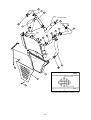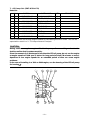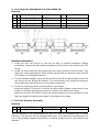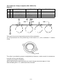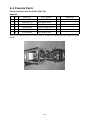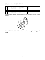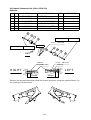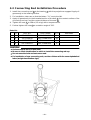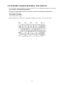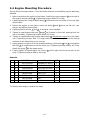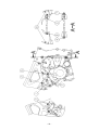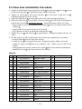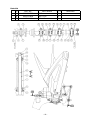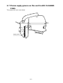
1
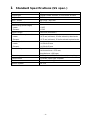
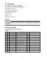
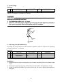
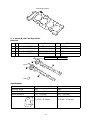
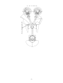
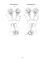
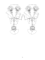
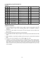
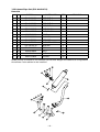
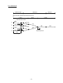
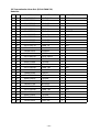
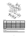
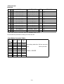
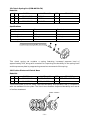
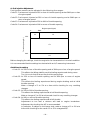
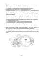
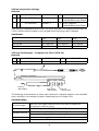
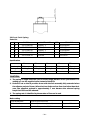
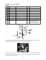
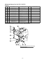
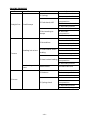
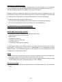
’04 YZF-R6
SS KIT MANUAL
The Performance Edge
for excellent riders
2003 YZF-R6 Kit Manual
Please note:
• Please understand that these parts are not covered by the warranty.
• The manufacturer does not take any responsibility for problems caused by these
parts.
• These kit parts are intended exclusively for racing purposes. You are strictly
requested not to use them for use on public roads.
• The specifications and usage methods of these kit parts along with the contents of
this manual are subject to change without notice for improvement.
• This manual has been written for persons having knowledge and experience in the
field of motorcycles. Please refer to the service manual for information on part
assembly and maintenance.
CONTENTS
1 Standard Specifications (SS spec.) ............................................................. 1
2 Kit Parts ......................................................................................................... 2
2-1 Basic Kit Set Contents ................................................................................... 2
2-2 Engine Parts .................................................................................................... 2
1.
2.
3.
4.
5.
6.
7.
8.
9.
10.
11.
12.
13.
14.
15.
16.
17.
18.
19.
20.
Maintenance Set (5SL-MAINT-70) ..................................................................... 2
Spark Plugs.......................................................................................................... 3
AIS Plug Set (5SL-A4890-70) .............................................................................. 3
Head Gaskets....................................................................................................... 4
Camshaft and Cam Sprockets............................................................................ 5
Sub Radiator Set (5SL-A240A-70).................................................................... 10
Oil Pump Set (5MT-A3100-70).......................................................................... 12
Air Funnel Set (Bell-Mouth Set) (5SL-A4460-70) ............................................ 13
Air Filter Element Assembly............................................................................. 13
Carburetor Clamp complete (5SL-1351A-70) .................................................. 14
Exhaust Pipe Set (5SL-A4600-70)..................................................................... 15
Transmission Gear Set (5SL-A7400-70) .......................................................... 18
Option Gear Set................................................................................................. 20
Sprockets ........................................................................................................... 21
Clutch Spring Set (5EB-A6330-70) ................................................................... 22
Friction Plate and Clutch Boss ......................................................................... 22
ACM Set (5SL-F1400-70)................................................................................... 23
Engine Control Unit (ECU)................................................................................ 24
Wire Harness Set (5SL-F2590-70) .................................................................... 32
Meter Stay Set (5SL-C8350-70) ........................................................................ 33
2-3 Chassis Parts................................................................................................. 34
21.
22.
23.
24.
25.
26.
27.
28.
29.
30.
31.
Oil Catcher Tank Set (5SL-C1707-70)............................................................... 34
Engine Protector Set (5SL-A5491-70) .............................................................. 35
Chassis Protector Set (5SL-C117G-70) ............................................................ 36
Rear Suspension Springs ................................................................................. 37
Front Fork Damper - Complete Set (5SL-C3170-70) ....................................... 37
Front Fork Spring .............................................................................................. 38
Throttle Set (5SL-C6300-70) ............................................................................. 39
Steering Damper Stay Set (5SL-C3495-70) ..................................................... 40
Front Disk Brake Assembly (5SL-2581T-70) .................................................... 41
Front Brake Pad Set (5SL-W0045-70)............................................................... 41
Footrest Set (5SL-C7400-70)............................................................................. 42
2-4 Other.............................................................................................................. 45
32. Valve Seat Cutter Set (5SL-M1112-70) ............................................................ 45
3 Assembly Precautions.................................................................................46
3-1 Checking the Valve Seats.............................................................................46
3-2 Connecting Rod Installation Procedure ......................................................48
3-3 Cylinder Head Installation Precautions.......................................................49
3-4 Engine Mounting Procedure ........................................................................50
3-5 Rear Arm Installation Procedure .................................................................52
3-6 Front Wheel Installation Procedure.............................................................54
3-7 Please apply grease on the wall in AIR CLEANER CASE...........................56
4 R6 Front Fork Manual (basic information) ................................................57
5 R6 Shock Absorber Manual (basic information).......................................62
2003 YZF-R6 Wiring Diagram .........................................................................67
Speed × Ratio table for YZF-R6 (2003)...........................................................68
1 Standard Specifications (SS spec.)
Item
Spec
Engine type
Liquid-cooled, 4-stroke, In-Line DOHC 4-valve
Displacement
599.7 cc
Bore × stroke
65.5 mm × 44.5 mm
Compression ratio
12.4 – 13.0 : 1
Valve timing (event angle)
Intake
Exhaust
= 105°
= 110°
Squish height
0.60 mm (minimum)
Minimum valve x piston clearance
Intake
Exhaust
= 0.75 mm (minimum), 10° after exhaust top dead center
= 1.75 mm (minimum), 11° before exhaust top dead center
Valve (tappet) clearance
Intake
Exhaust
= 0.20 ±0.03 mm
= 0.30 ±0.03 mm
Throttle body
38EIS MIKUNI
minimum bore = 37.5 mm,
throttle bore = 38.0 mm
Exhaust system
4-2-1 system, #1-2, #3-4 exhaust pipe coupling
Transmission
Constant mesh type, 6 speeds
Clutch
Wet, multi-disk type
Ignition system
DC-CDI
–1–
2 Kit Parts
2-1 Basic Kit Set Contents
Spark Plug Set (You can use STD SPARK PLUGS)
Head Gasket (t = 0.45 mm)
Camshafts and Cam Sprockets
Air Funnel Set (Bell Mouth Set)
Air Filter Element Assembly
AIS Plug Set
Clutch Spring Set
ACM Set
ECU and Wire Harness Set
Kit Manual
CAUTION:
Although those parts indicated with an asterisk (*) in the parts list are included in the kit
set, when individual parts are required, they are available through the general parts
sales channel.
2-2 Engine Parts
1. Maintenance Set (5SL-MAINT-70)
Parts List
No.
PART No.
PART NAME
Q'TY
*
1
5SL-11181-00
GASKET, CYLINDER HEAD
3
*
2
5SL-11603-00
PISTON RING SET
12
*
3
93210-17129
CIRCLIP
24
*
4
5SL-1165A-00
BOLT, CON-ROD
24
*
5
90179-07652
NUT
24
*
6
4TV-12119-00
SEAL, VALVE STEM
48
*
7
4FM-12213-00
GASKET, TENTIONER
3
*
8
5SL-13414-00
GASKET, STRAINER
3
*
9
5SL-15451-00
GASKET, COVER 1
3
*
10
5SL-15461-00
GASKET, COVER 2
3
*
11
5SL-15456-00
GASKET 1
3
*
12
5SL-15463-00
GASKET 2
3
*
13
93102-35423
SEAL, OIL
3
FOR DRIVE AXLE
*
14
90215-20231
WASHER
3
FOR CLUTCH BOSS
*
15
90151-06008
SCREW
9
FOR BEARING HOUSING
–2–
REMARKS
2. Spark Plugs
Parts List
No.
PART No.
1
5FL-94700-70
PART NAME
PLUG, SPARK
Q'TY
1
REMARKS
NGK R0045Q-10
Set No.: 5FL-R045Q-70 (R0045Q-10, 4 plugs)
CAUTION:
Since these spark plugs use a copper gasket, caution is required with respect to the
following points during installation.
1. The tightening torque is 1.0 – 1.2 kg·m.
2. When not controlling torque, tighten by turning only 30° after tightening by hand in
the case of new plugs. When reusing plugs, turn 15° to tighten.
Reused
(15˚)
New gasket
(30˚)
3. AIS Plug Set (5SL-A4890-70)
This plug set is used when AIS (Air Induction System), which is a device for purifying
exhaust emissions, is removed.
Parts List
No.
PART No.
PART NAME
Q'TY
1
5SL-1482L-70
PLATE
2
2
93608-16M16
PIN
4
3
90338-08026
PLUG
1
REMARKS
Installation
1. Remove the hose and accompanying air-cut valve assembly from the cylinder head
cover.
2. Remove the cap from the hose and take out the reed valve and plate from inside.
3. Install the plate (5SL-1482L-70) in place of the cap. Be sure to apply liquid gasket to
the plate.
–3–
4. Remove the cylinder head cover, then the four collars fitted in the head cover, and
install the PIN (93608-16M16).
5. After removing the hose that was connected from the air-cut valve assembly to the
air filter case, push in the plug (90338-08026) on the air filter side to clog up.
4. Head Gaskets
Parts List
No.
PART No.
PART NAME
Q'TY
REMARKS
1
5SL-11181-70
GASKET, HEAD CYL.
1
t=0.40 mm
2
5SL-11181-75
GASKET, HEAD CYL.
1
t=0.45 mm
3
5SL-11181-80
GASKET, HEAD CYL.
1
t=0.50 mm
4
5SL-11181-85
GASKET, HEAD CYL.
1
t=0.55 mm
• The standard gaskets have a thickness of 0.60 mm.
• These gaskets are used to adjust squish height. They are normally used at a squish
height of -75 (0.45 mm). In the case of machining the cylinder (upper case), always
make sure to measure the squish height and select the gaskets so that it is 0.60 mm
or more.
NOTE:
Squish height refers to the clearance between the flat surface of the piston and the
surface along the head cylinder.
–4–
Stamping location
5. Camshaft and Cam Sprockets
Parts List
No.
PART No.
PART NAME
1
5SL-12171-70
SHAFT, CAM 1
1
INT.296
2
5SL-12181-70
SHAFT, CAM 2
1
EXT.284
3
5SL-12176-70
SPROCKET, CAM 1
1
105°
4
5SL-12177-70
SPROCKET, CAM 2
1
110°
Tightening torque
Q'TY
REMARKS
24 Nm (2.4 m·kg)
STD
FWD.
Specifications
Intake
Exhaust
Working angle
296°
284°
Valve timing (sprocket)
105°
110°
Valve clearance
0.17 – 0.23 mm
0.27 – 0.33 mm
Cam lobe
a: 33.45 – 33.55 mm
b: 25.16 – 25.26 mm
a: 32.55 – 32.65 mm
b: 25.09 – 25.19 mm
–5–
Aligning of Valve Timing
• When assembling the camshaft, always make sure to align the valve timing. If this is
not done, not only will performance not be enhanced when the camshaft is
assembled, it will also cause damage to the engine.
• The valve timing (event angle) here refers to a crank angle formed from top dead
center when the valve is lifted highest.
• Use the cam sprocket included in the kit for aligning valve timing. The cam sprocket
included in the kit allows selection of five valve timings. In the case of aligning for the
purpose of attaining a minimum squish height of 0.60 mm, use of the center
mounting hole allows setting for intake valve timing of 105° and exhaust valve timing
of 110°.
• Valve timing adjustment range can be changed to either ±1° or ±2° relative to the
center mounting hole.
CAUTION:
1. In the case of using a new cam chain, make sure to wear in by assembling on the
cam sprockets as shown in the diagram below. Since the cam chain stretches by
approximately 1° after completion of wear-in, adjust by changing the cam sprocket
mounting positions after re-measuring the cam timing.
Cam sprocket mounting positions
(When cam chain is new)
–6–
–7–
EVENT ANGLE INT.
EVENT ANGLE EXT.
–8–
–9–
6. Sub Radiator Set (5SL-A240A-70)
Parts List
*
*
*
No.
PART No.
PART NAME
Q'TY
1
5SL-1240A-80
SUB RADIATOR ASSY
1
2
5SL-12467-70
COVER, RADIATOR
1
3
90465-13275
CLAMP
4
4
5SL-1244E-70
BRKT., 1
1
5
91317-06012
BOLT
1
6
5SL-12578-70
HOSE, 3
1
7
5SL-12584-70
JOINT, HOSE 3
1
8
5SL-12579-70
HOSE, 4
1
9
5SL-12552-70
HOSE, 8
1
10
5SL-12589-70
HOSE, 6
1
11
5SL-12588-70
HOSE, 5
1
12
5SL-12582-70
JOINT, HOSE 2
1
13
90450-38040
HOSE CLAMP ASSY.
12
REMARKS
Installation Precautions
1. This kit assumes that the muffler kit set is used. It cannot be mounted on the STD
muffler by itself, or may not be mounted either when a competitor’s muffler is
installed.
2. Use the STD main radiator. Also use the STD hose that goes into the radiator from
the oil cooler.
3. Remove the cleaning fan attached to the STD radiator.
4. Do not fasten the hose clamp too tight. The hose may become deformed and leak
water.
5. After installation, check that the radiator and hose are not in contact with the exhaust
pipe.
6. Pass the clutch wire alongside on the outside of 12 (Joint, hose)
7. Trapped air in the water passage reduces the cooling efficiency. When refilling water,
incline the motorcycle right and left to allow no water to remain in the water passage.
After refilling, idle run the engine for a while with the radiator cap removed. Then add
water to fill up the vacancy produced by escaping water and tighten the cap securely
on the radiator.
– 10 –
STD
WATER PUMP
THERMOSTAT
SUB
RADIATOR
STD
MAIN
SUB
Upper assembly diagram (viewed in front)
– 11 –
7. Oil Pump Set (5MT-A3100-70)
Parts List
No.
PART No.
PART NAME
Q'TY
1
5MT-13336-00
HOUSING, ROTOR
1
2
5EB-13316-70
COVER, PUMP
1
3
5EB-13330-70
PUMP SHAFT ASS'Y
1
*
4
1WG-13310-00
ROTOR ASS'Y
1
*
5
93603-17070
PIN, DOWEL
1
*
6
93603-09106
PIN, DOWEL
2
*
7
91317-06025
BOLT
3
*
8
90201-113K2
WASHER
1
9
5MT-13319-70
SPACER
1
REMARKS
This kit reduces loss at high engine speeds by decreasing the rotor width. This can be
expected to result in a 1 – 2% improvement in output.
CAUTION:
During maintenance, place engine oil inside the pump after assembling and rotate the
shaft to confirm that it rotates smoothly.
Since the amount of oil discharged is less than the STD oil pump, do not run the engine
at engine speeds of 3000 rpm or below for long period of time (30 minutes or more).
Operation at low engine speeds for an extended period of time can cause engine
problems.
In the case of installing in a 1999 or 2000 engine, use the housing of the STD oil pump
for housing 1 .
– 12 –
8. Air Funnel Set (Bell-Mouth Set) (5SL-A4460-70)
Parts List
No.
PART No.
PART NAME
1
5SL-14463-70
JOINT. 2
2
2
5SL-14469-75
FUNNEL, 1
2
3
5SL-14454-70
JOINT
2
4
5SL-14479-70
FUNNEL
2
#2
#1
Q'TY
#3
REMARKS
L=24 mm
L=9 mm
#4
Installation Precautions:
1. Install the joint and funnel so that the air filter is located in-between. Before
installation, remove the plate attached under the STD air filter case and then the STD
funnel.
2. Install the funnel and joint after applying a thin coat of grease to their threads. They
may have a little gap between them and the case but do not become loose with the
STD rubber joint and plate fastened.
3. For the standard settings, use the 9 mm funnel for the #1 and #4 cylinders and the 24
mm funnel for the #2 and #3 cylinders. This combination may change according to
the exhaust pipe specifications or to the rider’s preference.
4. Tendency subject to the funnel combination is as follows:
When the longer STD funnel is used for the #2 and #3 cylinders, power tends to be
weaker in the high rev range but easier to handle in the medium-rev range.
When the shorter STD funnel is used, the engine tends to be more responsive in the
high-rev range but produce less torque in the medium-rev range.
9. Air Filter Element Assembly
Parts List
No.
PART No.
1
5SL-14450-70
PART NAME
ELEMENT ASS'Y
Q'TY
REMARKS
1
This air element is an improvement on the STD with an increased 20% of intake
efficiency. The raising in the air passage sheds water, so the element is also effective in a
run in rainy weather. Regular maintenance is simple; simply blow air on the back of the
element.
– 13 –
10.Carburetor Clamp complete (5SL-1351A-70)
Parts List
No.
PART No.
PART NAME
Q'TY
*
1
90450-63001
BAND
4
*
2
95307-04600
NUT
4
3
5SL-13573-70
BOLT, 1
3
4
5SL-1358A-70
ROD COMP.
1
REMARKS
This part is the one to improve the service of the carburetor.
Cut off prominence for the positioning of the band is in “joint, carburetor 1” before
using.
Cut off
The collar is provided to prevent overtightening. However, under normal circumstances,
it would not become that tight.
Tightening by hand is sufficient.
When tightening the opening portion by hand, the gap measures approx. 9 mm.
After threading M4 × 0.7, a new band must be used.
– 14 –
11.Exhaust Pipe Set (5SL-A4600-70)
Parts List
No.
PART No.
PART NAME
Q'TY
1
5SL-14611-70
PIPE, EXT. 1
1
2
5SL-14621-70
PIPE, EXT. 2
1
3
5SL-14631-70
PIPE, EXT. 3
1
4
5SL-14641-70
PIPE, EXT. 4
1
5
5EB-14612-70
NUT, RING 1
4
6
5EB-14622-70
NUT, RING 2
4
*
7
92017-08016
BOLT
8
*
8
3YF-14613-01
GASKET
4
9
5SL-14785-70
DIFFUSER
1
10
5SL-14750-70
SILENCER ASS'Y
1
11
5SL-1471K-70
BRACKET
1
12
5SL-21445-70
STAY
1
*
13
92014-08020
BOLT
3
*
14
95607-08200
NUT
3
*
15
90507-20030
SPRING
10
REMARKS
Made entirely of titanium, this exhaust set has less weight and features a configuration
that allows a sub-radiator to be installed.
– 15 –
CAUTION:
Reroute the clutch wire as shown below so as to prevent it from contacting the exhaust
pipe.
Piping for auto starter
Pass the clutch wire on the
outside of the radiator hose.
Take care to avoid contact with the cowling.
– 16 –
EXT. DIMENSION
Exhaust pipe
Diffusser
Silencer
Pipe outside diameter (Plate thickness t1.2)
ø 38.1
ø 42.7
ø 50.8
Exhaust port outlet
#
1
#
2
#
3
#
4
420
#
#
79( 1~ 4)
ø12
277
434
400
(Inside diameter)
437
286
ø12
422
60
Tapered portion
250
Connecting point
– 17 –
550
12.Transmission Gear Set (5SL-A7400-70)
Parts List
No.
PART No.
1
5SL-17411-80
AXLE, MAIN
1
2
90387-253M6
COLLAR
1
3
5SL-17151-70
GEAR, 5P
1
*
4
90209-21332
WASHER
2
*
5
93440-25084
CIRCLIP
2
6
5SL-17131-80
GEAR, 3P
1
7
90387-2513E
COLLAR
1
8
5SL-17161-70
GEAR, 6P
1
*
9
90209-22352
WASHER
1
*
10
90209-21351
WASHER
1
11
5SL-17121-70
GEAR, 2P
1
*
12
5EB-15163-01
HOUSING
1
*
13
93306-30525
BEARING
1
*
14
90151-06008
SCREW
3
*
15
5SL-17421-00
AXLE, DRIVE
1
*
16
93306-30546
BEARING
1
*
17
90387-2504A
COLLAR
1
*
18
90387-2813C
COLLAR
1
19
5SL-17221-80
GEAR, 2W
1
*
20
90209-25342
WASHER
3
*
21
93440-28062
CIRCLIP
3
22
5SL-17261-70
GEAR, 6W
1
23
90387-2813D
COLLAR
2
24
5SL-17241-70
GEAR, 4W
1
*
25
90209-25349
WASHER
1
*
26
90209-25350
WASHER
1
27
5SL-17231-80
GEAR, 3W
1
27T
28
5SL-17251-70
GEAR, 5W
1
30T
29
90387-2202V
COLLAR
1
30
5SL-17211-80
GEAR, 1W
1
31
93102-35423
SEAL, OIL
1
*
*
*
*
*
PART NAME
– 18 –
Q'TY
REMARKS
16T
26T
19T/25T
22T
21T
36T
24T
31T
34T
Gear Ratio
Speed
5SL-A7400-70
No. of teeth
(gear ratio)
A (OPTION)
No. of teeth
(gear ratio)
C (OPTION)
No. of teeth
(gear ratio)
STD (Reference)
No. of teeth
(gear ratio)
1st
34/16 (2.125)
31/15 (2.066)
32/14 (2.285)
37/13 (2.846)
2nd
36/21 (1.714)
35/21 (1.666)
—
37/19 (1.947)
3rd
27/19 (1.421)
29/21 (1.380)
—
28/18 (1.555)
4th
31/25 (1.240)
(←)
—
32/24 (1.333)
5th
30/26 (1.153)
(←)
—
25/21 (1.190)
6th
24/22 (1.090)
(←)
—
26/24 (1.083)
L/T
1.894
1.947
(2.095)
2.628
CAUTION:
The gears of the kit transmission and those of the standard transmission are completely
incompatible.
Only combine the gears provided in the kit transmission set.
– 19 –
13.Option Gear Set
1stGEAR SET A (5SL-A7411-70)
Parts List
No.
PART No.
1
5SL-17411-70
PART NAME
AXLE, MAIN
1ST
Q'TY
1
15T
1
31T
2
5SL-17211-70
GEAR,
3
5EB-15163-01
HOUSING
1
4
93306-30525
BRG.
1
WHEEL
REMARKS
1STGEAR SET C (5SL-A7411-90)
Parts List
No.
PART No.
PART NAME
Q'TY
REMARKS
1
5SL-17411-90
AXLE, MAIN
1
14T
2
5SL-17211-90
GEAR, 1ST WHEEL
1
32T
3
5EB-15163-01
HOUSING
1
4
93306-30525
BRG.
1
2ndGEAR SET A (5SL-A7421-70)
Parts List
No.
PART No.
PART NAME
2ND
Q'TY
REMARKS
1
5SL-17121-70
GEAR,
PINION
1
21T
2
5SL-17221-70
GEAR, 2ND WHEEL
1
35T
3rdGEAR SET A (5SL-A7431-70)
Parts List
No.
PART No.
1
5SL-17131-70
GEAR, 3RD PINION
1
21T
5SL-17231-70
3RD
1
29T
2
PART NAME
GEAR,
WHEEL
Q'TY
REMARKS
CAUTION:
1. These gear sets are capable of a combination with the transmission gear sets
contained in the basic kit.
2. They are not interchangeable with the STD transmission gears. If installed, they will
cause trouble.
– 20 –
14.Sprockets
Parts List
No.
PART No.
PART NAME
Q'TY
REMARKS
1
4FN-17460-74
SPROCKET, DRIVE
1
14T
2
4FN-17460-75
SPROCKET, DRIVE
1
15T
3
4FN-17460-76
SPROCKET, DRIVE
1
16T
4
4FN-17463-71
NUT
1
5
5SL-25445-70
SPROCKET, REAR
1
45T
6
5SL-25446-70
SPROCKET, REAR
1
46T
7
5SL-25447-70
SPROCKET, REAR
1
47T
8
5SL-25448-70
SPROCKET, REAR
1
48T
9
5SL-25449-70
SPROCKET, REAR
1
49T
10
5SL-25450-70
SPROCKET, REAR
1
50T
11
5SL-25451-70
SPROCKET, REAR
1
51T
12
5SL-25452-70
SPROCKET, REAR
1
52T
These parts are for 520 chain size (the standard size is 532).
Use the drive sprocket mounting nut from the kit.
<Gear Ration Conversion Table>
Front
Rear
45T
14T
15T
16T
3.214
3.000
2.812
46T
3.285
3.066
2.875
47T
3.357
3.133
2.937
48T
3.428
3.200
3.000
49T
3.500
3.266
3.062
50T
3.571
3.333
3.125
51T
3.642
3.400
3.187
52T
3.714
3.466
3.250
Secondary reduction =Driven sprocket
ratio
drive sprocket
CHAIN = 520SIZE.
– 21 –
15.Clutch Spring Set (5EB-A6330-70)
Parts List
No.
PART No.
PART NAME
Q'TY
1
3FV-2304E-70
SPRING
6
2
5EB-90159-70
SCREW
6
3
5EB-16559-70
WASHER
6
REMARKS
Specifications
Kit
Standard
Identification color
Red
White
Free length
50.2 mm
50.0 mm
Mounting load
24.1 kgf
19.8 kgf
Mounting height
29.6 mm
29.6 mm
Tightening torque 80 Nm (8.0 m·kg)
This clutch spring set contains a spring featuring increased pressure load of
approximately 20%, along with a washer for improving the durability of the spring itself
and the pressure plate by suppressing excessive movement of the spring.
16.Friction Plate and Clutch Boss
Parts List
No.
PART No.
PART NAME
Q'TY
1
5EB-16321-72
PLATE, FRICTION
8
2
5SL-16371-70
BOSS, CLUTCH
1
REMARKS
SET=5EB-A6321-72
The friction plate of this kit offers improved durability and operation feel in comparison
with the standard friction plate. The clutch boss features improved durability as a result
of surface treatment.
PAINT "VIOLET"
– 22 –
17.ACM Set (5SL-F1400-70)
Parts List
No.
PART No.
PART NAME
Q'TY
1
5SL-81410-70
STATOR ASS'Y
1
2
5SL-81450-70
ROTOR
1
3
5SL-15590-00
STARTER CLUTCH
1
4
90149-08003
BOLT
3
5
5SL-15411-70
COVER
1
6
91317-06025
BOLT
4
7
92907-06600
WASHER
4
8
5SL-15451-00
GASKET
1
REMARKS
ASS’Y=5SL-81400-70
Installation Precautions
1. Before installing the rotor to the crank, degrease both of their tapers.
2. Before installation, apply engine oil to the thread and flange of the installation bolts.
3. When installing the stator coil to the cover, apply LOCTITE® to the bolts.
Tightening torque 32 Nm (3.2 m·kg)
Apply LOCTITE®.
Tightening torque 12 Nm (1.2 m·kg)
STD
Tightening torque 60 Nm (6.0 m·kg)
– 23 –
18.Engine Control Unit (ECU)
Parts List
No.
PART No.
1
5SL-8591A-70
PART NAME
ENGINE CONTROL UNIT
Q'TY REMARKS
1
• Using the wire harness supplied in the kit, you can switch to control data of SS
(Super Sports) specification or to control data of ST (Stock Sports) specification.
• SS specification is preset in the state in which the kit camshaft and the 2003 spec kit
muffler and kit air filter are used.
ST specification is preset in the state in which only the muffler is changed into kit
parts.
A change to ST specification can be made by removing the black 2-pin coupler
located under the kit harness seat.
• Fuel injection is automatically adjusted responding to a change in atmospheric
temperature and pressure. However, a change in the engine specification (as in the
camshaft, valve timing, muffler, compression ratio, etc.) may result in malfunction.
• With the STD meter, this ECU can adjust the fuel injection and offset the ignition
timing.
CAUTION:
• This ECU cannot be used for the motorcycles of European and Australian
specifications (with the wire harness number 5SL-82590-00) unless the kit wire
harness (5SL-82590-70) is used in combination.
• The STD harness can be used in the motorcycles of USA and Canadian
specifications, though with the ST specification control data.
– 24 –
A: Fuel injection Adjustment
Fuel injection amount can be adjusted in the following four ranges:
Code C1: Fuel amount injected at 25% or less of throttle opening and at 3000 rpm or less
of engine speed
Code C2: Fuel amount injected at 25% or less of throttle opening and at 3000 rpm or
more of engine speed
Code C3: Fuel amount injected at 25% to 90% of throttle opening
Code C4: Fuel amount injected at 90% or more of throttle opening
Engine speed (rpm)
0
3000
C1
C2
Throttle opening (%)
25%
C3
90%
C4
Before changing the settings, check the engine for its characteristics in normal condition.
It is recommended that the settings be checked with an A/F measuring instrument.
Guidelines for setting
• Code C1: At 25% or less of throttle opening and at 3000 rpm or less of engine speed:
This affects the idling stability and the feeling experienced during races.
Too rich an air-fuel mixture may foul the spark plugs.
• Code C2: At 25% or less of throttle opening and at 3000 rpm or more of engine
speed:
This affects the feeling experienced during engine braking and at initial
throttle opening.
Make a change of 2 to 5% at a time while checking for any resulting
changes.
• Code C3: At 25% to 90% of throttle opening:
This affects the feeling experienced at half throttle opening.
Make a change of 2 to 5% at a time and check for any resulting changes.
• Code C4: At 90% or more of throttle opening:
This affects the feeling experienced at full throttle.
Adjustment to too lean a mixture will lead to engine breakdown.
Adjustment by checking the A/F is recommended.
In particular, to adjust on the leaner side, make a change of 1 to 2% at a
time while checking for the result. 12 to 13 is a targeted A/F.
– 25 –
Adjustment
• Transfer to adjustment mode.
While holding down both the “RESET” and “SELECT” buttons on the meter, turn on
the main switch (the engine stop switch will not function).
“Co” appears in the left of the area for displaying the time and distance.
1. Press both the “RESET” and “SELECT” buttons at the same time.
The display changes from “Co” to “C1”. Each time the “SELECT” button is pressed in
this state, the display changes to “C2”, “C3”, “C4”, and again “C1” and so forth. Each
time the “RESET” button is pressed, the display goes back to the previous setting.
2. When the code to be changed appears, press both the “RESET” and “SELECT”
buttons at the same time.
The adjustment value appears to the right of the code display. To change the
adjustment value, press either the “RESET” or the “SELECT” button. Each time either
button is pressed, the display changes by “1”.
This value indicates the change in % in relation to the reference value. For example:
“0” indicates the reference value.
“–10” indicates a change of “–10%” in relation to the reference value.
“20” indicates a change of “+20%” in relation to the reference value.
3. The adjustment value has an allowance of ±25%.
Pressing the button beyond this allowance will not change either the display or
adjustment value.
4. When another code is changed, press both the “RESET” and “SELECT” buttons at
the same time. The display returns to the state as described in the above 2.
• Checking/finishing
Turn off the main switch, and the adjustment mode will be finished.
The adjusted values are stored in memory. You do not have to turn off the main
switch.
– 26 –
B: Offset at ignition
This function corrects the general differences in the ignition timing requirements caused
by different fuels etc.
Adjustment
• Transfer to adjustment mode
While holding down the “RESET” and “SELECT” buttons on the meter, turn on the
main switch (the engine stop switch will not function).
“Co” appears in the left of the display area for the time and distance.
1. Press the “SELECT” button.
The display changes to “dIAG “.
2. Press both the “SELECT” and “RESET” buttons at the same time.
“d01: XX” appears in the display area.
3. Press the “RESET” button 4 times.
Check that “d60: 00” is displayed.
4. In this state, operate the engine stop switch “OFF” → “ON”.
“d60: 02” is displayed. This indicates that the ignition timing is 2° too early in
relation to the standard state.
Repetition of “OFF” → “ON” on the engine stop switch repeats the following
sequential display, starting from “d60 00”.
“d60: 02” (2° advance)
“d60: 04” (4° advance)
“d60: 06” (6° advance)
“d60: 86” (6° retard)
“d60: 84” (4° retard)
“d60: 82” (2° retard)
“d60: 00” (standard ignition timing)
5. When selection is finished, turn off the main switch to complete the procedure.
CAUTION:
Ignition timing adjustment function covers a range of over 3000 rpm.
Over-adjustment on the advance side may do damage to the engine, so take sufficient
care to work with the adjustment. If selection on the advance side appears to bring
about no change or if there is any doubt as to which to select, make settings on the
retard side.
• Bring the fuel adjustment and ignition timing back to the standard state.
Perform the following method in order to bring the fuel adjustment and ignition
timing back to the standard state all at once.
1. Select Code 61 = “d60: 00”.
2. Operate the engine stop switch “OFF” → “ON”. “d60: 55” appears, all coming back
to the standard state.
– 27 –
C: Location for water temperature display and unit conversion
The ECU in the kit has an additional function of displaying the water temperature in the
speed display area.
CAUTION:
This function assumes that speed is displayed in the “km/h” unit on the meter.
If the meter displays speed in miles, perform the following steps and change the speed
display.
1. Turn on the main switch.
If the clock is displayed in the distance/clock area, press the “SELECT” button for
more than a second to change it over to the distance display.
2. Holding down both the “SELECT” and “RESET” buttons for more than 2 seconds
changes the speed display from “mph” to “km/h”.
3. When the main switch is turned off, the settings will be stored in memory, though a
disconnected battery nulls it and brings the display back to the original “mph”
display.
Switching over the water temperature display
1. Turn on the main switch with the “RESET” and “SELECT” buttons held down.
“Co” appears in the left of the display area for the distance and time.
2. Press the “SELECT” button. The display changes to “dIAG “.
3. Press both the “RESET” and “SELECT” buttons at the same time.
“d01: xx” appears in the display area. (A certain number is displayed in “xx”.)
4. Pressing the “RESET” button 2 times displays “d62: xx”.
The “xx” in “d62: xx” indicates which thermometric scale to display, Celsius or
Fahrenheit.
“00” = No display
“01” = Celsius (°C)
“02” = Fahrenheit (°F)
To change the display, operate the engine switch “OFF” → “ON”. The thermometric
indication changes in order of “00”, “01”, “02”, and back to “00” and so on.
5. When the desired scale appears, turn off the main switch.
CAUTION:
Even when water temperature is displayed in the speed indication area, the figures in
the distance display area will be changed though they do not represent the actual
distance traveled.
D: Self-diagnosis function
The ECU in the kit is designed to display the code number on the STD meter
corresponding to the failure occurring to the sensors and switches.
For these code numbers, refer to Table 1.
– 28 –
E: Diagnosis (function for checking the condition)
The ECU in the kit makes it possible to check whether the sensors and switches are
working properly through the following operation by using the STD meter.
Operation
1. Turn on the main switch while holding down both the “SELECT” and “RESET”
buttons at the same time. “Co” is displayed in the meter display area.
2. Press the “SELECT” button. The display changes to “dIAG”.
3. Press both the “SELECT” and “RESET” buttons at the same time. “d01: xx” appears
in the display area.
The “xx” in “d01: xx” represents the code number indicating the diagnosis function.
For the details of the code numbers, refer to Table 2.
4. After checking, turn off the main switch to complete the procedure.
Table 1 <Finding failures through self-diagnosis>
Abnormal
code
Item
Operation of ECU
Engine
run
Cam sensor
• Cam sensor broken/shorted
• Cam sensor broken down
(Found during electric motor cranking)
Impossible
12
Crank sensor
• Crank sensor broken/shorted
• Crank sensor broken down
(Found during electric motor cranking)
Impossible
13
Intake pressure
sensor
(broken/shorted)
• Intake pressure sensor broken/shorted
• Intake pressure sensor broken down,
abnormal value
Possible
14
Intake pressure
sensor
(Piping system
failure)
• Intake pressure sensor piping coming off.
• Intake pressure sensor broken down,
abnormal value
(Found during engine run)
Possible
15
TPS
(Broken/shorted)
• Throttle sensor broken/shorted
• Throttle sensor broken down/abnormal
value
Possible
21
Water temperature
sensor
(Broken/shorted)
• Water temperature sensor broken/shorted
• Water temperature sensor broken down/
abnormal value
Possible
22
Intake temperature
sensor
(Broken/shorted)
• Intake temperature sensor broken/shorted
• Intake temperature sensor broken down/
abnormal value
Possible
23
Ambient pressure
sensor
(Broken/shorted)
• Ambient pressure sensor broken/shorted
• Ambient pressure sensor broken down/
abnormal value
Possible
11
– 29 –
Abnormal
code
Item
30
Turnover sensor
(overturned
checked)
33
Abnormal ignition
#1
34
Abnormal ignition
#2
35
Abnormal ignition
#3
36
Abnormal ignition
#4
Operation of ECU
• Vehicle overturned
• Engine can be restarted if code goes off
when vehicle stands erect.
(Turnover sensor broken down/abnormal
value)
Engine
run
Impossible
• Ignition coil coming off/broken
Possible
41
Turnover sensor
(Broken/shorted)
• Turnover sensor broken/shorted
• Turnover sensor broken down/abnormal
value
Possible
43
Battery voltage
(Voltage for fuel
system)
• Main relay broken down
• ECU detection wire broken
Possible
50
ECU interior
broken down
(Abnormal ROM
data)
• Abnormal data in ECU
Impossible
*NOTE: Even if the engine is capable of running during failure, it is a mere passing
operation and may not produce its intended function and performance.
– 30 –
Table 2 <Diagnosis function>
CODE
Item
Operation of ECU
01
Throttle sensor
• Displays throttle sensor input value in angles.
• Approx. [17] deg at full closed throttle
• Approx [95] deg at full open throttle
02
Ambient pressure sensor
• Displays ambient pressure in mmHg.
• Approx. [760] mm Hg at standard altitude
03
Intake pressure sensor
• Displays intake negative pressure in kPa.
• Approx. [80] mmHg at electric motor cranking
05
Intake temperature sensor
• Displays sensor detected temperature in °C.
06
Water temperature sensor
• Displays sensor detected temperature in °C.
07
Vehicle speed sensor
• Displays accumulated number of sensor
detected pulses.
08
Turnover sensor
• Displays sensor output voltage.
Erect:
[0.4 to 1.4] V
Overturned: [3.7 to 4.4] V
Broken:
[5.0] V
09
Monitor voltage
• Displays battery voltage measured by ECU.
Approx. [12] V when checking.
20
Engine kill-switch
• Displays switch condition.
• “ON” is displayed while switch is operated.
30
Ignition coil #1
31
Ignition coil #2
32
Ignition coil #3
33
Ignition coil #4
36
Injector #1
37
Injector #2
38
Injector #3
39
Injector #4
50
Main relay
• Drives main relay 5 times every second.
60
Selection of ignition
timing
• Set offset value for ignition timing.
61
Initialization of value
changed
• Reset injection adjustment value and ignition
timing offset amount to initial value.
62
Selection of water
temperature display
• Selects function for water temperature
displayed on meter
00: Nothing 01: Celsius 02: Fahrenheit
• Drives ignition coil 5 times every second.
• Drives injector 5 times every second.
– 31 –
19.Wire Harness Set (5SL-F2590-70)
Parts List
No.
PART No.
PART NAME
Q'TY
1
5SL-82590-70
HARNESS ASS'Y
1
2
5FL-83976-70
SWITCH, MAIN
1
REMARKS
• Do not remove the AC generator but leave it to function. Using the battery alone will
result in the inability to run in a short time.
• This harness enables the meter to light up when the main switch is turned on.
• The circuit to the oil level gauge and the fuel sender need not be connected, though
the oil warning light and fuel warning light come on. But there will be no problem
with a run.
* Use STD parts for the following.
Engine stop switch
Relay assembly
Emergency stop switch
Battery positive lead
Battery negative lead
CAUTION:
When installing the emergency stop switch, take care to insert the coupler straight in so
that the terminal is not bent.
Other functions
• Combination with the ECU in this harness kit enables the engine stop switch to be
used.
Attach the switch between the black leads or between the black/yellow (BY) and the
black (B) lead, which are shorted on the white 3-pin coupler under the tank.
When the switch is on, it cuts ignition, but note that it does not function when
transmission is running.
• When the black 2-pin coupler located under the seat is removed, the ECU control data
changes to the ST specification. Note, however, that the engine stop switch functions
only with the STD transmission.
– 32 –
20.Meter Stay Set (5SL-C8350-70)
Parts List
No.
PART No.
PART NAME
1
5SL-28356-70
STAY, 1
1
2
5SL-83519-70
BRKT., METER
1
*
3
90149-06298
SCREW
2
*
4
95704-06500
NUT, FLANGE
2
*
5
4XV-83513-00
DAMPER
3
6
5SL-28321-70
STAY, 1
1
LH
7
5SL-28322-70
STAY, 2
1
RH
*
8
95807-06025
BOLT, FLANGE
2
*
9
95307-06600
NUTR, HEX.
2
*
10
92907-06200
WASHER, PLAIN
2
*
11
4A0-28364-00
NUT
2
*
12
4DP-28334-00
CLIP, COWLING
2
*
13
90150-06021
SCREW, ROUND HEAD
2
The rearview mirror and headlight cannot be installed.
– 33 –
Q'TY
REMARKS
2-3 Chassis Parts
21.Oil Catcher Tank Set (5SL-C1707-70)
Parts List
No.
PART No.
PART NAME
Q'TY
1
5SL-21707-70
OIL TANK COMP
1
2
5EB-15373-70
PIPE, BREATHER
2
*
3
90464-15152
CLAMP
2
*
4
90450-25037
HOSE CLAMP ASS'Y
6
5
5SL-11166-70
PIPE, BREATHER
1
6
371-11166-01
PIPE, BREATHER
1
REMARKS
L=370 mm
This actual capacity of this oil tank is 1000 cc. Install behind the rear frame above the rear
fender.
– 34 –
22.Engine Protector Set (5SL-A5491-70)
Parts List
No.
PART No.
PART NAME
Q'TY
1
5SL-15491-70
PROTECTOR
1
*
2
91314-06030
BOLT
2
*
3
91314-06025
BOLT
1
*
4
90387-065X6
COLLAR
3
5
91314-06035
BOLT
2
REMARKS
This part reduces damage when the motorcycle tips over along with the chassis
protector.
For the YZF-R6 in the 1999 to 2002 model years, use the collars 4 . Use 1 bolt 2 and 2
bolts 5 .
– 35 –
23.Chassis Protector Set (5SL-C117G-70)
Parts List
No.
PART No.
PART NAME
Q'TY
REMARKS
1
5EB-2117G-70
PROTECTOR
2
2
5SL-21472-70
COLLAR, PROTECTOR
1
LH
3
5SL-21477-70
COLLAR, PROTECTOR 2
1
RH
4
91317-10090
BOLT, HEX. SOCKET
1
LH
5
91317-10060
BOLT, HEX. SOCKET
1
RH
6
90201-10140
WASHER, PLATE
2
Tightening torque
40 Nm (4.0 m·kg)
SUPT., ENGINE
ENGINE
Tightening torque
40 Nm (4.0 m·kg)
FWD
FRAME
ENGINE
RIGHT
SUPT., ENGINE
FRAME
LEFT
23mm
28mm
Remove the arrowed bolts and install the chassis protector using the supplied bolts. Cut
the cowling to fit the vehicle.
– 36 –
24.Rear Suspension Springs
Parts List
No.
PART No.
1
5SL-22212-70
2
5SL-22212-80
PART NAME
Q'TY
REMARKS
SPRING, 1
1
K=10.7 kgf/mm
(Identification color: Black)
SPRING, 1
1
K=11.2 kgf/mm
(Identification color: Blue)
This spring is intended for use in the STD shock absorber. It is slightly shorter than the
STD so that the vehicle height is not changed when the spring rate is changed.
Specification
–70
–80
STD
Free length
168 mm
167 mm
168.5 mm
Spring rate
10.7 kgf/mm
11.2 kgf/mm
10.0 kgf/mm
ID (paint on number of end coils)
Black
Blue
Nil
25.Front Fork Damper - Complete Set (5SL-C3170-70)
Parts List
No.
PART No.
1
5SL-23170-70
Gasket
2K8 23158-L0
PART NAME
DAMPER COMP.
Slide metal
5EB-23125-00
Q'TY
REMARKS
1
Oil seal
4PU-23145-01
The damping characteristics of these parts have been changed relative to the standard
parts, resulting in an average increase in damping force of roughly 25%.
Standard Setting
Oil level height
106 mm, from upper surface of the inner tube at maximum
compression without spring
Recommended oil
Yamaha Suspension Oil 01 (SAME AS SAE 0W)
Standard settings
Rebound damping: 9 clicks out from full turn in
Compression damping: 7 clicks out from full turn in
Preload
7 mm (where preload adjuster projects 20 mm)
Stroke
120 mm (same as STD)
– 37 –
26.Front Fork Spring
Parts List
No.
PART No.
PART NAME
Q'TY
REMARKS
1
5SL-23141-80
SPRING, 1
0.90 kgf/mm
1
5SL-23141-85
SPRING, 1
0.95 kgf/mm
1
5SL-23141-90
SPRING, 1
1.00 kgf/mm
1
5SL-23141-95
SPRING, 1
1.05 kgf/mm
2
5SL-23118-70
SPACER
L=53 mm
Specification
–80
–85
–90
–95
STD
Free length
290 mm
290 mm
290 mm
290 mm
250 mm
Spring rate
0.90 kgf/mm
0.95 kgf/mm
1.00 kgf/mm
1.05 kgf/mm
0.85 kgf/mm
No. of ID marks
3
4
5
6
Nil
CAUTION:
1. The spring is longer than the STD in overall length because of its specification. For
setting up, use the supplied collar instead of the STD.
2. Preload is set so that it provides 0 mm with the fork assembly fully extended when
the adjuster projects 20 mm. When the front forks are free from load other than their
own, the apparent preload is approximately 7 mm because the rebound spring
keeps the fork from full rebound.
3. The spring rate is identified by the number of lines on its end.
Basic setting
Preload adjuster
20 mm (up to top end)
Oil level
106 mm (when compressed)
Suspension oil
Yamaha Suspension Oil 01
– 38 –
Approx. 490cc
27.Throttle Set (5SL-C6300-70)
Parts List
No.
PART No.
1
5EB-26281-81
CAP, GRIP UPPER
1
2
5EB-26282-81
CAP, GRIP UNDER
1
3
5FL-26391-80
CLIP, THROTTLE WIRE
1
4
5SL-26302-70
THROTTLE WIRE ASS’Y
1
*
5
91317-05020
BOLT
2
*
6
91317-05014
BOLT
1
*
7
5SL-26243-71
TUBE GUIDE
1
8
4YR-26242-00
GRIP2
1
9
90201-261L1
WASHER
1
10
4UN-83975-01
SW., HANDLE 2
1
11
5SL-8258A-70
EXTENTION, HARNESS 2
1
*
PART NAME
Q'TY
REMARKS
Install this part between
SW., HANDLE2 and wire
harness on the motorcycle.
This part allows the throttle grip to be removed without removing the carburetor wire to
facilitate easier maintenance. The operating angle is 50 degrees.
The engine stop switch is changed to the one provided. There is a projection on the
bottom of the switch that is used as a reference for positioning. Install the stop switch
after removing this projection.
– 39 –
28.Steering Damper Stay Set (5SL-C3495-70)
Parts List
No.
PART No.
1
5EB-23495-70
STAY, DAMPER
1
*
2
91701-08038
PIN
1
*
3
90201-08455
WASHER
1
*
4
90468-16099
CLIP
1
*
5
91317-06025
BOLT, HEX. SOCKET
1
6
5EB-2349T-72
BRKT.
1
*
7
90101-08766
BOLT
2
*
8
92907-08200
WASHER
2
*
9
95707-08500
NUT, FLANGE
2
*
10
91317-08030
BOLT, HEX. SOCKET
1
11
5EB-21312-71
STOPPER, STRG.
1
12
92017-06016
BOLT, BUTTON HEAD
1
*
PART NAME
Q'TY
REMARKS
Use the steering damper OHLINS SD1210 with a 68 mm stroke.
Drill an M6 screw-thread hole in the frame.
(18 to 20 mm deep)
– 40 –
29.Front Disk Brake Assembly (5SL-2581T-70)
Parts List
No.
PART No.
PART NAME
Q'TY
1
5SL-2582T-70
DISK
1
2
5SL-25832-70
BRACKET
1
3
5EB-2581M-70
PIN
7
4
5EB-2581N-70
WASHER
7
5
5EB-93430-70
CIRCLIP
7
REMARKS
The disk thickness and heat treatment of these parts has been changed for racing use,
resulting in improved durability and operation. Yamaha genuine part 93430-09038 can
also be used for the circlip.
30.Front Brake Pad Set (5SL-W0045-70)
Parts List
No.
PART No.
PART NAME
Q'TY
1
5SL-25811-70
PAD. COMP.
4
2
5SL-25827-70
SHIM, 1
4
REMARKS
• These parts feature improved stopping power for racing use. They can also be used
on the YZF-R1.
Since these pads grip the disk more strongly than the standard pads, if braking feels
poorly when the brake is applied or if the pads appear to be slipping, check the
braking surface of the disk and replace the disk as necessary.
• The supports are installed to make it difficult for heat from the brake pads to be
transferred to the caliper. Always make sure to install these supports on the pads.
– 41 –
31.Footrest Set (5SL-C7400-70)
Parts List
No.
PART No.
1
5SL-27412-70
BRKT., 1
1
2
5SL-27452-70
BRKT., FOOTREST 1
1
*
3
90151-08022
SCREW
4
*
4
90109-085G6
BOLT
4
*
5
4JT-27411-20
FOOTREST 1
2
*
6
97007-06020
BOLT
2
*
7
92907-06600
WASHER, PLATE
2
*
8
5FL-27445-00
PLATE 1
1
*
9
92017-06020
BOLT, BUTTON HEAD
3
10
5PW-18111-71
PEDAL, SHIFT
1
11
5EB-18162-70
PEDAL, FRONT
2
12
98707-06020
SCREW, FLAT HEAD
2
13
5SL-18112-70
ARM, SHIFT
1
*
14
95824-06020
BOLT, FLANGE
1
*
15
92017-06012
BOLT, BUTTON HEAD
2
16
5SL-18179-70
GUIDE
1
*
17
92017-06035
BOLT, BUTTON HEAD
2
*
18
5PW-18115-00
ROD, SHIFT
1
*
19
3TC-18116-00
JT., ROD 1
1
*
20
95304-06700
NUT
1
*
21
3TC-18117-00
JT., ROD 2
1
*
22
90170-06228
NUT
1
*
23
92017-06025
BOLT, BUTTON HEAD
1
*
24
95607-06100
NUT, U
2
25
5SL-27422-70
BRKT., 2
1
26
5SL-27462-70
BRKT., FOOTRSET 2
1
27
5SL-27446-00
PLATE 2
1
28
5SL-2745A-71
COLLAR
4
29
5EB-27211-70
PEDAL, BRAKE
1
30
5SL-27853-71
SHAFT, PEDAL 1
1
*
31
95307-08700
NUT
1
*
32
92907-06200
WASHER, PLAIN
1
*
33
91401-16012
PIN, SPRIT
1
34
5EB-27456-70
SPRING, RETURN
1
*
35
92017-08030
BOLT, BUTTON HEAD
2
*
36
95307-08700
NUT
2
*
37
82M-21871-00
TANK, RECOVERY
1
*
38
16G-13569-00
PLUG
1
*
*
PART NAME
– 42 –
Q'TY
REMARKS
Parts List
*
No.
PART No.
PART NAME
Q'TY
39
5SL-21873-70
BRKT., TANK
1
40
90119-06044
BOLT, HEX.SOCKET
2
41
5SL-2741L-70
BRKT., 4
1
REMARKS
This footrest kit is designed to allow its position to have a change of 10 mm upper and
lower from the center. Its central position is located 15 mm higher than the STD.
A change in the installation position of the arm 13 provides the pattern of 1-down 5-up
shifts and 1-up 5-down shifts.
– 43 –
Install the return spring of the rear brake on the master cylinder by removing the rubber
boot.
Since the standard radiator recovery tank cannot be used, install the recovery tank
provided in the kit.
– 44 –
2-4 Other
32.Valve Seat Cutter Set (5SL-M1112-70)
Parts List
No.
PART No.
PART NAME
Q'TY
REMARKS
1
5SL-92101-70-0
SPINDLE
1
2
5SL-92110-70-0
CUTTER, INT 1
1
60°
3
5SL-92110-80-0
CUTTER, INT 2
1
90°
4
5SL-92110-90-0
CUTTER, INT 3
1
120°
5
5SL-92120-70-0
CUTTER, EXT 1
1
60°
6
5SL-92120-80-0
CUTTER, EXT 2
1
90°
7
5SL-92120-90-0
CUTTER, EXT 3
1
120°
This tool set is used for fine adjustment of the contact of the valve and valve seat.
• This set includes 3 specifications each of the diamond cutters for INT and EXT.
• When doing cutting operation, apply engine oil to the cutting surfaces.
• If the valve cannot be completely worn in through rubbing, cut the contact surface of
the seat with a 90 deg. cutter and do the rubbing again.
• Check the contact area and width of the valve and seat. If there is 1 mm-wide rubbed
area in the center of the 90 deg. surface of the valve, no correction is needed. If it is
off to either side, or if there is a rubbed area more than 1.1 mm wide, adjustment
should be performed.
– 45 –
3 Assembly
Precautions
NOTE:
Please check next point for set up your
motorcycle.
3-1 Checking the Valve
Seats
The following procedure applies to all of
the valves and valve seats.
1. Eliminate:
• carbon deposits
(from the valve face and valve seat)
2. Check:
• valve seat
Pitting/wear → Replace the cylinder
head.
3. Measure:
• valve seat width a
Out of specification → Replace the
cylinder head.
Valve seat width
0.9 – 1.1 mm
(0.0354 – 0.0433 in)
<Limit>: 1.6 mm (0.06 in)
a. Apply
Mechanic’s
blueing
dye
(Dykem) b onto the valve face.
b. Install the valve into the cylinder
head.
c. Press the valve through the valve
guide and onto the valve seat to make
a clear impression.
d. Measure the valve seat width.
NOTE:
Where the valve seat and valve face
contacted one another, the blueing will
have been removed.
– 46 –
4. Lap:
• valve face
• valve seat
NOTE:
After replacing the cylinder head or
replacing the valve and valve guide, the
valve seat and valve face should be
lapped.
a. Apply a coarse lapping compound a
to the valve face.
CAUTION:
Do not let the lapping compound enter
the gap between the valve stem and the
valve guide.
b. Apply molybdenum disulfide oil onto
the valve stem.
c. Install the valve into the cylinder head.
d. Turn the valve until the valve face and
valve seat are evenly polished, then
clean off all of the lapping compound.
NOTE:
For the best lapping results, lightly tap
the valve seat while rotating the valve
back and forth between your hands.
e. Apply a fine lapping compound to the
valve face and repeat the above steps.
f. After every lapping procedure, be
sure to clean off all of the lapping
compound from the valve face and
valve seat.
g. Apply
Mechanic’s
blueing
dye
(Dykem) b onto the valve face.
h. Install the valve into the cylinder head.
i. Press the valve through the valve
guide and onto the valve seat to make
a clear impression.
j. Measure the valve seat width c
again. If the valve seat width is out of
specification, reface and lap the valve
seat.
– 47 –
3-2 Connecting Rod Installation Procedure
1. Install the connecting rod 1 to the bearing 4 with the projections engaged. Apply oil
generously to the bearing surface.
2. For installation, take care so that the letters “YY” are to the left.
3. Apply oil generously to the threaded portion of the bolt 2 , the contact surface of the
connecting rod cap, and the contact surfaces of the nuts 3 .
4. Tighten the nuts 3 to 15Nm (1.5 m·kg) with a torque wrench.
5. Further tighten the nuts 3 to a rotation angle of 150°.
Parts List
No.
PART No.
PART NAME
Q'TY
1
5SL-11650-00
CONN.ROD ASSY.,1
4
2
5SL-11654-00
BOLT,CONN.ROD
(8)
3
90179-07652
NUT
(8)
4
5SL-11656-XX
BRG.,CONN.ROD
REMARKS
4
CAUTION:
•
•
•
•
Perform steps 4 and 5 on both nuts.
Be sure to check the direction in which to install the connecting rod cap.
Do not reuse the bolts and nuts once used.
For installation of new connecting rods, use four of them with the same alphabetical
letter (weight classification sign).
– 48 –
3-3 Cylinder Head Installation Precautions
• For cylinder head installation, apply engine oil to the tightening bolts and washers
and install in the tightening sequence.
• Tighten the bolts and washers three times, each to the following torque value.
1st: 19 Nm (1.9 m·kg)
2nd: 35 Nm (3.5 m·kg)
3rd: 50 Nm (5.0 m·kg)
• After tightening, half-fill oil in the bolt installation holes on the sprocket side.
– 49 –
3-4 Engine Mounting Procedure
Strictly follow the steps below. If not, the frame stiffness and handling may be adversely
affected.
1. Before mounting the engine to the frame, install the engine support 1 on the left of
the engine using the bolts 2 . (Tightening torque: 45Nm, 4.5 m·kg)
2. Lightly tighten the 2 engine adjust bolts 3 beforehand on the inside of the rear right
of the frame.
3. Mount the engine on the frame, insert the bolts 4 and 5 from the left at 2 rear
places, and tighten them lightly.
4. Lightly tighten the bolts 2 and 6 , at 4 places, front right/left.
5. Tighten to specification the bolts 2 and 6 at 2 places on front left, starting from the
rear of the body. (Tightening torque: 45Nm, 4.5 m·kg)
6. Tighten to specification the engine adjust bolts 3 toward the engine from the lower
one. (Tightening torque: 7Nm, 0.7 m·kg) Make sure that the engine and the seating
surfaces of the adjust bolts are in contact.
7. Apply grease or engine oil to the threaded portions of the bolts 4 and 5 , and tighten
the nuts 7 to specification from the lower one. (Tightening torque: 45Nm, 4.5 m·kg)
Attach the plugs 8 to the upper holes.
8. Finally, tighten to specification the 2 bolts 2 at the right front from the rear of the
body. (Tightening torque: 45Nm, 4.5 m·kg)
Parts List
No.
PART No.
PART NAME
Q'TY
1
5SL-21270-00
ENGINE SPT.ASSY.
1
2
90110-10008
BOLT,HEX.SOCKET
5
3
5EB-21495-00
BOLT,ADJUSTING
2
4
90105-106A2
BOLT,FLG.
1
5
90105-10042
BOLT,FLG.
1
6
90110-10007
BOLT,HEX.SOCKET
1
7
90179-10696
NUT
2
8
90338-27007
PLUG
2
To dismount the engine, reverse the steps.
– 50 –
REMARKS
– 51 –
3-5 Rear Arm Installation Procedure
1. Tighten to specification beforehand the bracket 11 using the bolt 13 and nut 14 on top
of the shock absorber 10 . (Tightening torque: 44 Nm, 4.4 m·kg)
2. Tighten to specification the shock absorber 10 to the frame, using the nut 12 .
(Tightening torque: 52 Nm, 5.2 m·kg)
3. Attach the adjust bolt 6 on the right inside of the frame and lightly tighten it.
4. Mount the rear arm 1 to the frame, insert the shaft 5 from the left, and tighten to
specification the bolt 6 toward the rear arm. (Tightening torque: 6 Nm, 0.6 m·kg)
• Apply grease to the inner surface of the bearing 3 and to the bush portion of the
bearing 4 .
• Apply grease to the outer surface of the shaft 5 .
• Fill in grease for the lip and bearing inside the cover 9 .
5. Tighten the nut 7 and washer 8 to specification. (Tightening torque: 95 Nm, 9.5
m·kg)
6. By referring to Fig. B-B, install the rear arm and the shock absorber to the frame.
• Insert the bolt 13 from the left of the vehicle.
• Install the nut 14 to the specified torque. (Tightening torque: 44 Nm, 4.4 m·kg)
• Install the relay arms 15 with the characters “5SL” visible from the left of the
vehicle.
• Apply grease to the outer surface of the collar 16 with the character side outward.
• Install the oil seal 18 with the character side outward.
Parts List
No.
PART No.
PART NAME
1
5SL-22110-01
RR.ARM COMP.
1
2
5EB-22184-00
BUSH
1
3
93317-42550
BRG.
1
4
93315-42536
BRG.
1
5
4FN-22141-00
SHAFT,PIVOT
1
6
5PW-22125-00
BOLT
1
7
90185-18104
NUT,SELF-LOCKING
1
8
90201-186M4
WASHER,PLAIN
1
9
5JJ-22128-00
COVER,1
2
10
5SL-22210-00
SHOCK ABSORBER
1
11
5SL-22219-00
BRKT.,UPR.
1
12
95607-14200
NUT,U FLANGE
1
13
90105-10017
BOLT,FLG.
4
14
95607-10200
NUT,U FLANGE
5
15
5SL-2217A-00
ARM,RELAY 1
2
16
90387-1012A
COLLAR
4
17
93315-41762
BRG.
1
18
93109-17071
SEAL,OIL
6
19
5SL-2217M-00
ARM,1
1
– 52 –
Q'TY
REMARKS
Parts List
No.
PART No.
PART NAME
20
93315-31758
BRG.
2
21
90105-10018
BOLT,FLG.
1
22
90387-1013U
COLLAR
1
– 53 –
Q'TY
REMARKS
3-6 Front Wheel Installation Procedure
1. Insert the wheel axle 2 from the left of the vehicle, and tighten the bolt 3 to
specification on the right. (Tightening torque: 80 Nm, 8.0 m·kg) Apply grease to the
contact surface of the bolt 3 .
2. Without temporary fitting, tighten to specification the bolts 8 in order of B and A and
back to B again. (Tightening torque: 17 Nm, 1.7 m·kg)
3. Make sure that the end surface of the wheel axle 2 is flush with the end surface on
the front fork side (the portions A). If not, make them flush by hand or with a rubber
mallet.
4. Without temporal fitting, tighten the bolts 8 in order of D and C and back to D again.
(Tightening torque: 17 Nm, 1.7 m·kg)
Parts List
No.
PART No.
PART NAME
Q'TY
1
5SL-25168-00
CAST WHEEL ASSY
1
2
5SL-25181-00
AXLE,WHEEL FR.
1
3
90105-14002
BOLT,FLG
1
4
4XV-25117-00
SPACER,BRG.
1
5
93306-00420
BRG.
2
6
93106-28043
SEAL,OIL
2
7
5SL-2510C-00
COLLAR,ASSY.
2
8
91314-08040
BOLT
4
– 54 –
REMARKS
– 55 –
3-7 Please apply grease on the wall in AIR CLEANER
CASE.
This grease will catch some dusts.
apply grease
– 56 –
4 R6 Front Fork Manual (basic information)
ADJUSTMENT
The adjustment of your front fork can be changed by following factors:
•
•
•
•
•
•
Spring rate
Preload on the spring
Oil level
Viscosity and quality of the oil
Compression damping
Rebound damping
The combined working of these factors will influence the working of the front fork and
the balance of the bike. The standard adjustments are based on several years of
experience and are in most of the cases the best adjustment.
Spring rate
The spring rate, which is mounted in the front fork, is determining for an exact starting
point of an optimal spring behavior. The standard mounted spring is good in most of the
cases. Exceptions can be explained by the weight or riding style of the rider.
Preload on the spring
The preload on the spring mounted in the front fork is determining for the balance of the
bike. The standard fitted spring preload is good in most of the cases. The spring preload
can be adjusted according to the weight and riding style of the rider.
Oil level
The oil level is important for the lubrication and the general function of the front fork and
has the biggest influence on the end of the stroke. We advise to use the original advised
oil level.
Adjustment of compression damping
The compression refers to the hydraulic damping when the front fork moves in. The
compression can be changed by the compression adjuster which is located on the
bottom of the fork. The compression damping fixes the speed of the front fork moving in.
Before you want to change the compression, it is essential to know the standard set up.
The best set up for different circuits/roads can be obtained by adjusting the compression
and rebound damping to your personal feeling.
The compression damping has about 13 positions:
• The minimum compression damping is position 13 (screw completely turned out)
• The maximum compression damping is position 1 (screw completely turned in)
PS: Never force to turn the screw completely in.
By doing so you can damage the adjustment needle.
– 57 –
Adjustment of rebound damping
The rebound refers to the hydraulic damping when the front fork moves out. The
rebound can be changed by the rebound adjuster which is located on the top of the fork.
The rebound damping fixes the speed of the front fork moving out. Before you want to
change the rebound, it is essential to know the standard set up. The best set up for
different circuits/roads can be obtained by adjusting the compression and rebound
damping to your personal feeling.
The rebound damping has about 14 positions:
• The minimum rebound damping is position 14 (screw completely turned out)
• The maximum rebound damping is position 1 (screw completely turned in)
PS: Never force to turn the screw completely in.
By doing so you can damage the adjustment needle.
Guidelines for the adjustment
The working of the front fork is dependent of different factors like:
•
•
•
•
•
•
Type of spring (linear or progressive)
Preload on the spring
Spring rate
Oil level
Viscosity of the oil
Compression and rebound damping
It is not always easy to ascribe a problem or a certain behavior of the front fork to one of
these factors. The working of the front fork is determined by the cooperation of these
different factors. The list below just gives you an indication of the consequences on the
changements of these adjustments.
Spring/Spring preload
• The spring is too hard or too much preload: the bike stays too high in front and even
on extreme hard braking a part of the stroke is used
• The spring is too soft or too little preload: the bike stays low in front and is bottoming
easy on extreme hard braking
• Standard springs are mounted in the front fork. The spring rate and/or spring preload
can be changed according to the weight and riding style of the rider
Oil level
• The oil level is necessary for the lubrication and the overall function of the front fork
and has most of its influence at the end of the stroke. We advise to use the standard
oil level
• Respect the maximum and minimum values
– 58 –
Compression damping
• Standard adjustment
• Not enough damping: - the front fork is bottoming easy
• Too much damping: - the front fork feels had and harsh
- the full stroke has not been used
- the front is not absorbing the small bumps
Rebound Damping
• Standard adjustment
• Not enough damping: - the front fork feels springy (feels like not enough
hydraulic damping)
- the front is coming out to quickly
- the bike feels riding high in front
• Too much damping: - the front fork feels harsh over small bumps and is not
absorbing the bike feels low in front
Suspension Settings R6
WP R6
Ohlins R6
Front fork
STD
STD
Damping unit (Cartrige)
WP
Ohlins
Spring rate
0.90
0.85
Preload
6 mm
12 mm
Oil level
110 mm
110 mm
Oil
SAE 5
SAE 5
Protrusion (from top triple clamp)
30 mm ±5
30 mm ±5
Standard specification (2003 model)
Spring rate
0.85 kgf/mm (8.33 N/mm)
Preload
9.0 mm (6.5 mm – 21.5 mm)
Oil level (capacity)
106 mm (490 cc)
Oil
YAMAHA suspension oil 01
(Same as SAE 0W)
Compression adjuster position
7 click out (Min.13 click out)
Rebound adjuster position
9 click out (Min.14 click out)
KIT
Spring rate
0.90 kgf/mm (8.82 N/mm)
Preload
0.0 mm (0.0 mm to 15.0 mm)
Oil level (capacity)
106 mm (490 cc)
Oil
YAMAHA suspension oil 01
Compression adjuster position
7 click out (Min.13 click out)
Rebound adjuster position
9 click out (Min.14 click out)
– 59 –
SOLVING PROBLEMS
Place
Terrain
Problem
1. Springy
2. Feels hard, stiff
Straight line
Small bumps
Adjustment
Increase rebound
Decrease preload
A: decrease
compression
B: decrease rebound
C: decrease preload
A: decrease rebound
3. Not reacting to
bumps
B: decrease
compression
C: decrease preload
A: increase spring rate
1. Nose dives
B: raise oil level
C: increase preload
D: increase compression
Heading into a turn
Corners
2. Head shakes when
braking
A: increase spring rate
B: raise oil level
C: increase compression
A: decrease oil level
3. Harsh when braking
B: decrease
compression
C: decrease preload
Accelerating out of
turns
Head shakes
Increase rebound
A: increase compression
1. Bottoms
B: increase preload
C: raise oil level
A: increase rebound
G-forces
2. Springs back
B: decrease
compression
C: decrease preload
D: decrease spring rate
– 60 –
Place
Terrain
Under acceleration
Problem
Head shakes
Adjustment
Increase rebound
A: decrease spring rate
B: decrease preload
Feels harsh
Uphill
C: decrease rebound
D: decrease
compression
Consecutive small
bumps
A: decrease spring rate
Feels high
B: raise outer tubes in
clamps
C: decrease preload
A: decrease rebound
Downhill
Feels low
B: lower outer tubes in
clamps
C: increase compression
D: increase preload
A: increase spring rate
1. Too soft
B: increase compression
C: increase preload
Other
2. Heavy feeling
3. Too stiff
Decrease rebound
A: decrease
compression
B: decrease spring rate
C: decrease preload
– 61 –
5 R6 Shock Absorber Manual
(basic information)
ADJUSTMENT
Following factors can change the adjustment of a shock:
• spring rate
• preload on the string
• compression damping
• rebound damping
The combined working of these factors will influence the working of the shock and the
balance of the bike. The standard adjustments are based on several years of experience
and are the best adjustments for general use. Adjustment is possible for extreme wishes
of circuit of rider (weight).
Spring rate
The spring rate and the adjustable preload of the spring, mounted on the shock are
determining for an exact starting point of optimal spring behavior.
Preload on the spring
We can change the preload of the spring in two different ways:
a. with the shock mounted on the bike
turn the preload nut in the way you want to adjust, softer or harder
b. with the shock removed of the bike
mount the shock in a vice and turn the preload nut in the way you want to adjust,
softer or harder
Adjustment of compression damping
The compression refers to the hydraulic damping when the shock moves in. The
compression can be changed by the compression adjuster which is located above the
nitrogen tank.
The compression damping fixes the speed of the shock moving in.
The compression damping also makes sure that the shock doesn’t bottom at heavy
impact.
Before you want to change the compression, it is essential to know the standard set up.
The best set up for different circuits, rider’s style (with or without passenger) can be
obtained by adjusting the compression and rebound damping to your personal feeling.
The compression damping has about 13 positions.
• The minimum compression damping is position 13 (screw completely turned out)
• The maximum compression damping is position 1 (screw completely turned in)
PS: Never force to turn the screw completely in.
By doing so you can damage the adjustment needle.
– 62 –
Adjustment of rebound damping
The rebound refers to the hydraulic damping when the shock moves out. The rebound
can be changed by the rebound adjuster which is located on the bottom of the shock.
The rebound damping fixes the speed of the shock moving out.
Before you want to change the rebound, it is essential to know the standard set up. The
best set up for different circuits, rider’s style (with or without passenger) can be obtained
by adjusting the compression and rebound damping to your personal feeling.
The rebound damping has about 14 positions.
• The minimum rebound damping is position 14 (screw completely turned out)
• The maximum rebound damping is position 1 (screw completely in)
PS: Never force to turn the screw completely in.
By doing so you can damage the adjustment needle.
GUIDE-LINES FOR THE ADJUSTMENT
The working of a shock is dependent of different factors like:
• type of spring (linear of progressive)
• spring rate
• preload on the spring
• nitrogen pressure in the tank
• viscosity of the oil
• compression and rebound damping
It is not always easy to ascribe a problem or a certain behavior of the shock to one of
these factors. The working of the shock is determined by the cooperation of these
different factors. The list below just gives you an indication on the consequences on the
changements of these adjustments.
Spring
• the spring is too hard: it is easy to turn, but the rear wheel is nervous on roughness
• the spring is too soft: the bike feels oversteering in fast corners
• a standard spring is mounted on the shock. You can change the spring rate according
to the weight of the rider. Standard spring for rider of ±80 kg.
Preload of the spring
• set the preload of the spring, depending on the weight, habits and the skill of the
rider
– 63 –
Compression damping
• standard adjustment
• not enough compression: • too much compression: Rebound damping
• standard adjustment
• not enough rebound:
• too much rebound
the shock is bottoming easy
the bike sits low
the bike turns difficult
the bike is feeling hard and stiff
the bike feels high
the shock is not using complete stroke
the shock just hits the bumps and is not absorbing these
-
the shock feels springy (feels like no hydraulic damping)
the shock moves out too quickly, kicks up
the bike feels high
the shock feels stiff over a series of small bumps and is
not absorbing (not following) these
- the bike has little traction
- the bike feels low
Rear shock Brand
WP
Ohlins
Spring rate
9.5
9.5
Preload
10 mm
11 mm
Shock length (bold to bold)
305 mm
305 mm
Standard specification (2003 model)
Spring rate
10.0 kgf/mm (98.00 N/mm)
Preload
11.0 mm (8.0 mm to 16.0 mm)
Compression adjuster position
7 click out (Min. 13 click out)
Rebound adjuster position
9 click out (Min. 14 click out)
Free length
295 mm (+2 mm, –1 mm)
KIT
Spring rate
10.7 kgf/mm (104.86 N/mm)
Preload
10.5 mm (7.5 mm to 15.5 mm)
Compression adjuster position
7 click out (Min. 13 click out)
Rebound adjuster position
9 click out (Min. 14 click out)
Free length
295 mm (+2 mm, –0.1 mm)
– 64 –
SOLVING PROBLEMS
Place
In straight
line
Terrain
Small bumps
Problem
Adjustment
1. Springy
Increase rebound
2. Feels heavy
Decrease rebound
3. Lack of traction
Decrease rebound
A: decrease spring rate
Heading into a turn
1. Springs back
B: decrease spring
preload
C: increase rebound
D: decrease
compression
Corners
1. Lack of traction
Accelerating out of
a turn
2. Squats
A: decrease spring rate
B: decrease rebound
A: increase spring
preload
B: increase spring rate
C: increase compression
1. Bottoms
G-Loads
B: increase compression
A: increase spring rate
2. Kicks out
B: decrease
compression
3. Springs back
Increase rebound
1. Springs back
Uphill
A: increase spring rate
2. Bottoms, kicks out
in whoops
A: decrease spring rate
B: increase rebound
Decrease rebound
A: decrease spring rate
1. Stiff
B: decrease spring
preload
C: decrease
compression
Downhill
A: decrease spring rate
2. Springs back
B: decrease spring
preload
C: decrease
compression
D: increase rebound
– 65 –
Place
Terrain
Problem
Adjustment
A: decrease spring rate
1. Too stiff overall
Other
2. Feels springy
3. Feels like it’s not
using enough stroke
– 66 –
B: decrease
compression
A: decrease
compression
A: decrease spring rate
B: decrease
compression
2003 YZF-R6
Wiring Diagram
– 67 –
Speed × Ratio table for YZF-R6 (2003)
Name gearbox
Std
Wheel circumflex (m)
Max RPM
1.98
15000
Primary ratio
44
Gear
13
13
13
13
14
13
14
13
14
13
14
15
13
14
15
13
14
15
13
14
15
16
14
15
16
14
15
16
14
15
16
16
15
16
15
16
15
16
16
16
51
50
49
48
51
47
50
46
49
45
48
51
44
47
50
43
46
49
42
45
48
51
44
47
50
43
46
49
42
45
48
47
44
46
43
45
42
44
43
42
Prim
Sec
86
1st
13
37
81.7
83.3
85.0
86.8
87.9
88.6
89.7
90.5
91.5
92.5
93.4
94.2
94.6
95.4
96.1
96.8
97.5
98.1
99.2
99.7
100.1
100.5
101.9
102.2
102.5
104.3
104.5
104.6
106.8
106.8
106.8
109.1
109.2
111.4
111.7
113.9
114.4
116.5
119.2
122.0
2nd
19
37
119.3
121.7
124.2
126.8
128.5
129.5
131.1
132.3
133.8
135.3
136.6
137.7
138.3
139.5
140.5
141.5
142.5
143.3
144.9
145.7
146.3
146.9
149.0
149.4
149.8
152.4
152.7
152.9
156.1
156.1
156.1
159.4
159.6
162.8
163.3
166.5
167.2
170.2
174.2
178.4
3rd
18
28
149.4
152.4
155.5
158.7
160.9
162.1
164.1
165.6
167.5
169.3
170.9
172.4
173.2
174.6
175.8
177.2
178.4
179.4
181.4
182.3
183.2
183.9
186.5
187.1
187.6
190.8
191.1
191.4
195.4
195.4
195.4
199.5
199.8
203.9
204.5
208.4
209.3
213.1
218.1
223.3
4th
24
32
174.3
177.8
181.4
185.2
187.7
189.1
191.5
193.2
195.4
197.5
199.4
201.1
202.0
203.7
205.1
206.7
208.1
209.3
211.6
212.7
213.7
214.5
217.6
218.2
218.8
222.6
223.0
223.3
227.9
227.9
227.9
232.8
233.1
237.8
238.5
243.1
244.2
248.7
254.4
260.5
5th
21
25
195.2
199.1
203.2
207.4
210.2
211.8
214.4
216.4
218.8
221.2
223.4
225.2
226.3
228.1
229.8
231.5
233.1
234.4
237.0
238.3
239.3
240.3
243.7
244.4
245.1
249.3
249.7
250.1
255.3
255.3
255.3
260.7
261.1
266.4
267.2
272.3
273.5
278.5
285.0
291.8
6th
24
26
214.5
218.8
223.3
227.9
231.0
232.8
235.6
237.8
240.5
243.1
245.5
247.5
248.7
250.7
252.5
254.4
256.1
257.6
260.5
261.8
263.0
264.0
267.8
268.6
269.3
274.0
274.4
274.8
280.5
280.5
280.5
286.5
286.9
292.7
293.6
299.2
300.6
306.0
313.1
320.6
Name gearbox
KIT (5SL-A7400-70)
Wheel circumflex (m)
Max RPM
1.98
15000
Primary ratio
44
Prim
Gear
Sec
86
13
13
13
13
14
13
14
13
14
13
14
15
13
14
15
13
14
15
13
14
15
16
14
15
16
14
15
16
14
15
16
16
15
16
15
16
15
16
16
16
51
50
49
48
51
47
50
46
49
45
48
51
44
47
50
43
46
49
42
45
48
51
44
47
50
43
46
49
42
45
48
47
44
46
43
45
42
44
43
42
1st
16
34
109.4
111.6
113.8
116.2
117.8
118.7
120.1
121.3
122.6
123.9
125.1
126.2
126.8
127.8
128.7
129.7
130.6
131.3
132.8
133.5
134.1
134.6
136.5
136.9
137.3
139.7
139.9
140.1
143.0
143.0
143.0
146.1
146.3
149.2
149.7
152.5
153.2
156.0
159.6
163.4
2nd
21
36
135.6
138.3
141.1
144.0
146.0
147.1
148.9
150.3
152.0
153.6
155.1
156.4
157.1
158.4
159.6
160.8
161.9
162.8
164.6
165.5
166.2
166.9
169.2
169.7
170.2
173.2
173.4
173.7
177.3
177.3
177.3
181.1
181.3
185.0
185.5
189.1
189.9
193.4
197.9
202.6
3rd
19
27
163.5
166.8
170.2
173.8
176.1
177.5
179.6
181.3
183.3
185.3
187.1
188.7
189.6
191.1
192.5
194.0
195.3
196.4
198.6
199.6
200.5
201.3
204.1
204.8
205.3
208.9
209.2
209.5
213.9
213.9
213.9
218.4
218.7
223.2
223.8
228.1
229.1
233.3
238.7
244.4
4th
25
31
187.4
191.2
195.1
199.1
201.8
203.4
205.9
207.8
210.1
212.4
214.5
216.3
217.2
219.0
220.6
222.3
223.8
225.1
227.6
228.7
229.8
230.7
233.9
234.7
235.3
239.4
239.8
240.1
245.1
245.1
245.1
250.3
250.7
255.7
256.5
261.4
262.6
267.4
273.6
280.1
5th
26
30
201.4
205.4
209.6
214.0
216.9
218.6
221.2
223.3
225.8
228.3
230.5
232.4
233.5
235.4
237.0
238.9
240.5
241.9
244.6
245.8
246.9
247.9
251.4
252.2
252.9
257.3
257.7
258.0
263.4
263.4
263.4
269.0
269.4
274.8
275.6
280.9
282.2
287.3
294.0
301.0
6th
22
24
213.0
217.3
221.7
226.3
229.4
231.2
234.0
236.2
238.8
241.4
243.8
245.8
246.9
248.9
250.7
252.7
254.4
255.8
258.7
260.0
261.2
262.2
265.9
266.7
267.4
272.1
272.5
272.9
278.6
278.6
278.6
284.5
284.9
290.7
291.5
297.2
298.5
303.9
311.0
318.4
Name gearbox
KIT (1st-3rd option)
Wheel circumflex (m)
Max RPM
1.98
15000
Primary ratio
44
Gear
13
13
13
13
14
13
14
13
14
13
14
15
13
14
15
13
14
15
13
14
15
16
14
15
16
14
15
16
14
15
16
16
15
16
15
16
15
16
16
16
51
50
49
48
51
47
50
46
49
45
48
51
44
47
50
43
46
49
42
45
48
51
44
47
50
43
46
49
42
45
48
47
44
46
43
45
42
44
43
42
Prim
Sec
86
1st A
15
31
112.5
114.7
117.0
119.5
121.1
122.0
123.5
124.7
126.0
127.4
128.7
129.8
130.3
131.4
132.3
133.4
134.3
135.0
136.5
137.2
137.9
138.4
140.4
140.8
141.2
143.6
143.9
144.1
147.1
147.1
147.1
150.2
150.4
153.4
153.9
156.9
157.6
160.4
164.2
168.1
2nd A
21
35
139.4
142.2
145.1
148.2
150.2
151.3
153.2
154.6
156.3
158.0
159.6
160.9
161.6
162.9
164.1
165.4
166.5
167.5
169.3
170.2
170.9
171.6
174.1
174.6
175.1
178.1
178.4
178.6
182.3
182.3
182.3
186.2
186.5
190.3
190.8
194.5
195.4
198.9
203.5
208.4
3rd A
21
29
168.3
171.7
175.2
178.8
181.2
182.6
184.9
186.6
188.6
190.7
192.6
194.2
195.1
196.7
198.1
199.6
200.9
202.1
204.4
205.4
206.3
207.1
210.1
210.7
211.3
215.0
215.3
215.6
220.1
220.1
220.1
224.8
225.1
229.6
230.3
234.7
235.8
240.1
245.7
251.5
(4th)
25
31
187.4
191.2
195.1
199.1
201.8
203.4
205.9
207.8
210.1
212.4
214.5
216.3
217.2
219.0
220.6
222.3
223.8
225.1
227.6
228.7
229.8
230.7
233.9
234.7
235.3
239.4
239.8
240.1
245.1
245.1
245.1
250.3
250.7
255.7
256.5
261.4
262.6
267.4
273.6
280.1
(5th)
26
30
201.4
205.4
209.6
214.0
216.9
218.6
221.2
223.3
225.8
228.3
230.5
232.4
233.5
235.4
237.0
238.9
240.5
241.9
244.6
245.8
246.9
247.9
251.4
252.2
252.9
257.3
257.7
258.0
263.4
263.4
263.4
269.0
269.4
274.8
275.6
280.9
282.2
287.3
294.0
301.0
(6th)
22
24
213.0
217.3
221.7
226.3
229.4
231.2
234.0
236.2
238.8
241.4
243.8
245.8
246.9
248.9
250.7
252.7
254.4
255.8
258.7
260.0
261.2
262.2
265.9
266.7
267.4
272.1
272.5
272.9
278.6
278.6
278.6
284.5
284.9
290.7
291.5
297.2
298.5
303.9
311.0
318.4
Name gearbox
KIT (1st option)
Wheel circumflex (m)
Max RPM
1.98
15000
Primary ratio
44
Gear
13
13
13
13
14
13
14
13
14
13
14
15
13
14
15
13
14
15
13
14
15
16
14
15
16
14
15
16
14
15
16
16
15
16
15
16
15
16
16
16
51
50
49
48
51
47
50
46
49
45
48
51
44
47
50
43
46
49
42
45
48
51
44
47
50
43
46
49
42
45
48
47
44
46
43
45
42
44
43
42
101.7
103.7
105.8
108.0
109.5
110.3
111.7
112.7
114.0
115.2
116.3
117.3
117.9
118.8
119.7
120.6
121.4
122.1
123.5
124.1
124.6
125.1
126.9
127.3
127.6
129.9
130.1
130.2
133.0
133.0
133.0
135.8
136.0
138.7
139.1
141.8
142.5
145.0
148.4
152.0
Prim
Sec
1st C
14
32
86
– 68 –
YEC CO.,LTD.
3622-8 Nishikaizuka. Iwata.
Shizuoka. 438-0026 Japan
Tel (0538)37-4488 Fax (0538)37-6186