1
Solaris™ Dome
CCDS1415-ST
CCDS1415-DN
CCDS1415-DNX
Configuration Manual
Fire Safety & Security Products
Siemens Building Technologies
Liefermöglichkeiten und technische Änderungen vorbehalten.
Data and design subject to change without notice. / Supply subject to availability.
© 2006 Copyright by
Siemens Building Technologies AG
Wir behalten uns alle Rechte an diesem Dokument und an dem in ihm dargestellten Gegenstand vor. Der Empfänger erkennt diese Rechte
an und wird dieses Dokument nicht ohne unsere vorgängige schriftliche Ermächtigung ganz oder teilweise Dritten zugänglich machen oder
außerhalb des Zweckes verwenden, zu dem es ihm übergeben worden ist.
We reserve all rights in this document and in the subject thereof. By acceptance of the document the recipient acknowledges these rights
and undertakes not to publish the document nor the subject thereof in full or in part, nor to make them available to any third party without our
prior express written authorization, nor to use it for any purpose other than for which it was delivered to him.
Copyright
Copyright 2006 © Fire & Security Products GmbH & Co. oHG. All rights reserved.
Siemens Fire & Security Products GmbH & Co. oHG confers upon the purchaser
the right to use the software.
It is not permitted to reproduce this document in whole or in part or translate it into
another language without our written consent.
Trademarks
Solaris TM is a trademark of Fire & Security Products GmbH & Co. oHG.
Microsoft is a registered trademark and Windows a trademark of Microsoft
Corporation. All other products or company names referred to explicitly in this
manual are mentioned only for purposes of identification or description and may be
trademarks or registered trademarks of their respective owners.
Contacting us
If you have questions or suggestions regarding the product or this documentation,
please contact your local SIEMENS representative.
Siemens Building Technologies
Fire & Security Products GmbH & Co. oHG
D-76181 Karlsruhe
You can also visit our Web site at www.sbt.siemens.com.
Training courses
Siemens Fire Safety & Security Products provides training courses for all products.
About this document
This manual provides the information you will need in order to install and configure
a Solaris™ Dome unit. We recommend that you read through it at least once
before you begin the installation.
Orientation guide
Tips and information
Contents
1
Functional description ...........................................................................5
2
2.1
2.2
2.3
2.4
Safety .......................................................................................................6
Target readers...........................................................................................6
General safety precautions .......................................................................6
Meaning of the signal words .....................................................................8
Meaning of the hazard symbols ................................................................8
3
3.1
3.2
Guidelines and standards ......................................................................9
EU directives .............................................................................................9
FCC compliance........................................................................................9
4
4.1
4.2
Technical data .......................................................................................10
Dome.......................................................................................................10
Camera module.......................................................................................11
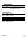
5
Ordering information ............................................................................12
6
Scope of delivery ..................................................................................13
7
Unit description.....................................................................................14
8
8.1
8.2
8.3
8.3.1
8.3.2
8.3.3
8.3.4
8.3.5
8.3.6
8.4
8.5
8.5.1
8.5.2
8.6
Installation of the Dome unit................................................................15
Tools required .........................................................................................15
Installation procedure..............................................................................16
Installing the mounting brackets .............................................................17
Wall/Ceiling mount CCDS1415-WM .......................................................17
Corner mount adapter CCDS1415-CMA ................................................18
Parapet mount adapter CCDS1415-BM .................................................19
Pendant mount CCDS1415-PM..............................................................20
Pole fixture (using wall mount CCDS1415-WM).....................................21
Recessed ceiling tile mount CCDS1415-FM ..........................................21
Preparing the Dome bracket ...................................................................23
Cat5 cable assembly and disassembly...................................................25
Assembly.................................................................................................26
Disassembly............................................................................................29
Connecting the Solaris™ Dome..............................................................30
9
9.1
9.2
9.2.1
9.2.2
9.3
9.4
9.4.1
9.4.2
9.4.3
9.5
Installation of the External Termination Unit (XTU)...........................31
Unit description .......................................................................................31
Installation procedure..............................................................................31
Choosing a location for the XTU .............................................................32
Mounting the XTU ...................................................................................32
Connecting the XTU to external equipment............................................33
Description of the connections................................................................33
XTU connections - coaxial (C-type) telemetry ........................................35
XTU connections - RS485 (D-type) telemetry ........................................36
XTU connections - Photon telemetry ......................................................37
Wiring guide ............................................................................................38
10
10.1
10.2
10.3
10.4
Configuration of the External Termination Unit.................................39
Keys and their functions..........................................................................39
LCD orientation .......................................................................................40
The XTU main menu...............................................................................40
XTU setup ...............................................................................................42
3
Siemens Building Technologies
Fire Safety & Security Products
08.2006
11
11.1
11.1.1
11.1.2
11.1.3
11.1.4
11.1.5
11.1.6
11.1.7
11.1.8
Configuration of the Dome unit ...........................................................43
On-screen display menus .......................................................................43
The Passcodes menu .............................................................................44
The Camera menu ..................................................................................45
The Presets, Tours and Patterns menu ..................................................47
The Privacy Zones menu ........................................................................49
The Soft Limits and Sectors menu..........................................................50
The Alarm menu......................................................................................51
The OSD menu .......................................................................................53
The Diagnostics menu ............................................................................54
12
12.1
12.1.1
12.1.2
12.1.3
12.2
12.3
12.3.1
12.3.2
12.4
12.4.1
12.4.2
12.5
12.5.1
12.5.2
12.5.3
12.5.4
12.5.5
12.5.6
12.5.7
Telemetry controller operation and setup ..........................................55
Telemetry keyboard operation ................................................................55
Access to the OSD with Siemens controllers..........................................55
Access to the OSD with Bewator controllers ..........................................56
Access to the OSD with 3rd party controllers .........................................56
Advanced camera functions....................................................................57
Use with Siemens controllers..................................................................57
Direct control via CKA48xx/CKA32xx .....................................................58
Control via SIMATRIX NEO and dome converter CAC0103 ..................59
Use with Bewator controllers...................................................................60
Molynx & Molynx V3................................................................................60
PCCON, PCCON 1-way and PCCON MULTIDROP ..............................61
Use with 3rd party controllers..................................................................63
Pelco P & D protocols .............................................................................63
Ernitec ERNA protocol ............................................................................64
VCL protocol............................................................................................65
Videmech Universal protocol ..................................................................65
Photon protocol .......................................................................................66
Vicon protocol .........................................................................................66
Philips protocol ........................................................................................67
13
13.1
13.2
13.3
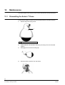
Maintenance...........................................................................................68
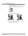
Dismantling the Solaris™ Dome .............................................................68
Monthly checks .......................................................................................69
Bubble maintenance ...............................................................................69
14
Disposal .................................................................................................70
15
Keyword index.......................................................................................71
4
Siemens Building Technologies
Fire Safety & Security Products
08.2006
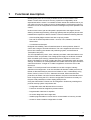
1
Functional description
Breaking away from the commonly available domes on the market the new
Solaris™ Dome offers a level of accuracy, speed and configurability never
experienced before. Solaris™ is available for both internal and external use so you
can utilise your security system to the full. Underneath the contemporary styling of
the Dome’s cover is a fully featured camera unit designed to put the operator in full
control.
Under manual control, pan and tilt speed is proportional to the degree of zoom
allowing accurate target tracking, whilst high speed preset acquisition permits near
instantaneous response to alarms. Solaris™ Domes include the following features:
– Colour and Day/Night versions both with 24 privacy masks.
– Pan and Tilt Preset acquisition within 1 second, Tours, Patterns, Preset and
Sector texts.
– 7 local alarms and tamper.
Designed with reliability, ease of install and ease of use as priorities, Solaris™
comes with a range of innovative features. The unit is supplied as two halves - the
Dome Unit containing the camera and positioning system, and the External
Termination Unit (XTU).
The XTU separates the power, video, telemetry and alarm cable terminations from
the Dome itself; and provides a low voltage power supply for the Dome contained
within a weather-proof housing. Address and protocol selection is via a menu
driven LCD display in the XTU, avoiding the issue of remembering switch and links
settings. This means, for most applications the installer need never open the Dome
camera’s enclosure. A single 10 m cable is supplied to connect the XTU to the
Dome unit.
Solaris™ is a multi-protocol Dome suitable for use with a range of industry
standard control equipment. It can be controlled via Siemens CCDA protocol over
RS485, bi-directional Molynx protocol over RS485 or coax, or alternatively using
Ernitec, Pelco D, Pelco P or VCL, Videmech Universal, Photon and PCCON
protocols over RS485. Once the receiver address, the protocol and interface have
been configured using the XTU, all other configuration can be done remotely via
the pass code protected on-screen display (OSD) menus.
Using the OSD Solaris™ Domes can be configured in flexible ways making them
powerful security system components with:
– Configurable alarm and idle state time out actions
– Functions can also be assigned to preset numbers
– Programmable video launch amplifier
– On-screen diagnostics and usage stats
– Installer programmable on-screen text for contact details or inventory number
– Access to camera module configuration via OSD
5
Siemens Building Technologies
Fire Safety & Security Products
08.2006
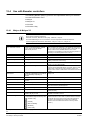
2
Safety
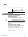
2.1
Target readers
The instructions in this document are designed only for the following target
readers:
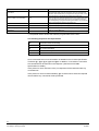
2.2
Target readers
Qualification
Activity
Condition of the
equipment
Start-up personnel
Appropriate
professional training
regarding the function
and units or systems to
be brought into
operation.
Start-up personnel bring New, installed, rebuilt
the unit or system which unit or system with
has been installed into
malfunction.
operation on-site.
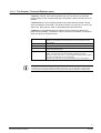
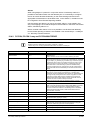
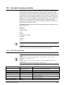
General safety precautions
– Read the general safety precautions before operating the unit.
– Follow all warnings and instructions marked on the device.
– Keep this document available for reference.
– If the product is passed on to another party, include this document.
This device must be earthed.
CAUTION
A readily accessible disconnect device shall be incorporated in the building
installation wiring.
As part of the building installation protect this device via a 3 A fuse or 3 A circuit
breaker.
The Solaris™ Dome should be installed by competent, qualified personnel in
accordance with the latest national standards.
These include:
– NACOSS National Approval Council for Security Systems
– NACP20 Code of Practice for installation and maintenance of Closed Circuit
Television Systems
– IEE Requirements for Electrical Installations, BS 7671
– UK Data Protection Act 1998 - CCTV Data Protection Codes of Practice
Radio interference with other devices in the environment
This is a Class A device. This equipment may cause radio interference in a
residential installation. In this case the user is encouraged to perform appropriate
measures to correct the interference.
6
Siemens Building Technologies
Fire Safety & Security Products
08.2006
Liability claim
– Do not connect the device if any parts are missing or damaged.
– Do not make any changes or modifications to the device that are not mentioned
in this manual and that have not been approved by the manufacturer.
– Use only spare parts and accessories that have been approved by the
manufacturer.
Damage during transport
– Keep the packaging material for future transportation.
– Do not expose the device to mechanical vibrations or shocks.
Cable damage due to mechanical load
When connecting the cables, do not apply tensile force and make sure not to bend
or damage them.
Damage due to unsuitable mounting location
– The environmental conditions recommended by the manufacturer must be
observed. See Section: 4 Technical data.
– Do not operate the device close to sources of powerful electromagnetic
radiation.
– Do not operate the device in excessively dusty places.
– Do not operate the device where it is exposed to mechanical vibrations.
Damage to the device due to overvoltage
Connect the device only to power sources with the specified voltage. Voltage
supply requirements can be found on the power supply unit/type label. See
Section: 4 Technical data.
Danger of electrical shock and damage to the device
Electrical grounding must meet the customary local safety regulations.
Data loss after update
Make sure to backup all data before updating the device.
Electric shock or fire hazard
Never insert objects through the openings on the device.
Danger of electrical shock during maintenance
Always disconnect the power cable and other cables from the main power supply
before performing maintenance.
Danger of electrical shock while cleaning the device
– Disconnect the device from the mains supply before cleaning it.
– Do not use liquid cleaners or sprays that contain alcohol, spirit or ammonia.
7
Siemens Building Technologies
Fire Safety & Security Products
08.2006
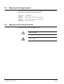
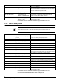
2.3
Meaning of the signal words
The severity of a hazard is indicated by the following signal words. Ignoring these
hazards may lead to the consequences indicated.
2.4
Signal word
Type of hazard
WARNING
Possible danger of death or severe bodily harm.
CAUTION
Danger of minor bodily injury or property damage
IMPORTANT
Danger of malfunctions
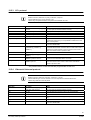
Meaning of the hazard symbols
The nature of the hazard is indicated by icons.
Dangerous situation
Electrical voltage
8
Siemens Building Technologies
Fire Safety & Security Products
08.2006
3
Guidelines and standards
3.1
EU directives
The product meets the requirements of the EU Directive 89/336/EEC on
electromagnetic compatibility The EU declaration of conformity is available from:
Siemens Building Technologies
Fire & Security Products GmbH & Co. oHG
76181 Karlsruhe, Germany
EU Directive 89/336/EEC on electromagnetic compatibility
Conformity with the European Directive 89/336/EEC is demonstrated by
compliance with the following standards:
Emitted interference:
EN 61000-6-3
Resistance to
interference:
EN 50130-4
EN 55022 Class B
EU Directive 73/23/EEC „Low-Voltage Directive”
Compliance with the European Directive 73/23/EEC has been proven by testing
according to the following standard:
Safety:
3.2
EN 60950-1
FCC compliance
This equipment has been tested and found to comply with the limits for a Class A
digital device, pursuant to Part 15 of the FCC Rules. These limits are designed to
provide reasonable protection against harmful interference when the equipment is
operated in a commercial environment.
This equipment generates, uses, and can radiate radio frequency energy and, if
not installed and used in accordance with the instruction manual, may cause
harmful interference to radio communications.
Operation of this equipment in a residential area is likely to cause harmful
interference and the user may be required to correct this. Shielded cables should
be used with this unit to ensure compliance with class A limits.
9
Siemens Building Technologies
Fire Safety & Security Products
08.2006
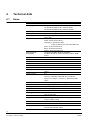
4
Technical data
4.1
Dome
Electrical
Camera types
Input voltage XTU
In-rush current XTU
Input voltage Dome unit
Connections
Electromagnetic
compatibility
Operational
Pan speed
Pan travel
Tilt speed
Tilt travel
Presets
Tours
Preset accuracy
Control hardware
XTU video output
Relay contact rating
Alarm input
Mechanical
Application
Mounting
18x optical Colour (PAL): CCDS1415-ST
18x optical Day/Night (PAL): CCDS1415-DN
26x optical Day/Night (PAL): CCDS1415-DNX
110 – 230 V AC @ 50 / 60 Hz, 1 A max.
40 A / 20 A peak @ 110 / 230 V AC
18-24 V DC @ 2 amp, supplied from the XTU via the
Cat-5 cable
Video: BNC coax
Power: Screw terminal block
Telemetry: C type(Coax): BNC
D type (Twisted Pair): Screw terminal block
Alarm: Screw terminal block
Relay: Screw terminal block
Photon: Screw terminal block
Compliant with EMC directive 89/336/EC.
Conforms to Part 15 of the FCC Rules, Class A digital
device
0.2-360°/sec
360° continuous
0.2-360°/sec
+10° and -100°
99
32 positions, fully programmable for sequence, dwell and
speed
0.3°
SIMATRIX NEO, SIMATRIX SYS/648/164 via CAC0103,
CKA3210, CKA4820, SISTORE AX, CX, MX, SX,
Visilynx V3i, Visilynx II, Visilynx 2+, 6000 series, 600
series,
Nominal (no gain) VBS 1.0 Vp-p (sync negative)
1.5 A @ 24 V DC
Opto-coupled (short to alarm com.)
Indoor or outdoor - all models
Wall/fixed ceiling, corner, wall top, pendant, pole, swan
neck or ceiling tile
Pendant mount size/thread Standard 1.5” BSP (parallel)
Weight
Boxed 5.6 kg, XTU only (no cables) 1.5 kg, DOME UNIT
only (no cables) 2.5 kg
Ext. construction
Injection moulded polycarbonate (GE Lexan EXL9335)
Colour
Pure white RAL9010
Bubble
Smoked: CCDS1415-ST
Clear:CCDS1415-DN / -DNX
10
Siemens Building Technologies
Fire Safety & Security Products
08.2006
Environmental
Operating temperature
IP 67
-10 to +40 °C (-20°C after unit has been powered up for
3 hours)
-20 to +60 °C
50,000 hrs (electric parts)
Storage temperature
MTBF
All specifications are subject to change without prior notice.
4.2
Camera module
CCDS1415-DNX
Image sensor
CCDS1415-DN
1/4” type IT CCD (EX View HAD)
Effective pixels PAL
430k
Resolution PAL
Lens
480 TV lines
26 x zoom 3.5 mm to
91 mm (F1.6 to F3.8)
18 x zoom 4.1 mm to 73.8 mm
(F1.4 to F3.0)
Digital zoom
Angle of view
Minimum object distance
Minimum illumination
12 x
2.2° (tele) to 54.2° (wide)
2.7° (tele) to 48° (wide)
320 mm (wide end),
1500 mm (tele end)
290 mm (wide end),
800 mm (tele end)
0.05 lux (colour)
0.01 lux (mono)
S/N ratio
Electronic shutter
White balance
Gain
Focusing system
Privacy zones
CCDS1415-ST
0.05 lux (colour)
>50 dB
1/10000 s, 22 steps
1/1 to 10000 s, 22 steps
Auto/One Push
Auto (-3 to 28 dB, 2 dB steps)
Manual/automatic
24
11
Siemens Building Technologies
Fire Safety & Security Products
08.2006
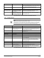
5
Ordering information
Type
Part. No.
Designation
CCDS1415-DNX
2GF1194-8AD
¼" high-resolution Dome, 24 privacy zones, x26 zoom, colour/mono, clear
bubble, IP67, supplied with 110 – 230 V AC XTU
CCDS1415-DN
2GF1194-8AC
¼" high-resolution Dome, 24 privacy zones, x18 zoom, colour/mono, clear
bubble, IP67, supplied with 110 – 230 V AC XTU
CCDS1415-ST
2GF1194-8AA
¼" high-resolution Dome, 24 privacy zones, x18 zoom, colour, smoked
bubble, IP67, supplied with 110 – 230 V AC XTU
CCDS1415-DH
2GF1194-8BA
Dummy Dome, IP67 (no camera or XTU)
CCDS1415-CH
2GF1194-8BB
Dome Housing for box camera, IP67 (no camera or XTU)
Accessories, not included in the delivery!
CCDS1415-PM
2GF1194-8CA
Pendant mount
CCDS1415-FM
2GF1194-8CB
Recessed ceiling tile mount
CCDS1415-SN
2GF1194-8CC
Swan neck bracket
CCDS1415-WM
2GF1194-8CD
Wall /ceiling mount
CCDS1415-CMA 2GF1194-8CE
Corner mount adapter
CCDS1415-BM
2GF1194-8CF
Parapet mount adapter
CCDS1415-RTU
2GF1194-8CG
Remote Termination Unit (RTU)
CCDS1415-XTU
2GF1194-8BC
External Termination Unit (XTU)
CCDS1415-BC
2GF1194-8BD
Clear bubble
CCDS1415-BS
2GF1194-8BE
Smoked bubble
Spare parts
12
Siemens Building Technologies
Fire Safety & Security Products
08.2006
6
Scope of delivery
Prior to installation confirm that the following are in the box:
z 1 x Solaris™ Dome unit
z 1 x External Termination Unit (XTU)
z 1 x Dome connection cable (Cat 5) with weatherproof connector
z 1 x installation manual
z 1 x cable gland pack (for XTU)
z 4 x cable ties (for XTU cable management)
z 5 mm AF Allen key
z 1.5” BSP knurled locking nut
z 2 x extra cable ties for connection cable
z Printed mounting instructions
z CD containing detailed configuration manuals
13
Siemens Building Technologies
Fire Safety & Security Products
08.2006
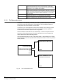
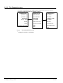
7
Unit description
A complete Solaris™ Dome system consists of a single sealed Dome unit
(containing a camera fitted to a pan and tilt mechanism), connected by a Cat-5
cable to an External Termination Unit (XTU). The XTU contains a PSU and a PCB
fitted with a variety of interface connection terminals.
The installation of a Solaris™ Dome consists of two parts:
z the installation of the Dome unit and
z the installation of the XTU.
The following chapter is concerned with the first of these. It will take you step by
step through the various types of installation.
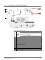
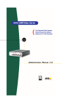
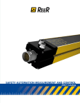
Fig. 1
Parts of the Solaris™ Dome
1
Mounting bracket (fixed horizontally or vertically)
2
Hinged bracket assembly
3
Dome
4
Bubble
5
1.5" BSP mounting thread
6
Screw for hinge assembly
14
Siemens Building Technologies
Fire Safety & Security Products
08.2006
8
Installation of the Dome unit
Before commencing use of the Solaris™ system, ensure the following has been
completed:
1.
Ensure you have the correct tools to complete the installation, (see Section
8.1: Tools required).
2.
Install the desired bracket in a suitable location, (see Sections 8.3.1 to 8.3.6).
3.
Prepare the Dome bracket and attach it to the appropriate mounting bracket,
(see Sections 8.4: Preparing the Dome bracket and 0: Mounting the Dome
bracket to a wall mount ).
4.
Assemble the Cat5 cable (see Section 8.5: Cat5 cable assembly and
disassembly).
5.
Hook the Dome on to the hinge mechanism and connect the cable, clipping it
in place (ensure that it is correctly and firmly seated on the connector). Pull
the Dome into the vertical position (see Section 8.6: Connecting the Solaris™
Dome).
6.
Check the bubble and ensure there are no scratches on the surface. If the
surface is marked, it may impair optical clarity.
7.
Select a suitable location and mount the XTU, (see Sections 9.2.1: Choosing
a location for the XTU and 9.2.2: Mounting the XTU).
8.
Connect the XTU to any external equipment, (see Section 9.3: Connecting the
XTU to external equipment).
9.
If necessary, adjust the orientation of the XTU’s LCD display, (see Section
10.2: LCD orientation).
10. Configure the XTU to use the correct telemetry protocol and to identify itself
correctly, (see Section 10.3: The XTU main menu).
11. Setup the controller, (see Section 12: Telemetry controller operation and
setup and the controller’s installation and commissioning manual).
8.1
Tools required
Installing the Dome unit and the External Termination Unit requires only a basic
tool kit, including:
z 3 mm AF Allen key (supplied with ceiling mounting kit)
z Medium sized Pozidrive screwdriver
z Terminal screwdriver (flat-bladed)
z RJ-45 crimping tool (only if custom Dome to XTU cable is used)
z Suitable tools for chosen fasteners for fitting bracketry and mounting the XTU
z Suitable tools to install the required cabling and connections
CAUTION
Handle the bubble of the Solaris™ Dome with extreme care and be sure not to
scratch it, as this may affect its optical clarity. If it is accidentally marked it may
be possible to remove small scratches or scuffs on the outer surface with the
use of a suitable cloth and metal polish (brass cleaner). However, if this is not
effective the bubble must be replaced.
15
Siemens Building Technologies
Fire Safety & Security Products
08.2006
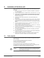
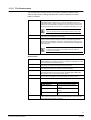
8.2
Installation procedure
The two-piece mounting bracket and the hinge mechanism built into the Dome
casing make the physical installation very simple.
Making the electrical connections is just as simple. All of these are provided via a
single connector fitted to the Cat-5 cable supplied.
This just needs to be plugged in and clipped in place before the Dome casing is
closed and fixed with a single screw. This combination ensures quick installation of
the Dome.
Installation using the recessed ceiling tile mount utilises a simplified fixing
procedure compared to other Domes and the electrical connections are just as
simple as with the bracket and pendant mounted units.
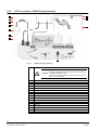
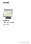
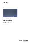
Fig. 2
Cross-sectional view of the Solaris™ Dome
To install the dome unit, proceed as follows:
1.
First install the appropriate mounting bracket. See Section 8.3: Installing the
mounting brackets.
2.
Prepare the Dome bracket. See Section 8.4: Preparing the Dome bracket.
3.
Route the cable through the Dome bracket. See Section 8.5: Cat5 cable
assembly and disassembly.
4.
Connect the cable to the Dome unit. See Section 18.6: Connecting the
Solaris™ Dome.
5.
Attach the Dome to the Dome bracket.
16
Siemens Building Technologies
Fire Safety & Security Products
08.2006
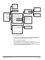
8.3
Installing the mounting brackets
There are several types of brackets to choose from – wall/ceiling mount, corner
mount adapter, parapet mount adapter, pendant mount, swan-neck bracket and
recessed ceiling tile mount.
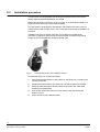
8.3.1
Wall/Ceiling mount CCDS1415-WM
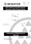
Fig. 3
Ceiling mount
Fig. 4
Wall mount
Fig. 5
Wall / ceiling mount
1.
Bolt the wall/ceiling mount to the mounting substrate using the four mounting
holes shown.
NOTE
Ensure the chosen fasteners and fastening method are suitable for the application and the mounting
substrate.
17
Siemens Building Technologies
Fire Safety & Security Products
08.2006
Cable exits
1
1
Rear of plate
1
1
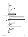
8.3.2
M25 electrical conduit threaded cable
exit on the underside of the bracket
Corner mount adapter CCDS1415-CMA
1.
Using 3 x M8 nuts and M8 x 20 bolts fasten the wall mount bracket to the
corner mount adapter as shown below.
2.
Fasten the corner mount adapter to the mounting substrate using the eight
holes shown.
NOTE
Ensure the chosen fasteners and fastening method are suitable for the application and the mounting
substrate.
Fig. 6
Wall bracket in conjunction with corner mount adapter
Fig. 7
Solaris™ Dome mounted to wall bracket and corner mount adapter
18
Siemens Building Technologies
Fire Safety & Security Products
08.2006
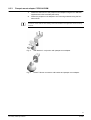
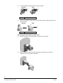
8.3.3
Parapet mount adapter CCDS1415-BM
1.
Fasten the wall mount to the parapet mount adapter using the four M8 bolts
supplied with CCDS1415-BM (see below).
2.
Fasten the parapet mount adapter to the mounting substrate using the four
holes shown.
NOTE
Ensure the chosen fasteners and fastening method are suitable for the application and the mounting
substrate.
Fig. 8
Wall bracket in conjunction with parapet mount adapter
Fig. 9
Solaris™ Dome mounted to wall bracket and parapet mount adapter
19
Siemens Building Technologies
Fire Safety & Security Products
08.2006
8.3.4
Pendant mount CCDS1415-PM
The pendant mount CCDS1415-PM is supplied with a 1.2 m pole.
1.
Cut the unthreaded end of the pole to the desired length.
2.
Slide the pole into the top of the mounting flange until level with the top face of
the flange.
3.
Spot drill the pole through the holes in the mounting flange.
4.
Remove the pole and drill through both sides of the pole with a 9 mm drill.
5.
Re-insert the pole and secure it using two M8 x 60 screws provided with the
pendant mount.
6.
Fasten the mounting flange to the mounting substrate using the three holes
shown.
NOTE
Ensure the chosen fasteners and fastening method are suitable for the application and the mounting
substrate.
Fig. 10
Pendant mount
20
Siemens Building Technologies
Fire Safety & Security Products
08.2006
8.3.5
Pole fixture (using wall mount CCDS1415-WM)
The wall mount CCDS1415-WM has four 12 mm square holes through the
mounting plate. These holes are to pass 11 mm continuous banding through as
shown.
NOTE
Ensure the chosen fasteners and fastening method are suitable for the application and the mounting
substrate.
Fig. 11
8.3.6
Pole mounting
Recessed ceiling tile mount CCDS1415-FM
The Solaris™ Dome can be installed in a standard false ceiling tile using the
recessed ceiling tile mount. The recessed ceiling tile mount consists of two
accessory mounting brackets that are fixed to the Solaris™ Dome, and two Uchannel brace bars which are secured to the ceiling support framework. The brace
bars are suitable for use with both 600x600 mm and 600x1200 mm ceiling tile
systems.
To install the recessed ceiling tile mount you will need access to the top of the tile
from one or more adjacent tiles.
Install using the recessed ceiling tile mount as follows:
1.
Prepare the ceiling tile by cutting a 235 mm diameter hole in the centre (using
the template provided) and then fit it back in place in the ceiling support
frame.
2.
Remove the six screws holding the Solaris™ Dome's bezel in place and
remove the bezel.
NOTE
Handle the bubble of the Solaris™ Dome with extreme care and be sure not to scratch it, as this may
affect its optical clarity.
3.
Fit the ceiling mount accessory brackets in place using the four self-tapping
screws provided.
21
Siemens Building Technologies
Fire Safety & Security Products
08.2006
4.
Refit the bezel; tighten the six screws lightly to begin with, and then fully
tighten each in turn.
NOTE
Ensure that the six screws are sufficiently tight to compress the bubble seal (recommended torque
setting 1.2 - 1.3 Nm).
5.
Fit the brace bars to the accessory brackets using the support screws
provided.
NOTE
The recessed ceiling tile mount is for use with standard thickness ceiling tiles. If using non-standard
thickness ceiling tiles, it may be necessary to use different support screws (not supplied) to mount the
brace bars onto the accessory brackets.
22
Siemens Building Technologies
Fire Safety & Security Products
08.2006
6.
Lower the complete assembly into place, allowing the Dome to pass through
the hole in the ceiling tile.
7.
Ensure that the brace bar is correctly located on the support framework and
then fix it using the screws provided.
8.
Fit the supplied bezel.
NOTE
The Dome can be lowered or raised depending on the situation by adjusting the height of the support
screws.
9.
Connect the cable connector to the socket.
Î
8.4
The ceiling tile installation is now complete.
Preparing the Dome bracket
The Dome bracket is provided with a standard 1.5" BSP thread and stainless steel
lock nut to enable it to be used with a range of standard mounting hardware. The
bracket is constructed of two parts, which can be turned in respect of each other to
allow for a vertical or horizontal mounting arrangement.
To prepare the bracket for mounting the Dome:
1.
Orientate the two parts of the bracket correctly.
23
Siemens Building Technologies
Fire Safety & Security Products
08.2006
2.
Fix them together using the three screws provided.
Pendant
1, 2
3.
Wall
1
1
2
2
Screw
Screw the bracket on to the end of the mounting tube, locking into place with
the grub screw.
Pendant
Wall
1
1
1
Screw
Mounting the Dome bracket to a wall mount
4.
Screw the locknut onto the bracket, to the back of the thread.
5.
Screw the Dome bracket onto the wall mount and position it correctly. A
minimum of four turns will be sufficient.
24
Siemens Building Technologies
Fire Safety & Security Products
08.2006
6.
8.5
Lock the Dome bracket into position by back-tightening the locknut and
locking it against the face of the Dome bracket. Hand tight will be sufficient.
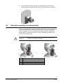
Cat5 cable assembly and disassembly
Solaris™ is supplied with a 10 m preassembled Cat 5 cable. In some cases, it may
be necessary to change the cable (for a shorter cable or to replace a damaged
cable, for example). It is very important that the cable assembly is assembled /
disassembled in the following manner, to ensure a watertight seal between the
connector and the Dome unit.
IMPORTANT
1
Label
2
Seal 2
3
Seal 1
4
Connector
5
Spring-clip
The Solaris™ Dome will not be fully water protected if these vital checks are
not made prior to finalising the installation.
25
Siemens Building Technologies
Fire Safety & Security Products
08.2006
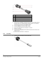
1
Compression Clamp
2
Plastic Washer
3
Connector Body
4
Cat 5 Cable Assembly
5
Rubber Washer
5
Rubber Washer
6
Locking Nut
1.
Ensure that the connector is assembled as per the overview below. Ensure
that the locking nut is sufficiently tight to seal the assembly. Full assembly
instructions can be found in the Installation Manual.
2.
Ensure that Seal 1 is present and fitted correctly.
3.
Ensure that Seal 2 is present and fitted correctly.
4.
Remove the Label adhered to the Solaris™ connector.
5.
Make the connection.
6.
Ensure that the spring-clip securely fastens and locks the connector to the
Solaris™ Dome.
Î
8.5.1
This will ensure that Solaris™ is waterproof
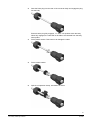
Assembly
1.
Pass the connector locking nut over the RJ45 plug.
26
Siemens Building Technologies
Fire Safety & Security Products
08.2006
2.
Pass the RJ45 plug from the rear of the connector body and engage the plug
into the body.
Ensure that the plug fully engages, i.e. ‘clicks’ into position within the body.
When fully engaged, the cable will not be able to be retracted from the body
when pulled.
3.
Fit the plastic washer. Take care not to damage the cable.
4.
Fit the rubber washer.
5.
Split the compression clamp, orientation as shown.
27
Siemens Building Technologies
Fire Safety & Security Products
08.2006
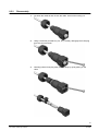
6.
Clamp around the cable. Take care not to damage the cable.
7.
Complete the connector assembly by sliding all parts into the connector body
and hand tightening the locking nut. Sufficient force must be applied to the
locking nut to compress the rubber washer, thus sealing the assembly. When
sufficiently tight hold the assembly to a light source; if correctly sealed, light
will not be seen though it. If light can be seen, hand tighten with more force.
8.
Finally, loop the cable as shown.
9.
Lock the cable in position with the cable tie provided. This ‘loop and tie’ will
divert water that runs down the cable away from the connector assembly.
28
Siemens Building Technologies
Fire Safety & Security Products
08.2006
8.5.2
Disassembly
1.
Cut away the cable tie and un-loop the cable. Unscrew the locking nut.
2.
Using a small tool (screwdriver, pen, etc.) carefully disengage the RJ45 plug
from the connector body.
3.
Carefully pull the RJ45 plug away from the body by gently pulling on the
cable.
29
Siemens Building Technologies
Fire Safety & Security Products
08.2006
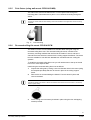
8.6
Connecting the Solaris™ Dome
1.
Offer the Dome up to the mounting bracket and hook it on to the hinge
mechanism. The hinge should now take the weight of the Dome, leaving your
hand free to make the connection.
2.
Remove the dust cap. It is held to the unit with a lanyard so it will not be
misplaced. Position the dust cap loosely to the side of the bulkhead
connector.
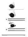
3.
Feed the cable through the opening.
4.
Fit the connector’s locking clip to ensure a watertight seal.
5.
Pull the Dome unit into the vertical position (taking care that the cable doesn’t
snag) and lock it into place with the fixing screw.
Î
The installation of the Dome is now complete.
30
Siemens Building Technologies
Fire Safety & Security Products
08.2006
9
Installation of the External Termination Unit (XTU)
This chapter covers the physical and electrical installation of the Solaris™ Dome’s
External Termination Unit (XTU).
NOTE
The XTU is patent pending.
9.1
Unit description
The External Termination Unit (XTU) is an IP67 sealed enclosure containing the
Dome unit's power supply, telemetry interface, alarm/relay connections, video
conditioning and protocol conversion.
The advantages of this separate XTU enclosure include:
z Ease of setup and installation of the Dome unit
z Single connection cable to the Dome unit
z All other connections are made to the XTU
z Ease of access for maintenance
The XTU allows the Dome to be controlled via:
z Coaxial telemetry (see Section 9.4.1: XTU connections - coaxial (C-type)
telemetry).
z RS485 telemetry (see Section 9.4.2: XTU connections - RS485 (D-type)
telemetry).
z Photon telemetry (see Section 9.4.3: XTU connections - Photon telemetry).
9.2
Installation procedure
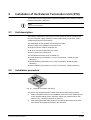
Fig. 12
External Termination Unit (XTU)
The XTU is very straightforward to install; these are the basic steps required:
1.
Select a suitable location for the installation to allow the most suitable access
to the required cabling (power, telemetry, alarms etc.) and the Dome. See
Section 9.2.1: Choosing a location for the XTU.
2.
Select the appropriate cable glands for the cabling/connections to be used
and remove the required knockouts in the enclosure.
31
Siemens Building Technologies
Fire Safety & Security Products
08.2006
3.
Mount the XTU in the selected position and orientation using appropriate
fasteners for the mounting substrate. See Section 9.2.2: Mounting the XTU.
4.
Set the RS485 termination resistor if required.
5.
Route and connect all of the required cabling to the XTU (use the supplied
special M20 split rubber cable gland for the Dome connection cable)
6.
Power up the XTU.
7.
Orientate the LCD display to suit the mounted position.
8.
Set-up the XTU to operate correctly with your chosen controller, set the
protocol (e.g. MOLYNX V3), set the interface (e.g. RS485 or Coax control),
set the receiver address (e.g. camera '1'). See Section 12: Telemetry
controller operation and setup.
9.
key, the XTU LCD should display a digitised
Optional video test. Press the
view of what the Dome camera is pointing at.
Press the
key to resume normal operation.
10. After the XTU has been fully set-up fit the lid on the XTU securely using the 4
lid mounting screws to ensure a weatherproof seal.
9.2.1
Choosing a location for the XTU
The XTU should be located in a position which allows the most suitable and
convenient routing and connection of the required cabling. Factors to consider are
the proximity to the Dome unit (10 m cable supplied as standard, extendable to
30 m maximum), power supply, connections to telemetry controller, alarms and the
security/protection of the chosen location. The XTU is fitted with a tamper switch
that is activated upon opening of the enclosure, but the enclosure itself is not
tamper-proof.
If a cable longer than 10 m is required, it can be increased to 30 m maximum,
using Cat-5e UTP 4 pair 24 AWG type cable. Ensure the correct coloured wires are
wired to the correct pins (see Section 9.5: Wiring guide).
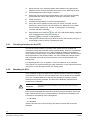
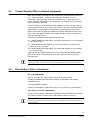
9.2.2
Mounting the XTU
Once a suitable location has been found, mark the positions of the four mounting
holes at 235 mm x 160 mm. The mounting holes in the enclosure have a diameter
of 4.5 mm, so select fasteners to suit this and drill holes to match the chosen
fasteners and mounting substrate. The head of the fasteners used should not
exceed 9 mm in diameter.
IMPORTANT
To ensure that the unit is weatherproof (IP67) the cable glands must point
downwards.
Remove the required gland knockouts by punching through the plastic around the
edge of the knockouts using a small screwdriver. Knockouts are available in the
enclosure for the following metric cable glands:
– 7 x M12/M20
– 2 x M16/M25
Offer the enclosure up to the mounting holes and fix in place with the chosen
fasteners.
32
Siemens Building Technologies
Fire Safety & Security Products
08.2006
9.3
Connecting the XTU to external equipment
Make the necessary connections to the XTU referring to the diagrams in Section
9.4.1: XTU connections - coaxial (C-type) telemetry, Section 9.4.2: XTU
connections - RS485 (D-type) telemetry, and Section 9.4.3: XTU connections Photon telemetry, depending on your installation, the markings on the XTU PCB
and the connection list below.
These connections will vary between each installation, and as such there will be
varying requirements for the number of connections, connection type and sealing
requirements. It is the installer's responsibility to ensure that the correct cable
glands are used for the cable type utilised to provide a weatherproof seal. The IP
class of the cable glands used for cable entries should be higher or the same as
that of the enclosure (IP67).
A selection of cable glands are supplied with the XTU:
z 1 x M20 standard IP68 cable gland - for cables with diameter 10-14 mm (tighten
to 3.3 Nm for IP68).
z 1 x M20 special IP68 cable gland - for use with the Dome connection cable
(tighten to 3.3 Nm for IP68).
z 2 x M12 standard IP68 cable glands - for cables with diameter 3-6 mm (tighten
to 1.7 Nm for IP68).
Cable ties are also supplied with the XTU to be used to provide additional strain
relief for the cables by securing them to the punched out anchors in the XTU
mounting plate.
NOTE
All wiring to the XTU should be carried out by a qualified installer and conform to local regulations.
9.4
Description of the connections
AC input [REQUIRED]
Must be 110-230 V AC, use the strain relief to secure mains cable.
A readily accessible disconnect device shall be incorporated in the building
installation wiring.
This device must be earthed.
As part of the installation protect this device via a 3 A fuse or 3 A circuit breaker.
Coax cable to controller [REQUIRED]
Connect to the controller, video and C-type telemetry pass through this connection.
The cable should be a 75 Ohm CCTV cable URM70, RG59, CT125, etc.
NOTE
The higher the quality of the cable, the further the XTU can be from the controller whilst maintaining
good video quality.
33
Siemens Building Technologies
Fire Safety & Security Products
08.2006
Dome connection cable [REQUIRED]
The supplied Dome connection cable is 10 m long, and is fitted at both ends with a
standard RJ45 connector. The Dome end should be connected using the supplied
weatherproof connector, the XTU end should be connected to the RJ45 connector.
A special split rubber M20 cable gland for use on the XTU end of the Dome
connection cable is supplied, this allows a weatherproof seal to be made on the
cable without having to pass the RJ45 connector through the sealing rubber. See
Section 9.5: Wiring guide.
Twisted pair from controller [OPTIONAL]
D-type (RS485) telemetry should be connected to this terminal, the cable type
should be a suitable twisted-pair cable 100-120 Ohms designed for high-speed
communication purposes, e.g. Belden 8205.
The two extremities of the RS485 network should be terminated. Generally this will
be the last Dome and the control equipment. LNK1 on the XTU will perform
termination and should be either ‘made’ which is terminated or ‘open’ which is unterminated.
Alarm contacts [OPTIONAL]
Connection to these alarm inputs must be from volt free contacts, connect from
ALM1 to COM, ALM2 to COM, …, ALM7 to COM as shown in the XTU connection
diagram. Example use - point the Dome camera module to a chosen preset when a
PIR device is triggered.
Relay outputs [OPTIONAL]
Use the outputs COM to N/O and/or N/C to control an auxiliary device, such as an
alarm system.
Warning: 1.5 A, 24 V DC max.
2-core telemetry cable from Photon controller [OPTIONAL]
Connect to this terminal if Photon telemetry is to be used (not polarised).
34
Siemens Building Technologies
Fire Safety & Security Products
08.2006
9.4.1
XTU connections - coaxial (C-type) telemetry
Fig. 13
Coaxial (C-type) telemetry
1
This device must be earthed.
CAUTION
A readily accessible disconnect device shall be incorporated in
the building installation wiring.
As part of the building installation protect this device via a 3 A
fuse or 3 A circuit breaker.
2
AC mains Input
3
AC mains to PSU
4
Alarm contacts
5
Relay output to user equipment (e.g. alarm system) 1.5 A, 24 V DC max.
6
Interface connector (do not use)
7
Tamper switch
8
From PSU
9
Programming header (do not use)
10
Telemetry indicator
11
Coax cable (video to & telemetry from controller)
12
Dome unit
13
Dome connection cable
14
Camera input / telemetry output
15
Telemetry controller
35
Siemens Building Technologies
Fire Safety & Security Products
08.2006
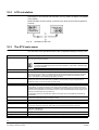
9.4.2
XTU connections - RS485 (D-type) telemetry
Fig. 14
RS485 (D-type) telemetry
1
This device must be earthed.
CAUTION
A readily accessible disconnect device shall be incorporated in
the building installation wiring.
As part of the building installation protect this device via a 3 A
fuse or 3 A circuit breaker.
2
AC mains input
3
AC mains to PSU
4
Alarm contacts
5
Relay output to user equipment (e.g. alarm system) 1.5 A, 24 V DC max.
6
Interface connector (do not use)
7
Tamper switch
8
From PSU
9
Programming head (do not use)
10
Telemetry indicator
11
RS485 telemetry termination link
12
Coax cable (video to controller)
13
Twisted pair telemetry cable
14
Dome unit
15
Dome connection cable
16
Camera input
17
Telemetry controller
18
RS 485 telemetry output
36
Siemens Building Technologies
Fire Safety & Security Products
08.2006
9.4.3
XTU connections - Photon telemetry
Fig. 15
Photon telemetry
1
This device must be earthed.
CAUTION
A readily accessible disconnect device shall be incorporated in
the building installation wiring.
As part of the building installation protect this device via a 3 A
fuse or 3 A circuit breaker.
2
AC mains input
3
AC mains to PSU
4
Alarm contacts
5
Relay output to user equipment (e.g. alarm system) 1.5 A, 24 V DC max.
6
Interface connector (do not use)
7
Tamper switch
8
From PSU
9
Programming head (do not use)
10
Telemetry indicator
11
Coax cable (video to controller)
12
2-core telemetry cable
13
Dome unit
14
Dome connection cable
15
Photon telemetry controller
16
Camera input
17
Telemetry output
37
Siemens Building Technologies
Fire Safety & Security Products
08.2006
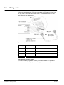
9.5
Wiring guide
If you have chosen to use a longer cable than the one supplied with the XTU,
ensure that the following pin-outs and colour coding are maintained. Failure to do
so may result in the malfunction of the Solaris™ Dome. See Section 8.5: Cat5
cable assembly and disassembly.
Fig. 16
Wiring of the XTU
XTURJ45 pins
Wire colour
Pin function
Dome unit RJ45 pins
1
White and orange
RS485 + A
1
2
Orange
RS485 - B
2
3
White and green
Differential video
3
4
Blue
DC + (18 V)
4
5
White and blue
DC + (18 V)
5
6
Green
Differential video +
6
7
White and brown
DC 0 V
7
8
Brown
DC 0 V
8
RJ45 plug part reference guide
For solid core cable (e.g. Belden 11700A), use AMP5-569278-4 or equivalent.
Ensure that a suitable crimping tool is used (e.g. Telemaster 30-496).
38
Siemens Building Technologies
Fire Safety & Security Products
08.2006
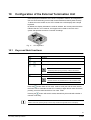
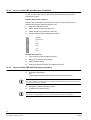
10
Configuration of the External Termination Unit
Once the physical installation of the XTU is complete it needs to be configured to
use the correct telemetry protocol and receiver address to identify itself correctly.
To allow this to be carried out, the XTU is fitted with a LCD display and a simple
keyboard.
By default, the display indicates the receiver address, the current protocol and the
interface that is in use. However, the keypad can be used to control a menu
system that provides access to a number of settings.
Fig. 17
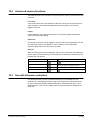
10.1
XTU keyboard
Keys and their functions
Keys
Functions
Used to enter a menu or select an option.
Scrolls through the available options.
Navigates between options.
NOTE
The left key allows you to go back up a level in the menus.
Switches the display into ‘live video’ mode for test purposes.
NOTE
Camera control is not possible when in LCD ‘live video’ mode.
Press the
button when in ‘live video’ mode to enter pan and tilt mode, where
the Dome can be controlled via the XTU. Pressing it again allows zoom and focus,
pressing a 3rd time switches back to ‘live video’ mode.
button will exit this mode; alternatively this mode will exit after 2
Pressing the
minutes of inactivity.
NOTE
Whilst in this mode, pressing the Up or Down keys will alter the brightness of the LCD display.
39
Siemens Building Technologies
Fire Safety & Security Products
08.2006
10.2
LCD orientation
Depending on how the XTU was mounted, you may need to change the orientation
of the display.
While the status screen is shown, press the up or down arrow on the keypad for 3
seconds.
Fig. 18
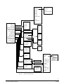
10.3
Orientation of the LCD
The XTU main menu
The XTU main menu provides access to the configuration settings in the XTU unit.
Protocol
Selects a telemetry protocol from the list.
Interface
Selects a telemetry interface from the list. Note that the Auto search option is only available when a
Molynx protocol has been selected.
NOTE
The options available depend upon the protocol selected. An option that is ‘striked-through’
will not be selectable.
Receiver address
Each unit on the system must have a unique address, selectable between 1 and 512.
Advanced comms
Allows individual comms parameters (baud rate, data bits, parity, data direction) to be altered from the
default for the current protocol. If non-default settings are being used the protocol name on the status
screen is suffixed with '*'. Selecting a protocol will set all the comms settings to the default for that
protocol. The default for each setting is indicated by an arrow.
Special presets
To allow access to the on-screen display when using a 3rd party controller, a preset may be assigned.
Recalling this preset will enter OSD mode. In addition, a second preset may be assigned which if
recalled twice within 2 seconds will enter the OSD mode.
LCD contrast
Adjust the LCD display contrast to make it more readable in difficult lighting situations.
Video gain > XTU video gain
If very long coax cable runs are used, video degradation is possible, and particularly noticeable as loss
of sharp edges. To combat this Solaris™ has internal video amplifiers, which control the video signal
amplitude of both brightness (low frequency amplification) and sharpness (high frequency lift). The high
frequencies are emphasised by the sharpness control, as they relate particularly to sharp edges which
suffer the worst attenuation on long cable runs.
The brightness control will compensate for different coax types as they have different low frequency
characteristics.
Video gain > RTU video gain
When a RTU (Remote Termination Unit) is in use this setting allows additional gain to be set to
compensate for Cat5 cable lengths in excess of 150 m.
Dome functions
Allows Pan/Tilt/Zoom and Focus control of the Dome camera and access to the OSD set-up menus.
Temperature
Displays the XTU’s current on-board temperature.
Backup/restore
All Dome settings such as camera setup, presets, tours, patterns, privacy zones and text can be backed
up to the XTU and restored at a later date if the Dome is switched with another or replaced.
Line break action > TTY mode When checked (on) a line break on the telemetry port will force the XTU into TTY mode.
[Down key] = checked (on)
[Up key] = unchecked (off)
Software info
Displays the software's version details.
Factory reset
Resets the XTU configuration back to the factory default settings.
Test mode
Opens the test menu.
40
Siemens Building Technologies
Fire Safety & Security Products
08.2006
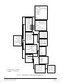
PROTOCOL
MOLYNX
BEWATOR
MOLYNX V3
ERNITEC
PCCON
PELCO D
PCCON MULTIDROP
PELCO P
EXIT
PHILIPS
PHOTON
SIEMENS CCDA
VCL
VICON
VIDEMECH UP
XTU MAIN MENU
INTERFACE
TTY
AUTO SEARCH
EXIT
CO-AX (C)
PROTOCOL
1200
RS485 (D)
INTERFACE
2400
RS485 -/+
RECEIVER ADDRESS
4800
EXIT
ADVANCED COMMS
SPECIAL PRESETS
LCD CONTRAST1
VIDEO GAIN
9600
RECEIVER ADDRESS
19200
1-512
EXIT
ADVANCED COMMS
HU FUNCTIONS
7-BITS
BAUD RATE
TEMPERATURE
8-BITS
DATA BITS
BACKUP/RESTORE
9-BITS
PARITY
LINE BREAK ACTION
EXIT
DIRECTION
SOFTWARE INFO
EXIT
FACTORY RESET
TEST MODE
NONE
SPECIAL PRESETS
ODD
OSD 1-PRESS
EVEN
OSD2-PRESS
EXIT
EXIT
1-WAY
VIDEO GAIN
2-WAY
XTU VIDEO GAIN
EXIT
RTU VIDEO GAIN
EXIT
HU FUNCTIONS
TEST MENU
PTZF
ALARMS
OSD SETUP
RELAY
EXIT
LCD
BACKUP/RESTORE
BACKUP(HU->XTU)
TELEMETRY (C)
BACKUP HU->XTU
RESTORE(XTU->HU)
EXIT
EXIT
TELEMETRY (D)
HU TELEMETRY
RESTORE XTU->HU
LINE BREAK ACTION
TTY MODE
ALARMS TEST
Menu
PHOTON
TELEMETRY
PTZF
SOFTWARE INFO
E2PROM
XTU VERSION
FACTORY TEST
HU VERSION
FACTORY TEST
RESULTS
EXIT
EXIT
Fig. 19
The XTU main menu
41
Siemens Building Technologies
Fire Safety & Security Products
08.2006
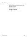
10.4
XTU setup
Using the main XTU menu you can configure the XTU to the correct settings for
your control equipment:
1.
Select the correct telemetry protocol. See Section 12: Telemetry controller
operation and setup.
MAIN XTU MENU >> PROTOCOL
2.
Select the control interface type.
MAIN XTU MENU >> INTERFACE
3.
Select the receiver address (camera number).
MAIN XTU MENU >> RECEIVER ADR
4.
Press the
button to view if the video signal is present.
5.
Press the
button to exit ‘live video’ mode.
42
Siemens Building Technologies
Fire Safety & Security Products
08.2006
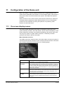
11
Configuration of the Dome unit
Most of the Solaris™ Dome's advanced functions are configured using a menu
system that is presented by the camera's on-screen display (OSD). This section of
the manual covers the use of the OSD menu system, and explains the options it
provides.
When the Dome is new or after a factory reset has been performed, a default tour
is already stored comprising of sixteen preset positions (1 to 16). These preset
positions can be overwritten by storing new positions or by selecting ‘Clear
Presets’ from the Reset menu.
11.1
On-screen display menus
The menus system presented by the OSD is controlled by using keys on the
system telemetry controller. Since the Solaris™ Dome can be controlled by a wide
range of telemetry controllers, the position and labelling of the specific keys used
may vary from system to system. Refer to Section 12: Telemetry controller
operation and setup for specific information.
Menu flowcharts overview
The OSD's main menu contains 8 items, all of which lead to a sub-menu system of
commands when selected. Details of each of these sub-menus and the commands
they contain are presented as flowcharts on the following pages.
CAMERA
This menu provides access to several of the camera's advanced functions.
See Section 11.1.2: The Camera menu for details.
PRESETS TOURS
PATTERNS
This menu is used to set up stationary preset positions, pre-programmed
tours of specific presets, and to record any of the four patterns - a series of
manual movements that can be recorded and then replayed as an alternative
to a tour. It is also used to assign actions to presets; such as recalling tours
and to assign presets to alarms. See Section 11.1.3: The Presets, Tours and
Patterns menu for details
PRIVACY ZONES
This section of the menu system will allow you to set up Privacy Zones.
These are pre-defined sections of the cameras field of view that are blanked
to provide privacy for occupants of the areas covered. See Section 11.1.4:
The Privacy Zones menu for details
SOFT LIMITS AND
SECTORS
Soft Limits will allow you to set up and remove software limits that restrict the
vertical travel of the camera. Sectors will allow individual identification, by
name, of the 16 sectors available within the Solaris™ Dome’s horizontal
movement.
43
Siemens Building Technologies
Fire Safety & Security Products
08.2006
ALARMS
The Solaris™ Dome's XTU is provided with a tamper alarm and seven
general-purpose alarm inputs. This menu is used to set up these alarm
inputs and control the Solaris™ Dome's response when they are triggered.
See Section 11.1.6: The Alarm menu for details.
OSD
This menu will allow you to set up how the OSD will appear to the Solaris™
Dome camera's operator during normal operation. It will allow you to set a
unique name for the camera and then control the information that will appear
on the screen when the camera is viewed. See Section 11.1.7: The OSD
menu for details.
DIAGNOSTICS
This menu provides diagnostic information about the Solaris™ Dome's
operation. See Section 11.1.8: The Diagnostics menu for details.
PASSCODES
This menu will allow you to set up the Operator and Installer level pass
codes for the Solaris™ Dome. See the following section for details.
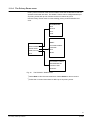
11.1.1 The Passcodes menu
In addition to the telemetry controller pass code or physical key lock you may need
to enter to access the OSD menus, it is possible to set two additional levels of
access pass code for the Solaris™ Dome itself.
These are known as the Operator code and the Installer code, and they provide
different levels of access to the menu items. The Installer code is required to
access the more technical aspects of the configuration.
If these codes have not been set (i.e. left at 0000), no action is required to enter
the menus. If they have been set, you will be prompted to enter an appropriate
code to access the menus that they protect.
Use the Passcodes menu to set up new pass codes, or edit existing ones. Failure
to enter a pass code correctly within three attempts will result in a lock out period of
twenty minutes.
CHANGE INSTALLER CODE
[*]
[*]
PASSCODE MENU
[*]
CHANGE OPERATOR CODE
[*]
CHANGE INSTALLER CODE
STORE
HELP
BACK
CHANGE OPERATOR CODE
ENTER NEW PASSCODE
[*]
[*]
[*]
[*]
STORE
Fig. 20
The PASSCODES menu
44
Siemens Building Technologies
Fire Safety & Security Products
08.2006
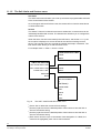
11.1.2
The Camera menu
The camera menu provides control of a number of advanced features of the
camera, and access to settings that affect the camera's response to unusual
lighting conditions.
White Balance
The White Balance menu item controls how the camera adjusts its colour output
under different types of light source. You can choose between two pre-set
configurations (indoor, outdoor), automatic mode, auto tracing mode, one push
mode that can be automatically re-adjusted only at the request of the user and
manual mode where red and blue gain can be adjusted separately by the user.
NOTE
When in One Push mode, use Iris Open to perform a one push.
Backlight
This setting provides backlight compensation for situations where the
background is more brightly lit than the subject
Exposure
The EXP Priority setting determines which aspect of control has priority for the
camera’s automatic exposure setting. Choosing a mode other than auto will
allow you adjust the operation of that mode. The Slow Shutter setting controls
whether slow shutter operation will switch in automatically before the Night time
mode is activated.
NOTE
Automatic Slow Shutter is only available when the exposure
priority is set to Full Auto.
Special menu
Digital zoom
When digital zoom is tuned ON and the maximum optical zoom range is
reached, digital zoom enlarges the centre of the subject by expanding the image
in both the horizontal and vertical directions.
Day/Night mode
The IR-cut filter can be set to engage and disengage automatically as light
levels change, or manually when the Lamps key is pressed.
Auto Flip
The Auto Flip function allows continuous tracking of a target moving under the
Dome without the need for the operator to release the joystick.
Video gain
If very long coax cable runs are used, video degradation is possible, and
particularly noticeable as loss of sharp edges. See Video gain > XTU video
gain in Section 10.3: The XTU main menu for details.
RTU gain
When an RTU (Remote Termination Unit) is in use this setting allows additional
gain to be set to compensate for Cat5 cable lengths in excess of 150 m.
Reset menu
This is also accessible from within the Special menu:
CAMERA MODULE RESET Will reset all camera settings
CLEAR PRESETS
Clears all preset positions and text.
CAMERA RESET
Will re-calibrate the pan & tilt
functions.
FULL FACTORY RESET
Will reset the Dome to factory
settings.
LENS INITIALISE
Allows automatic recalibration of the
lens.
Backup Dome unit All the Dome settings such as camera setup, presets, tours, patterns, privacy
zones and text can be backed up to the XTU and restored at a later date if the
Dome is switched with another or replaced.
45
Siemens Building Technologies
Fire Safety & Security Products
08.2006
AUTO/MANUAL/
ATW/ONE PUSH/²
OUTDOOR/
INDOOR
BRIGHTNESS
SHARPNESS
OFF/ON/KEYBOARD
*VIDEO GAIN*
DONE
VIDEO GAIN
RESET TO DEFAULTS
RTU GAIN
BACK
CAMERA MENU
WHITE BALANCE
CHROMA RED¹
CHROMA BLUE¹
BACKLIGHT
SPECIAL
EXPOSURE
BACK
SPECIAL MENU
*RTU GAIN*
DIGITAL ZOOM .... ON/OFF
RTU GAIN OFF/ON
DAY NIGHT MODE .... AUTO/MANUAL
BACK
AUTOFOCUS KEYBOARD/ON/OFF
CAMERA MODULE RESET
VIDEO GAIN
CLEAR PRESETS
RTU GAIN .... ON/OFF
CAMERA RESET
RESET MENU
FULL FACTORY RESET
BACKUP HU
LENS INITIALISE
HELP
HELP
BACK
BACK
EXPOSURE MENU
EXP PRIORITY .... FULL AUTO/IRIS/
SHUTTER/MANUAL/
KEYBOARD
BACKUP HU DATA TO XTU
RESTORE HU DATA FROM
XTU
SHUTTER SPEED³
IRIS
GAIN
SLOW SHUTTER ................ AUTO/OFF
BACK
Fig. 21
The Camera menu
1
) Use “Chroma Red” and “Chroma Blue” to manually adjust the camera’s white
balance. These settings are only available when the WB “Manual” setting is
selected. Follow the onscreen instructions to adjust them.
2
) ATW = Auto Tracing White balance
use this setting when the type of light source is constantly varying.
3
) The Shutter Speed, Iris and Gain settings are only available, when certain EXP
Priority settings are selected. When KEYBOARD is selected, Iris can be
manually controlled using the Iris keys on the VK3-keyboard. Turning ON Auto
Iris on the keyboard will switch to automatic mode.
46
Siemens Building Technologies
Fire Safety & Security Products
08.2006
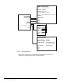
11.1.3 The Presets, Tours and Patterns menu
A Preset is a stored, fixed camera position that you can return to by entering a
preset number on the controller keyboard. The Solaris™ Dome can store up to 99
presets.
A Preset Tour is a pre-configured sequence of presets that the Solaris™ Dome
will move between continuously. The Solaris™ Dome can store up to 4 tours of 32
steps each. Each step can have an associated speed and dwell time.
A Pattern is a recorded sequence of Solaris™ Dome movements that can be
played back repeatedly. The Solaris™ Dome can store four patterns, the length of
which can be up to several minutes.
Presets
Use this item to review, edit, name and store presets. You can also store
preset text, it will remain on the OSD until you move to another pan, tilt or
zoom location.
Preset Tours
This menu item is used to recall and edit preset tours.
Patterns
Use this menu to recall a previously recorded pattern or record a new one.
Inactivity Return
This menu allows you to select an operation that will start after a predefined
period of keyboard inactivity.
Assign Presets
This menu will allow you to assign any of the four tours or the pattern to a
preset. This means that they can be started by recalling the preset.
Within the assign preset menu, it is also possible to assign presets to alarms
that can be recalled when an alarm is triggered.
Two sub-menus will allow you to assign a preset to any of the 8 alarms
NOTE
A random tour is a tour that consists of the steps used in tour 1, but are replayed in a random order.
This helps prevent potential criminals from studying and learning the movement of a traditional tour.
47
Siemens Building Technologies
Fire Safety & Security Products
08.2006
PRESETS
PRESET NUMBER.... (01-99)
STORED ..... (YES/NO/ASSIGNED)1
(enter Preset Name)
STORE PRESET
DELETE PRESET
CLEAR NAME
COPY
PASTE
BACK
PRESET TOURS
RECALL TOUR 1
EDIT TOUR
RECALL TOUR 2
TOUR........ (Select Tour No.)
RECALL TOUR 3
STEP ........ (Select Step No.)
RECALL TOUR 4
PRESET..... 1-99 (Select Preset No.
EDIT TOUR 1
O = Skip step).
EDIT TOUR 2
SPEED ...... 0-100
EDIT TOUR 3
DWELL...... 0-255 seconds
EDIT TOUR 4
BACK
BACK
RECALL PATTERN
PATTERN MENU
RECALL PATTERN 1
RECALL A PATTERN
RECALL PATTERN 2
RECORD A PATTERN
PRESET MENU
DELETE PATTERN 1
PRESETS
DELETE PATTERN 2
PRESET TOURS
DELETE PATTERN 3
PATTERNS
DELETE PATTERN 4
INACTIVITY RETURN
HELP
ASSIGN PRESETS
BACK
RECALL PATTERN 3
RECALL PATTERN 4
RECORD PATTERN
RECORD PATTERN 1
RECORD PATTERN 2
RECORD PATTERN 3
BACK
RECORD PATTERN 4
INACTIVITY RETURN
ACTION.....OFF/HOME/TOUR1-4/
PATTERN1-4/
RANDOM
*ASSIGN TOURS*
TOUR1
TOUR2
TIME PERIOD... 1,5,10,15,
30 MINUTES
HELP
TOUR3
TOUR4
RONDOM
BACK
*ASSIGN PRESETS*
TOURS
*ASSIGN PATTERNS*
PATTERNS
PATTERN1
ALARM PRESETS
PATTERN2
HELP
PATTERN3
BACK
PATTERN4
BACK
ASSIGN ALARM PRESETS²
TAMPER ALARM... (Set 1-99)
ALARM 1 ...(Set 1-99)
1
Setting is read only, not editable
2
‘O’ means no preset assigned
to Alarm.
)
)
Fig. 22
ALARM 2 ...(Set 1-99)
ALARM 3....(Set 1-99)
ALARM 4-7
ALARMS 4-7²
ALARM 4 .. (Set 1-99)
ALARM 5 .. (Set 1-99)
ALARM 6... (Set 1-99)
ALARM 7 ... (Set 1-99)
The PRESETS, TOURS and PATTERNS menu
48
Siemens Building Technologies
Fire Safety & Security Products
08.2006
11.1.4 The Privacy Zones menu
Privacy zones are areas of the camera’s field of view that are blanked so that the
operator cannot see into them. The Solaris™ Dome can be configured with up to
24 privacy zones and up to 8 of these can be on screen at any time.
Use the Privacy Zones menu to review existing privacy zones and define new
ones.
REVIEW ZONES¹
NEXT
DELETE
HELP
BACK
PRIVACY ZONES
REVIEW ZONES
DEFINE ZONE
ZONE COLOUR
BACK
STEP1²
POSITION CAMERA
CONTINUE
HELP
ABORT
BLACK/GREY1-GREY7/
RED/GREEN/BLUE/
CYAN/YELLOW/
MAGENTA
Fig. 23
The PRIVACY ZONES menu
1
) Select Next to view the next stored zone. Select Delete to remove a zone.
2
) Follow the on-screen instructions to define up to 24 privacy zones.
49
Siemens Building Technologies
Fire Safety & Security Products
08.2006
11.1.5
The Soft Limits and Sectors menu
Soft limits
The Soft Limits menu will allow you to set up and remove programmable soft limits
to the vertical travel of the camera.
Once the upper and lower limits are set, the camera will not view the areas above
or below those limits.
Sectors
The Solaris™ Dome’s horizontal movement is divided into 16 sectors that can be
individually identified with a name. The Sectors item will allow you to configure the
names of the sectors.
When the sector function is activated (in the OSD menu, see Section 11.1.7), the
sector name is displayed on screen whenever the camera is looking into that
sector. The purpose of this is to provide the operator with help in orientation. The
Edit Sector menu allows you to edit the sector name.
For example: North >> East >> South >> West
STORE UPPER SOFT LIMIT²
STORE
ABORT
LIMITS AND SECTORS
SET UPPER SOFT LIMIT
STORE LOWER SOFT LIMIT³
SET LOWER SOFT LIMIT
STORE
CLEAR SOFT LIMIT1
ABORT
SECTORS
BACK
SECTOR MENU
SECTOR NUMBER...116
(Set Name)4
CLEAR NAME
COPY
PASTE
HELP
BACK
Fig. 24
The SOFT LIMITS AND SECTORS menu
1
) Press ‘Set’ to delete the current soft limit settings.
2
) Use the joystick to tilt to the desired position. Select store to save the limit or
abort to exit without saving.
3
) Use the joystick to tilt to the desired position. Select store to save the limit or
abort to exit without saving.
4
) Each sector can have up to 24 characters of text assigned to it. If blank, the
whole line is highlighted, press ‘Set’ to add characters.
50
Siemens Building Technologies
Fire Safety & Security Products
08.2006
11.1.6
The Alarm menu
The Alarm menu provides access to settings relating to the alarm contacts in the
XTU unit. Each of the 8 alarms can be configured individually to respond in a
different way.
Contact
Selects whether the alarm contacts are normally open(N/O) or normally
closed (N/C).
Video blanking
Video blanking provides a way of signalling an alarm for systems that do not
support remote reporting. When set to Yes, an alarm will blank the video for
3 seconds.
For example: A V2 system with video loss alarms fitted.
Relay
Selecting Momentary will cause the relay output to operate for 3 seconds
when an alarm occurs. Select Latched for the relay to operate for the full
duration of the alarm.
Alarm text
Each alarm can be identified with 24 characters of text that will appear when
an alarm occurs, remaining on-screen until the alarm is acknowledged by a
user manually controlling the Dome
Global settings
Local report
Enables a local response of the alarm. The Dome moves to the assigned
preset position and displays the user entered text (see Assign alarm
presets in Section 11.1.3: The Presets, Tours and Patterns menu).
Remote report
Enables remote reporting of the alarm (for systems with bi-directional
telemetry - the alarm state is signalled to the controller).
Alarm resume
This setting, in conjunction with Time Period, determines what action the
Solaris™ Dome will perform after an alarm has occurred. When Alarm
Resume is set to Home the camera will return to home position (preset
1). Alternatively, you can select any of the four tours or four patterns
(assuming these have been programmed – see Section 11.1.3: The
Presets, Tours and Patterns menu).
Time period
Sets a delay period before performing the action specified in ‘Alarm
resume’
51
Siemens Building Technologies
Fire Safety & Security Products
08.2006
ALARM CONFIGURATION
ALARM ..... (Tamper/1-3/4-7)
ENABLED .. YES/NO
CONTACT .. N/C / N/O
VIDEO BLANKING ... YES/NO
RELAY....... NONE/MOMENTARY/LATCHED
ALARM MENU
TAMPER ALARM
(Set Name)1
CLEAR NAME
ALARM 1
COPY
ALARM 2
PASTE
ALARM 3
BACK
ALARM 4-7
GLOBAL ALARM SETTINGS
BACK
ALARMS 4-7
ALARM 4
ALARM 5
ALARM 6
ALARM 7
BACK
GLOBAL SETTINGS
LOCAL REPORT ..... YES/NO
REMOTE REPORT .. YES/NO
ALARM RESUME.... OFF/HOME/TOUR1-4/
PATTERN1-4/RANDOM
TIME PERIOD ........ 5SECS-30MINS
HELP
BACK
Fig. 25
The ALARM menu
1
) Each alarm can have up to 24 characters of text assigned to it. If blank, the
whole line is highlighted, press "Set" to add characters.
52
Siemens Building Technologies
Fire Safety & Security Products
08.2006
11.1.7 The OSD menu
The OSD menu is used to set up what information is displayed on screen during
routine operation. The display is dynamic, and items such as alarms are only
displayed when they are relevant. New items will overwrite existing items at the
same location in the following order of priority:
1.
Receiver address
2.
Alarm name
3.
Information message
4.
Preset number
5.
Preset name
6.
Sector name
7.
Camera number
8.
Camera name
9.
Status
Camera details
This allows you to set up a name and number for the camera (note that
the camera number is just an identifier for the camera and not the
receiver address).
OSD configuration
This allows you to choose which items to display, and where to locate
them on-screen. The screen is divided into left and right and 12 lines
vertically (1 = top; 12 = bottom).
OSD MENU
SET CAMERA DETAILS
CONFIGURE OSD
BACK
CAMERA DETAILS
RECEIVER ADDRESS1
CAMERA NUMBER...001-999
CAMERA NAME²
CLEAR NAME
HELP
BACK
OSD CONFIGURATION
CAMERA NUMBER...Off/ 1-12 Left / 1-12 Right
CAMERA NAME... Off/1-12 Left / 1-12 Right
PRESET NUMBER...Off/ 1-12 Left / 1-12 Right
PRESET NAME...Off/ 1-12 Left / 1-12 Right
SECTOR NAME... Off/1-12 Left / 1-12
ALARM NAME... Off/1-12 Left / 1-12 Right
STATUS...Off/ 1-12 Left / 1-12 Right
BACK
Fig. 26
The OSD menu
1
) Setting is read only, not editable.
) “CAMERA NAME” can have up to 24 characters of text assigned to it.
If blank, the whole line is highlighted, press ‘Set’ to add characters)
2
53
Siemens Building Technologies
Fire Safety & Security Products
08.2006
11.1.8 The Diagnostics menu
This menu is intended for use by technicians and provides access to various
diagnostic parameters within the Solaris™ Dome.
DIAGNOSTICS 2
DIAGNOSTICS 3
1
PAN POSITION
MAX TEMP
1
TILT POSITION
MIN TEMP
RECEIVER
PAN SPEED
CURRENT TEMP
INITIAL TEST
TILT SPEED
XTU TEMP
MORE
ZOOM POSITION
HEATER
BACK
FOCUS POSITION
DISTANCE KM
MORE
FAN CONDITION
BACK
BACK
DIAGNOSTICS 1
[SW257 1 0]
[SW258 1 0]
CONTACT DETAILS
Fig. 27
The DIAGNOSTICS menu
1
) Setting is read only, not editable.
54
Siemens Building Technologies
Fire Safety & Security Products
08.2006
12
Telemetry controller operation and setup
This chapter explains how to operate the Solaris™ Dome using a telemetry
controller and describes:
z Accessing the OSD (Siemens, Molynx 6000, V3i and 3rd party)
z Protocol tables
12.1
Telemetry keyboard operation
A great deal of the configuration and set up of the Solaris™ Dome must be carried
out using the on-screen menu system that is described in Section 11: Configuration
of the Dome unit.
12.1.1
Access to the OSD with Siemens controllers
CKA4820/CKA3210 series controllers
Ensure that the telemetry control port of the CKA keyboard (Com-Port 2) is set to
“CCDA-protocol”. Use the following keys to navigate the Dome OSD menu:
Key
Function
65 Pos or Cam + F1
Menu On
66 Pos or Cam + F10
Menu Off
Tilt Up
Up
Tilt Down
Down
Pan Left
Left
Pan Right
Right
Focus Far
Select parameter / submenu
Focus Near
Deselect parameter / exit submenu
1 Pos
Toggle between OSD and PTZ navigation (function only available
when opening OSD via “65 Pos”)
NOTE
When opening the OSD with Cam + F1 it is necessary to exit the OSD with Cam + F10. It is possible
to exit the OSD menu by selecting the EXIT option in the OSD main menu. If so, the keyboard will
remain in menu mode (green LED flashing). It is necessary to use Cam + F10 to exit menu mode on
the keyboard in that case. Also Solaris™ will automatically exit the OSD mode after approx. 2 minutes
of no activity. In this case it is as well necessary to use Cam + F10 to exit menu mode on the
keyboard. When opening OSD with Cam + F1, toggling between OSD navigation and PTZ navigation
is not possible.
SIMATRIX NEO and SIMATRIX SYS/648/164 via dome converter CAC0103
Key
Function
65 Pos or button OSD
Menu On
66 Pos
Menu Off
Tilt Up or button UP
Up
Tilt Down or button DOWN
Down
Pan Left
Left
Pan Right
Right
Focus Far or button SET
Select parameter / submenu
Focus Near
Deselect parameter / exit submenu
1 Pos
Toggle between OSD and PTZ navigation
55
Siemens Building Technologies
Fire Safety & Security Products
08.2006
12.1.2
Access to the OSD with Bewator controllers
To gain access to the OSD you will need to enter the telemetry controller's
programming mode.
Bewator 6000 series controller
OSD access on the 6000 series requires the entry of a PIN number, and is
therefore restricted to authorised persons only:
1.
Enter the 6 digit PIN number.
2.
Select "Setup camera" from the menu.
3.
Select the item by pressing the "Play" key.
4.
Use the following keys to navigate the menus:
Key
Function
Menu On/Off
Up
Down
Enter
Left
Right
Bewator v3i controller
1.
Turn the key to enter programming mode.
2.
Press
3.
Select ‘Camera Setup’.
4.
Select the relevant v3i option to navigate the menus.
to move to the 2nd page.
12.1.3 Access to the OSD with 3rd party controllers
1.
Press 95 Preset Recall.
OR
Preset 2 Recall, Preset 2 Recall (within 2 seconds of each other).
NOTE
Both special presets for accessing the menu can be changed or disabled using the XTU. See Section
10.3: The XTU main menu for details.
2.
Navigate the menus using the joystick.
3.
To select use Preset 3 Recall.
NOTE
Use Preset 1 to toggle between Pan / Tilt (camera operation) and OSD menu navigation.
56
Siemens Building Technologies
Fire Safety & Security Products
08.2006
12.2
Advanced camera functions
The 6000 series and v3i controllers also provide direct access to advanced camera
functions:
Lens slow
This function slows down the operation of the lens's Zoom and Focus functions to
make it easier to control when fine adjustments are necessary. The function
toggles on and off.
Lamps
If set to Manual in the camera special menu, this function toggles between the
camera's day and night setting.
Autofocus
The Autofocus function can be toggled on and off. The manual focus keys can still
be used when autofocus is latched on, but the Solaris™ Dome will start to
autofocus again after a pan, tilt or zoom operation.
Auto Iris
When the EXP priority is set to Keyboard, the Iris can be manually controlled using
the Iris Open and Iris Close keys on the keyboard, or switched to Automatic Iris by
pressing the Auto Iris key.
Function
6000 series
v3i
Lens Slow
Lamps
Enter the camera function control and select the
relevant v3i option to navigate the menus.
Autofocus
Auto Iris
12.3
Use with Siemens controllers
The Siemens CCDA protocol is implemented and may be selected from the
protocol menu. Controlling the dome using the CCDA protocol can be performed
by direct connected keyboard CKA48xx/CKA32xx, SIMATRIX Neo (Port 1) and
SIMATRIX SYS / 648 / 164 by using the dome converter CAC0103, Release V1.7
(Aug. 06).
57
Siemens Building Technologies
Fire Safety & Security Products
08.2006
12.3.1 Direct control via CKA48xx/CKA32xx
NOTE
We recommend following interfacing:
z RS485 connection, 9600 baud, even parity, 8 data bits, 1 stop bit
z Camera addressing is 0-127
Tested using Siemens keyboard CKA4820
Operation
User
keyboard
action
Pan Left (variable speed)
Pan Left
Pan Right (variable speed)
Pan Right
Tilt Up (variable speed)
Tilt Up
Tilt Down (variable speed)
Tilt Down
Focus Near
Focus Near
Focus Far
Focus Far
Zoom In
Zoom In
Zoom Out
Zoom Out
All Stop
Cam + Stop
OSD Setup On
Cam + F1
Notes
Also available by Pos 65. When opening the OSD with “Cam” + F1 it is necessary to exit
the OSD with “Cam” + F10. It is possible to exit the OSD menu by selecting the EXIT
option in the OSD main menu. If so, the keyboard will remain in menu mode (green LED
flashing). It is necessary to use “Cam” + F10 to exit menu mode on the keyboard in that
case. Also Solaris™ will automatically exit the OSD mode after approx. 2 minutes of no
activitiy. In this case it is necessary to use “Cam” + F10 to exit menu mode on keyboard.
AutoFocus On
Cam + F2
Flip
Cam + F3
Toggle Colour / B&W
Cam + F4
This function will toggle the automatic D/N function if preset.
Pattern Record
Cam + F6
Enters pattern record mode for pattern 1 (direct).
Pattern Stop
Cam + F7
Ends pattern record mode for pattern 1 (direct).
Pattern Save
Cam + F8
Ends pattern record mode pattern 1 and saves (direct).
Pattern Test
Cam + F9
Recalls the last pattern recorded (direct).
Exit OSD menu
Cam + F10
Store Preset 1-64
[1…64] Mem
Recall Preset 1-64
[1…64] Pos
Enter OSD menu
65 Pos
Also available using Cam+F1.
Exit OSD
66 Pos
Also available using Cam+F10.
Go to Home position
67 Pos
Home is Preset 1 on Solaris™.
Flip
68 Pos
Start Auto Patrol
69 Pos
BLC On
70 Pos
BLC Off
71 Pos
One Push White Balance
72 Pos
One Push AutoFocus
73 Pos
Display Version
74 Pos
Setup privacy zone
76 Mem
IR Cut Filter On ("Night
Mode")
77 Pos
Starts preset tour.
Displays Dome and XTU firmware versions.
IR Cut Filter Off ("Day Mode")
78 Pos
Stop Scan
83 Pos
Stops current sequence / tour / pattern.
Random Scan
84 Pos
Starts random preset tour.
Frame Scan
85 Pos
Starts preset sequence (fixed speed, uniform dwell time).
Auto Scan
86 Pos
Starts preset tour.
Record / Recall Pattern 1
87 Mem / Pos Starts recording or playing Pattern 1.
58
Siemens Building Technologies
Fire Safety & Security Products
08.2006
Record / Recall Pattern 2
88 Mem / Pos Starts recording or playing Pattern 2.
Record / Recall Pattern 3
89 Mem / Pos Starts recording or playing Pattern 3.
Record / Recall Pattern 4
90 Mem / Pos Starts recording or playing Pattern 4.
Stop Pattern Record
91 Pos
Stops recording current pattern.
12.3.2 Control via SIMATRIX NEO and dome converter CAC0103
The Siemens Solaris™ Dome can be controlled via the SIMATRIX video matrices.
SIMATRIX NEO provides direct physical connection via telemetry port 1. For
connection with SIMATRIX SYS / 648 / 164 an additional dome converter
CAC0103, Release V1.7 (Aug. 06) is required to interface the RS485 port of the
dome to the TTY port of the video matrix and to perform the necessary code
translation.
NOTE
We recommend following interfacing:
z RS485 connection, 9600 baud, even parity, 8 data bits, 1 stop bit,
z camera addressing is 0-254.
Tested using Siemens keyboard CKA4820 and SIMATRIX NEO , CAC0103
Operation
User keyboard action
Pan Left (var. speed)
Pan Left
Pan Right (var. speed)
Pan Right
Tilt Up (var. speed)
Tilt Up
Tilt Down (var. speed)
Tilt Down
Focus Near
Focus Near
Focus Far
Focus Far
Zoom In
Zoom In
Zoom Out
Zoom Out
Store Preset 1-64
[1…64] Mem
Recall Preset 1-64
[1…64] Pos
Enter OSD menu
65 Pos
Exit OSD
66 Pos
Go to Home Position
67 Pos
Flip
68 Pos
Start Auto Patrol
69 Pos
BLC On
70 Pos
BLC Off
71 Pos
One Push White Balance
72 Pos
One Push AutoFocus
73 Pos
Display Version
74 Pos
Setup privacy zone
76 Mem
IR CutFilter On ("Night Mode")
77 Pos
Notes
Home position is Preset 1 on Solaris™.
Start Preset Tour.
Displays Dome and XTU firmware versions.
IR Cut Filter Off ("Day Mode")
78 Pos
Stop Scan
83 Pos
Stops current sequence / tour / pattern.
Random Scan
84 Pos
Starts random preset tour.
Frame Scan
85 Pos
Starts preset sequence (fixed speed, uniform dwell time).
Auto Scan
86 Pos
Starts preset tour.
Record / Recall Pattern 1
87 Mem / Pos
Starts recording or playing Pattern 1.
Record / Recall Pattern 2
88 Mem / Pos
Starts recording or playing Pattern 2.
Record / Recall Pattern 3
89 Mem / Pos
Starts recording or playing Pattern 3.
Record / Recall Pattern 4
90 Mem / Pos
Starts recording or playing Pattern 4.
Stop Pattern Record
91 Pos
Stops recording current pattern.
59
Siemens Building Technologies
Fire Safety & Security Products
08.2006
12.4
Use with Bewator controllers
The following Bewator (Molynx) protocols are implemented and may be selected
from the PROTOCOL menu:
z Molynx
z Molynx V3
z PCCON
z PCCON 1-Way
12.4.1
Molynx & Molynx V3
NOTE
We recommend following interfacing:
z RS485 connection; 9600 baud, even parity, 8 data bits, 1 stop bit.
z Camera addressing is 0-511 for cameras 1-512. Also responds to broadcast addresses.
Tested using Bewator 600-Series, 6000-Series, Visilynx 2, Visilynx 2+, Visilynx V3i.
Operation
User action
Notes
Pan / Tilt / Zoom / Focus
Joystick for pan/tilt;[ZOOM IN] / [ZOOM
OUT] for zoom; [FOCUS NEAR] /
[FOCUS FAR] for focus
When in OSD cursor mode Pan / Tilt operate as cursor right /
left / up / down (but see also Recall Preset 1 below).NB: on a
Visilynx 2 when in the CAMERA SETUP menu on the
keyboard it is not possible to control the camera's pan/tilt; it is
necessary to exit this keyboard menu to do so.
Iris
[IRIS OPEN] / [IRIS CLOSE]
Only operates when exposure priority is set to KEYBOARD.
AutoIris
[AUTOIRIS]
Overrides manual iris operation
AutoFocus Off / On
[AUTOFOCUS ]
Toggle action. Not available on 600-Series keyboard.
Day Mode / Night Mode
[LAMPS]
Toggle action. Switches camera between day and night
modes (colour/mono version only).
One-Touch White Balance
[IRIS OPEN]
If one-touch white balance is enabled in OSD and exposure
priority is not set to KEYBOARD.
Recall Preset
[n] [PRESET RECALL]
Range 1-99. Preset 95* or Preset 2* twice within 2 seconds
functions as the OSD Mode 'MENU' command. When in OSD
mode Preset 1 switches the joystick between cursor and
camera control. When in OSD cursor mode Preset 3 functions
as SET.
Store Preset
[n] [PRESET PROGRAM] or [PROGRAM
KEY] [n] [PRESET] depending on
controller
Range 1-99.
Run Preset Sequence
[PRESET SEQUENCE]
Not available on 6000-Series keyboard.
Program Preset Sequence
Save from sequence edit mode on
keyboard.
Action varies depending on keyboard.
Run Preset Tour
[PRESET TOUR]
Not available on 600-Series keyboard.
Program Preset Tour
Save from tour edit mode on keyboard.
Action varies depending on keyboard. Preset list for tour is the
same as that for the preset sequence.
Run Pattern
[n] [PRESET TOUR]
n can be 1, 2 or 3. Not available on 6000-Series keyboard.
Operate Relay
[AUX1]
Toggle action. Not available if any alarms are programmed to
operate the relay.
Enter OSD menu mode
[MENU] On a 6000-Series keyboard the
[GLOBAL ON] key is used.
Recall Preset 95* or Recall Preset 2* twice within 2 s also
operates as the Menu function.
OSD menu navigation
[SET], [UP], [DOWN], [LEFT], [RIGHT].
On a 6000-Series keyboard the keys are:
If OSD menu mode was entered using Recall Preset 95*
(or Recall Preset 2* twice within 2 s) Recall Preset 3 will also
operate as the Set function and the joystick will operate as
Up, Down, Left and Right (the joystick can be switched
between cursor movement and camera control by Recall
Preset 1).
[GLOBAL OFF]
[PAUSE]
[MULTISCREEN]
[REWIND]
[FAST FWD]
*) The presets used to access the OSD are programmable via the XTU
60
Siemens Building Technologies
Fire Safety & Security Products
08.2006
Alarms
When using Molynx V3 protocol in conjunction with a V3i telemetry matrix it is
possible to send alarms back over the telemetry link. It is necessary to configure
the V3i to have bi-directional telemetry on the channel being used and for the
appropriate camera alarms to be enabled. Also, on the Solaris™, the alarms must
be configured to have Remote Reporting enabled.
Only the tamper and alarms 1-6 may be sent back, alarm 7 is not usable in this
way. The mapping is such that the tamper is the first alarm in the block of 8 camera
alarms, followed by alarms 1-6.
With a controller other than a V3i it is not possible to use bi-directional telemetry
hence remote reporting of alarms is not available. Use normal Molynx - not Molynx
V3 - telemetry in these instances.
12.4.2 PCCON, PCCON 1-way and PCCON MULTIDROP
NOTE
RS485 connection; 9600 baud, even parity, 8 data bits, 1 stop bit.
Tested using a PC running Hyperterminal with direct connection to serial port
Operation
User command
Notes
Return Status
@1
Returns camera number and latched functions status.
Select Camera
@3, n
(Multidrop only)
Selects camera n as the current camera, disabling all others.
Camera Function On
@5, n
Home (n=1), Pan Right (2), Pan Left (3), Tilt Up (4), Tilt Down (5),
Zoom In (6), Zoom Out (7), Focus Far (8), Focus Near (9), Iris Close
[10], iris Open [11], AutoIris [20], LensSlow (22), AutoFocus (23) are
implemented. Also Lamps (21) switches the unit from day to night
mode (colour/mono version only).When in OSD mode (and only
after OSD mode is accessed using a preset as detailed below)
Pan/Tilt commands from the controller are sent as Camera Setup
commands RIGHT/LEFT/UP/DOWN (but see also Recall Preset 1
below).
Camera Function Off
@6, n
Pan Right (n=2), Pan Left (3), Tilt Up (4), Tilt Down (5), Zoom In (6),
Zoom Out (7), Focus Far (8), Focus Near (9), LensSlow (22),
AutoFocus (23) are implemented. Also Lamps (21) switches the unit
from night to day mode (colour/mono version only).When in OSD
mode (and only after OSD mode is accessed using a preset as
detailed under Recall Preset below) Pan/Tilt commands from the
controller are sent as Camera Setup commands
RIGHT/LEFT/UP/DOWN (but see also Recall Preset 1 below).
P/T Speed
@7, p, t
0 to 100% for each.
Recall Preset
@8, n
Range 1-99 (not 95). Recall Preset 95* or Recall Preset 2* twice
within 2 seconds sends the Camera Setup Mode 'MENU' command.
When in OSD mode Recall Preset 1 toggles between sending
Pan/Tilt commands as PAN/TILT and sending them as CURSOR
RIGHT/LEFT/UP/DOWN. When in OSD mode Recall Preset 3
sends the SET command.
Program Preset
@9, n
Range 1-99.
Preset Sequence Recall
@10
Preset Sequence Program
@11, n, p1 … pn, d
Preset Tour Recall
@12
Preset Tour Program
@13, s1, …, s16, d1, …, d16
Programs tour speeds and dwells (16 of each). Presets are the
same as those programmed with the Preset Sequence Program
command. Values are ignored for unused positions.
Variable Speed Preset Recall
@16, p, s
Preset range 1-99; speed range 1-100%.
Relay Status
@26, 1
Return relay status (must be relay 1). 0=open, 1=closed
Relay Control
@27,1,f
Operate relay (f=0 to turn off, f=1 to turn off). Must be relay 1.
2-16 (n) positions. Sets sequence/tour positions (p1…pn) (range 199) and dwell time (d) (range 1-255s).
61
Siemens Building Technologies
Fire Safety & Security Products
08.2006
Operation
User command
Notes
Return Preset Sequence
Information
@39
Returns preset sequence last downloaded to the XTU. Note that this
data is the last which was sent to the XTU and, for example if the
sequence was subsequently re-programmed using the OSD, it may
not be the same as the sequence stored in the Dome unit.
Return Preset Tour Information
@40
Returns preset tour last downloaded to the XTU. Note that this data
is the last which was sent to the XTU and, for example if the tour
was subsequently re-programmed using the OSD, it may not be the
same as the sequence stored in the Dome unit.
Camera Function All On
@41, n
Supports Lamps (n=6), LensSlow (7), AutoFocus (8).
Camera Function All Off
@42, n
Supports Lamps (n=6), LensSlow (7), AutoFocus (8).
Camera Setup (OSD menu
command)
@47, n
Sends the OSD menu command for Set (n=0), Up (1), Down (2),
Right (3), Left (4), Menu (5).
Return Software Version
@55
Returns XTU software version number (major and minor numbers).
*) The presets used to access the OSD are programmable via the XTU.
The following responses are implemented
OK
Command actioned correctly
ER
Syntax error or parameter error
NC
No control permitted
NI
Command not implemented
CS
Checksum error
Some commands return more information as detailed in the PCCON specification.
These are @1, @26, @39, @40 and @55. In addition, if a checksum is sent with
the command it will be returned in the response. (See the full PCCON3
specification for details).
If the protocol is set to 'PCCON 1-Way' no responses will be returned under any
circumstances.
If the protocol is set to PCCON multidrop, @3 must be used to select the required
camera before any commands will be processed.
62
Siemens Building Technologies
Fire Safety & Security Products
08.2006
12.5
Use with 3rd party controllers
It is possible to configure the Solaris™ Dome to be controlled via RS485 using a
number of other manufacturer's controllers. When using a controller other than
those offered by Siemens or Bewator (incorporating Molynx technology); there may
be variations in the actions a user must take in order to perform a particular task.
Where there is a lack of consistency between controllers, the Solaris™ Dome will
attempt to overcome these problems. It is therefore necessary on occasion to use
buttons on a controller to perform a different operation to that which may be
explained in the controllers manual. This is sometimes required to fully utilise the
functionality of the Solaris™ Dome.
The following third party protocols are implemented and may be selected from the
PROTOCOL menu:
z Pelco D
z Pelco P
z Ernitec ERNA
z VCL
z Vicon
z Videmech Universal
z Philips
z Photon
z TTY
NOTE
TTY mode is used for communication with a PC for firmware upgrades and should not be selected in
normal use.
Details for the functions supported in these protocols are listed below.
12.5.1 Pelco P & D protocols
NOTE
Pelco P
RS485 connection; 2400 or 4800 baud selectable, no parity, 8 data bits, 1 stop bit. Camera
addressing is 0-31 for cameras 1-32.
Pelco D
RS485 connection; 2400 baud, no parity, 8 data bits, 1 stop bit. Camera addressing is 1-255 for
cameras 1-255.
Tested using PELCO Universal Keyboard KBD300 + CM6700 Matrix.
Operation
User action
Notes
Pan / Tilt /Zoom / Focus
Joystick for pan/tilt/zoom,
[NEAR] / [FAR] for focus
When in OSD cursor mode Pan / Tilt operate as cursor right / left /
up / down (but see also Recall Preset 1 below).
Iris
[OPEN] / [CLOSE]
Only operates when exposure priority is set to KEYBOARD.
AutoFocus On
[1] [F4]
Activates Auxiliary 1 function.
AutoFocus Off
[1] [F5]
Deactivates Auxiliary 1 function.
Night Mode
[4] [F4]
Activates Auxiliary 4 function. Switches camera to night mode
(colour/mono version only).
Day Mode
[4] [F5]
Deactivates Auxiliary 4 function. Switches camera to day mode
(colour/mono version only).
One-Touch White Balance
[OPEN]
If one-touch white balance is enabled in OSD and exposure priority
63
Siemens Building Technologies
Fire Safety & Security Products
08.2006
Operation
User action
Notes
is not set to KEYBOARD.
Recall Preset
[n] [PRESET]
Range 1-89.Preset 95* or Preset 2* twice within 2 seconds functions
as the OSD Mode 'MENU' command. When in OSD mode Preset 1
switches the joystick between cursor and camera control. When in
OSD cursor mode Preset 3 operates as SET.
Store Preset
[n] hold [PRESET]
Range 1-89.
Run Pattern
[PATTERN]
Enter OSD Menu Mode
[9] [5] [PRESET] or [2]
[PRESET] [2] [PRESET] within
2 seconds.
Recall Preset 95* or Recall Preset 2* twice within 2 seconds
functions as the OSD Mode 'MENU' command.
Navigate OSD Menu Mode
Joystick for
Up/Down/Left/Right.[3]
[PRESET] for Set.
When in OSD mode Recall Preset 1 switches the joystick between
cursor and camera control. When in OSD cursor mode Recall
Preset 3 operates as SET
* The presets used to access the OSD are programmable via the XTU.
12.5.2 Ernitec ERNA protocol
NOTE
RS485 connection; 2400 baud, no parity, 8 data bits, 1 stop bit.
Camera addressing is 0-254 for cameras 1-255. Also responds to broadcast address 255.
Tested using Ernitec Keyboard 1503M.
Operation
User action
Notes
Pan / Tilt /Zoom / Focus
Joystick for Pan/Tilt/Zoom,[FN] / [FF]
for Focus
When in OSD cursor mode Pan / Tilt operate as cursor right / left /
up / down (but see also Recall Preset 1 below).
Iris
[OPEN] / [CLOSE]
Only operates when exposure priority is set to KEYBOARD.
AutoIris On
[AUTO] [OPEN] or [AUTO] [CLOSE]
Overridden automatically on a manual iris operation.
AutoFocus On
[AUTO] then either [FN] or [FF]
AutoFocus Off
[FN] or [FF]
Manual control overrides autofocus.
Night Mode
[4] [AUX ON]
Activates Auxiliary 4 function. Switches camera to night mode
(colour/mono version only).
Day Mode
[4] [AUX OFF]
Deactivates Auxiliary 4 function. Switches camera to day mode
(colour/mono version only).
One-Touch White Balance
[IC]
If one-touch white balance is enabled in OSD and exposure priority
is not set to KEYBOARD.
Recall Preset
[n] [PRESET]
Range 1-99. Preset 95* or Preset 2* twice within 2 seconds
functions as the OSD Mode 'MENU' command. When in OSD mode
Preset 1 switches the joystick between cursor and camera control.
When in OSD cursor mode Preset 3 operates as SET.
Start Preset Sequence
[PRESET SEQUENCE]
Starts Tour 1.
Save Preset
[n] [ESC] [PRESET]
Range 1-99.
Insert Preset into Stack
[n] [SHIFT]+[INS]
Appends specified preset to end of current tour if possible**. Speed
= 100%, Dwell = currently selected dwell.
Delete Preset from Stack
[n][SHIFT]+[DEL]
Deletes the last occurrence of the specified preset from the tour** (if
present) and moves the presets above it down by one position.
Leaves any other occurrences of the same preset in the tour intact.
Clear Stack
[ESC] [AUX OFF]
Clears the tour**.
Sequence Dwell Time
[n] [TIME]
Sets the dwell time used by the next Insert Preset into Stack
command*.
Enter OSD Menu Mode
[9] [5] [PRESET] or[2] [PRESET] [2]
[PRESET] within 2 seconds
Recall Preset 95* or Recall Preset 2* twice within 2 seconds
functions as the OSD Mode 'MENU' command.
Navigate OSD Menu Mode
Joystick for Up/Down/Left/Right.[3]
[PRESET] for Set.
When in OSD mode Recall Preset 1 switches the joystick between
cursor and camera control. When in OSD cursor mode Recall
Preset 3 operates as SET.
* The presets used to access the OSD are programmable via the XTU.
** It is recommended that the OSD is used to setup a Tour.
64
Siemens Building Technologies
Fire Safety & Security Products
08.2006
12.5.3 VCL protocol
NOTE
RS485 connection; 9600 baud, no parity, 8 data bits, 2 stop bits.
Camera addressing is 0-127 for cameras 1-128.
Tested using Honeywell HKJMSTP-00 keyboard and HMAX081-00 matrix.
Operation
User action
Notes
Pan / Tilt /Zoom / Focus
Joystick for Pan/Tilt/Zoom,[FN] / [FF]
for Focus
When in OSD cursor mode Pan / Tilt operate as cursor right / left /
up / down (but see also Recall Preset 1 below).
Iris
[IRIS+] / [IRIS -]
Only operates when exposure priority is set to KEYBOARD.
AutoIris On
[AUTOIRIS]
Overridden automatically on a manual iris operation.
AutoFocus On
[FOCUS AUTO]
AutoFocus Off
[FN] or [FF]
Manual control overrides autofocus.
Day Mode / Night Mode
[AUX]
Toggle action. Switches camera between day and night modes
(colour/mono version only). It is not possible to indicate the current
state on the keyboard.
One-Touch White Balance
[IRIS -]
If one-touch white balance is enabled in OSD and exposure priority
is not set to KEYBOARD.
Recall Preset
[n] [PRESET] or use one of [PRESET
1], [PRESET 2], [PRESET 3],
[PRESET 4]
Range 1-99.Preset 95* or Preset 2* twice within 2 seconds functions
as the OSD Mode 'MENU' command. When in OSD mode Preset 1
switches the joystick between cursor and camera control. When in
OSD cursor mode Preset 3 operates as SET.
Start Preset Tour
[1] [AUTOPAN]
Starts Tour 1.
Save Preset
hold [PRESET], press [n], release
[PRESET]
Range 1-99.
Enter OSD Menu Mode
[9] [5] [PRESET] or [PRESET 2]
[PRESET 2] within 2 seconds
Recall Preset 95* or Recall Preset 2* twice within 2 seconds
functions as the OSD Mode 'MENU' command.
Navigate OSD Menu Mode
Joystick for Up/Down/Left/Right.
[PRESET 3] for Set.
When in OSD mode Recall Preset 1 switches the joystick between
cursor and camera control. When in OSD cursor mode Recall
Preset 3 operates as SET.
* The presets used to access the OSD are programmable via the XTU.
12.5.4
Videmech Universal protocol
NOTE
RS485 connection; 9600 baud, odd parity, 8 data bits, 1 stop bit.
Camera addressing is 1-254 for cameras 1-254. Also responds to broadcast address 255.
Tested using Videmech Vertex keyboard.
Operation
User action
Notes
Pan / Tilt / Zoom / Focus
Joystick for Pan/Tilt, [ZI] / [ZO] for
Zoom, [FN] / [FF] for Focus
When in OSD cursor mode Pan / Tilt operate as cursor right / left /
up / down (but see also Recall Preset 1 below).
Iris
[IO] / [IC]
Only operates when exposure priority is set to KEYBOARD.
AutoFocus On
[AUX 1] on
AutoFocus Off
[AUX 1] off
Night Mode
[LAMPS] on
Lamps on switches camera to night mode (colour/mono version
only).
Day Mode
[LAMPS] off
Lamps off switches camera to day mode (colour/mono version only).
One-Touch White Balance
[IC]
If one-touch white balance is enabled in OSD and exposure priority
is not set to KEYBOARD.
65
Siemens Building Technologies
Fire Safety & Security Products
08.2006
Operation
User action
Notes
Recall Preset
[n] [GO TO PRESET]
Range 1-99.Recall Preset 95* or Recall Preset 2* twice within 2
seconds functions as the OSD Mode 'MENU' command. When in
OSD mode Recall Preset 1 switches the joystick between cursor
and camera control. When in OSD cursor mode Recall Preset 3
operates as SET.
Save Preset
[n] [LEARN PRESET]
Range 1-99.
* The presets used to access the OSD are programmable via the XTU.
12.5.5
Photon protocol
NOTE
Tested using Photon PCON controller.
Operation
User action
Notes
Pan / Tilt /Zoom / Focus
Joystick for Pan/Tilt/Zoom control for
Zoom. Focus control for Focus.
When in OSD cursor mode Pan / Tilt operate as cursor right / left /
up / down (but see also Recall Preset 1 below). Two-speed zoom
and focus feature of controller not implemented.
Iris
[IRIS OPEN] / [IRIS CLOSE]
Only operates when exposure priority is set to KEYBOARD.
One-Touch White Balance
[Iris close]
If one-touch white balance is enabled in OSD and exposure priority
is not set to KEYBOARD.
Recall Preset
'PRESET SHOT' [A]-[H] keys for
presets 1-8. Use [*] and [A]-[H] for
presets 9-16.
Range 1-16. Recall Preset 2* ('B') twice within 2 seconds functions
as the OSD Mode 'MENU' command. When in OSD mode Preset 1
('A') switches the joystick between cursor and camera control. When
in OSD cursor mode Preset 3 ('C') operates as SET.
Program Preset
Turn [PRESET STORE] key and use
'PRESET SHOT' [A]-[H] keys for
presets 1-8. Use [*] and [A]-[H] for
presets 9-16.
Range 1-16.
* The preset used to access the OSD is programmable via the XTU.
12.5.6
Vicon protocol
NOTE
RS422 connection; 4800 baud, no parity, 8 data bits, 1 stop bit.
Camera addressing is 1-255 for cameras 1-255.
Tested using Vicon Keyboard 1300X-DVC.
Note that since the keyboard is RS422 it is necessary to use a conversion unit from RS422 to RS485
between the keyboard and the Solaris™ XTU.
Operation
User action
Notes
Pan / Tilt /Zoom / Focus
Joystick for Pan/Tilt/Zoom,[ZOOM IN]
/ [ZOOM OUT] [FF] for Zoom,
[FOCUS NEAR] / [FOCUS FAR] for
focus.
When in OSD cursor mode Pan / Tilt operate as cursor right / left /
up / down (but see also Recall Preset 1 below).
Iris
[IRIS OPEN] / [IRIS CLOSE]
Only operates when exposure priority is set to KEYBOARD.
AutoIris
[AUTOIRIS]
Must be off to allow manual iris control.
AutoFocus On
[AUX 2] on
AutoFocus Off
[AUX 2] off
Night Mode
[AUX 3] on
Activates Auxiliary 3 function. Switches camera to night mode
(external version only).
Day Mode
[AUX 3] off
Deactivates Auxiliary 3 function. Switches camera to day mode
(external version only).
One-Touch White Balance
[Iris Close]
If one-touch white balance is enabled in OSD and exposure priority
is not set to KEYBOARD.
66
Siemens Building Technologies
Fire Safety & Security Products
08.2006
Operation
User action
Notes
Recall Preset
[PP ENTER] n [PP ENTER]
Range 1-99. Preset 95* or Preset 2* twice within 2 seconds
functions as the OSD Mode 'MENU' command. When in OSD mode
Preset 1 switches the joystick between cursor and camera control.
When in OSD cursor mode Preset 3 operates as SET.
Start Preset Sequence
[A/P]
Autopan function starts tour. Autopan indicator will not be lit
however.
Save Preset
[PROG] [PP ENTER] [n] [PP ENTER]
Range 1-99. [PROG] is switch on rear of keyboard.
Enter OSD Menu Mode
[PP ENTER] [9]* [5]* [PP ENTER] or
[2]* [PPENTER] [2]* [PP ENTER]
within 2 seconds.
Recall Preset 95* or Recall Preset 2* twice within 2 seconds
functions as the OSD Mode ‘MENU’ command.
Navigate OSD Menu Mode
Joystick for Up/Down/Left/Right. [PP
ENTER] [1] [PP ENTER] to toggle
between cursor and camera control.
[PP ENTER] [3][PP ENTER] for Set.
When in OSD mode Recall Preset 1 switches the joystick between
cursor and camera control. When in OSD cursor mode Recall
Preset 3 operates as SET.
* The presets used to access the OSD are programmable via the XTU.
12.5.7
Philips protocol
NOTE
RS485 connection; 9600 baud, no parity, 8 data bits, 1 stop bit.
Tested using Forward Vision Philips CamSet simulator V6. (NB - some bugs in this simulator prevent
complete testing, e.g. it is not possible to set a camera address above 256, also it is not possible to
pan and tilt at the same time. However it is believed the XTU software will operate correctly).
Operation
User action
Notes
Set Camera Address
[n] [SET CAMERA ADDRESS]
Addresses 1-512 supported (simulator will only support 1-256).
Pan / Tilt / Zoom / Focus
[LEFT] / [RIGHT] / [UP] / [DOWN] /
[ZOOM IN] / [ZOOM OUT] / [FOCUS
NEAR] / [FOCUS FAR]
Opcodes 2 (fixed speed), 4, 5 and 8 (timed command) supported for
P/T/Z/F. Opcode 6 (timed command) supported for Z/F. When in
OSD cursor mode Pan / Tilt operate as cursor right / left / up / down
(but see also Recall Preset 1 below).
Iris
[IRIS OPEN] / [IRIS CLOSE]
Only operates when exposure priority is set to KEYBOARD and
when Man Exp is on.
AutoIris
[Man Exp]
If off this will override manual iris control.
AutoFocus On
[MAN FOCUS] off
AutoFocus Off
[MAN FOCUS] on
Night Mode
[IR] on
Switches camera to night mode (external version only)
Day Mode
[IR] off
Switches camera to day mode (external version only)
One-Touch White Balance
[Iris Close]
If one-touch white balance is enabled in OSD and exposure priority
is not set to KEYBOARD.
Recall Preset
[n] [SHOT]
Range 1-10 (in simulator, 1-99 supported). Preset m* or Preset 2*
twice within 2 seconds functions as the OSD Mode ‘MENU’
command. When in OSD mode Preset 1 switches the joystick
between cursor and camera control. When in OSD cursor mode
Preset 3 operates as SET.
Start Preset Tour
[START TOUR]
Save Preset
[n] [SET]
Range 1-10 (in simulator, 1-99 supported)
Enter OSD Menu Mode
[m]* [SHOT] or [2]* [SHOT] [2]*
[SHOT] within 2 seconds
Recall Preset m* or Recall Preset 2* twice within 2 seconds
functions as the OSD Mode ‘MENU’ command.
Navigate OSD Menu Mode
Joystick for Up/Down/Left/Right.[1]
[SHOT] to toggle between cursor and
camera control.[3] [SHOT] for Set.
When in OSD mode Recall Preset 1 switches the joystick between
cursor and camera control. When in OSD cursor mode Recall
Preset 3 operates as SET.
* The presets used to access the OSD are programmable via the XTU.
67
Siemens Building Technologies
Fire Safety & Security Products
08.2006
13
Maintenance
This final chapter of the manual covers routine maintenance and specifications.
13.1
Dismantling the Solaris™ Dome
To remove the Solaris™ Dome from its mounting bracket, proceed as follows:
1.
Remove the Dome fixing screw.
1
1
Fixing Screw
2.
Hold the Dome unit around its main body and swing it into the horizontal
position.
3.
Disengage the connectors locking clip.
4.
Disconnect the connector from the socket.
68
Siemens Building Technologies
Fire Safety & Security Products
08.2006
NOTE
If necessary, refit the dust cap attached to the lanyard - to avoid corrosion of the connector terminals.
5.
13.2
Unhook the Dome from its mounting bracket.
Monthly checks
z Visually check the mounting bracket for signs of defect or corrosion.
z Check the cable runs between the Dome unit and External Telemetry Unit for
security of attachment and signs of wear.
z Check all mechanical fixings to the building infrastructure for corrosion, wear and
rigidity.
z Issue the customer a written report of any defects (which are beyond the scope
of CCTV maintenance) in the building infrastructure or other equipment.
z Check that the Solaris™ Dome / camera is functioning correctly for:
– Full range of movement, bearing in mind any ‘soft limits’ that may have been
set.
– Slow and fast speeds.
– Picture quality.
z Clean the bubble if necessary. See ‘Bubble Maintenance'.
z Check fan speed (Diagnostic menu). Although the fan speed changes
depending on temperature, it should always run above 50% speed.
z Perform camera lens initialise, followed by a camera reset. See Reset menu in
Section 11.1.2: The Camera menu.
13.3
Bubble maintenance
z When handing the bubble, always hold the outer flange if possible. Handle with
extreme care as the bubble is easily scratched.
z Under no circumstances should you touch the inner surface of the bubble.
z If debris is present on the inner surface, do not wipe it with a cloth. Blow the
debris out of the bubble using a filtered air line or a can of compressed air
(available from electronics suppliers, e.g. RS).
z Small scratches or scuffs can be removed from the outer surface with the use of
a suitable cloth and metal polish (brass cleaner).
69
Siemens Building Technologies
Fire Safety & Security Products
08.2006
14
Disposal
All electrical and electronic products should be disposed of separately from the
municipal waste stream via designated collection facilities appointed by the
government or the local authorities.
This crossed-out wheeled bin symbol on the product means the product is
covered by the European Directive 2002/96/EC.
The correct disposal and separate collection of your old appliance will help
prevent potential negative consequences for the environment and human health.
It is a precondition for reuse and recycling of used electrical and electronic
equipment. For more detailed information about disposal of your old appliance,
please contact your city office, waste disposal service or the shop where you
purchased the product.
70
Siemens Building Technologies
Fire Safety & Security Products
08.2006
Keyword index
15
Keyword index
Unit description 31
Wiring guide 38
A
Alarm menu 51
B
Bewator controller 60
C
Camera functions 43
Advanced camera functions 57
Camera menu 45, 46
Cat5 cable
assembly 26
disassembly 29
CE declaration of conformity 9
Checks 69
Configuration
Dome 43, 55
External Termination Unit 39
Connecting the Solaris™ Dome 30
Controller
3rd party controllers 56, 63
Bewator controller 56, 60
CKA4820/CKA3210 55
CKA48xx/CKA32xx 58
Siemens controller 57
SIMATRIX NEO 55
SIMATRIX SYS/648/164 55
D
Declaration of conformity 9
FCC compliance 9
Diagnostics menu 54
Dismantling the Solaris™ Dome 68
Disposal 70
Dome
Configuration 43, 55
On-screen display 43
Dome converter CAC0103 59
E
EU directives 9
External Termination Unit (XTU)
Configuration 39
Connecion to external equipment 33
Description of the connections 33
Installation procedure 31
Keys 39
LCD orientation 40
Main menu 40
Setup 42
F
Functional description 5
G
Guidelines 9
H
Hazard symbols 8
I
Installation
Cat5 cable 25
Connecting the Solaris™ Dome 30
Corner mount adapter CCDS1415-CMA 18
Dome 15
External Termination Unit (XTU) 31
Mounting brackets 17
Parapet mount adapter CCDS1415-BM 19
Pendant mount CCDS1415-PM 20
Pole fixture (using wall mount CCDS1415-WM)
21
Preparing the Dome bracket 23
Procedure 16
Recessed ceiling tile mount CCDS1415-FM 21
Tools required 15
Wall/Ceiling mount CCDS1415-WM 17
L
LCD orientation 40
M
Maintenance 68
Bubble 69
Checks 69
Menu
Alarms 51
Camera menu 45
Diagnostics 54
OSD 53
Passcode menu 44
Pattern 47
Presets 43, 47, 51
Presets Tour 47
Privacy Zone 49
Soft Limits and Sectors 50
71
Siemens Building Technologies
Fire Safety & Security Products
08.2006
Keyword index
O
Ordering information 12
OSD menu 53
P
Parts of the Solaris™ Dome 14
Pass codes
Set up 44
Passcodes menu 44
Patterns 43, 47, 51
Presets 43, 47, 51
Privacy Zones menu 49
Protocols
Ernitec ERNA protocol 64
Pelco P& D 63
Philips protocol 67
Photon protocol 66
VCL protocol 65
Vicon protocol 66
Videmech Universal protocol 65
S
Safety 6
Safety precautions 6
Sandards 9
Scope of delivery 13
Signal words 8
SIMATRIX NEO 59
Soft Limits and Sectors menu 50
Special menu 45
T
Target readers 6
Technical data
Camera module 11
Dome 10
Telemetry controller 15, 32, 42, 43, 55
Telemetry keyboard 55
Tours 43, 47, 51
U
Unit description 14
X
XTU
Main menu 15, 40, 45, 56
Setup 42
XTU connections
Coaxial (C-type) telemetry 31, 33, 35
Photon telemetry 37
RS485 (D-type) telemetry 36
72
Siemens Building Technologies
Fire Safety & Security Products
08.2006
Issued by
Siemens Building Technologies
Fire & Security Products GmbH & Co. oHG
D-76181 Karlsruhe
www.sbt.siemens.com
Document no.
A24205-A336-B312
Edition
08.2006
© 2006 Copyright by
Siemens Building Technologies AG
Data and design subject to change without notice.
Supply subject to availability.
Printed in the Federal Republic of Germany
on environment-friendly chlorine-free paper.