1
owner's
manual
MODEL NO.
636.796912
I:RRF[$MRtl
37°7 cc (:;ASPOWER BLOWER
CAUTtON:
Read Rules for
o Assembly
• Maintenance
oOperation
• Repair
Parts
Safe Operation
and Instructions
Carefully
Sears,
Roebuck
and
Co., Chicago,
IlL 60684
U.S.A.
PR|NTED
IN JAPAN
6619501201
6619501201
iV88
TWO
YEAR
LIMITED
POWER
WAF_RANTY
BLOWER
ON
CRAFTSMAN
636,796912
For two years from data of purchase, when this
POWER BLOWER
is maintained°
the operating and maintenance
instructions
in the owner's manua], Sears will repair
workmanship.
This warranty
normal use.
exctudas
If this POWER
of purchase.
8LOWER
WARRANTY
SERVICE
MENT
IN THE UNITED
This warranty
_alower pipes, spark plug,
is used for commercial
and air cteaner;
or rental
gives you spectflc legal rights,
which are expandable
purposes,
tS AVAILABLE
BY CONTACTING
STATES,
This warranty applies only
lubricated, and tuned up according
free of charge any defect in material
this warranty
THE NEAREST
while this product
and you may also have other
rights
parts and become
applies for only 30days
worn
to
or'
during
from the date
SEARS SERVICE
CENTER/DEPARTis in usa in the United St0tes,
which very from state _o state,
SEARS, ROEBUCK
DEPT, 698/731A
SEARS
TOWER
, CHICAGO,
1LLINOIS
AND
CO.
60684
INTRODUCTION
The Sears Power Blower, Model 636.796912 is a lightweight, high performance 2 cycle two stroke,
gasoiine powered blower, which is designed for autumn leaves, driveway and sidewalk sweeping, gutter
cleaning, light snow and debris removal. The blower works faster' and more efficiently than rakes or
brooms. Excellent balance, a vibration damping system and light weight ensure comfortable, safe
and fatigue-free operation.
This manual provides instructions for assembly, operation and maintenance for your' unit. Be sure to
read this manual before operation.
IMPORTANT
RULES
1.
FOR SAFE
OPERATION
Gasoline
(t)
Handle gasoline with care. it is high inflammable°
(2) Use proper' gasoline-oil fuel mixture°
See P, 4.
(3) Refuel before starting work.
(4) Do not refuel a hot engine.
(5) Avoid spilling fuel or oil. Always wipe unit dry before using°
(6) Move at least 3 meters (10 feet) away from the fueling point before starting engine.
(7) Always store gasoline in approved container'.
2.
Operation
(1) Do not operate in unventilated
area,
(2) Do not allow bystanders in work area.
(3) Always wear light clothing.
(4) Always wear safety glasses and a face filter mask.
Wear ear protectors where possible.
(5) Do not touch muffler, spark phJg and rotating parts,
(6) Do not run the machine without
flexible
corrugated pipe and spent pipe or the engine
may be damaged,
(7) Do not use the machine in such a way that the end of spout pipe may be covered,
3_
Check
(1) Always check periodically
(2) Before Storing,
for efficient
and safe operation.
drain fuel tank and carburetor.
(3) Wash air cleaner element with neutral detergent and dry it well.
(4) Remove dust from blower,
(5) Tighten bolts further if they are ioose,
(6) Replace damaged parts,
(7) Always use proper parts for replacement°
TABLE
OF CONTENTS
Page
SECT!ON
I.
TECHNICAL
SPECIFICATIONS
SECTION
I1,
COMPONENT
SECTION
Ill,
ASSEMBLY
SECTION
IV,
PREPARATION
SECTION
V,
STARTING
THE
ENGINE
......................................
5
SECTION
Vl,
STOPPING
THE
ENGINE
........................................
6
SECTION
VII_
OPERATING
SECTION
VIII,
CHECK AND
SECTION
IX,
STORAGE
IDENTIFICATION
INSTRUCTIONS
.................................
..................................
......................................
FOR USE .......................................
4
4
5
5
i
THE POWER BLOWER .............................
MAINTENANCE
AFTER
..................................
6
USE ........................................
7
..........................................
8
SECTION X,
TROUBLESHOOTING
SECTtON
SPARE PARTS LIST ...........................................
XI.
6
10
t,
TECHNICAL
SPECIFICATIONS
Model 636.796912
Dimensions
LxWxH=450x490x495mm(17.7in.
Weight, dry
8 kg (17.6 Ibs,)
Fuel capacity
2,4 litre (0.634 gel)
Engine Type
Air cooled two stroke
D isplacement
37,7 cc (23 cuing)
Ignition system
:
Float type
Spark plug
S.T,D, 360942
Spark plug gap
0,,6 - 0,7 mm (,024 - ,028")
Starker
Automatic
:
recoil
11 rn 3/min,
(385 cu,fto/min,.)
Max. air speed
83 m/sec, (273 ft/sec.)
Muffler
Spark arrester
Fuel
Fuel-Oil Mix Between 20 and 25 to 1
For the first twenty
and 20 to 1
*Specifications
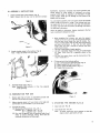
I1o COMPONENT
x19,5in.)
Solid State Ignition
Carburetor
Max, air volume
x19.3in,
hours, use the mixing ratio of between 15
are subject to change without notice,
IDENTIFICATION
Spout Pipe--
Fuel Tank
_Straigh%
Pipe
Straight Pipe Jr-L_
Cap,
U
_
Swivel
Joint
Recoil
)ark Plug
Air Cleaner
Thro_le
Lever
_Wing
Hose Band
Pipe
/
Bent Tube
Figure
1
III.
ASSEMBLY
I,
Attach
Note:
throttle
Ensure
WARNING:
INSTRUCTIONS
lever to the machine_ {Fig_ 2)
that the lever can be operated
normally
Experience
or using
leads to
during
Acidic
storage.
engine while
To avoid
'L
indicates
{called gasohot
moisture
which
that
alcohol
blended
fuels
ethanol
or methanol)
can attract
separation
and formation
of acids
gas can damage
the
fuel system
of an
in storage
engine problems,
the fuel system
should be emptied
before storage for 30 days or longer
Drain the gas tank, start
the engine and let it run until the fuel lines and carburetor
are empty. Use fresh fuel next season. See Storage
for additional
information.
Never
use engine
tank or permanent
or carburetor
cleaner
products
Instructions
in the
fuel
damage may occur
CAUTION:
When preparing
fuel mixture,
mix onty the amount
needed for the job you are to do Do not use fuel mixture
that has been stored longer than two (2) months.
Fuel
mixture
stored longer than this will cause hard starting
and poor performance
if fuel mix has been stored
longer than this time it should be removed
and filled
with a fresh mixture.
Use only a good grade of recJular gasoline,
Use only a reputable
brand of 2{ycte,
air cooled engine
oil,
Sears Chain
Saw Oil is especially
suited to this
engine,
For the first twenty
hours, use the mixing ratio of between 15 and 20 to 1,
Figure 2
2.
Attach
Note:
shoulder straps to the machine
{Fig_ 3)
Adjust the straps to fit your body.
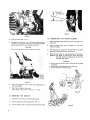
Fill the tank with fuel without
spilling°
(t) Do not fill fuel above fuel limit level, (Fig. 4)
(2) Wipe all spilled fuel with a dry cloth,
(3) Always attach the fuel strainer. (Fig° 11)
(4) Tighten fuel cap securely,
4_
Figure
3o
3
Assemble blower pipes, (Fig 1)
Note;
Assemble
pipes securely
,
while operating.
IV. PREPARATION
FOR
or
they
may
separate
USE
1,
Ensure again that all parts are assembled
that aft nuts and bolts are properly
tightened
2,
Adjust
shoulder straps to fit your body so that pads rest
comfortably
on your shoulder or you will be tired
3.
normally
Figure 4
and
Fuel and oil mixing
(1) Mixing ratio of fuel and oil: 2025 : 1
Example:
20 : t = gasoline 1 gal : oil 7 oz.
25 : 1 = gasoline 1 gal, : oil 6 oz,
(2) Pour half the gasoline into the container, add oil and
shake to ensure thorough
mixing,
Now add the
remainder
of gasoline and shake again
Vo STARTING
THE
1.
Open fuel cock,
2_
Ctose choke lever. [Fig. 5)
Note:
(Fig
ENGINE(Fig
5&6)
5)
In winter, c!ose fully,
but in summer
engine is warm, open partly or fully.
or when
the
UP
(High speed)
t
Throttle
lever
!
DOWN
(Low
speed)
Stow
Figure 7
Figure 5
Push up throttle
3.
4_
VII,
lever, (Fig° 7)
Holding the machine by your left hand and putting your
left foot on the machine frame, give a strong and straight
puii to recoil starter by your' right hand. (Fig 6)
OPERATING
Adjust
shoulder
your body.
it gently
with care_
POWER BLOWER
straps correctly
to make the machine
fit
2.
After
the engine fires,
without
inciiningo
3,
The velocity of air stream can be controlled from
breeze to a high-speed blast by throttle
lever,
4_
Select the best speed for each application of the blower,
Example: low speed for blowing dry leaves from lawn
and high speed for moving gravel or dirt from
driveway, (Fig. 8 & 9)
CAUTION
Do not putl off rope, but return
THE
put
the
machine
on your
back
a gentle
CAUTION
o
Do not point the blower pipe in the direction
of people
or animals,
e Always wear safety gtasses and use-a dust mask.
= Do not operate in unventilated
area.
Figure 6
5.
After the engine fires, open
duce engine speed
choke lever gradually
6.
Warm up the engine at low _peed
Note: winter:
about 5 min.. summer:
2 -
to re.
3 rain,.
Figure 8
VI. STOPPING
THE
throttle
ENGINE
1,
Push down
lever to reduce engine speed,.
2.
Stop the engine by pushing
3,
Put the machine
down
stop button.
on the ground
(Fig. 7)
and close fuel cock,
Figure 9
V!II,
CHECK
AND
MAINTENANCE
Air cleaner (Fig, 10)
(1) Remove
air cleaner cover and take out air filter.
(2) Accumulated
dust on the air filter will reduce engine
efficiency
and increase fuel consumption..
(3} Wash air filter and dry it wett_
CAUTION
Do not
filter,
use gasoline
and
inflammable
solvent
to clean the
Figure 12
4,
Carburetor
{Fig. !3)
(t) Carburetor
has been correctly adjusted at the factory
for optimum
performance,,
(2) To adjust idling speed, turn the throttle
stop screw
(turning
it clockwise
increases engine speed
turning it counterclockwise
reduces the speed].
(3}
Idling
speed must
constant speed.
be
adjusted
to
the
and
minimum
Air cleaner
Air cleaner
cover
filter
I
Figure 10
,
Fuel strainer (Fig, 11)
(t)
Fuel tank is fitted with a fuel strainer located under
filler
cap Do not remove this strainer when filling
the tank.,
(2) The strainer should
be removed
and cleaned
at
regular intervals,
Throttle
stop screw
Figure 13
5_ MUFFLER
.-------Fuet
tank
cap
deposits,
removed
..--------
Fuel strainer
"_._.. =,-_----- Packing B
AND
EXHAUST
PORT
(Fig.
14)
In the event _hat the engine should lose power and overheat,
the muffler
should be removed and checked for excessive
Carbon build up in the exhaust port should be
with a piece of wood, removing
that particles of
carbon deposits
complete
from
the muffler
unit in a suitable
flange
area and wash the
solvenL
Muffler
Figure 11
3,
Spark plug (Fig° 12)
(1} Clean or replace the plug if fouled with oily black
deposits,
(2) Replace the plug if the center electrode
is rounded
at the end or if the ground electrode is worn,,
(3) Adjust the gap 0,6 - 0 7 mm (.024 - ,028").
...... ..........
"
Spark arrester
Screw
Figure
14
IX. STORAGE
1.
AFTER
USE
5,
Correctly
preparing your Sears Power Blower for extended s_orage wil_ be amply rewarded by an increased service
life and trouble.free
performance_
2
Drain fuel tank and carburetor thoroughly,
Drain carburetor
through drain cock,
3.
Remove spark plug, pour one teaspoon
cylinder and pull recoil starter gently
oil. Replace spark plug securely,
Store
X_ TROUBLE
in a dry
atmosphere
and keep
out
of engine oil into
to distribute
the
fuel system
of
acids during
storage_ Acidic
of an engine while
To avoid _engine problems,
and coat unprotected
gas can damage
the fuel
storage of 30 days or longer.
system shoutd
Follow
be emptied
these instructions:
surfaces
and take the appropriate
action_
Table 1
Fuel
..............................
Fuel line hose clogged ............... Clean_
Piston& cylinder worn ............ Replace,
Fuel is not
reaching
m/tinder
o
_
Strainer c_ogged
Carburetor out of order
)
==
E
_
,E
o
5
=
_
w
._t
_=
"_
c
and check,
Ignitioncoil
M
c_o
c _in
0
Clean.
......... Oi_ssembte
_W_re connection defective ....... Reconnect
High_tenslon cord
connection defective
................ Repair as neces_ary_
condition
good
r
z_ =
,_
"o
is not
reaching
carburetor
=
r-
L_ °
r*
u
Insulator
U
cracked
........................ Replace plug.
w
• No spark at plug
._=
U_
Covered with carbon ................. Clean or replace.
Spark gap incorrect .................. Adiust,
Fouled with fuel ...............................
C_ean or repia_e
___
r_
_0
-_
Fue] does
not keep
_--
_
2
p
L_
E
"_
_
_
_
_ _
L-_
running
Start correctly
Fuel valve c)ogged with
dust
................................
Fuel p_sega in carburetor
clogged with dust
..................
Clean.
n --s .....
_d _=.ru_= and reD&ace,
fixing
___
Carburetor
does
surfaces
carburetor................
........ Replace.
Retighten.
not
work ofnormally
L-_
Crankcase and cylinder
pressure leaks
..........
u_u
L
Starting procedures
incorrect
.............................
Fuei leak;no from
Accelera,
tion and
low speed
function
defect,re
..........
Fuel inlet needle vatve
c)ogged with dust
...............
Carburetor
over fl_,_
Exhaust pipe sticky
with fuel
.....................
(
_}
Bearing damaged
Piston
m
and cylinder
the
in storage
SHOOTING
Refer to the chart to locate the problem
dust,
that alcohol b_ended fuels (called gasohol or using ethanot or
methanol}
can attract moisture which leads to separation and
before
Thoroughly
clean the unit
with oil to prevent rust,
unit
It is important
to prevent
gum deposits from forming
in
essential fuel system parts such as the carburetor,
fuel filter,
fuel hose_ or tank during
storage. Also, experience indicates
formatior_
4_
the
Stop leakage_
Clean,.
This is because fuel mtxlure
is; too rich_
Start the engine several times
with choke lever fully open_
...........................
Ofsassemble and replace
seized ...... Olsassemb(e and replace.
Crankshaft
worn .....................
Disassemb{e and replace,
Crankshaft
crankcase
contacting
t_; ......
...........................................
_,_.
and replace,
Table
2
lrn ro
'I
Engine
overheated
Spark
-------
--"
_J
Firing funcdon
defective
Carburetor
defective
P
er fuel
P
used
Use fuet with
'
"..............
plug defective
................................
As cooling
fi_sclog, air
pass well
................... _lean
f,
ms,
Excessive deposits in
0t
m-"
ncombustion chamber ..........' ......
sasse ote a o remove
!
F----
Plug damaged
;
:
L.---
Combustion
poor due to
defective
wiling
...................
Check wiring,
Needle
Readiust,,
setting
or fouled
........... Replace or clean,,
..... ,.............
overflow ................. Refer to Table 1,
clogged ................. Clean a_ necessary,,
Compression insufficient
{piston ring stuck or ...............
worn out)
_--
L
caroono
inc°trect
Carburetor
Air cleaner
Other
troubtes
_.,....
^.
/
L-.--_
=_C_
ratio,
of poor quality,
Re_t._ _
(burnt)
does not
correct mixing
Never use ga=oline
Disassemble, check and replac_
if necessary,
Cylinder chrome plating
Replace cylinder,
peeled or worn out
.................
Exhaust
carbon
port
clogged with
........................
Clean as nec_ssary_
Throttle
is not fully
Readiust,
o
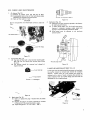
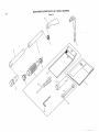
SEARS POWER BLOWER PARTS LIST - MODEL
636.796912
Figure t5
39
36
22
3O
24
2!
52
44
38
29
23
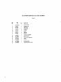
SEARS POWER BLOWER PARTS LIST - MODEL
Figure
KEY
NO,
2
3
4
5
6
7
8
9
10
11
12
PART
NO.
QTY.
NF04S-0150A
NF04S-1101
*RB
t
1
Muffler mounting
plate ass'¥
Volute case (frontl
N F04S-! 102-RB
N F04S-1104F
!
Voluse case (rear)
I
2
Ben I tube
Screw (MS x 67)
1
Engine cover
1
1
impeller
Cover
0
t
1
1
Plug
|repeller
Plug (rubber}
IA-RB
1
Frame compl.
N F04S-1107A
F L40-11098-PB
NF04S. 1114
N F04S-1115
FH04S-t 104
FL40-1110
0420 22998
F L40-201
spacer
13
FL40-2012A
1
Shoulder pad compl.
14
NF40-2101A
t5
EC02_083
2
t
Vibration-proof
rubber
Fuel lank cop ass°y (|ncl. t6}
16
17
EC02_644
FL40-3101A
1
1
Packing A
Fuel tank
t8
FL40-3102
19
FL40-5011
FL40-S012
I
1
Fuel-line
Throttle
2O
2t
22
23
24
25
26
27
EC02-720
00113 0618 0
1
1
4
3
00165
00218
0612 0
05O0 0
g
Nut
(MS)
00218
00218
0600 0
1000 0
5
Nut
(M.6)
1
NuL_!MIo
0400 0
1
Nut
00310
00311
00311
0500 0
0600 o
1oo0 o
4
B
Washer
Washer
Washer
(M5)
(M6)
(M10)
31
00312
00312
0500 0
0600 0
4
4
Washer
Washer
(M5}
(M6}
00320
00320
O4O0 0
0500 0
1
2
Spring washer
Spring washer
(M4}
(MS)
00320
0600 o
00320
00431
1000 0
05t4 0
10
t
Spnng washer
Spring washer
(M6)
(M 10)
00431
00435
05t2 0
0516 0
Screw (pan head)
:Screw (pan head)
Screw a_'v
(MS x 14)
(M5 x 12)
(M5 x 18}
34
35
36
37
38
39
4
t
7
QTY.
40
41
00431
00431
06t 0 0
0616 0
42
00628
3085 0
43
EC03-6103
44 _
45
FL40-3103
F L40-9106
46
47
0561 13998
064! 27999
48
49
50
EC05A-6111
RS0211-202B-RB
N B30K*6103
51
P503-5111
52
00436
05t2
2
0
Screw (pan head)
Screw (pan head)
I
1
0 ring
Fuel-llne
1
1
P1_te
Label
2
t
Clamp (Hose}
#
2
2
Packing
Pla_e
t
0
(M4)
DESCRIPTION
2
4
I
j_
Throttle wire
-SLop l_u _on
8o1_
(M6x 18)
Bolt
(M6 x 12)
00227
33
PART
NO.
hose
lever
28
29
3O
32
15
KEY
NO.
OESCRIPT!ON
636.796912
Fuel
(M6 x 10)
(M8 x 16}
hose prozecl|on
sIratner
Vibration-proof
Plug (rubber)
Screw ass'y
rubber
tube
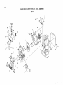
SEARS
POWER
BLOWER
PARTS
LIST-MODEL
636,796912
Figure 16
17
_:_1516
3
19
I
1
4O
48
2
44
20 •21
\
36
3O
29
28
37
31
\
24
23
\
32
27
26
\
38-39
5
SEARS POWER BLOWER PARTS LIST - MODEL
Figure
PART
NO.
KEY
NO.
!
2
3
EC04_072
0440 12999
i
1
t
0440
1
1
15997
4
0600 15988
5
6
7
EC03-071
0119 05994
0105 06994
B
ECO4JDt 25
0
2
0
0
1
4
6
1
Crank case ass'v (Incl.
Ballbearing
Crank case packing
Bob (socket head)
Clamp
Washer
52
00431
0510
0
1
53
00532
0320
0
Screw (pan head) (M5 x t0)
Woodruff
key
54
ECO4_379ATA
1
55
56
0043104100
0022704000
1
I
bracket
Reed bracket
Piston ring
Clip
1
1
Needle
Recoil
RecoiI
Starter
packing
4
Boll (socket head} (MS x 18)
Crank shall ass'y
Piston
pin
bearing
starter compI. {Incl. 21 thru24!
starter ass'y (incl. 25 thtu 33 |
case B
EC04-0513A
A50103212700
1
I
243051821009
451050600009
4
4
26
A54103200100
A55003210001
1
1
27
A60003200000
1
Spiral spring
28
29
A60102600000
A5600260029t
1
!
Frtction
Frici|on
30
31
141051251002
I
Bind screw
A60503210000
!
A57120950000
A57202700000
1
1
Return spring
Statler rope
EC04-0378
EC04-3122
1
I
00433 0520 0
F L40-910512A
3
!
EC04-0718A
11100100100
1
1
37
38
39
Screw
(MS x 18)
Washer
Reel
(M5}
Ratchet
spring
plate
(M5 x 12)
Starter knob
Muffler compl.
Mu f fief gasket
S_rew ass'y (M5 x 20}
Label (model)
Magneto comp{. (incl. 39. 401
Flywheel
(M8)
1
I
2
2
35
36
Spring washer
Nut (M6)
Washer (MS|
0
0
EC04-2 t 0A
O565 11999
33
34
6
1
0566 05998
00310 0500
I
1
32
0600 0
0800 0
50
51
1
23
00218
00310
packing
EC04-206/28
EC04-207A
24
25
Spark plug
Nut {left} {M8)
2
t
EC04-0222
22
I
1
6
15
1
1
0
0
0
13
14
0610 12996
EC04-0516A
0
0420 0
0310 0
0119 05995
20
2t
14995
0t70 08996
0203 08999
0600
Reed ass'y
Carburetor
18
19
0650
43
44
-
Ignition coil
Plug cap
00434
00532
Cylinder
0
42
45
46
1
1
00320
1
Piston
11400331000
KM61_B8e
DESCR IPTION
47
!
16
t7
40
41
QTY.
48
49
EC04-091A
0
(M5 x 30|
PART
NO.
cornpt. (Incl. 7)
EC03-I09A
!
2
7)
Stud {M6)
9
EC04-t{ 04c
E C03-115
2 Ihru
Oil seal (front}
Oil seal (rear)
Cylinder
t6
KEY
NO,
DESCRIPTION
10
11
12
o_
QTY.
636.796912
t
Spring washer (M6)
Screw ass'V (M4 x 20)
Woodruff
key
(M5)
Spark attester
Screw (pan head) {M4 x 10)
Nut (M4)
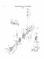
SEARS
POWER
BLOWER
PARTS
LIST-
MODEL
636.796912
Figure t 7
33
27
26
/
35
29
1
18
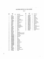
SEARS POWER BLOWER PARTS LIST- MODEL
Figure
KEY
NO.
!
2
3
4
5
6
7
8
9
1t
12
13
14
15
16
t7
_8
t9
20
21
PART
NO.
QTY.
I
t
1
!
!
1
EC04-O682A
CKI31
832-16001
J8-3 N05
MDt4140
VM14ci,/38b
VMI5124A
VMI6/200
VM12143
MD13/44
M21/t5
VM241148
Nt02-22t
VMt 5/I 73
VM15/353
VM151264
VM15/351
VM131139
852-00031
EC03-S0Ol
22
VM13i68A
VM131326
23
B2--0830
0
24
B34183
25
26
VM131215
VM15/331
27
VM18i164A
28
CW2_0416
29
VMI51348
30
31
32
VM13/210
CW2"0414
EC04-O335B
33
0736
34
00436 0410 0
EC04-3304A
35
36
36998
EC04-3305
0
1
1
1
1
1
1
!
1
1
1
1
I
1
1
1
I
I
1
1
1
1
2
1
1
2
1
1
4
1
2
DESCRIPTION
Carburetor
compl.
(Incl.
2 thru 31}
Cock body ass'y
Piston _r_lve (#1"0)
Jet needle
E ring
Spring seat
Spring
Top
Cap
Cable guide
Cable _djuster
lock
nut
Cable adjuster
Main jet (#77.5)
Needle ass*y
Float arm
Float pin
Gasket
Float
Float chamber body
Guido screw assay
O ring
Clip
Bolt
Washer
Nut
Spring
Throttle
stop screw
Spring washer cross screw
Gasket
Filter
Spring we=her cross screw
Air cleaner oss'y (Incl. 33, 35, 36)
Labe_
Screw ass'y (M4 x tO)
Air cleaner cap
Element
17
636.796912
SEARS POWER BLOWER PARTS LIST - MODEL
Figure
636.796912
I8
°\
\
\
7
\
I1
SEARS POWER BLOWER PARTS LIST - MODEL
Figure 18
PART
NO,
KEY
NO.
3
4
N F04S_09031t
FL40-9001
N F31-097B
N F04S-9121
5
F L40-9120
6
7
F L40-9121
t
2
8
9
10
1t
12
..&
-M
NF40-7120
FL40-9012
FL40-9014
0717 04999
OTY.
DESCRIPTION
1
1
I
Wing hose band (big)
Shou|dor band ass'y
t
2
Corrugated
1
1
Wing hose band
pipe
Straight pipe
End pipe
Hose clamp
Swivel joint
Tool kit (Inc1.10,12
0
1
1
1
1
t
t
Owner's manual (FL40-9107!4)
00994 0
06999 0
6619501201
13
0700
0715
14
15
07t3 21999
07t 0 08999
0
0
thrul 5)
Wrench (socket head}
1
Tool bag
PLus driver
Box wrench(21
I
Double,end
MiM )
wrench (8 x t0 M/M)
636.796912
OWNER'S
MANUAL
SEARS POWER BLOWER
1N
The model number of your power blower is
located on the label on recoil starter of the
engine.
The serial number of your power blower
located on the label on the fan housing.
2_
MODEL NO.
636.796912
HOW
When ordering
repair
following
information:
(1)
(2)
Model number:
Name of item:
(3)
Part number
(4)
Part description
parts,
always
is
give the
636.796912
37.7 cc GAS POWER
B LOWE R
TO ORDER
3,
REPAIR
PARTS
All parts listed may be ordered from any Sears
Service Center or most Sears stores.
(1)
If the parts you need are not stocked
Iocally, your order wilt be electronically
transmitted to a Sears Repair' Parts Distribution Center for' handling,
I
6619501201
Sold by Sears, Roebuck and Co,, Chicago, IL60684
U.S.A.
Printed in Japan