1
Owner's Manual
ROTARY LAWN MOWER
6.5 Horsepower
Power-Propelled
21" Multi-Cut
Model No.
917.377844
• EspaSol, p. 20
CAUTION:
Read and follow all
Safety Rules and instructions
before operating this equipment
Sears, Roebuck and Co., Hoffman Estates, IL 60179
Visit our Craftsman website: wwwosearscom/crafisman
U.S.A.
Warranty ...................................................
2
Safety Rules ..........................................
2-4
Product Specifications .............................. 4
Assembly / Pre-Operation ..................... 5-6
Operation ............................................
7-11
Maintenance Schedule ........................... 12
Maintenance ........................................
Service and Adjustments ...................
Storage ..............................................
Troubleshooting .................................
Repair Parts .......................................
Sears Service .......................... Back
12-15
15-_17
17-18
18-19
38-47
Cover
LIMITED TWO YEAR WARRANTY ON CRAFTSMAN POWER MOWER
For two years from date of purchase, when this Craftsman Lawn Mower is maintained,
lubricated, and tuned up according to the operating and maintenance instructions in the
owner's manual, Sears will repair free of charge any defect in material or workmanship.
If this Craftsman Lawn Mower is used for commercial
applies for only 90 days from the date of purchase.
or rental purposes,
this warranty
This Warranty does not cover:
• Expendable items which become worn during normal use, such as rotary mower
blades, blade adapters, belts, air cleaners and spark plug.
° Repairs necessary because of operator abuse or negligence, including bent crankshafts and the failure to maintain the equipment according to the instructions contained in the owneCs manual.
Warranty service is available by returning the Craftsman power mower to the nearest Sears
Parts & Repair Center in the United States. This warranty applies only while this product
is used in the United States.
This Warranty gives you specific legal rights, and you may also have other rights which
vary from state to state.
Sears, Roebuck And Co., D/817 WA, Hoffman
Estates, IL 60179
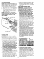
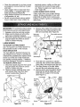
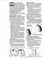
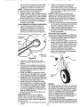
IMPORTANT: ']'his cutting machine is capable of amputating hands and feet and throwing objects. Failure to observe the following safety instructions could result in serious injury or death.
,& CAUTION:
Muffler and
ALook for this symbol to point out important
safety precautions. It means CAUTION! BE- other engine parts become
COMEALERT!YOU RSAFETYIS INVOLVED.
extremely hot during
AWARNING:
In order to prevent accidental
operation and remain hot
starting when setting up, transporting, ad- after' engine has stopped. To
justing or making repairs, always disconnect
avoid severe burns on contact,
spark plug wire and place wire where it cannot
stay away from these areas.
come in contact with plug.
I. GENERAL
OPERATION
AWARNING:
Engine exhaust, some of its
* Read, understand, and follow all
constituents, and certain vehicle components
instructions on the machine and in the
contain or emit chemicals known to the State
of Californiato cause cancer and birth defects
manual(s) before starting° Be thoroughly
familiar
with the controls and the proper
or other reproductive harm.
use of the machine before starting.
,&WARNING: Battery posts, terminals and
related accessories contain lead and lead
° Do not put hands or feet near or under
rotating parts. Keep clear of the discompounds, chemicals known to the State
of California to cause cancer and birth
charge opening at all times.
Only allow responsible individuals, familiar
defects or other reproductive harm. Wash
withtheinstructions,tooperatethernachine.
hands after handling.
2
Q
• Clear the area of objectssuch as rocks,
toys, wire, bones, sticks,etc,.,which
could be picked up and thrownby blade.
° Be sure the area is clear of other people
before mowing. Stop machine if anyone
enters the area.
• Do not operate the mower when barefoot or wearing open sandals. Always
wear substantial foot wear.
° Do not pull mower backwards unless absolutely necessary. Always look down and
behind before and while moving backwards,
° Never direct discharged material toward
anyone. Avoid discharging material against
a wall or obstruction. Material may richochet back toward the operator. Stop the
blade when crossing gravel surfaces.
° Do not operate the mower without
proper guards, plates, grass catcher or
other safety protective devices in place.
° See manufacturer's instructions for
proper operation and installation of
accessories. Only use accessories approved by the manufacturer.
• Stop the blade(s) when crossing gravel
drives, walks, or roads.
• Stop the engine (motor) whenever you
leave the equipment, before cleaning the
mower or unclogging the chute.
° Shut the engine (motor) off and wait until
the blade comes to complete stop before
removing grass catcher.
° Mow only in daylight / good artificial light.
• Do not operate the machine while under
the influence of alcohol or drugs.
° Never operate machine in wet grass.
Always be sure of your footing: keep a
firm hold on the handle; walk, never run.
• Disengage the self-propelled mechanism or drive clutch on mowers so
equipped before starting the engine.
° If the equipment should start to vibrate
abnormally, stop the engine (motor) and
check immediately for the cause. Vibration is generally a warning of trouble.
• Always wearsafetygoggles
orsafety glasses with side shields when operating mower.
I1. SLOPE OPERATION
Slopes are a major factor related to stip &
fall accidents which can result in severe injury. All slopes require extra caution. If you
feel uneasy on a slope, do not mow iL
DO:
° Mow across the face of slopes: never
up and down. Exercise extreme caution
when changing direction on slopes.
° Remove obstacles such as rocks, tree
limbs, etc.
° Watch for holes, ruts, or bumps° Tall
grass can hide obstacles°
3
DO NOT:
° Do not trim near drop-offs, ditches or
embankments. The operator could lose
footing or balance.
° Do not trim excessively steep slopes.
• Do not mow on wet grass° Reduced footing could cause slipping.
III. CHILDREN
Tragic accidents can occur if the operator
is not alert to the presence of children°
Children are often attracted to the machine
and the mowing activity. Never assume
that children wilt remain where you last
saw them.
- Keep children out of the trimming area
and under the watchful care of another
responsible adult.
- Be alert and turn machine off if children
enter the area°
- Before and while walking backwards,
look behind and down for small children.
- Never allow children to operate mower,
• Use extra care when approaching blind
corners, shrubs, trees, or other objects
that may obscure vision.
IV. SAFE
HANDLING
OF GASOLINE
Use extreme care in handling gasoline.
Gasoline is extremely flammable and the
vapors are explosive,.
• Extinguish all cigarettes, cigars, pipes
and other sources of ignition,
- Use only an approved container.
• Never remove gas cap or add fuel with
the engine running. Allow engine to coot
before refueling°
o Never refuel the machine indoors.
° Never store the machine or fuel container where there is an open flame, spark
or pilot light such as a water heater or on
other appliances.
• Never fill containers inside a vehicle, on
a truck or trailer bed with a plastic liner,
Always place containers on the ground
away from your vehicle before filling.
• Remove gas-powered equipment from
the truck or trailer and refuel it on the
ground. If this is not possible, then
refuel such equipment with a portable
container, rather than from a gasoline
dispenser nozzle_
. Keep the nozzle in contact with the rim
of the fuel tank or container opening at
all times until fueling is complete. Do not
use a nozzle lock-open device.
o
If fuel is spilled on clothing, change
clothing immediately.
Never overfill fuel tank. Replace gas cap
and tighten securely.
°
V. GENERAL
SERVICE
= Never run machine inside a closed area.
• Never make adjustments or repairs with
the engine (motor) running. Disconnectthe
spark plug wire, and keep the wire away
from plug to prevent accidental starting.
o Keep nuts and bolts, especially blade
attachment bolts, tight and keep equipment in good condition.
o Never tamper with safety devices, Check
their proper operation regularly.
° Keep machine free of grass, leaves, or
other debris build-up. Clean oil orfuel spillage. Allow machine to cool before storing.
° Stop and inspect the equipment if you
strike an object. Repair, if necessary,
before restarting.
o Never attempt to make wheel height
adjustments while the engine is running.
° Grass catcher components are subject
to wear, damage, and deterioration,
which could expose moving parts or
allow objects to be thrown. Frequently
check components and replace with
manufacturer's recommended parts,
when necessary.
= Mower blades are sharp and can cut.
Wrap the blade(s) or wear gloves, and
use extra caution when servicing them.
= Do not change the engine governor setting or overspeed the engine.
• Maintain or replace safety and instruction labels, as necessary°
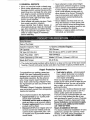
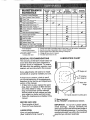
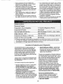
Serial Number:
Date of Purchase:
Gasoline Capacity / Type:
1.0 Quarts (Unleaded
Oil Capacity:
18.5 Ounces
Oil Type (API SG-SL):
SAE 30 (above 32°F) or SAE 10W-30
Spark Plug (Gap: _030")
NGK BPR6ES
Valve Clearance
Intake: 0.015 mm; Exhaust: 0.020 mm
(± 0.04 mm):
Blade Bolt Torque:
Regular)
35-40 ft. lbs.
° The model and serial numbers will be found on a decal on the rear of the lawn mower
housing° Record both serial number and date of purchase in space provided above.
Repair Protection
Congratulations on making a smart purchase. Your new Craftsman@ product is
designed and manufactured for years of
dependable operation. But like all products, it may require repair from time to
time. That's when having a Repair Protection Agreement can save you money and
aggravation.
Purchase a Repair Protection Agreement
now and protect yourself from unexpected
hassle and expense.
Here's what's included in the Agreement:
°
Expert service by our 12,000 profeo
sional repair specialists_
,
Unlimited service and no charge for
parts and labor' on all covered repairs.
•
Product replacement
if your covered
product can't be fixed.
= Discount of 10% from regular price of
service and service-related
parts not
covered by the agreement; also, 10%
off regular price of preventive maintenance check_
Agreements
o
Fast help by phone - phone support
from a Sears technician on products
requiring in-home repair; plus convenient repair scheduling.
Once you purchase the Agreement, a
simple phone call is all that it takes for you
to schedule service. You can call any'Lime
day or night, or schedule a service appointment online.
Sears has over 12,000 professional repair
specialists, who have access to over 4_5
million quality parts and accessories.
That's the kind of professionalism you can
count on to help prolong the life of your
new purchase for years to come. Purchase
your Repair Protection Agreement today!
Some limitations and exclusions apply.
For prices and additional information
call 1-800-827-6655.
Sears Installation
Service
For Sears professional installation of home
appliances, garage door openers, water
heaters, and other major home items, in
4 the U.S.A. call 1-800-4-MY-HOME@.
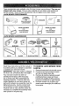
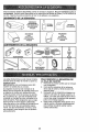
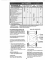
These accessories were availablewhen this lawn mowerwas produced. They are not
shipped with your mower. They are also available at most Sears retail outlets and
service centers. Some of these accessories may not apply to your lawn mower.
LAWN MOWER
PERFORMANCE
CLIPPING
DEFLECTORS
FOR
REAR DISCHARGE
LAWN MOWERS
STABILIZER
iiii
GRASS CATCHERS
FOR
REAR DISCHARGE
LAWN MOWERS
LAWN MOWER
_-'_t
i,
...............
GRASS FOR
CATCHERS
LAWN MOWERS
SIDE D_SCHARGE
MAINTENANCE
MUFFLERS
AIR FILTERS
ii
..... SPARK PLUGS.....
i t
BELTS
BLADES
BLADE ADAPTERS
Read these instructions and this manual in
its entirety before you attempt to assemble
or operate your new lawn mower.
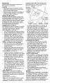
IMPORTANT: This lawn mower is shipped
WITHOUT OIL OR GASOLINE in the engine.
Your new lawn mower has been assembled at the factory with the exception of those parts left unassembled for
shipping purposes. To ensure safe and
proper operation of your lawn mower, all
parts and hardware you assemble must be
tightened securely, Use the correct tools
as necessary to ensure proper tightness.
All parts such as nuts, washers, bolts, etc.,
necessary to complete the assembly have
been placed in the parts bag°
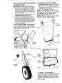
TO REMOVE
CARTON
WHEELS
LAWN
ENGINE OIL
MOWER
FROM
1. Remove loose parts included with mower,
2. Cut down two end corners of carton
and lay end panel down flat,
3. Remove all packing materials except
padding between upper and lower
handle and padding holding operator
presence control bar to upper handle.
4, Roll lawn mower out of carton and
check carton thoroughly for additional
loose parts,
5
HOWTO SET UPYOUR LAWN MOWER
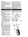
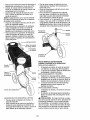
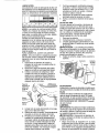
TO ASSEMBLE
TO UNFOLD
1. Slide grass catcher bag over' the frame.
Make sure the rear handle is on top
(the same side as the front handle) and
the strap is on the bottom.
2. Slip vinyl bindings over frame.
NOTE: If vinyl bindings are too stiff, hold
them in warm water for a few minutes. If
bag gets wet, let it dry before using.
3, Close grass catcher door:
NOTE; When fully closed, door will "snap"
shut over frame and vinyl bindings.
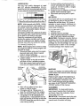
HANDLE
IMPORTANT: Unfold handJe carefully so
as not to pinch or damage control cables.
I, Raise lower handle section to operating position and align hole in handle
with one of the height positioning holes
in handle bracket.
2. Insert handle bolt through handle and
bracket and secure with knob.
3. Repeat for opposite side of handle.
4. Remove protective padding, raise upper handle section into place on lower
handle and tighten both handle knobs.
5. Remove any packing material from
around control bar:
Your lawn mower handle can be adjusted
for your mowing comfort, Refer to "ADJUST HANDLE" in the Service and Adjustments section of this manual.
GRASS CATCHER
\
handle
Operator presence
control bar
\
\
\
\
\
\\
LIFT
Front
\\
\
Mowing
position
Lower handle
Grass
catcher'
frame
Bolt
Knob
/
Vinyl
\
/
Handle
bracket
TO INSTALL A'I-rACHMENTS
6
Your lawn mower was shipped ready to be
used as a mulcher. To convert mower to
bagging or discharging, see '%0 CONVERT MOWER" in the Operation section
of this manual.
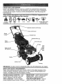
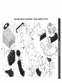
KNOW YOUR LAWN MOWER
READ THIS OWNER'S MANUAL AND ALL SAFETY RULES BEFORE OPERATING
YOUR LAWN MOWER° Compare the illustrations with your lawn mower to familiarize
yourself with the location of various controls and adjustments,
Save this manual for
future reference.
ul
J
,llll,ul_uu
i
....
.11....
.,,.,j,j,,..w
.r
%_.I
These symbols may appear on your lawn mower or in literature
product. Learn and understand their meaning.
CAUTION
OR WARNING
ENGINE
ON
,,,
ENGINE
OFF
H
FAST
SLOW
r_
FUEL
CHOKE
.,
p.i
OIL
,,,,_u
l,
supplied
_ i
with the
DANGER, KEEP HANDS
AND FEET AWAY
1,4_IIW,
,
pq
I"',,'11''
Operator presence control bar
Drive control lever
Starter
handle
Gasoline filler cap
Grass
Fuel valve lever
catche
Air filter
Dual
point
height
adjuster
lever
Engine oil cap
with di
Muffler
Mulcher door
Housing
IMPORTANT:
i
,
This lawn mower is shipped WITHOUT
i,,,,,,i,iiii
ii,
I,
,
OIL OR GASOLINE
,i
in the engine,
,i
J
MEETS CPSC SAFETY REQUIREMENTS
Sears rotary walk-behind power lawn mowers conform to the safety standards of the
American National Standards Institute and the U,S. Consumer Product Safety Commission. The blade turns when the engine is running.
I
I//_
,,
i,ii1,1,,,,, i
,1'iiiii
ii
i, ,i,,
,
Operator presence control bar - must
be held down to the handle to start the
engine. Release to stop the engine.
Drive control lever - used to engage
power-propelled forward motion of mower.
ii1,,
ii
,
Starter handle - used for starting engine,
Mulcher door - allows conversion to
discharging or bagging operation_
Dual point height adjusterused to
adjust cutting height of lawn mower.
7
The operation of any lawn
mower can result in foreign
objectsthrown into the
eyes, which can result in
severeeye damage.Always
wear safetyglasses or eye shields while
operating your lawn mower or performing....
any adjustments or repairs.We recommend a standard safety glasses or wide
vision safety mask worn over spectacles.
HOW TO USE YOUR
LAWN
MOWER
ENGINE SPEED
The engine speed was set at the factory
for optimum performance. Speed is not
adjustable.
ENGINE ZONE CONTROL
,&CAUTION:
Federal regulations require
an engine control to be installed on this
lawn mower in order to minimize the
risk of blade contact injury. Do not under
any circumstances attempt to defeat the
function of the operator control. The blade
turns when the engine is running.
• Your lawn mower is equipped with an
operator presence control bar which
requires the operator to be positioned
behind the lawn mower handle to start
and operate the lawn mower.
DRIVE CONTROL
• Self-propelling is controlled by holding the operator presence control bar
down to the handle and pulling the drive
control lever rearward to the handle.
The farther toward the handle the lever
is pulled, the faster the unit will travel.
• Forward motion will stop when either
the operator presence control bar or
drive control lever are released. To stop
forward motion without stopping engine,
release only the drive control lever. Hold
operator presence control bar down
against handle to continue mowing
without self-propelling.
NOTE; If after releasing the drive control
the mower' witl not roll backwards, push
the mower' forward slightly to disengage
drive wheels.
O _=ratorpresence control bar
o To keep drive control engaged when
turning corners, push down on the
handle to lift the front wheels off the
ground while turning lawn mower.
DRIVE CONTROL ADJUSTMENT
Over time, the drive control system may become "loose", resulting in decreased speed°
There is a button on the underside of the drive
control housing to increase tension on the
drive cable. Proceed as follows:
1. Turn mower engine off and disconnect
spark plug wire from spark plug.
2. Pull out button on underside of drive
control, then push it back in.
3. Operate mower to see if drive speed
has increased. If there is no increase,
the drive belt is worn and needs to be
replaced.
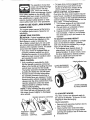
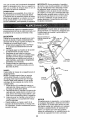
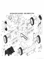
TO ADJUST CUTTING HEIGHT
Both front wheels are adjusted by a single
lever on the left front wheel. Likewise,
both rear wheels are adjusted by a single
lever on the left rear wheel.
= Pull adjuster lever toward wheel. To
raise mower, move lever forward to
desired position. To lower mower, move
the lever backward to desired position.
Be sure to adjust both front and rear
wheels to the same height.
Height
uster lever
LEVER BACKWARD
TO LOWER MOWER
LEVER FORWARD
TO RAISE MOWER
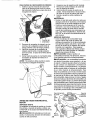
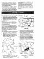
TO CONVERT
MOWER
Your lawn mower was shipped ready to
be used as a mulcher. To convert to rear
bagging or side discharging:
REAR BAGGING
Adjustment
button (on
underside)
TO
ENGAGE
DRIVE
CONTROL
Drive
control
lever
DRIVE
CONTROL
DISENGAGED
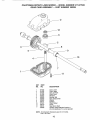
o Remove knob securing mulcher door to
lawn mower housing.
, Open mutcher door and insert tabs
of discharge chute into hinge bracket
opening and position rear of chute over
threaded stud.
SIDE DISCHARGING
Hinge bracket
Mulcher door
° Secure rear of discharge chute to lawn
mower housing with knob.
o Place rear handle of grass catcher on
the crossbar of the lawn mower's lower
handle as shown.
• Lift the round door of the discharge
chute and place the grass catcher into
place on the discharge chute.
NOTE: Be sure round door of discharge
chute rests on grass catcher as shown.
o Mower is now ready for rear bagging
operation.
• To convert to mulching operation,
remove grass catcher and discharge
chute. Secure mulcher door to mower
housing with knob.
• To convert to side discharging operation, remove grass catcher and discharge chute. Install side discharge
deflector and secure it to lawn mower
housing with knob.
Crossbar
Grass
Round
door
chute
Threaded
stud
Mulcher door
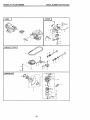
o Grass catcher and discharge chute
must be removed.
o Open mulcher door and install front of
side discharge deflector beneath door
and position rear over threaded stud.
o Secure rear of side discharge deflector
to lawn mower housing with knob.
o Mower is now ready for side discharging
operation.
° To convert to mulching operation, side
discharge deflector must be removed
and mulcher door secured to mower
housing with knob.
o To convert to rear bagging operation, side discharge deflector must be
removed; discharge chute and grass
catcher installed and discharge chute
secured to mower housing with knob.
Mulcher door
- Knob
\
stud
Side
discharge
deflector
SIMPLE STEPS TO REMEMBER WHEN
CONVERTING YOUR LAWN MOWER
FOR MULCHING 1. Grass catcher, discharge chute and
side discharge deflector removed.
2. Mulcher door secured to mower housing with knob.
FOR REAR BAGGING 1. Side discharge deflector removed°
2. Grass catcher and discharge chute
installed with discharge chute secured
to lawn mower housing with knob.
3. Round door of discharge chute resting
on top of grass catcher.
FOR SIDE DISCHARGING !. Grass catcher and discharge chute
removed.
2. Side discharge deflector installed and
secured to mower housing with knob.
_CAUTION:
Do not run your lawn mower
without mulcher door closed; side discharge deflector installed, or discharge
chute and approved grass catcher in
place. Never attempt to operate the lawn
mower with mulcher door or round door
removed or propped open.
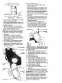
TO EMPTY GRASS CATCHER
1. Open round door of discharge chute to
move starter rope out and away from
grass catcher.
Round
door
Starter
rope
2. Remove grass catcher with clippings
from lawn mower using both front and
rear handle&
3. Empty clippings from grass catcher
using both rear handle and strap. "['he
weight of the grass will open the door.
4. Snap door shut over frame before
installing grass catcher on mower.
NOTE: Do not drag the grass catcher when
emptying; it will cause unnecessary wear=
Rear
handle
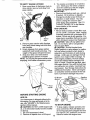
3o You receive a container of oil with the
unit. Slowly pour the entire container
down the oil fill spout into the engine.
4. insert and tighten dipstick.
IMPORTANT:
= Check oil level before each use° Add oil
if needed. Fill to full line on dipstick.
o Change the oil after every 25 hours of
operation or each season. You may
need to change the oil more often
under dusty, dirty conditions. See 'q_O
CHANGE ENGINE OIU' in the Maintenance section of this manual.
ADD GASOLINE
o Fill fuel tank to bottom of tank filler neck.
Do not overfill. Use fresh, clean, regular
unleaded gasoline with a minimum of 87
octane. Do not mix oil with gasoline. Purchase fuel in quantities that can be used
within 30 days to assure fuel freshness.
_b. CAUTION: Wipe off any spilled oil or
fuel. Do not store, spill or use gasoline
near an open flame.
CAUTION: Alcohol blended fuels
(called gasohol or using ethanol or methanol) can attract moisture which leads to
separation and formation of acids during
storage. Acidic gas can damage the fuel
system of an engine while in storage. To
avoid engine problems, the fuel system
should be emptied before storage of 30
days or longer. Empty the gas tank, start
the engine and let it run until the fuel lines
and carburetor are empty. Use fresh fuel
next season. See Storage Instructions for
additional information. Never use engine
or carburetor cleaner products in the fuel
tank or permanent damage may occur.
Oil fill cap /
di
Gasoline
filler cap
Front
handle
BEFORE
STARTING
ENGINE
ADD OIL
Your lawnrnower is shipped without oil in
the engine. For type and grade of oil to
use, see "ENGINE" in the Maintenance
section of this manual.
_k CAUTION; DO NOT overfill engine with
oil, or it wilI smoke heavily from the muffler
on startup.
1. Be sure tawnmower is level.
2. Remove oil dipstick from oit fill spout.
Upper
mark
Lowe
mark
TO STOP
10
ENGINE
o To stop engine, release operator presence control bar. Wait until blade and
atl moving parts have stopped and turn
fuel valve to OFF position if you do not
intend to restart the engine soon.
TO START ENGINE
NOTE: Due to protective coatings on the
• Keep top of engine around starter clear
and clean of grass clippings and chaff.
This will help engine air flow and extend
engine life.
engine, a small amount of smoke may be
present during the initial use of the product and should be considered normal.
1. Be sure fue! valve is in the ON position_
2o Move choke lever to ON (N) position.
3. Hold operator presence control bar
down to the handle and pull starter
handle quickly. Do not allow starter
rope to snap back.
NOTE: The choke lever automatically
begins moving to the OFF position when
operator presence control bar is held
down to handle.
OFF
MULCHING
TIPS
IMPORTANT:
For best performance,
keep mower housing free of built-up
grass and trash. See "CLEANING" in the
Maintenance section of this manual.
= The special mulching blade will recut
the grass clippings many times and
reduce them in size so that as they fall
onto the lawn they will disperse into
the grass and not be noticed. Also, the
mulched grass will biodegrade quickly
to provide nutrients for the lawn. Always
mulch with your highest engine (blade)
speed as this will provide the best recutting action of the blades.
° Avoid cutting your lawn when it is wet_
Wet grass tends to form clumps and
interferes with the mulching action. The
best time to mow your lawn is the early
afternoon. At this time the grass has
dried, yet the newly cut area will not be
exposed to direct sunlight°
° For best results, adjust the lawn mower
cutting height so that the lawn mower
cuts off only the top one-third of the
grass blades. If the lawn is overgrown it
will be necessary to raise the height of
cut to reduce pushing effort and to keep
from overloading the engine and leaving
clumps of mulched grass. For extremely
heavy grass, reduce your width of cut
by overlapping previously cut path and
mow slowly_
lever
Fuel valve lever
MOWING TIPS
CAUTION:
Do not use de-thatcher
blade attachments on your mower. Such
attachments are hazardous, will damage
your mower and could void your warranty.
= Under certain conditions, such as very
tall grass, it may be necessary to raise
the height of cut to reduce pushing
effort and to keep from overloading the
engine and leaving clumps of grass clippings, it may also be necessary to reduce ground speed and/or run the lawn
mower over the area a second time.
= For extremely heavy cutting, reduce the
width of cut by overlapping previously
cut path and mow slowly.
o For better grass bagging and most cutting conditions, the engine speed should
be set in the FAST position.
• Pores in cloth grass catchers can become filled with dirt and dust with use
and catchers will collect less grass° To
prevent this, regularly hose catcher off
with water and let dry before using_
MOWING
1/3
1t
° Certain types of grass and grass
conditions may require that an area be
mulched a second time to completely
hide the clippings. When doing a second cut, mow across (perpendicular) to
the first cut path.
° Change your cutting pattern from week
to week. Mow north to south one week
then change to east to west the next
week_ This will help prevent matting and
graining of the lawn.
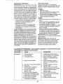
MAINT NAN@E
BEFORE
EACH
USE
Check for Loose Fasteners
v'
AFTER ] EVERY
EACH I
10
USE ] HOURS
EVERY
100
HOURS
BEFORE
STORAGE
v'
v'
,/j
"-' Clean / Inspect Grass Catcher *
A I Check Tires
Wl
EVERY
25 HOURS
OR SEASON
v'
N I Check Drive Wheels ***
Clean Lawn Mower ....
MI Clean under Drive Cover "'*
, q
Ot Check Drive Belt/Pulleys
***
WI Check / Sharpen / Replace Blade
] Lubrication
--
v'
v'
i
RI
Cfean and Recharge Battery **
Check Engine Oil level
i
Change Engine Oil
N: Clean Air Filter
G inspect Muffler
i
H Replace Spark Plug
E Replace Air Filter Paper Cartridge
v_
v'
v"
14
v'
Empty fuel system or add Stabilizer
* (if so equipped)
** Electric-Start mowers
*** Power-Propelled
mowers
**** Use a scraper
to dean under deck
GENERAL
1
2
3
4
5
- Change more often if operating under a heavy toad or in high outdoo_temperatures.
- Service more often if operating in dirty or dusty condition&
- Replace blades more often when mowing in sandy soil
- Charge 48 hours at end of season
- And after each 5 hours of use,
LUBRICATION
RECOMMENDATIONS
CHART
The warranty on this lawn mower does not
cover items that have been subjected to
operator abuse or negligence. To receive
full value from the warranty, operator must
maintain unit as instructed in this manual.
Engine oil
Some adjustments wilt need to be made
periodically to properly maintain your unit.
(_ Mulcher
At least once a season, check to see if
you should make any of the adjustments
described in the Service and Adjustments
section of this manual.
o At least once a year, replace the spark
plug, clean or replace air filter element
and check blade for wear. A new spark
plug and clean!new air filter element
assure proper air-fuel mixture and help
your engine run better and last longer.
o Follow the maintenance schedule in this
manual.
door hinge pin
tO Rear door
hinge
(_) Handle bracket mounting pins
_
BEFORE
EACH USE
° Check engine oil level.
Check for loose fasteners.
LUBRICATION
Keep unit welt lubricated
(See "LUBRICATION CHART")°
Spray
lubricant in Maintenance
See "ENGINE"
section.
IMPORTANT:
Do not oil or grease plastic
wheel bearings.
Viscous lubricants will
attract dust and dirt that will shorten the life of
the self-lubricating bearings. If you feel they
must be lubricated, use only a dry, powdered
1 2graphite
type lubricant sparingly.
LAWN MOWER
Always observe safety rules when performing any maintenance.
TIRES
• Keep tires free of gasoline, oil, or insect
control chemicals which can harm rubber°
o Avoid stumps, stones, deep ruts, sharp
objects and other hazards that may
cause tire damage.
DRIVE WHEELS
Check rear drive wheels each time you
mow to be sure they move freely. The
wheels not turning freely means trash,
grass cuttings, etc., may be inside the
drive wheel and dust cover area and must
be cleaned out to free drive wheels.
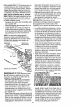
BLADE CARE
For best results, mower blade must be kept
sharp. Replace a bent or damaged blade.
The blade can be sharpened with a file
or on a grinding wheel. Do not attempt
to sharpen while on the mower.
To check blade balance, drive a nail into
a beam or wall. Leave about one inch of
the straight nail exposed. Place center
hole of blade over the head of the nail.
If blade is balanced, it should remain in
a horizontal position. If either end of the
blade moves downward, sharpen the
heavy end until the blade is balanced°
Trailing
Blade adapter,
TO REMOVE BLADE
1. Disconnect spark plug wire from spark
plug and place wire where it cannot
come in contact with plug_
2. Turn lawn mower on its side° Make
sure air filter and carburetor are up.
3o Use a wood block between blade and
mower housing to prevent blade from
turning when removing blade boil
NOTE: Protect your hands with gloves
and/or wrap blade with heavy cloth.
4o Remove blade bolt by turning counterclockwise.
5o Remove blade and attaching hardware
(bolt, lock washer, hardened washer)_
TO REPLACE BLADE
1. Position blade on the blade adapter
aligning the two (2) holes in the blade
with the raised lugs on the adapter°
2. Be sure the trailing edge of blade (opposite sharp edge) is up toward the enginer
& Install the blade bolt with the lock
washer and hardened washer into
blade adapter and crankshaft.
4. Use block of wood between blade and
lawn mower housing and tighten the
blade bolt, turning clockwise°
• The recommended tightening torque is
35-40 ft. lbs.
IMPORTANT:
Blade bolt is heat treated.
If bolt needs replacing, replace only with
approved bolt shown in the Repair Parts
section of this manual.
TO SHARPEN BLADE
NOTE: We do not recommend sharpening
the blade - but if you do, be sure the blade
is balanced. Care should be taken to keep
the blade balanced. An unbalanced blade will
Loc#
washer
Blade
Hardened
washer
Blade
bolt
GRASS CATCHER
o The grass catcher may be hosed with
water, but must be dry when used.
o Check your grass catcher often for damage or deterioration. Through normal
use it will wear. If catcher needs replacing, replace only with approved replacement catcher shown in the Repair Parts
section of this manual° Give the lawn
mower model number when ordering.
GEAR CASE
° To keep your drive system working
properly, the gear case and area around
the drive should be kept clean and free
of trash build-up. Clean under the drive
cover twice a season.
- The gear case is filled with lubricant to the
proper level at the factory° The only time
the lubricant needs attention is if service
has been performed on the gear case.
• If lubricant is required, use only Texaco
Starplex Premium I Grease, Part No.
750369. Do not substitute.
ENGINE
Maintenance, repair, or replacement of the
emission control devices and systems, which
are being done at the customers expense,
may be performed by any non-road engine
repair establishment or individual. Warranty
repairs must be performed by an authorized
cause eventual damage to mower or engine. 13engine
manufacturer's
service outlet.
LUBRICATION
Use only high quality detergent oil rated
with API service
classification SG-SL,
Select the oil's SAE viscosity grade according
to your expected operating temperature,
I
$AE VISCO_R'Y GRADES
I'F ...... -2o
"c ._o
o
-_`O
_o
-1'o
f
32
o
40
sO
1o
a0
=o
4{}o
so
4_
TEMPERATURE RANGE ANTICIPATED BEFORE NEXT OIL CHANGE
NOTE: Multi-viscosity oils (5W30, 10W30
etc.) improve starting in cold weather', and
you should check your engine oil level frequently to avoid possible engine damage
from running low on oil.
Change the oil after every 25 hours of operation or at least once a year if the lawn mower
is not used for 25 hours in one year.
Check the crankcase oil level before
starting the engine and after each five (5)
hours of continuous use. Tighten oil plug
securely each time you check the oil level.
TO CHANGE
ENGINE OIL
NOTE: Before tipping lawn mower to drain
oil, empty fuel tank by running engine until
fuel tank is empty°
1. Disconnect spark plug wire from spark
plug and place wire where it cannot
come in contact with plug.
2. Remove oil fill cap/dipstick; lay aside on
a clean surface.
3. Tip lawn mower on its side as shown
and drain oil into a suitable container:
Rock lawn mower back and forth to remove any oil trapped inside of engine.
Oil fill cap /
dipstick
7. Continue adding small amounts of
oil and rechecking the dipstick until it
reads full DO NOT overfill, or engine
will smoke on startup.
8. Always be sure to retighten oil fill cap/
dipstick before starting engine°
9. Reconnect spark plug wire to spark
plug.
AIR FILTER
Your engine will not run properly and may
be damaged by using a dirty air filter:
Replace the air filter every 100 hours of
operation or every season, whichever occurs first. Service air cleaner more often
under dusty conditions.
TO
i.
2.
3.
CLEAN AIR FILTER
Remove cover.
Carefully remove cartridge.
Clean by gently tapping on a flat surface. If very dirty, replace cartridge.
_,CAUTION:
Petroleum solvents, such as
kerosene, are not to be used to clean cartridge. They may cause deterioration of the
cartridge. Do not oil cartridge. Do not use
pressurized air to clean or dry cartridge.
4. Install cartridge, then replace cover.
Tabs
MUFFLER
Inspect and replace corroded muffler as it
could create a fire hazard and/or damage.
SPARK PLUG
Upper
ma
mark
Replace spark plug at the beginning of
each mowing season or after every 100
hours of operation, whichever occurs
first. Spark plug type and gap setting
are shown in the "PRODUCT SPECIFICATIONS" section of this manual°
4. Wipe off any spilled oil from lawn
CLEANING
mower or side of engine_
IMPORTANT:
For best performance,
5. Fill engine with oil Slowly pour oil
keep mower housing free of built-grass
down the oil fill spout into the engine.
and trash. Clean the underside of your
Wait one minute to allow oil to settle.
mower after each use.
Use guage on oil fill cap/dipstick for
,&CAUTION:
Disconnect spark plug wire
checking level. Insert dipstick into the
from
spark
plug
and place wire where it
tube and rest the oil fill cap on the tube.
DO NOT thread the cap into the tube
cannot come in contact with plug.
when taking reading.
14
.
• Cleanthe underside of your lawn mower
by scrapingto removebuild-up of grass
and trash.
• Clean engine often to keeptrash from
accumulating°A clogged engine runs
hotter and shortens engine life.
• Keepfinished surfaces and wheels free
electrical system, muffler, air filter and
carburetor are covered to keep water
out. Water in engine can result in short_
ened engine life.
CLEAN UNDER DRIVE COVER
Clean under drive cover at least twice a
season. Scrape underside of cover with
putty knife or similar tool to remove any
build-up of trash or grass on underside of
drive cover.
of all gasoline, oil, etc.
• We do not recommend using a garden
hose to clean lawn mower unless the
A.WARNING: To avoid serious injury, before
performing any service and adjustments:
1. Release control bar and stop engine°
2. Make sure the blade and all moving
parts have completely stopped.
& Disconnect spark plug wire from spark
plug and place wire where it cannot
come in contact with plug.
3. Remove drive cable from anchor, then
detach the drive cable spring from the
idler arm assembly (See Figure B).
Idler arm
Drive cable anchor
ass_
/
/
LAWN MOWER
TO ADJUST CUTTING HEIGHT
See 'q-o ADJUST CUTTING HEIGHT" in
the Operation section of this manual.
REAR DEFLECTOR
The rear deflector, attached between the
rear wheels of your mower, is provided to
minimize the possibility that objects will be
thrown out of the rear of the mower into
the operator mowing position° If deflector
becomes damaged, it should be replaced.
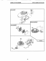
TO REMOVE DRIVE BELT
o)
ID
__PIVOT
_
\
pulley
Belt keeper
\
\
Figure
Housing
hole
8
4. Pivot idler arm assembly to slacken
drive belt, then remove drive belt from
drive pulley, belt keepers and idler arm.
5. Turn lawn mower on its side. Make
sure air filter and carburetor are up.
6. Remove screw securing debris shield.
Note that the debris shield has a tab
which fits into a gap in the housing
(See Figure C).
1. Disconnect spark plug wire from spark
plug and place wire where it cannot
come in contact with plug.
2. Remove screws retaining drive cover
and remove drive cover from lawn
mower housing (See Figure A)o
Crankshaft
Tab
Housing
hole
\
Blade
adapter
(pulley
end)
Hardened
washer
Lawn
mower
housing
Drive
cove r
A
Screw
1
_
_,.
Blade
bolt
_
Figure
Drive belt
15
Lock-washer
Trailing edge
Figure
C
7, Use a wood block between blade and
mower housingto prevent blade from
turning when removing blade bolt,
NOTE: Protectyour hands with gloves
and/or wrap blade with heavy cloth,
8, Remove blade bolt,
9. Remove blade, attaching hardware
(bolt, lock washer and hardenedwasher), blade adapter and debris shield as
one assembly,
10,Remove drive belt from blade adapter
and debris shield; discard old belt.
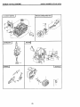
TO REPLACE DRIVE BELT
1. Place new drive belt in the belt retainer
of the debris shield. Be sure to route
belt between belt keepers and through
slot (See Figure D),
Belt
Tab
Belt
Drive
belt
\
Slot
Figure
9. Install new drive belt into idler arm
assembly, then around the drive pulley.
Be sure belt is inside of belt keepers
(See Figure B).
NOTE: Pulling on the drive belt (to install
it on the drive pulley) will cause the other
end of the belt to free itself from the debris
shield retainer and properly seat itself in
groove of pulley end of the blade adapter.
10. Reattach drive cable spring to the idler
arm assembly, then reattach drive
cable to anchor.
11. Reattach drive cover with screws previously removed.
12. Connect spark plug wire to spark plug.
TO ADJUST HANDLE
The handle on your lawn mower has
multiple height positions - adjust to height
that suits you.
1. Remove knob and carriage bolt on left
side of the lower handle,
2, While holding handle assembly, remove knob and carriage bolt from right
side. Align hole in handle with desired
hole in handle bracket, then reassemble bolt and knob and tighten securely.
3. Align left side of handle with same positioning hole as right side and secure
with bott and knob.
Debris
shield
Knob
. _,,,.,,j
Bolt
U}
2. Route the other end of the new drive
belt through hole in housing.
3. Reattach debris shield to housing with
screw previously removed. Be sure tab
of debris shield is in gap of housing.
4. Position blade on the blade adapter
aligning the two (2) holes in the blade
with the raised lugs on the adapter.
5. Be sure the trailing edge of blade (opposite sharp edge) is up toward the
engine (See Figure C).
6, install the blade bolt with the lock
washer and hardened washer into
blade adapter and crankshaft.
7. Use block of wood between blade and
lawn mower housing and tighten the
blade bolt, turning clockwise.
• The recomrnended tightening torque is
35-40 ft. Ibs,
IMPORTANT: Blade bolt is heat treated.
If bolt needs replacing, replace only with
approved bolt shown in the Repair Parts
section of this manual,
8. Return mower to upright position.
Handle
ENGINE
Maintenance, repair, or replacement of the
emission control devices and systems, which
are being done at the customers expense,
may be performed by any non-road engine
repair establishment or individual. Warranty
repairs must be performed by an authorized
engine manufacturer's service outlet.
16
ENGINE SPEED
Your engine speed has been factory set.
Do not attempt to increase engine speed
or it may result in personal injury. If you
believe that engine is running too fast or
too slow, take your mower to a Sears or
other qualified service center for repair
and adjustment.
CARBURETOR
mower to a Sears or other qualified service
center for repair and/or adjustment.
IMPORTANT:
Never tamper with the
engine governor, which is factory set
for proper engine speed. Overspeeding
the engine above the factory high speed
setting can be dangerous. If you think
the engine-governed high speed needs
adjusting, contact a Sears or other
qualified service center, which has proper
equipment and experience to make any
necessary adjustments.
Your carburetor is not adjustable.
If your
engine does not operate properly due to suspected carburetor problems, take your lawn
immediately prepare your lawn mower for
storage at the end of the season or if the
unit will not be used for 30 days or more.
IMPORTANT: When folding the handle for
storage or transportation, be sure to fold it
as shown or you may damage the control
cables.
LAWN MOWER
When lawn mower is to be stored for a
period of time, clean it thoroughly, remove
all dirt, grease, leaves, etc. Store in a
clean, dry area.
1. Clean entire lawn mower (See
"CLEANING" in the Maintenance section of this manual).
2. Lubricate as shown in the Maintenance
section of this manual.
3. Be sure that af! nuts, bolts, screws, and
pins are securely fastened. Inspect
moving parts for damage, breakage
and wear. Replace if necessary°
4. Touch up all rusted or chipped paint
surfaces. Be sure to sand surface
lightly before painting_
HANDLE
Operator presence
control bar
)LD
Upper
Lower
Mowing
position
You can fold your lawn mower handle for
storage.
NOTE: The upper handle has an "antifold" bracket located on the left side of the
handle. This bracket prevents the upper
handle from folding forward, which helps
protect control cable(s) from damage.
1. Loosen the two (2) handle knobs on
sides of the upper handle and allow
handle to fold down to the rear.
2. Remove the two (2) handle knobs and
carriage bolts on sides of the lower
handle and pivot entire handle assembly forward and allow it to rest on
mower.
3_ Reinstall knobs and carriage bolts to
lower handle or handle brackets for
safe keeping.
• When setting up your handle from the
storage position, you must manually
lock lower handle into mowing position.
Bolt
Kn°b X
Handle'
bracket
17
reach the carburetor'. Do not empty the gas
tank and carburetor if using fuel stabilizer.
ENGINE OIL
Drain oil (with engine warm) and replace
with clean engine oil, (See "ENGINE" in
the Maintenance section of this manual).
CYLINDER
1. Remove spark plug,
2, Pour one ounce (29 ml) of oil through
spark plug hole into cylinder,
3. Pull starter handle slowly a few times
to distribute oil.
4. Replace with new spark plug.
OTHER
• Do not store gasoline from one season
to another,
o Replace your gasoline can if your can
starts to rust. Rust and/or dirt in your
gasoline will cause problems.
• If possible, store your unit indoors and
cover it to protect it from dust and dirt.
o Cover your' unit with a suitable protective cover that does not retain moisture,
Do not use plastic, Plastic cannot
breathe, which allows condensation to
form and will cause your unit to rust.
IMPORTANT:
Never cover mower while
engine and exhaust areas are still warm,
_t:_CAUTION: Never store the lawn mower
ENGINE
Maintenance, repair, or replacement of the
emission control devices and systems, which
are being done at the customers expense,
may be performed by any non-road engine
repair establishment or individual, Warranty
repairs must be performed by an authorized
engine manufacturer's service outlet.
FU EL SYSTEM
IMPORTANT:
It is important to prevent
gum deposits from forming in essential
fuel system parts such as carburetor, fuel
filter, fuel hose, or tank during storage.
Also, alcohol blended fuels (called gasohol
or using ethanol or' methanol) can attract
moisture which leads to separation and
formation of acids during storage, Acidic
gas can damage the fuel system of an
engine while in storage,
o Empty the fuel tank by starting the engine and letting it run until the fuel lines
and carburetor are empty,
o Never use engine or carburetor cleaner
products in the fuel tank or permanent
damage may occur.
o Use fresh fuel next season,
NOTE: Fuel stabilizer is an acceptable alternative in minimizing the formation of fuel
gum deposits during storage. Add stabilizer
to gasoline in fuel tank or storage container.
Always follow the mix ratio found on stabilizer
container, Run engine at least 10 minutes
after adding stabilizer to allow the stabilizer to
with gasoline in the tank inside a building
where fumes may reach an open flame
or spark. Allow the engine to cool before
storing in any enclosure,
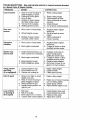
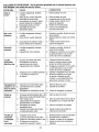
TROUBLESHOOTING
- See appropriate
to a Sears Parts & Repair Center,
CAUSE
PROBLEM
:)oes not start
section in manual unless directed
1. Dirty air filter,
2. Out of fuel,
3. Stale fuel.
4. Water in fuel,
5, Spark plug wire is
disconnected.
6. Bad spark plug,
7. Loose blade or broken
blade adapter.
8, Control bar in released
position.
9. Control bar defective.
10. Fuel valve lever (if so
equipped) in OFF position,
11 .Weak battery (if equipped),
12. Disconnected battery
connector (if equipped),
18
CORRECTION
!, Clean/replace air filter,
2, Fill fuel tank,
3. Empty fuel tank and refill tank
with fresh, clean gasoline,
4, Empty fuel tank and refill tank
with fresh, clean gasoline.
5o Connect wire to plug,
6, Replace spark plug.
7. Tighten blade bolt or
replace blade adapter.
8, Depress control bar to
handle,
9_ Replace control bar.
t0. Turn fuel valve lever
to the ON position,
11. Charge battery.
12, Connect battery to engine.
TROUBLESHOOTING
- See appropriate
to a Sears Parts & Repair Center.
PROBLEM
5.
6.
t,
Worn, bent or loose blade.
2. Wheel heights uneven.
3. Buildup of grass, leaves
and trash under mower.
1. Worn, bent or loose blade.
2.
Starter rope
hard to pull
.
Bent engine crankshaft,
Engine flywheel brake is on
when control bar is released.
2. Bent engine crankshaft.
3. Blade adapter broken.
4. Blade dragging in grass,
............
unless directed
CORRECTION
Rear of mower housing or
blade dragging in grass.
Cutting too much grass.
Dirty air filter.
Buildup of grass, leaves,
and trash under mower.
Too much oil in engine,
Walking speed too fast.
2.
3,
4.
Excessive
vibration
in manual
CAUSE
Loss of power
Poor cut uneven
section
1. Raise cutting height°
Raise cutting height°
3. Clean/replace air filter,
4. Clean underside of mower
housing.
5. Check oil level.
6_ Cut at slower walking speed_
2_
1. Replace blade, Tighten
blade bolt.
2, Set all wheels at same
height.
3. Clean underside of
mower housing,
1. Replace blade. Tighten
blade bolto
2. Contact a Sears or other
qualified service center.
1. Depress control bar to
upper handle before
pulling the starter rope.
2. Contact a Sears or other
qualified service center.
3. Replace blade adapter.
4. Move lawn mower to cut
grass or to hard surface.
= .....
Grass catcher
not filling
(If so equipped)
1. Cutting height too low.
2. Lift on blade worn off.
3. Catcher not venting air.
1. Raise cutting height.
2. Replace blade.
3. Clean grass catcher.
Hard to push
1. Grass is too high or wheel
height is too low.
Rear of mower housing or
blade dragging in grass.
Grass catcher too full.
4. Handle height position not
right for you°
1. Raise cutting height.
24
,
Loss of drive
or slowing of
drive speed
1,
2.
3.
4o
Belt wear°
Belt off of pulley°
Drive cable worn or broken.
"Loose" drive control system.
19
2. Raise rear of mower housing
one (t) setting higher.
3. Empty grass catcher.
4. Adjust handle height to suit.
1.
2.
3.
4.
Check/replace drive belt.
Check/reinstall drive belt,
Replace drive cable.
Adjust drive control.
Garantia ................................................................ 20
Reglas de Seguridad .................................. 20-22
Montaje / Pre-Operaci6n ............................. 23-24
Operaci6n .........................._...................... _...o25-29
Mantenimiento ...........................................
30-33
Programa de Mantenimiento ........................... 31
GARANT[A
Especificaciones del Producto .......................... 22
Servicio y Adjustes ....................................... 33-35
Almacenamiento ............................................ 35-36
Identificaci6n de problemas ........................ 36-37
Partes de repuesto ........,. .......................... 38-47
Servicio Sears .......................................Contratapa
LIMITADA DE DOS AtklOS PARA LA SEGADORA
A MOTOR CRAFTSMAN
Per dos (2) aSos, a partir de la fecha de compra, cuando esta Segadora C_aftsman se mantenga,
lubrique y afine segt3n las instrucciones para fa operaci6n y el mantenimiento en el manual del
due5o, Sears repararA gratis todo defecto en el material y la mane de obra.
Si la Segadora Craftsman se usa para fines comerciates
per noventa (90) dfas a partir de la fecha de compra.
o de arriendo, esta garantfa s61o se aplica
Esta Garantia no cubre:
.
Articulos que se desgastan durante el use normal tales come las cuchillas segadoras rotatorias,
los adaptadores de la cuchitla, las correas, los filtros de aire y las bujias.
•
Reparaciones necesarias debido al abuse o a la negligencia del operador, incluy6ndose a los
cigLieSales doblados y a la falta de mantenimiento del equipo seg[3n las instrucciones que se
inctuyen en el manual del dueP,o.
El servicio de garantia esta disponible al devolver la segadora a motor Craftsman al Centre de
Sewicio Sears mas cercano en los Estados Unidos Esta garantfa se aplica solamente mientras el
producto este en use en los Estados Unidos.,
Esta Garantia le otorga derechos legales especificos,
que varian de estado a estado.
y puede que tambi6n tenga otros derechos
Sears, Roebuck and Co., D/817WA, Hoffman Estates, IL 60179
USA
IMPORTANTE: Esta rnaquina cortadaora es capaz de amputar las manes y los manes y los pies y
de lanzar objetos. Si no se observan las instrucciones de segufidad siguientes se pueden producir
lesiones graves o la muerte.
_Busque
este simbolo que sefiala las precauciones de seguddad de importancia. Quiere
decir - i i iATENCION!!! i iiESTE ALERTOI!!
"
D Ao
SU SEGURIDAD ESTA COMPROMETI
_ADVERTENCIA:
Siempre desconecte el atambre de la bujfa y p6ngalo donde no pueda entrar
en contacto con la bujfa, para evitar el arranque
per accidente, durante la preparaci6n, el trans_te,
el ajuste o cuando se hacen reparaciones,
DVERTENOIA: Los bornes, terminales y
accesorios relatives de la baterfa contienen
plomo o compuestos de ptomo, productos
quimicos conocidos en el Estado de California
come causa de cancer y defectos al nacimiento
u otros dares reproductivoso Lavar las manes
_spu_s
de manipularles,
PRECAUCION: El tubo de escape del motor,
algunos de sus constituyentes y algunos componentes del vehiculo contienen o desprenden
productos quimicos conocidos en et Estado de
California come causa de cancer y defectos al
,_cimiento u otros da_os reproductivos.
PREOAUCI6N.
E1sitenciador y otras piezas
del motor ilegan a sre extremadamente calien-
tes durante la operaci6n y
siguen siendo calientes
despu6s de que el motor
haya parade. Para evitar
quemaduras severas,
permanezca lejos de estas Areas.
I. OPERACION
• Arltes de empezar, debe famUiarizarse completamente con los controles y el use correcto de
la maquina. Para esto, debe leer y comprender
todas fas instrucciones que aparecen en la maquina y en los manuales de operaci6n.
- No ponga las manes o los pies cerca o
debajo de las partes rotatodaso Mant_ngase
siempre lejos de la abertura de la descarga.
• Permita que solamente las personas responsabtes que est6n familiarizadas con las
instrucciones operen la mAquina.
o Despeje el Area de objetostales come piedras,
juguetes, alambres, huesos, palos, etc. que pueden set recogidos y lanzados porlas cuchillaso
o
Aseg_rese que et Area no se hallen personas, antes de segar. Pare la mAquina si
20 alguien entra en el Area°
° No opere la maquina sin zapatos o con sandalias abiertas. PSngase siempre zapatos s61ido&
° No tire de la segadora hacia atrAs a menos
que sea absolutamente necesado.. Mire
siempre hacia abajo y hacia detrAs antes y
mientras que se mueve hacia atrAso
• Nunca dirigir el material descargado hacia
las persona& Evitar descargar material
contra paredes o barreras. El material puede
retornar al operador.. Para la cuchilta cuando
se pasa por superficies de gravao
° No opere la segadora sin tos respectivos
resguardos, las pfacas, et recogedor de
c_sped u otros aditamentos dise ados para
su protecci6n y seguridad.
• Refi#rase alas instrucciones del fabficante
para el funcionamiento e instalaci6n de
accesorios. Use _nicamente accesorios
aprobados pot el fabricante..
o Detenga la cuchilla o las cuchillas cuando cruce
por calzadas, calles o caminos de gravao
, Parar el motor cada vez que se abandona el
aparato, antes de limpiar la segadora o de
remover residuos det tubo.
° Apagar e! motor y esperar hasta que las
cuchillas est_n completamente paradas
antes de remover el receptor de hierb&
• Segar solamente con luz del dfa o con una
buena luz artificial..
° No opere la m_,quina bajo la influencia del
alcohol o de las drogaso
• Nunca opere la maquina cuando la hierba
est_ mojadao Asegurese siempre de tener
buena tracci6n en sus pies; mantenga el
mango firrnemente y camine; nunca corrao
• Desconectar el mecanismo de propulsi6n
aut6noma o el embrague de transmisi6n en
las segadoras que io tienen antes de poner
en marcha el motor.
• Si el equipo empezara a vibrar de una manera
anormal, pare el motor y revise de inmediato
para averiguar la caus& Generalmente la vibraci6n suele indicar que existe alguna averfa°
° Siempre use gafas de seguridad o anteojos con
protecci6n lateral cuando opere la segadora.
II, OPERACION
SOBRE LAS CUESTAS
Los accidentes ocurren con mAs frecuencia en
las cuesta& Estos accidentes ocurren debido a
resbaladas o caidas, las cuales pueden resultar
en graves lesiones. Operar la recortadora en
cuestas requiere mayor concentraci6n_ Si se
siente inseguro en una cuesta, no la recorte.
HACER;
• Puede recortar a trav_s de la superficie de
la cuesta, nunca hacia arriba y hacia abajo.
Proceda con extrema precauci6n cuando
cambie de direcci6n en las cuestas.
° Renueva todos los objetos extrafios, tales
como guijarros, ramas, etco
• Debe prestar atenct6n a hoyos, baches o
protuberanciaso Recuerde que la hierba alta
puede esconder obstAculos.
NO HAOER;
• No recorte cerca de pendientes, zanjas o
terraplene& El operador puede perder la
tracci6n en los pies o el equilibrio.
° No recorte cuestas demasiado inclinadas.
o No recorte en hierba mojada. La reducci6n en la
tracci6n de la pisada puede causar resbalones..
III, NII_IOS
Se pueden producir accidentes trAgicos si el operador no presta atenci6n a la presencia de los
nifio& A menudo, los nifios se sienten atra[dos por
la mAquina y pot la actividad de la siega. Nunca
suponga que los nifios van a permanecer en el
mismo lugar donde los vio por t_ltima vezo
, Mantenga a los nifios afejados del Area de
la siega y bajo et cuidado estricto de otra
persona adulta responsable.
° Est_ alerta y apague la m&quina si hay nifios
que entran al Area°
o Antes y cuando este retrocediendo, mire
hacia arras y hacia abajo para verificar si hay
nifios pequefios_
° Nunca permita que los nifiosoperen la m_quina.
o Tenga un cuidado extra cuando se acerque
a esquinas donde no hay visibilidad, a los
arbustos, _rboles u otros objetos que pueden
intefferir con su I[nea de visi6n.
IV. MANEJO SEGURO
DE GASOLINA
Usar mucha atenci6n cuando se maneja gasolina.. La gasolina es extremamente inflamable y
los vapores son explosives.
° Apagar todos los cigarrillos, cigarros, pipas y
otras fuentes de ignici6no
o Usar solo un contenedor apropiadoo
• Nunca quitar el tap6n de la gasolina o afiadir
carburante con el motor en marcha. Esperar que
el motor se enffie antes de repostar la gasolina.
° Nunca repostarla mAquinaal interior de un localo
• Nunca guardar ta m_quina o el contenedor de
gasolina donde hay una IIama abierta, chispa o
luz piloto como una caldera u otros dispositivos.
° Nunca Ifenar contenedores en un vehiculo, en
un carni6n o caravana con un forro de pl&sticoo
Co!ocar siempre los contenedores en el suelo
tejos de su vehfculo antes de Ilenar..
• Quitar equipos que funcionan con gasoltna
det cami6n o caravana y repostar en el suelo..
Si esto no es posible, repostar dicho equipo
con un contenedor portAtil, mAs bien que con
una tobera de gasolina.
o Mantener la tobera en contacto con el bordo
del dep6sito de carburante o de la apertura
del contenedor siempre hasta terminar el
abastecimiento. No usar un dispositivo de
cierre-apertura de ta tobera.
• Si el carburante cae en la ropa que se Ileva,
cambiArseta inmediatamenteo
° Nunca Ilenar en exceso el dep6sito de
carburante. Colocar et tap6n de la gasolina y
apretar de modo seguro_
V. SERVIClO
° Nunca haga funcionar una m#,quina dentro
de un Area cerradao
• Nunca haga ajustes o reparaciones mientras
el motor est6 en march& Desconecte el cable
de la bujfa, y mant6ngalo a cierta distancia de
6sta para prevenir un arranque accidental.
° Mantenga las tuercas y los pernos, especiatmente los pernos del accesorio de la
cuchilla, apretados y mantenga el equipo en
21 buenas condiciones
,
Los componentes
del receptor de la hierba
van sujetos a desgaste, daS.os y deterioro, que
pueden exporter las partes en movimiento o
permitir que objetos sean disparados. Controtar
frecuentemente y cuando sea necesario sustituir con pattes aconsejadas pot et fabricante_
• Las cuchiltas de la segadora est_n afiladas y
pueden cortaro Cubrir las hojas o Ilevar guantes,
y utilizar precauciones especiales cuando se
efectQa mantenimiento sobre tas mismas.
o No cambie el ajuste del regulador del motor
ni exceda su ve!ocidad.
- Mantener o sustituir las etiquetas de seguridad
e instrucciones, cuando sea necesarioo
Nunca man!pule de forma indebida los
dispositivos de seguridad. Controle regularmente su funcionamiento correcto.
• Mantenga la mAquina libre de hierba, hojas
u otras acumulaciones de desperdicio.
Limpie los derrames de aceite o combustible.
Permita que la m_quina se enfrie antes de
almacenarla.
• Pare e inspeccione el equipo si le pega a un
objeto_ Rep_.relo, si es necesado, antes de
hacerlo arrancaro
• En ningQn caso hay que regular ta altura de
tas ruedas mientras el motor est_ en marcha_
N_mero de Serie:
Fecha de Compra:
Capacidad
y Tipo de Gasolina:
1.0 Cuartos (ReguLar sin Plomo)
de Aceite:
18.50nzas
Tipo de Aceite (API SG-SL):
SAE 30 (Debajo 0°C/32°F)
Bujfa (Abertura:
NGK BPR6ES
.030")
Tolerancia de V&lvula (± 0.004 mm)
Admisi6n:
Torsi6n del Perno de ia Cuchilla:
35-40 ft. Ibs.
o SAE t0W30
0.015 mm; Descarga: 0.020 mm
• El n_mero del nodelo y el de serie se encuentran en la calcomania adjunta a la parte trasera
de la caja de ta segadora_Debe registrar tanto el numero de serie come la fecha de compra y
mantengalos en un lugar seguro para refencia en e! futuro.
Acuerdos
de Protecci6n
para la Reparacibn
Ayuda rdpida por tel_fono - soporte telef6nico por parte de un t6cnico Sears sobre
productos que requieren un arreglo en casa,
y adem_s una programaci6n sobre los a
reglos rods convenientes.
Congratulaciones por su buena compra. Su
nuevo producto Craftsman® estd disefiado
y fabricado para funcionar de modo fiabte por
muchos afios, Pero como todos los productos,
puede necesitar atguna reparaci6n de tanto
en tanto. En este caso tener un Acuerdo de
Protecci6n para ta Reparaci6n puede hacerles
ahorrar dinero y fastidioso
Cuando se ha comprado el Acuerdo, basta con
una Ilamada telef6nica para programar el servicio. Puede Ilamar cuando quiera, dfa y noche o
fijar en linea una cita para obtener el servicio°
Sears tiene mds de 12.000 especialistas
profesionales en la reparaci6n, que tienen
acceso a m&s de 4.5 millones de partes y
accesorios de cat!dad. Este es el tipo de
profesionalidad con que puede contar para
ayudar a alargar la vida del producto que acaba
de comprar, por muchos aP,os. iCompre hoy su
Acuerdo de Protecci6n para la Reparaci6nl
Se aplican algunas limitaciones
y exclusiones. Para conocer los precios y tenet
rods informacibn,
Ilame al 1-800-827-6655.
Compre ahora un Acuerdo de ProtecciSn para
la ReparaciSn y prot#gese de molest!as y gastos inesperados_
Un Acuerdo incluye los puntos siguientes:
= Servicio experto de nuestros 12.000 especialistas profesionales en la reparaci6n.
• Servicio Uimitado sin cargo alguno para
las parses y la mano de obra sobre todas las
reparaciones garantizadas.
= Sustituci6n del producto si su producto
garantizado no puede ser arreglado.
• Descuento de110% sobre el precio corriente del servicio y de las partes relativas al
ser_icio no cubiertas pot el acuerdo; tambi_n
el 10% menos sobre el precio corriente de
un control de mantenimiento preventive.
Servicio de instalaci6n
Sears
Para la instalaciSn profesional Sears de
aparatos de casa, puertas de garaje,
calentadores de agua y otros importantes
articulos para la casa, en U.S.Ao llamar a
1-800-4-MY-HOME®.
22
Estos accesorios estaban disponibles cuando se produjo la segadora. No son facilitados junto al
cortacesped
Tambi6n estdn disponibles en la mayorfa de las tiendas de Sears y en los centros de
servicio_ Algunos de estos accesorios tal vez no se apliquen a su segadora.
RENDIMIENTO
DE LA SEGADORA
A
DESVIADOR
DE RECORTES
PAPA SEGADOPAS
CON DESCARGA
TRASERA
_D
ESTABILI-
E GASOLINA
,,J,,,L,I,,!,H,,,,,I
,g
PARA
SEGADOPAS
CON
DESCARGA
RECOREDOR
TRASEPA
MANTENIMIENTO
,,,,l,,,m H
RECOREDOR
PARA
SEGADOPAS
CON DESCARGA
LATERAL
DE LA SEGADORA
SILENC[ADORES
I,,,ILUUII,,JJ,mH,H,, HI
,I
FILTROS DE AtRE
,,,,,,,,,,,,,
,
,H ,,,I
CUCHILLAS
DECUCHILLA
Lea estas instrucciones y este manual completamente antes de tratar de montar u operar su
segadora nuevao
IMPORTANTE: Este cortac#sped viene SIN
ACEITE O GASOLINA en el motor.
BUJ{AS
II
ADAPTADORES
CORREAS
ENVASES
ZADORES
)
RUEDAS
ACEITE
DEL MOTOR
PARA REMOVER
LA SEGADORA
LA CAJA DE CARTON
DE
1_ Remueva tas partes sueitas que se inctuyen
con la segadora.
2. Corte las dos esquinas de los extremos
de la caja de cart6n y tienda el panel del
extremo piano.
3o Remueva todo el material de empaque, excepto la cuRa entre el mango superior y _1
inferior, y ta cuSa que sujeta la barra de los
control que exige la presencia del operador
junto con el mango superior.
4. Haga rodar la segadora hacia afuera de la
caja de cartSn y revisela cuidadosamente
para verificar si todavfa quedan partes
sueltas adicionales,
Su segadora nueva ha sido montada en la
f&brica con la excepciSn de aquellas partes que
se dejaron sin montar por razones de envio.
Todas las partes como las tuercas, las arandelas, los pernos, etco, que son necesadas para
completar el montaje han sido colocadas en la
bolsa de partes. Para asegurarse que su segadora funcione en forma segura y adecuada,
todas las partes y los articutos de ferreteria que
se monten tienen que ser apretados seguramente_ Use las herramientas correctas, como
sea necesario, para asegurar que se aprieten
adecuadamente.
23
COIViO PREPARAR
SU SEGADORA
PARA DESDOBLAR EL MANGO
IMPORTANTE:
Despliegue et mango con
mucho cuidado para no pellizcar o dafiar los
cables de control,
1. Levante la secci6n del mango inferior hasta
la posici6n de operaci6n y alinee el agujero
en _ste con uno de los agujeros para deterrninar la altura en e! puntal del mango°
2, Inserte el perno del mango a trav_s de 6ste
y del puntal y asegLire!o con la manilla.
3. Repita el procedimiento para el lado
opuesto del mango.
4_ Levante la secci6n del mango superior
hasta la posici6n de operaci6n, remueva la
cuP,a protectora y apriete las manitlas del
mango en forma segura.
5. Remueva el material de empaque de al_ededor de la barra de control.
El mango de la segadora puede ajustarse
seg_Jn le acomode para segar. Refi6rase a
"AJUSTE DEL MANGO" en la secci6n de
Servicio y Ajustes de este manual.
PARA MONTAR EL RECOGEDOR DE
C_SPED
1o Deslizar el saco de la hierba sobre el
armaz6n_ Asegurarse de que el rnango
trasero est6 arriba (el mismo lado que el
mango delantero) y la abrazadera abajoo
2_
Deslice los sujetadores de vinilo sobre el
bastidor,
.....
AVISO', Si los sujetadores de vinilo est&n muy
duros, m6talos en agua caliente por algunos
minutos, Si se moja la boise, d_jela que se
seque antes de usarla.
3. Cerrar la puerta del dep6sito de hierba.
AVISO: Cuando est_ completamente cerreda,
la puerta se cerrar'& con un disparo sobre el
armaz6n y los elementos de fijaci6n en vinilo.
Mango
posterior
,
Barra de control que
\
Mango superior
Mango Inferior
\
LEVANTAR
\
x
\
1
\
Mango
anterior
\
\
para segar
Puerta_
El bastidor
del
recoge_
Pemo
Sujetadores
de vinilo
ManiUa
,_
\
Soporte
de mango
PARA INSTALAR LOS ACCESORIOS
Su segadora rue enviada lista para usarse
como una acolchadora de capa vegetal. Para
convertirla de modo que pueda ensacar o
descarga, refi_rase a "PARA CONVERIR LA
SEGADORA" en la secci6n de Operaci6n de
este manual°
24
FAMILIARICESE
CON SU SEGADORA
LEA ESTE MANUAL DEL DUENOY LAS REGLAS DE SEGURIDAD ANTES DE OPARAR SU
SEGADORAr
Compare las ilustraciones con su segadora para familiarizarse con la ubicaci6n de
los diversos controles y ajustes. Guarde este manual para referencia en el futuro
Estos simbolos pueden apareser
producto.
Aprenda y comprenda
ATTENCI6N O
ADVERTENOIA
:
MOTOR
MOTOR
ENCEND_DO APAGADO
, ,,,,,
........
,
sobre su segadora
sus significados°
R_PIDO
LENTO
o en la literatura
con el
COMACEtTE
PELIGRO, GUARDE LAS
BUSTIBLE
MANOS Y LOS PIES LEJOS
ESTRANGU
LACld)N
.....
proporcionada
...............
I
,
iii1,,i ,i,1,11
,.
Barra de control que exige la
presencia del operador
- Palanca de control de ta impulsiSn
CordSn
arrancador
Manilla del mango
Tapa del deposito
de ta gasolina
V_lvuta del
combustible
Recogedor
de c_sped
Filtro de aire
Mango del
_u_ador
de un
duelpunto
Tapa del deposito
de aciete del motor
con varilla
indicadora de nivel
Silenciador
Puerta de la acolchadora
Caja
IMPORTANTE:
.............. ,,11
Este cortac6sped
viene SIN ACEITE O GASOLINA en motor.
, i
CUMPLE CON
Las segadoras
los est_ndares
Product Safety
LOS REQUISlTOS DE SEGURIDAD DE LA CPSC
a motor, que se conducen desde ta parte de atr&s, rotatorias, Sears, cumplen con
de seguridad de! American National Standards Institute y de la U.S. Consumer
Commission,
La cuchilla gira cuando el motor estA funcionando.
,,, ,, .,,,,,,,,,
Barra de control que exige la presencia del
operador - tiene que sujetarse abajo, junto
con el mango, para hacer arrancar e! motor
Su_ltela para parar el motor.
Palanca de control de la impulsion - se usa
para enganchar la segadora para movimiento
hacia adelante impulsada a motor
Cord6n arrancador - se usa para hacer arrancar el motor.
Puerta de la acoichadora
- permite la conversiSn para la operaciSn de descarga o ensacado.
Mango del ajustador de un duel punto- se usa
para ajustar la altura de corte de la segadora.
25
La operaciOn de cualquier
segadora puede hacer que
salten objetos extraOos dentro de
sus ojos, fo que puede producir
daOos graves en _sto& Siempre
use anteojos de seguridad o protecciOn para
los ojos m entras opere su segadora o cuando ....
haga ajustes o reparaciones. Recomendamos
gafas o una mascara de seguridad de vision
amplia de seguridad usada sobre las galas.
COMO USAR SU SEGADORA
VELOClDAD DEL MOTOR
La velocidad del motor se estableciO en la f&bdca para un rendimiento 5ptimoo La ve!ocidad
no se puede ajustaro
CONTROL DE ZONA DEL MOTOR
PRECAUCION. '_Las regutaciones federales
exigen que se instale un control para el motor
en esta segadora para reducir a un mfnimo el
riesgo de lesionarse debido al contacto con la
cuchilla. Pot ning_n motivo trate de eliminar
la funciOn del control del operador_ La cuchilla
gira cuando el motor est#, funcionando.
o Su segadom viene equipada con una barra
de controles que exigen la presencia del
operador, Io que raquiere que et operador
est_ detr&s del mango de la segadora para
hacerla arrancar y operarla.
CONTROL DE LA IMPULSION
o La autopropulsiOn se controla manteniendo
la palanca de mando operador presente
abajo hacia el mango y tirando la palanca de
accionamiento atr_s hacia el mango. Cuanto
m&s lejos se tira la palanca hacia el mango,
m,_s r_pida ira la unidad_
- E! movimiento hacia adelante se detiene
cuando sea la palanca de mando operador
presente o la palanca de accionamiento se
sueltan. Para detener el movimiento hacia
adelante sin apagar el motor, soltar solo
la palanca de accionamiento. Mantener la
palanca de mando operador presente abajo
contra el mango para continuar a cortar sin
autopropulsiOn.
AVISO; Si despuOs haber desenganchado
de la palanca de control, la segadora no roda
hacia atrAs, empuje la segadora un poco hacia
adelante para desenganchar las ruedas de la
impulsiOn_
, Para mantener el mando conectado cuando
se da la vuelta a una esquina, empujar el
mango para levantar las ruedas delantems
del terreno mientras se gira la cortadora.
Barra de control que
PARA
BorOn ajuste
(en laparte
trasera)
AJUSTE DEL MANDO
Ocasionalrnente, el sistema de mando puede
"aflojarse", provocando una disminuciOn de la
velocidad. Hay un botOn en la parte trasera de
la sede del mando para apretar la tension del
cable. Proceder de ta siguiente manera:
1. Apagar la motor y desconectar el cable de
bujia de la bujf&
2_ Tirar el botOn en la parte inferior del mando
de transmisiOn, luego empujarlo otra vezo
3. Opere la segadora para versi la velocidad del mecanismo ha aumentado. Si no
hay aumento, significa que es necesario
sustituir la correa de transmisiOn.
PARA AJUSTAR LA ALTURA DE CORTE
Las dos ruedas delanteras se ajustan a traves
de una t_nica palanca en la rueda delantera
izquierda. Asimismo, tas dos ruedas traseras
se ajustan a travOs de una Qnica palanca en la
rueda trasera izquierd&
•
Tire de la palanca de ajustes hacia la rued& Levante la segadora, mueva la palanca hasta delante a la posiciOn deseada. Pare bajar la segadora, mueva la palanca hacia la retaguardi&
Asegurarse de que las dos ruedas delanteras y
traseras est_n reguladas a la misma altura.
ATR,_S
PARA
BAJAR
PALANCA
HACIA
EL CORTAC_:SPED
PALANCA HACIA ADELANTE PARA
LEVANTAR EL CORTACESPED
PARA CONVERTIR LA SEGADORA
Su segadora fue enviada lista para usarse
como acolchadora de capa vegetal Para convertirla a una operaciOn de ensacado posterior
o de descargar lateral:
SEGADORAS CON DESCARGATRASERA
-
Quitar el pomo que fija la puerta del acabador a! bastidor del cortac_sped.
• Abdr la puerta del acabador e int_oducir
las leng_etas del tubo de descarga en la
apertura de la brida de la articulaciOn y
colocar la parte trasera del tubo sobre el
pasador roscado.
LengOetas del tubo de descarga
Dresenoladel operador
_,
"_
Control
la impulsiOr
_J
ENGANCHAR EL
CONTROL DE LA
CONTROL DE LA
IMPULSION
IMPULSION
DESENGANCHADO
26Soporte
de
Puerta
• Fijar la parte trasera del canal de descarga al
bastidor del cortac_sped a trav_s det pomo,
o Colocar el mango trasero del dep6sito de
hierba en la alzapdma del mango inferior del
cortac_sped como mostrado,
o A_zar la puerta redonda del canal de eyecci6n y colocar el dep6sito de hierba en el
canal de eyecci6n,,
AVISO: Asegurarse de que la puerta redonda
del canal de eyecci6n se apoye en el dep6sJto
de hierba como mostrado.
• Ahora el cortac_sped est_ listo para la operaci6n de ensacado traseroo
o Para convertir en la operaci6n de acabado,
quitar el dep6sito de hierba y el canal de
eyecci6n, Fijar la puerta del acabador al
bastidor del cortac_sped a trav6s del pomo.
o Para convertir en la operaci6n de descarga,
quitar et dep6sito de hierba y el canal de
eyecci6n. Instalar el deflector de descarga
lateral y fijarlo al bastidor del cortacesped a
trav6s del pomo.
• Fijar la parte trasera del deflector de descarga lateral al bastidor del cortac_sped a
trav6s del pomo.
Ahora el cortac6sped estA listo para fa operaci6n de descarg&
° Para convertir a ta operaci6n de acabado,
hay que quitar el deflector de descarga lateral y fijar la puerta del acabador al bastidor
det cortac6sped a trav6s del pomo.
° Para convertir en la operaci6n de ensacado
trasero, hay que quitar el deflector de descarga lateral; instalar el canal de eyecci6n y el
dep6sito de hierba y fijar el canal de descarga
al bastidor del cortac6sped a trav6s del pomo..
Puerta de la
acolchadora
Manilta
Pasador
roscado
Mango posterior
Barra transversal
det mango infedor
El recogedor
c6sped
Desviador de'
ta descarga
PASOS SIMPLES DE RECORDAR
CUANDO CONVIERTA SU SEGADORA
PARA ACOLCHAMIENTO redonda
t.
Canal
inclinado de
la descarga
El dep6sito de hierba, el canal de eyecci6n
y el deflector de descarga lateral quitados.
2o La puerta deI acabador fijada al bastidor del
cortac_sped a trav6s del pomo°
PARA ENSACAMIENTO TRASERO -
Mani!la
1,, Deflector de descarga lateral quitado.
2. El dep6sito de hierba y el canal de eyecci6n
instalados con el canal de eyecci6n fijado al
bastidor del cortac_sped a trav_s del pomo,,
& La puerta redonda del canal de descarga
apoyada sobre la parte superior del
dep6sito de hierba.
PARA DESCARGA LATERAL-
Pasador
rosoado
Puerta de la acotchadora
SEGADORAS
CON DESCARGA
1.
El dep6sito de hierba y el canal de eyecci6n
quitados,
2. El deflector de descarga lateral instalados y
fijados al bastidor del cortac6sped a trav_s
del pomo.
PRECAUCI6N;
No haga funcionar su segadora sin la puerta trasera se cerr6, desviador de
ta descarga instalada, o sin el canal inclinado
de la descarga o et recogedor c6sped aprobados en su lugar,, Nunca trate de operar la segadora cuando se ha removido a puerta trasera o
puerta redonda cuando est,_ un poco abierta.
LATERAL
• Hay que quitar el dep6sito de hierba y el
canal de eyecci6n,
° Abrir la puerta de la puerta del acabador e
instalar la parte delantera del deflector de
descarga lateral debajo la puerta y colocar el
parte trasero en la esp_rrago fileteado
27
PARA VACIAR EL RECOGEDOR DE ClaSPED
1. Abierto la puerta redonda del canal inclinado de la descarga para mover la cuerda
del arrancador hacia fuera y lejos des de el
recogedor de c_sped.
1. Aseg0rese que la segadora est6 nivelada.
2_ Remueva la varila medidora de aceite del
tubo de desarga de aceite.
3. Usted recibe un envase de aceite con ta
unidad. Vierta lentamente el envase ente[o
de aceite en el tubo de relleno del motor.
4. Inserte y apriete la vari!la medidora de
aceite.
IMPORTANTE'.
. Revise el nivel del aceite antes de cada uso
Agregue aceite si es necesado. Llene hasta la
Ifnea de Ileno en la varilla medidora de nivelo
° Cambie el aceite despu6s de 25 betas de
operaci6n o una vez pot temporada. Puede
necesitar cambiar el aceite m&s a menudo
cuando las condiciones son polvorosas o sucias, Vea "PARA CAMBIAR EL ACEITE DEL
MOTOR" en la seccion de Mantenimiento de
este manual.
\
\
Mango
ABIERTO
redonda
AGREGUE GASOLINA
o Llene el estanque de combustible hasta
la parte inferior del cuello de r elleno de!
estanque de gasolina. No Io Ilene demasiado.
Use gasolina regular, sin plomo, nueva y limpia con el rninimo de 87 octanoso No mezcle
el aceite con la gasolina_ Para asegurar
que la gasolina utilizada sea fresca compre
estanques los cuales puedan ser utilizados
durante los primeros 30 dfas.
,4_PRECAUCION: Limpie el aceite o el
combustible derramado. No almacene, derrame
o use gasolina cerca de una llama expuesta.
,_kPREOAUCI6N:
Los combustibles mezclados
Cuerda del
arrancador
2.
Remueva el recogedor de c6sped, con los
recortes, de la segadora usando tanto el
mango anterior como 61 mango posterior.
3, Vac[e los recortes de el recogedor de
c6sped usando tanto et mango posterior
como 61correa. El peso de la hierba abrir_.
la puerta.
4_ Cerrar fuerte la puerta en el armaz6n antes
de instalar de dep6sito de hierba en el
cor tacesped.
AViSO: No arrastre la bolsa cuando ta vacie;
se producir& un desgaste innecesario_
con alcohol (conocidos como gasoho!, o el uso
de etanol o metanol) pueden atraer la humedad,
la que conduce a la separaci6n y formaci6n de
&cidos durante el almacenamiento. La gasolina
acidica puede daSar et sistema del combustible
de un motor durante el almacenamiento.
Para
evitar los problemas con el motor, se debe vaciar
el sistema del combustible antes de guardarlo por
un periodo de 30 dias o m&s. Vacie el estanque
del combustible, haga arrancar el motor y h_galo
funcionar hasta que las Ifneas del combustible y el
carburador queden vac[os° La pr6xima temporada
use combustible nuevo,.Vea las lnstrucciones Para
Mango
posterior
Correa
Mango
anterior
El Almacenamiento para m&s informaci6no Nunca
use productos de limpieza pare el motor o para el
carburador en el estanque de! combustible pues
se pueden producir daRos permanentes.
Tapa del deposito
de aceite
con
vadlta
de
ntvel
Puerta
ANTES
MOTOR
DE HACER
ARRANCAR
EL
AGREGUE ACEITE
Su segadora fue enviada sin aceite en el motor:
Para el tipo y el grado del aceite a utilizar, yea
el "MOTOR" en la secci6n del Mantenimiento de
este manual.
_,PRECAUOI6N:
NO sobrellene el motor con
aceite, o fumar_ pesa demante del silenciador
cuando lo valla a arrancaro
Marca
superior
28
Marca
inferior
Tapa del
rellenador
de gasolina
PARA PARAR EL MOTOR
• Para parar el motor y si no intenta poneflo en
marcha de nuevo, alivie la barra de control
que exige la presencia del operador. Espere
hasta que la cuchilla y todas las piezas m6 viles se hallan parado y mueva la v_lvula del
combustible a la posicion APAGADO (OFF),
PARA HACER ARRANCAR
EL MOTOR
AVISO: Debido alas capas protectoras det motor, una cantidad pequefia de humo puede estar presente durante el uso iniciat del producto
y se debe considerar normal,
1. Asegurase que v&lvula del combustible est_
en la posici6n ON
2. Mueva la palanca de ta estrangulaci6n a ta
posici6n de ON (1"_,1).
3, Sujete la barra de controles que exigen la
presencia del operador abajo en el mango
y tire el mango del arrancador r_pidamente.
No permita que el cord6n arrancador se
devuelva abruptamente.
AVlSO: La palanca de la estrangutaci6n
comienza a moverse autom_.ticamente a la
posici6n de APAGADO (OFF) cuando ia barra
del control de la presencia del operador se
mantiene hacia el mango.
APAGADO
Palanca de la
ulaci6n
V_lvula del combustible
ONSEJOS
PARA SEGAR
RECAUCION: No utitizar dispositivos anti °
paja de la hoja en la segadora ya que estos
accesorios son peligrosos, pueden dafiar su
segadora y anular su garantfa.
• Bajo ciertas condiciones, tal como c_sped
muy alto, puede ser necesario el etevar la
altura del corte para reducir el esfuerzo
necesario para empujar la segadora y para
evitar sobrecargar el motor, dejando montones de recortes de cesped. Puede que sea
necesario reducir ta velocidad del recorrido
y/o haga funcionar la segadora sobre el Area
por segunda vez.
° Para un corte muy pesado, reduzca el ancho del
cortepasandoparcialmenteporencimadeflugar
anteriormente cortado y siegue lentamente.
• Para un mejor ensacado del c6sped y para la
mayoria de las condiciones de corte, la velocidad del motor debe ajustarse a la posici6n
de Rb,PIDO,
= Los poros en los recogedores de cesped de
tela pueden Ilenarse con mugre y polvo con
el uso y los recogedores recaudar,_n menos
c_sped. Para evitar #ste, rode el recogedor
con ta manguera de agua, regularmente, y
d_jelo secarse antes de usarlo
o Mantenga la parte superior del motor, alrededor del arrancador, despejada y sin recortes
de c6sped y paja. Esto ayudar_ el flujo del
aire del motor y extender& su duraci6no
CONSEJOS
PARA SEGARY
ACOLCHAR
IMPORTANTE: Para obtener el mejor
rendimiento mantenga ta caja de la segadora
sin acumulacion de cesped y basura° Vea
"LIMPIEZA" en la seccion de Mantenimento de
este manual.
• La cuchilla acolchadora especial va a volver a
cortar los recortes de c_sped muchas veces, y
los reduce en tamafio, de modo que si se caen
en el c_sped se van a dispesar entre 6ste y no
se van a notar. Tambi6n, el c_sped acolchado
se va a deshacer r_pidamente entregando
substancias nutritivas para el c6sped. Siempre
acolche con la velocidad del motor (cuchilla)
mAs alta, pues as[ se obtendr_, la mejor acci6n
de recorte de las cuchillae.
• Evite cortar el c_sped cuando est_ mojado.
El c_sped mojado tiende a formar montones
e interfiere con la acci6n de acolchado
La mejor hora para segar el c_sped es
temprano en ta tarde A esa hora este se ha
secado y el _rea reci6n cortada no quedar_
expuesta al sol directo.
° Para obtener los mejores resultados, ajuste
ia altura det corte de la segadora de modo
que _sta corte sotamente el tercio superior
de las hojas de c_sped_ En el caso de que el
c_sped haya crecido demasiado, puede ser
necesario el elevar la altura del corte para
reducir e! esfuerzo necesario para empujar la
segadora y para evitar sobrecargar el motor,
dejando montones de recortes de c_spedr
Para un c_sped muy pesado, reduzca el ancho del corte pasando por encima del lugar
anteriormente cortado y siegue lentamente,
1/3
L# JR=II_V_
•
YlI}I I\I
o Ciertos tipos de c6sped y sus condiciones
pueden exigir que un _rea tenga que ser
acolchada por segunda vez para esconder
completamente los recortes. Cuando se haga
el segundo corte, siegue atravesado (en forma
perpendicular) a la pasada del primer corte,
• Cambie su patr6n de corte de semana a
semanar Siegue de norte a sur una semana
y luego cambie de este a oeste la pr6xima
semana. Esto evitar_, que el c6sped se
29 enrede y cambie de direcci6n.
PROaRAMA
MANTENIMIINTO
Revtser si hay SuJetadores
ANTES DESPUES
....................
DE CADA DE CADA
use
......
Sueltos
1L_mptar#nspecclonaret Recogedar de Cesped
] Controlar los Nauru&rices
_] Centre arlas Ruedas Motttcas
use
v'
v'
v'
v'
J'Umpiar la Segadera ....
_)l Limpiar debajo la Cubierta
de }aTransmtsi6n
v'
..............
v'
*'*
ANTES DEL
ALMACENAMIENTO
"'*
_I Reviser las Cerreas y las Paleas tmpulsadas"l Reviser I Afitar / Cambfar la Cuchll_a
j Lubricacl6n
Limpiar ! Recargar la Baterfa ""
•Reviser el hive! del Acelte
_J Cambiar
el Acelte
del motor
_)J Umptar el Flltre de Alto
r I lnspecc_onarel Stienclader
_1Cambiar
la Bujfa
I Cambtar el Cartucho de Papal del Fittre de Afro
Vaciar el slstema dat carburante
o aSadir un estabtllzador de catburante.
* (s_vieneequIpado)
1 - Gambler m&s a menude cuando se opera bajo catga pesada o an ambtentes conattas temperatures,
** Segaderas can Arranque El_ctrlco 2 - Dar aervtclo m_s a menudo
cuando ae opera an condiciones sucias o polvorosa&
*** Segadorascan Poder Pmpuiaor 3 - Cambie las eu;hiilasm_s e menudocuando steguean terrano aranoso,
**** Uttlb:ar una rasqueta pare llmplat
debejo de la cublerte dat Cortar_sped
4 -Cargar per 48 horas al fin de Is ternporada,
5 - Y deapu_a de 5 bores de functonamiento,
TABLA DE LUBRICACION
RECOMENDACIONES
GENERALES
La garantfa de esta segadora no cubre ios
art{culos que han estado sujetos al abuse o a
ta negfigencia del operadoro Para recibir rode
el valor de la garantfa, el operador tiene que
mantener ta segadora segt]n las instrucciones
descritas en este manual.
(_) Aceite
del motor
Hay algunos ajustes que se tienen que hacer
en forma periSdica para poder mantener su
unidad adecuadamenteo
chadora
AI menos una vez cada estaci6n comprobar
si es necesario efectuar los ajustes descritos
en fas secciones de Servicio y Ajustes de este
manual.
(_) Bisagra de
puerta traser
o Una vez at aSo, cambie la bujia, limpie o
cambie el elernento del filtro de aire y revise
si la cuchilla est_ desgastad& Una bujia
nueva y un elemento del fittro de aire limpio/
nuevo aseguran la rnezcla de aire-combustibie adecuada y ayudan a qua su motor
funcione meier y que dure m_s_
o Siga el programa de mantenimiento en este
manual..
Ctavija
de montaje
de! puntal
del mango
(_ Rocie el lubricante
(_) Vea "MOTOR" en la seccion de Mantenimiento
ANTES DE CADA use
• Revise ef nivel de! aceite del motor°
o Revise si hay sujetadores sueltOSr.
IMPORTANTE: No aceite o engrase los rodamientos de la rueda de plastico. Los lubricantes
viscosos atearan polvo y mugre, fo acortara la
duracion de los rodamientos autolubricantes. Si
cree que tienen que lubricarse, use Iosamente
un lubricante tipo crafito, de polvo seco, en
forma moderadao
LUBRICAClON
Mantenga la unidad bien lubricada
(vea ta 'q'ABLA DE LUBRICACION")o
30
SEGADORA
Siempre observe las reglas de seguridad cuando haga el mantenimiento.
LLANTAS
° Mantenga las llantas sin gasolina, aceite o
substancias qufmicas para control de insectos que pueden daSar la goma,
o Evite Ios tocones, las piedras, las grietas profundas, los objetos afilados y otros peligros
que pueden da5ar alas Ilantaso
RUEDAS DE IMPULSI6N
Revise las ruedas de impulsiSn traseras cada
vez antes de segar, para asegurarse de que se
mueven libremente. Si las ruedas no giran Ii_
bremente quiere decir que hay basura, recortes
de c_sped, etc. dentro del Area de las ruedas
de impulsi6n y de la cubierta contra el polvo y
tienen que limpiarse para liberarlas.
CUlDADO DE LA CUCHILLA
Para obtener los mejores resultados, la cuchitla
de la segadora tienen que mantenerse afilada.,
Cambie la cuchilla doblada o da5ada.
PARA REMOVER LA CUCHILLA
1. Desconecte el alambre de ta bujiay p6ngalo en
donde no pueda entrar en contacto con _sta.
2. Haga descansar la segadora en su lado.
Aseg[)rese que el filtro de aire y que el
carburador queden mirando hacia arribao
& Use un bloque de madera entre la cuchilla
y la caja de la segadora para evitar que la
cuchilla gire cuando se le quite el perno,,
AVlSO; Proteja sus manos con guantes y/o
envuelva la cuchilla con una tela grues&
4, Remueva el perno de la cuchilla gir_ndolo
en el sentido contrario en que giran las
manillas del reloj,
5. Remueva la cuchilla y los articulos de ferreteria adjuntadores (el perno, la arandeta
de seguridad y la arandela endurecida).
PARA CAMBIAR LA CUCHtLLA
1.
Ponga Ia cuchilla en el adaptador de #sta
alineando los dos (2) agujeros en la cuchilla
con las salientes elevadas en el adaptador.
2, Aseg_rese de que el borde de salida de
la cuchilla (opuesto al borde affiado) est6
hacia arriba hacia el motor,
3. Instale el perno de }a cuchitla con la arandela de seguridad y la arandela endurecida
en el adaptador de la cuchilla y el ciguefiaL
4 Use un bloque de madera entre la cuchilia
y la caja de la segadora y apriete el perno
de la cuchilla gir&ndoto en el senticlo en que
giran las manillas del reloj.
• La torsiSn para apretar recomendada es de
35 - 40 pies libra&
IMPORTANTE: El perno de la cuchilla es
tratado a calo. Si es necesario sustituir los
pernos, sustituidos sSIo con pernos aprobados
mostrados en la secci6n Partes de Reparaci6n
de este manual,
PARA AFILAR LA CUCHILLA
AVlSO: No recomendamos et afitar la cuchitla
- pero si Io hace, asegurese de que quede
balanceada,, Se tiene que tener cuidado de
mantenerla balanceada, Una cuchilla que no
est#, balanceada va a producir eventualmente
dafio en ta segadora o en el motor,,
Adaptador Borde de ,f_
__
de }a cuchifla
"_::,
Arandela
de se-
endurecida
Perno de
la cuchilia
-
La cuchilla puede afilarse con una lima o en
una rueda rectificador& No trate de afilarla
mientras se encuentra en la segadora.
o Para revisar el balance de la cuchilla, clave un
clavo en una viga o en la pared., Deje airededor
de una pulgada de un clavo recto expuesto_
Ponga et agujero central de la cuchilia sobre la
cabeza del clavo° Si la cuchilla est,, balanceada
debe permanecer en la posici6n horizontal° Si
cuatquiera de los extremos de la cuchilla se
mueve hacia abajo, afile el extremo pesado
hasta que 6sta quede balanceada,
RECOGEDOR DE CESPED
° El recogedor de c_sped puede ser rociado
con el agua de la manguera pero tiene que
estar seco cuando se vaya a usar.
o Revise su recogedor de c_sped a menudo
para verificar si est_ dafiado o deteriorado.
Se va a desgastar con el uso normal.. Si se
necesita cambiar el recogedor, c&mbieio
solamente por uno que sea aprobado por el
fabricante. D6 el n_Jmero del modelo de la
segadora cuando Io ordene,
CAJA DE ENGRANAJES
• Para mantener
el sistema de impulsi6n
funcionando en forma adecuada, la caja de
engranajes y el _rea alrededor de la imputsi6n
tienen que mantenerse limpias y sin acumulaci6n de basura. Limpie debajo de la eubierta
de la impulsi6n dos veces por temporada..
o La caja de engranajes se Ilena con lubricante
hasta el nivel adecuado en ta f#.brica. La
_)nica vez que el tubricante necesita atenci6n
es cuando se le ha prestado servicio a la
caja de engranajes.
o Si se necesita lubricante, use solamente
Grasa Texaco Starplex Premium 1, Parte No.
750369. No use substitutos.
MOTOR
El mantenimiento, la reparaciSn, o el reemplazo
de cualquier dispositivos o sistemas del control
de la emisi6n, los cuales sean hechos al costo
del cliente, pueden ser realizados por cualquier
individuo o establecimiento de reparaci6n de
motor. Los reparos que caen bajo garantia
deben set realizados por un establecimiento de
31 servicio de reparaci6n de motor autorizado.,
LUBRICACi6N
Use solamente aceite de detergente de alta calldad clasificado con la clasificaci6n SG-SL de servicio APIo Seleccione la calidad de viscosidad SAE
segUn su temperatura de operaci6n esperadao
CAUDADES
"C
-30
-20
-10
7
Continue agregando cantidades pequeas
de aceite y vuelva a inspeccionar la varilla
medidora hasta que lea Ileno (FULL). NO
sobrellene el motor con aceite, o fumar_.
cuando Io valla a ar'rancar.
8,_ Aseg0rese de apretar la varilla medidora
del aceite antes de arrancar el motor.
9_ Vuelva a conectar el alambre de la bujfa a
_sta.
FILTRO DE AIRE
Su motor puede sufrir avedas y funcionar de
manera incorrecta con un filtro del aire sucio.
Sustituir el papel del cartucho una vez af aSo o
tras 100 horas de funcionamiento, m_s a menudo si se utiliza en condiciones de suciedad y
polvo particulares. No lave el filtro de aire.
PARA LIMPtAR EL FtLTRO DE AtRE
1. Remueva la cubierta.
2. Cuidadosamente, remueva el cartucho.
3. Limpielo golpedndolo suavemente en una
superficie plana. Si est_ rnuy sucio cambie
el cartucho.
_,PRECAUCI6N:
Los sotventes de petr61eo,
tales como el keroseno, no se deben usar para
limpiar' el cartuchoo Pueden producir el deterioro
de 6ste. No aceite el cartucho. No use aire a
presi6n para lirnpiarlo o secarlo.
4. Instale el cartucho, luego vuelva a poner la
cubiertao
DE VISCOStDAD DE 8AE
0
10
20
30
40
GAMA DE TEMPERATURA ANI_ICIPADA ANTES D_'L PROXtMO CAMBIO O_ AC EtTE
AVISO: Los aceites de multiviscosidad (5W30,
10W30, etco) mejoran el arranque en ciima fifo,
y revise el nivel del aceite del motor menudo,
para evitar un posible daSo en el motor, debido
a que no tiene suficiente aceite.
Gamble el aceite despu_s de 25 heras de
operaci6n o por Io menos una vez al aSo si la
segadora se utiliza menos 25 horas el aP,oo
Revise el nivel del aceite del c_rter antes de
arrancar el motor y despu_s de cada cinco (5)
horas de uso continuado, Apriete el tap6n del
aceite en forma segura cada vez que revise el
nivel del aceite°
PARA CAMBIAR EL ACEITE DEL MOTOR
AVISO: Antes de inclinar la segadora para drenar el aceite, drene el tanque de combustible
haciendo correr el motor' hasta que el tanque
est_ vacio.
1. Desconecte el alambre de la bujia y
p6ngalo de modo que no pueda entrar en
contacto con 6sta.
2. Remueva la tapa del dep6sito del aceite;
d_jela a un lado en una superficie timpia.
3. Incline la cortadora de c_sped por este
costado tal como se muestra y purgue el
aceite en un recipiente id6neo. Mueva la
segadora de atr_s para adelante para remover todo el aceite que se haya quedado
atrapado dentro del motor.
Cartucho
Orejas
Tapa det
_
\ \
Marca
inferior
Limpie todo el aceite derramado en la segadora yen el lado del motor.
5. Rellene el motor con aceite. Vierta lentarnente
el aceite en e! tubo de relleno del motor.
6o Permita que el aceite se asiente. Use un
medidor en la tapaivarilla indicadora del
nivel para relleno del aceite para revisar el
nivel. Inserte la varilla indicadora de nivel
en el tubo, y haga descansar la tapa del
dep6sito para relleno del aceite en el tubo
a! leer las medidas. No enrosque el tap6n
cuando este tomando una lectura.
de aire
SILENCIADOR
Inspeccione y cambie el silenciador si est,. corrofdo puede producir un peligro de incendio y!o daSo.
BUJiA
Cambie e! bujia al comienzo de cada tempo*
rada de siega o despu_s de cada 100 horas
de operaci6n, 1o que suceda primero. El tipo de
bujia y el ajuste de ta abertura aparecen en "ESPECIFICACIONES
DEL PRODUCTO" secci6n
de este manual
deposito de
aceite con
varillade
Cubierta
del filtro
LIMPIEZA
IMPORTANTE: Para obtener el mejor rendimineto,
mantenga la caja de ta segadora sin acumulacion
de cesped y basura. Limpie la parte de abajo de
su segadora despues de cada usoo
_PREOAUOI6N:
Desconecte el alambre de
4_
la bujia y p6ngalo en donde no pueda entrar en
contacto con 6sta,
32
o Haga descansar
la segadora en su lado.
Asegurese que el filtro de aire y que el carburador queden mirando hacia arriba. Limpie la
parte inferior' de su segadora rasp_ndola pare
remover la acumulaci6n de c6sped y basura.
o
O
Limpie el motor a menudo para evitar que
se acumule la basura.. Un motor tapado funciona m_s caliente y se acorta su duraci6n.
Mantenga las superficies putidas y las ruedas sin gasolina, aceite, etc.
No recomendamos el uso de una manguera
de jardfn para timpiar la segadora a menos
que el sistema el_ctrico, el silenciador, el
filtro de aire y el carburador est#n tapados
para evitar que les entre el agua.; El agua en
el motor puede acortar ta durac_on de _ste..
,&ADVERTENClA:
Para evitar iesidnes serias,
antes de dar calquier servico o de hacer ajustes:
1o Suelte la barra de control y pare el motor.,
2o Aseg_3rese que la cuchiila y que todastas partes
movibtes se hayan detenido completamente.
3. Desconecte el alambre de la bujia y p6ngato en
donde no pueda entrar en contacto con _st&
SEGADORA
PARA AJUSTAR LA ALTURA DE CORTE
Vea "PARA AJUSTAR LA ALTURA DE CORTE"
en la secci6n de Operaci6n de este manual.
DESVlADOR TRASERO
Se proporciona un desviador trasero, adjunto
entre las ruedas traseras de su segadora, para
reducir a un mfnimo la posibilidad que objetos
sean lanzados hacia afuera de la parte trasera
de la segadora, en la posici6n en donde se
encuentra el operador. Si se daRa el desviador
debe cambiarse,
PARA REMOVER LA CORREA DE IMPULSIL3N
1. Desconecte el alambre de ta bujia y p6ngalo en donde no pueda entrar en contacto
con 6sta..
2. Quitar los tornillos que sujetan la tapa del
mando y quitar la tapa del mando de! bastidor del cortac_sped (Vea la Figure A).
LIMPIE DEBAJO DE LA CUBIERTA DE LA
IMPULSION
Limpie debajo de fa cubierta de la impulsi6n
por Io menos dos veces cada temporad&
Raspe debajo de ta cubierta con un cuchillo
para masilla o con una herramienta parecida,
para remover toda acumulaci6n de c6sped o
basura en la parte inferior de la cubierta de ta
impulsi6n_
Cable de mando ancla
Conjunto palanca
de transmisi6n
/
de
mando
Dispositivo
de fijaci6n
Correa de
rnando
Orificio
en el
bastidor
\
\
Figure
B
4.
Empernar el conjunto palanca de transmisi6n para aflojar la correa de mando, luego
quitar la correa de mando de la polea de
mando, los dispositivos de fijaci6n de la correa y la palanca de transmisi6n.
5_ Haga descansar la segadora en su ladoo
AsegL_rese que el filtro de aire y que el
carburador queden mirando hacia arriba.
6. Quitar el tornillo que fija la pantalla de
los escombros. Noten que la pantalia de
los escombros tiene una lengQeta que se
introduce en un orificio del bastidor (Vea la
Figure C)°
Ciguefiai
Orificio en
el bastidor
Oreja
Adaptador
de la
cuchilla
' Bastidor det
cortac#sped
Arandeta de
endurecida
Tapa del
mando
los esoombros
Figure A
,
Quitar el cable del mando de la anda, luego
separar el resorte de! conjunto palanca de
transmisi6n (Vea la Figure B)..
Borde de saiida
33
Figure C
de fa
cuchilLa
de seguridad
7.
Use un bloque de madera entre la cuchilla
y la caja de la segadora para evitar que la
cuchilla gire cuando sete quite el perno.
AVISO; Proteja sus manos con guantes y/o
envuelva la cuchilla con una tela gruesa.
8o Remueva el perno de la cuchilla.
9o Quitar la cuchilla y todos los dispositivos de
fijaci6n (perno, arandela de freno, arandela
templada), adaptador de la cuchilla y pantatla
de los escombros corno un enico conjunto.
10. Quitar la correa de mando del adaptador de
la cuchilla y la pantalla de los escombros;
eliminar la correa vieja.
PARA CAMBIAR LA CORREA DE IMPULSI6N
1, Colocar la nueva correa de mando en el
estribo de la pantalla de los escombros.
Asegurarse de colocar la correa entre los
dispositivos de fijaciSn de la correa y las
ranuras como mostrado (Vea la Figure D)o
Estribo de ia correa_,
Dispositivos
de fijaci6n,
Ranura
Pantalta de los
esoombros
9.. Instalar la nueva cortea de mando en el
conjunto de la palanca de transmisi6n,
luego alrededor de la polea de mando_ Asegurarse de que la correa se halle al intedor
de los dispositivos de fijaci6n de la correa
(Vea ta Figure B)o
NOTA" Tirando la correa de mando (para
instatarla en la polea de mando) provocar,_ la
tiberaci6n de la otra extremidad de la correa
del estribo de la pantalla de los escombros y
entrar en contacto con el cabo de la polea del
adaptador de la cuchilla.
10. Volver a colocar el resorte del cable del mando
en el conjunto de la palanca de transmisi6n,
tuego fijar el cable de mando al ancl&
11. Volver a colocar la tapa del mando con los
tornillos precedentemente quitados.
12_ Conectar el hilo de la bujfa de encendido a
la bujfa de encendido.
PARA AJUSTAR EL MANGO
El mango de su segadora cuenta con mtTItiple poslcionesde altura-ajesteloalaalturaqueleacomode.
1o Remueva la manilla y el perno portador en
un lado del mango inferior.
2, AI mismo tiempo que sujeta el conjunto del
mango, remueva la manitla y el perno portador del lado opuesto. Alinee el agujero en el
mango con el agujero deseado en el puntat
del mango y vuetva a montar el perno y la
manilla y apri_telos en forma segurao
3, Alinee el lado opuesto del mango con el
agujero de la misrna posici6n y aseg_relos
con el perno y la manitla.
Manilla
Figure #
Perno
Colocar la otra extremidad de la nueva
correa de mando a trav_s del orificio en el
bastidor:
3. Fijar otra vez la pantalla de los escombros
al bastidor con el tornillo precedentemente
quitado. Asegurarse de que la lengeeta de
Alta
la pantatla de los escombros se halle en el
orificio del bastidor.
4. Ponga la cuchilla en el adaptador de 6sta
alineando los dos (2) agujeros en la cuchilla
Soporte de
con las salientes elevadas en el adaptador.
mango
5,, Aseg_rese de que el borde de salida de la
cuchilfa (opuesto al borde afilado) est_ hacia
arriba hacia el motor (Vea la Figure C).
& lnstale el perno de la cuchilla con la arandela de seguridad y la arandela endurecida
MOTOR
en el adaptador de la cuchilta y el cigueRal.
El mantenirniento, la reparaci6n, o el reemplazo
7. Use un bloque de madera entre la cuchilla
de cuatquier dispositivos o sistemas del control
y la caja de la segadora y apdete el perno
de la emisi6n, los cuales sean hechos al costo
de la cuchilla gir&ndolo en el sentido en que
del cliente, pueden set realizados pot cualquier
giran las manillas del reloj.
individuo o establecimiento de reparaci6n de
= La torsi6n para apretar recomendada es de
motor: Los reparos que caen bajo garantia
35 - 40 pies libras.
deben ser realizados por un establecimiento de
IMPORTANTE: Et pemo de la cuchilla es
servicio de reparaci6n de motor autorizado.
tratado a calo. Si es necesario sustituir los
VELOCIDAD DEL MOTOR
pernos, sustituirlos s6fo con pernos aprobados
mostrados en la secci6n Partes de Reparaci6n
La vefocidad del motor ha sido ajustada en la f_de este manual.
bricao No trate de aurnentar ta velocidad del motor'
8 Volver a colocar et cortac_sped en posici6n
pues se pueden producir lesiones personale& Si
vertical.
34
2.
cree que el motor estA funcionando demasiado
rAp!do o demasiado lento, Iteve su segadora a
mas con su centro de servicio Sears o con un
otro centro de servicio cuatificado.
CARBURADOR
Su carburador no es ajustable.. Si su motor no
est& funcionando en forma adecuada debido
a probtemas que se sospecha vienen del carburador, Ileve su segadora a contacto con su centro de servicio Sears o con un otro centro de
servicio cualificado para repararla y/o ajustarla.
IMPORTANTE: Nunca man!pule el regulador
del motor, el que ha sido ajustado en la fAbrica
para la velocidad del motor adecuada. Puede
ser pelJgroso hacer funcionar e! motor a una
velocidad por sobre e! ajuste de alta velocidad
de la f_bricao Si cree que la velocidad alta regulada del motor necesita ajuste, contacto con su
centro de servicio Sears o con un otro centro
de servicio cualificado, el que cuenta con el
equipo adecuado y la experiencia para hacer
los ajustes necesarios.
Inmediatamente prepare su segadora para el
almacenamiento al final de cada temporada o si
la unidad no se va a usar por 30 dias o m_.s.
1MPORTANTE: Cuando doble el mango para el
almacenamiento o el transporte, asegQrese que
1o doble segQn se muestra o purde daSar los
cables de control.
SEGADORA
Cuando se va a guardar la segadora por cierto
periodo de tiempo, Ii"mpiela cuidadosamente,
remueva toda la mugre, la grasa, las hojas, etco
Gu#,rdela en un b.rea limpia y seca.
1_ Limpie toda la segadora (Vea"LIMPIEZA"
en la secci6n de Mantenimento de este
manual).
2o Lubriquela segun se muestra en la secci6n
de Mantenimento de este manual
3. AsegQrese de que todas las tuercas y
clavijas y todos los pernos y tornillos est_n
apretados en foma segurao lnspeccione
las partes que se mueven para verificar si
estAn daRadas, quebradas o desgastadas.
C_mbielas si es necesarioo
4., Retoque todas las superficies que est_n
oxidadas o con la pintura picada; use una
lija antes de pintar.
Barra de contro! que
exige la presencia
operador
Man
DOBLAR
//
Mango
,/
Posici6n
para segar
Manilla
MANGO
Puede doblar el mango de su segadora para el
almacenamiento_
NOTA; El mango superior tiene un soporte
"contra-dobla" situado en el tado izquierdo
del mango. Este soporte evita que el mango
superior doble hacia adelante, Io cual ayuda
a proteger _1 (los) cable(s) de control contra
cuatquier dafio.
1, Suelte las dos (2) manillas del mango en
cada lado del mango superior y permita que
el mango se doble hacia detras.
2. Remueva las dos (2) manillas y los pemos de
cada lado de! mango inferior y pivote el conjunto entero del mango hacia delante y permita le que se descanse sobre la segador&
3. Vuelva a poner las manillas y los pemos al
mango inferior o a los puntales del mango
para la seguridad.
o Cuando prepare su mango a partir de la
posici6n de almacenamiento, el mango inferior nesecitara cerrarlo manualmente para la
posici6n de sega.
Perno
Soporte
de mango
MOTOR
El mantenimiento, la reparaci6n, o el reemplazo
de cuatquier dispositivos o sistemas del control
de la emisiSn, los cuales sean hechos at costo
de! cliente, pueden ser realizados por cualquier
individuo o establecimiento de reparaci6n de
motor. Los reparos que caen bajo garantia
deben ser realizados por un establecimiento de
servicio de reparaci6n de motor autorizado,
35
SISTEMA DE COMBUSTIBLE
tMPORTANTE:
Es importante
evitar que
se formen
depositos
de coma en partes
fundamentales del sistemade combustible tales
como e! carburador, el tiltro del combustible, la
mangura del combustible o en el estanque durante
el almacenamiento.. Los combustibles mezclados
con alcohol (conocido come gasohol o que tienen
etanol o metanol) Pueden atraer humedad, Io
que conduce a la separacion y a la formaci6n de
acidos durante el almacenamiento. La gasolina
acida puede danar el sistema de combustible de
un motor' durante el peddo de almacenamiento.
• Vaciar el dep6sito def carburante poniendo
en marcha el motor y dej_ndolo funcionar
hasta que el carburante ter'mine y el
carburador est6 vacfo,,
• Nunca use los productos para limpieza del
carburador o del motor en el estanque de
combustible pues se pueden producir daSos
permanentes_
o Use combustible nuevo la pr6xima temporada.
AVISO: El estabilizador de combustible es una
alternativa aceptabte para reducir a un m[nimo
la formaci6n de dep6sitos de goma en el combustible durante el periodo de almacenamiento.
Agregue estabilizador a la gasolina en el
estanque de combustible o en el envase para et
atmacenamiento, Siempre siga la proporci6n de
mezcla que se encuentra en el envase del estabilizador; Haga funcionar el motor por Io menos
10 minutos despu_s de agregar el estabilizador,
para permitir que este Ilegue al carburador, No
drene la gasolina del estanque de gasolina y el
carburador si se est_ usando estabilizador de
combustible.
ACEITE DEL MOTOR
Drene el aceite (con el motor caliente) y
c&mbielo con aceite de motor limpio. (Vea "MOTOR" en la secci6n de Mantenimento de este
manual.)
CILINDRO
1.. Remueva la bujia.
2. Vacie una onza (29 ml) de aceite a trav6s
del agujero de la bujfa en el cilindro.
3. Tire la manilla de arranque lentamente unas
cuantas veces para distribuir el aceite_
4. Vuelva a montar la nueva bujia.
OTROS
° No guarde la gasofina de una temporada a la
otra.
° Cambie el envase de la gasolina si se empieza a oxidar. La oxidaci6n y/o la mugre en
su gasolina producir&n problemas°
° Si es posible, guarde su unidad en un recinto
cerrado y cebrala para protegerla contra el
polvo y la mugre°
° Cubra su unidad con un forro protector
adecuado que no retenga la hurnedad. No
use pl,_stico. El pl_stico no puede respirar; Io
que permite la formaci6n de condensaci6n,
lo que producir_, la oxidaci6n de su unidad.
IMPORTANTE: Nunca cubra la segadora
mientras el motor' y las areas de escape todavia
estan calientes.
_PRECAUCI6N"
Nunca almacene la
segadora con gasolina en el estanque dentro
de un edificio en donde los gases pueden
alcanzar una llama expuesta o una chispa.
Permita que se enfrfe el motor antes de
almacenarla en algun recinto cerrado.
SOLUCION DE PROBLEMAS - Yea la seccibn apropiada
est_ dirigido a un centro de service Sears.
PROBLEMA
No arranca
CORRECCION
CAUSA
t.
2.
3.
Filtro de aire sucio_
Sin combustible,,
Combustible rancio.
4.
Agua en el combustible.
en el manual amenos que
5.
6,
7.
Alambre de la bujia desconectado.
Bujia mala.
Cuchilla suelta o adaptador
de ta cuchilla quebrado_
8,, Barra de control en la
posici6n suelta.
9o Barra de control defectuosa,
10. V_lvula del combustible (si equipada) estA en la posici6n OFR
11, Bater[a d_bi (si equipada),,
12_ Desconecte el conector
de la bateria (si equipada).
36
1,, Limpie/cambie el filtro de aire.
2. Llene el estanque de combustible.
3, Vaciar el estanque y vuelva a
llenarlo con combustible limpio
y nuevo,,
4. Vaciar el estanque y vuelva a
llenarlo con combustible limpio
y nuevo,
5. Conecte el alambre a la bujiao
6,, Carnbie la bujia_
7o Apriete el perno de la cuchilla
cambie el adaptador de la cuchilla,
8. Presione la barTa de control
hacia el mango,
9. Cambie la barra de control.
10. Gire a la v_.lvula del combustible
a la posici6n ON o
11. Cague la baterfa.
12, Conecte la baterl"a al motor.
SOLUCI6N DE PROBLEMAS -Vea la secci6n apropiada
estd dirigido a un centro de servico Sears.
PROBLEMA
Falta de
fuerza
1.
Cuchitla desgastada, doblada
o suelta.
2. Altura de las ruedas disparejao
3° Velocidad del motor lenta.
5.
6.
AcumulaciSn de c_sped, hojas o
basura debajo de la segador&
Demasiado aceite en motor.
Velocidad de recorrido
dernasiado
Ma! cortedisparejo
Vibraci6n
excesiva
Cord6n
arrancador
diffcil de tirar
CORRECCION
CAUSA
4,
en el manual amenos que
r&pid&
1,, Eleve la altura de corte,,
2.
Eteve la altura de corte_
3o Limpie!cambie el _tro de aire.
4. Limpie la parte inferior de la
caja de la segadora.
5o Revise el nivel del aceite.
6, Corte a una velocidad de
recorrido m_.s lent&
1.
Cuchilla desgastada,
o suelt&
dobtada
1.
Cambie la cuchilla, Apriete el perno
de la cuchittao
2.
Altura de las ruedas disparej&
2.
Ajuste todas las ruedas a la misma
alturao
3
AcumulaciSn de c_sped, hojas o
basura debajo de la segadora.
3.
Umpie la parte inferior de ta
caja de la segadora.
1.
Cambie la cuchill& Apriete el
perno de la cuchilla.
PSngase en contacto con su centro
de servicio Sears o con un otro
centro de servicio cualificado.
1_ Cuchilla desgastada,
o suetta_
doblada
2.
CigueSal del motor doblado,,
2.
t.
El freno del volante det motor
est_ aplicado cuando se
suelta ta barra de control°
1.
Presione la barra de control
hacia el mango superior antes
de tirar el cord6n arrancador.
2.
Cigue5a! de! motor doblado.
2.
PSngase en contacto con su centro
de servicio Sears o con un otro
centro de servicio cualificado..
3o Adaptador de ta cuchilla quebrado.
4. La cuchiila se arrastra en
el c_sped.
3. Cambie el adaptador de la cuchilia
4o Mueva la segadora a un lugar
en donde el c6sped ha sido
cortado o a una superficie firme
para hacer arrancar el motor..
Recogedor de
c_sped no se
Ilena (si viene
equipado)
1.
2.
Altura de corte demasiado baja,
Levantamiento de la cuchilla
I. Eleve la altura de corte..
2,. Cambie las cuchillaso
3,
desgastado.
Recogedor sin ventilaci6n de aire.,
3., Limpie el recogedor de c_sped
Diffcil de
empujar
1. El c_sped est,. demasiado alto o la 1,,
altura de la rueda demasiado baja,.
2. Parte trasera de la
2°
caja!cuchilta de la segadora
arrastr,_ndose en el c_spedo
3,
3o Recogedor de c_sped
demasiado Ileno.
4_
4. PosiciSn de la altura del mango
no adecuada para usted
P_rdida de
impulsi6n
o retardase
de la
velocidad
1.
2.
3.
4o
1.
Desgaste de la correao
2,
La correa est& fuera de la polea.
Cable de la impulsiSn usado o roto. 3.
El sistema de control del
4.
mecanismo impulsor "suetto"o
37
Eleve ta altura de corte,
Eleve la parte trasera de la caja de
la segadora (1) un lugar m&s alto.
Vac[e el recogedor de c_sped,
Ajuste la altura del mango de
modo que le acomode°
Revise/cambie correa de impulsi6n,
Revise/vuelva a instalar la
Cambie el cable de la impulsi6n,
Ajuste el control del mecanismo
impulsor,
CRAFTSMAN ROTARY LAWN MOWER - - MODEL NUMBER 917.377844
43
45 \
\
'\
3
48
41
\
12
4
46
35
47
44
51
,
49
39
40
39
32
53
37
27
/
CRAFTSMAN
KEY
NO.
co
r,O
1
2
3
4
5
6
7
8
9
10
11
12
13
14
15
16
17
18
19
20
21
22
23
24
25
26
27
28
29
30
31
32
33
34
35
ROTARY
LAWN
MOWER
PART
NO.
DESCRIPTION
188505X428
65322
183483
189471
188506
12000014
188498X428
183479
72140405
73800400
188359X428
188503X428
183386
184572
150406
189028
851074
850263
183431
183428
188510X428
17600406
183609
751152
183445
183446
85463
188507X428
183447
188497X428
183478
183445
188504X428
187063)(479
182398
Handle, Grassbag, Rear
Hairpin Cotter
Rod, Rear Handle, Grassbag
Grassbag
Frame, Grassbag
E-Ring
Door, Grassbag
Rod, Pivot
Bolt, Carriage, Grade 5, 1/4-20 x 5/8
Nut, Hex
Tube, Rear Skirt
Skirt, Rear
Cover, Front
Screw, HexWasher Head #13-16 x 5/8
Bolt, Engine Mounting
Blade, 21"
Washer, Hardened
Washer, Lock
Screw, Hex Head, Grade 8
Adapter, Biade
Debris Shield
Screw, Hex Head, Serrated, Type TT 1/4-20
Mounting Bracket, Mulcher Door
Nut, Hex, Flangelock 1/4-20
Rod, Hinge
Spring, Mulcher Door
Decal, Danger
Muncher Door
Knob
Door, Discharge Chute
Spring, Door, Discharge Chute
Rod, Door, Discharge Chute
Discharge Chute, Plastic
Adiustment Bracket, Lower Handle, LH
Knob, Star
- - MODEL
KEY
NO.
NUMBER
PART
NO.
36
37
38
39
40
41
42
43
44
45
46
47
48
49
50
51
52
183465
183613
187064X479
184568
66426
187162
183464X479
183474
182748
184576
183473
184570
86899X004
184569
188501
190624
- --
53
189475
54
188614
55
56
---
188628
12000058
161058
193759
Available accessories
--_
--
71 33623
71 33500
71 33000
917.377844.
DESCRIPTION
Bolt, Shoutder
Deflector, Discharge
Adjustment Bracket, Lower Handle, RH
Bolt, Handle
Wire Tie
Bracket, Anti-Fold
Handle Assembly, Lower
Bail, Control
Grip, Foam
Handle Assembly, Upper (includes Foam Grip)
Cable, Engine Zone Control
Screw
Bracket, Upstop
Nut, Hex 1/4_20
Rope Guide
Kit, Housing
Engine, Honda, Model Number
GCV190-AS3A (See Breakdown)
Grassbag Assembly, Complete
(Consists of Key Numbers 1-8)
Discharge Chute Assembly, Complete
(Consists of Key Numbers 30-33)
Stud, Shoulder, T45
E-Ring, T45
Decal, Warning (not shown)
Owner's Manual
not included with lawn mower:
Gas Can (2.5 Gallon Container)
Fuel StabiIizer
SAE 30W Oil (20 Ounce Bottle)
NOTE: Ail component dimensions given in U.S. inches.
1 inch= 25.4 mm
CRAFTSMAN
ROTARY LAWN MOWER - - MODEL NUMBER
917.377844
32
30
34
51
.., .._ "_\
\
4_
0
3O
10
32
34
38
CRAFTSMAN
KEY
NO,
PART
NO.
183705
2
3
4
5
6
7
8
9
10
11
12
13
14
15
16
17
18
19
20
21
22
23
24
25
26
27
28
29
30
186297
187353
190282
188276
181698
184212X479
184987
188280
188356X428
184571
12000012
183450
187120
188294
132004
189629X004
163409
189408
132010
188611
184543
188152
145212
73930500
183700X004
166043
160829
17060410
183457
ROTARY LAWN MOWER - - MODEL NUMBER
DESCRIPTION
Drive Control Assembly, Complete
(Consists of Key Numbers 2 through 7)
Cover, Drive Control, Top
Pulley, Drive Control
Lever, Drive Control (red)
Cover, Drive Control, Bottom
Screw, Torx Head #8 x 5/8
Bracket, Mounting, Drive Control
Cap, Drive Control, Bottom
Cable, Drive Control
Cover Assembly, Drive
Screw, HexWasher Head t/4-20 x 1/2
Ring, Retaining
Screw 1/4-20
Bearing / Axle Support
Gear Case Assembly (See Breakdown)
Nut, Hex 1/4-20
Bracket, Gear Case / Drive Pulley
Screw, Hi-Lo Thread #12 x 5/8
Pulley, Drive
Nut, Hex, Flangelock, 7inc Plated 3/8-16
Bolt, Idler
Pulley Assembly, V-Groove
O-Ring
Nut, Hex, Flangelock, Special Thread
Nut, Hex, Lock
idler Arm
Pulley, Idler
Bolt, Hex Head, Shoulder 5/16-18 x 1/2
Screw 1/4-20 x 1/16
Cover, Dust, Wheel
KEY
NO.
31
32
33
34
35
36
37
38
39
40
41
42
43
44
45
46
47
48
49
50
51
52
53
54
55
56
69
70
917.377844
PART
NO.
DESCRIPTION
88348
192229
83923
183442
183437
188291
175098
12000058
175103
175105
175104
184172
188508X004
188509X004
751153
192232
183438
169675
183692X004
183688
188331
175102
183698X004
188330
186524
185913
751068
193574
Washer, Flat 3/8
Wheel Assembly, Rear 9 x 2-1/4
Nut, Hex, Flangelock 3/8-16
Hubcap
Knob
Spring, Torsion
Pawl
E- Ring
Gear
Retainer, Drive, LH
Disc, Drive
Seal, Friction
Lever, Selector, Wheel Height, Rear
Lever, Selector, Wheel Height, Front
Nut, Hex, Flangelock 5/16-18
Wheel Assembly, Front 9 x 2-1/4
Bushing, Front Axle
Retainer, Hairpin Cotter
Torque Shaft Assembly, Front
Belt, Drive
Pinion Assembly, LH
Retainer, Drive, RH
Rear Axle Assembly
Pinion Assembly, RH
Decal, Drive Control Operation
Decal, Drive Controt Adjustment (Bottom)
Bearing, Bail (Wheel)
Kit, Gearcase Bracket
NOTE: All component dimensions
1 inch = 25.4 mm
given in U.S. inches.
CRAFTSMAN ROTARY LAWN MOWER - - MODEL NUMBER 917.377842
GEAR CASE ASSEMBLY - - PART NUMBER 188294
2
j12
5
8
3
9
10
4
7
11
KEY
NO.
1
2
3
4
5
6
7
8
9
10
11
12
--
PART
NO.
187530
191245
187532
191246
183505
183506
183508
183509
183511
191247
183513
183514
750369
DESCRIPTION
Case, Lower
Case, Upper
Gear, 24 Teeth
Shaft, Worm
Wireform
Bearing, Ball
Seal, Output Shaft
Washer
Bushing
Shaft, Output
Screw
Seat, Worm Shaft
Grease, Texaco Starplex Premium t
(Do not substitute) (1.4 ounce capacity)
NOTE: All component dimensions given in US inches.
1 inch= 254 mm
42
HONDA 4-CYCLE
LABEL
ENGINE
MODEL NUMBER GCVt90-AS3A
J
"_A""O"ETO.
J
T
_B
43
HONDA 4-CYCLE
ENGINE
MODEL NUMBER GCV190-AS3A
FAN COVER I
15
E-14
AIR
CLEANER
....................
I
t3
8
1
FLYWHEEL
4,$
HONDA
4-CYCLE
I
CYLINDER
larl
r
HL
ENGINE
IJ
L
MODEL NUMBER
IJff
,,
BARREL J
cRANKsHAFT J
L
PISTON CONNECTING
III
I
I
II
GCV190_AS3A
IILL_
LlUl
ROD I
OIL PAN !
CONTROL,, I
3
45
HONDA
4-CYCLE
,
r
ENGINE
, ....
r
MODEL NUMBER GCV190-AS3A
,,
:::.::
LABELS
KEY
NO=
PART
NO.
1
3
7357650
7229917
CARBURETOR
KEY PART
NO.
NO,
DESCRIPTION
1
2
3
4
5
6
7
8
9
10
11
12
13
14
15
16
I7
Mark, Emblem (6 5)
Mark, Choke Indication
CHOKE
KEY
NO.
1
2
3
4
5
6
7
8
9
10
11
12
13
PART
NO,
7257157
4209581
7257165
7257173
7257181
7257199
7257207
7229867
0671552
3674413
2544690
0369017
0636951
DESCRIPTION
Seat, Choke Lever
Spring, Cable Return
Lever, Choke
Base, Choke
Spring, Choke Lever
Hook, Choke Spring
Plate, Choke
Rod, Stop
Bolt, Flange (#6 x 20) (CT200)
Screw, Tapping (#4 x 8) (Po)
Screw, Pan (#5 x 19)
Screw, Pan (#4 x 8)
Nut, Hex, Flange (5 ram)
CAMSHAFT
PULLEY
KEY
NO,
DESCRIPTION
1
2
3
4
5
6
7
8
9
10
11
12
13
14
PART
NO.
6839831
7357346
5580063
7058985
5580089
5580097
5580105
5580113
5580121
5580139
1426980
0294819
0004598
6315873
:
3088416
5580162
3465879
4481818
1672187
1441518
5580170
7357353
5580212
7357361
5580238
5580246
4581120
5580253
5580535
0639419
0636126
0636134
0636142
DESCRIPTION
Gasket Set
Float Set
Chamber Set, Float
Screw Set
Screw Set, Drain
Screw Set B
Screw Set
Carburetor Assembiy (BB62KA)
Valve, Float
Nozzle, Main
insulator, Carburetor
Gasket, Insulator
Gasket, Carburetor
Gasket, Carburetor(Choke Side)
Guide, Air
Screw, Pan (#5 x 6)
Jet, Main (#65)
Jet, Main (#68)
Jet, Main (#70)
FAN COVER
KEY
NO,
1
2
3
4
5
6
7
6
9
Seal, Valve Stem
Pulley, Cam
Shaft, Cam Pultey
Belt, Timing (84HU7 G-200)
Rocker Arm, Intake Valve
Rocker Arm, Exhaust Valve
Shaft, Rocker Arm
Vaive, intake
Valve, Exhaust
Spring, Valve
Retainer, Intake Valve Spring
Screw, Tappet Adjusting
Nut, Tappet Adjusting
O-Ring (68 x 1,9)
10
11
12
13
14
15
PART
NO,
3683646
7357379
5189352
6673289
7204506
7204514
6754279
5580469
7229875
7357411
5581004
6978399
0671636
0250647
0250985
0053447
DESCRIPTION
Rubber, Supporter (107 turn)
Petcock Assembly
Bracket, Petcock
Cap Assembly, Fuel Tank
Sponge, Fuel Cap Breather
Gasket, Fuel Cap
Tube, Fuel Tank
Tube, Fuel
Cover, Fan "NHI" (Black)
Cover, Fan "R280" (PowerRed)
BOIL,Stud
Collar, Fuel Petcock
Screw, Washer Head (#5 x 10)
Clip, Tube (BS)
Clip, Tube (B10)
Clip, Tube (C9)
FLYWHEEL
KEY
NO.
1
2
3
4
5
6
8
9
10
11
12
13
14
15
16
46
PART
NO.
1240845
0346433
6859722
7357502
6315816
5580683
7301591
5580790
0803619
1725050
0671552
6352561
1824630
0485946
1510361
DESCRIPTION
Grommet A, Rear Cover
Key,Special, Woodruff (25 x 18)
Coil Assembly, Ignition
Flywheel Assembly
Wire, Stop Switch
Switch Assembly, Engine Stop
Brake Sub-Assembly
Spring, Brake Lever
Bolt, Flange (#6 x 14)
Bolt, Flange (#6 x 23)
Belt, Flange (#6 x 20) (CT200)
Nut, Flange (14 mm)
Clip, Cable (A)
Screw-washer (#4 x 12)
Washer, Plain (4 mm)
HONDA 4-CYCLE
.
......................
, ,,,
:, : :
=,,:
ENGINE
MODEL NUMBER GCV190-AS3A
-,..:
AIR CLI=ANER
KEY
NO.
PART
NO.
1
2
3
4
5
5580154
6718159
5580410
5664560
7356025
7399397
55809646
23747427
RECOIL
KEY
NO.
DESCRIPTION
Tube, Breather
Element, Air Cleaner
Case Assembly, Air Cleaner
Gasket, Atr Cleaner
Cover, Air Cleaner
Cover, Air Cleaner
Bolt, Flange (#6 x 86) (CT200)
Bolt, Flange (#6 x 14)
PART
NO,
7357445
5580634
5580642
6478812
CYLINDER
KEY
NO.
PART
NO,
1
2
3
4
7392236
2399780
5579990
5580006
5
6
7
8
0636845
0803619
5581038
1441112
DESCRIPTION
Starter Assembly, Recoil
"R280" (Power Red)
Starter Assembly, Recoil
"NH1" (Black)
Knob, Recoil Starter
Rope, Recoil Starter (#35 x 90")
Nut, Flange (6 mm)
1
2
6
8
9
t0
11
12
13
14
15
16
17
18
t9
21
22
23
PART
NO.
7392897
4497947
5722996
6384341
6384333
5580287
5580295
1427244
1427251
5580303
0803619
0748111
2413862
2456697
5581046
0345900
0115527
1417369
PART
NO,
1
3
7357312
5581012
DESCRIPTION
Crankshaft (N3-type)
Washer, Thrust
/ CONNECTING
KEY
NO,
PART
NO,
1
2
3
4
5
6
7357288
7379696
7370133
7370141
1431055
2605517
ROD
DESCRIPTION
Ring Set, Piston (Teikoku)
Piston
Pin, Piston
Rod Assembly, Connecting
Bolt, Connecting Rod
Clip, Piston Pin (13 mm)
MUFFLER
BARREL
DESCRIPTION
KEY
NO.
PART
NO,
1
2
3
4
5
7357403
5580501
5737457
5580972
0636845
DESCRIPTION
Muffler
Protector, Muffler
Gasket, Muffter
Bolt, Flange (#6 x 79) (CT200)
Bolt, Flange (#6 x 12) (CT200)
CONTROL
Cylinder Assembly
Clip, Valve Guide
Cover, Head
Cover, Breather
(Breather Valve Assembly)
Bolt, Flange (#6 x 12) (CT200)
Bolt, FIange (#6 x 14)
Oil Seal (25.4 x 62 x 6)
Spark Plug (BPR6ES) (NGK)
OIL PAN
KEY
NO.
KEY
NOr
PISTON
STARTER
7357437
2
3
4
CRANKSHAFT
DESCRIPTION
Pan Assembly, Oil
Gasket, Oil Filler Cap
Dipstick, Oil
Shaft, Governor Holder
Governor Assembly
Weight, Governor
Holder, Governor Weight
Pin, Governor Weight
Slider, Governor
Shaft, Governor Arm
Bolt, Flange (#6 x 14)
Bolt, Flange (#6 x 25)
Washer, Thrust (6 ram)
Clip, Governor Holder
Oil Seal (28 x 41 25 x 6)
Washer, Plain (6 mm)
Pin, Lock (8 mm)
Pin, Dowel (#8 x 20)
47
KEY
NO.
PART
NO.
1
2
3
4
6
10
11
12
6869630
7229859
5580345
5580352
6978415
2418671
2488187
0471623
DESCRIPTION
Arm, Governor
Rod, Governor
Spring, Governor
Spring, Throttle Return
Base, Controt
Bolt, Governor Arm
Bolt, Flange (#6 x 45)
Nut, Flange (6 mm)
Your Home
..........
:i;:=i
For repair - in your home
- of all major
brand
appliances,
lawn and garden equipment, or heating and cooling systems,
no matter
who made it, no matter
who sold it!
For the replacement parts, accessories and
owner's manuals that you need to do-it-yourself.
For Sears professional
installation
of home appliances
and items like garage door openers
and water heaters.
1-800-4-MY-HOME
® Anytime, day or night
(1-800-469-4663)
www.sears.com
i ¸I_:_=i;
(UoSoA_and Canada)
www.sears.ca
Our Home
For repair of carry-in products like vacuums, lawn equipment,
and electronics, call or go on-line for the nearest
Sears Parts and Repair Center.
1-800-488-1222
Anytime, day or night (UoS,A. only)
wwwosears.com
To purchase a protection agreement
or maintenance
!_i:;'i!_!:i:!!:i
(U.S.A.)
agreement (Canada) on a product serviced by Sears:
1-800-827-6655
(U.S°_)
1-800-361-6665
(Canada)
Pars pedir servicio de reparaciSn
a domicilio, y pars ordenar piezas:
1-888-SU-HOGAR sM
(_-888-784-6427)
@Sears,Roebuckand Co
® Registered Trademark / TM Trademark / SMService Mark of Sears, Roebuck and Co,
® Marca Registrada / TM Marca de F=Sbrica/ s_ Marca de Serviclo de Sears, Roebuck and Co,
_c Marque de commerce / MOMarque d_pos_e de Sears, Roebuck and Co
193759
08.24.04
BY
Printed in U.S.A.