1
Published Manual Number/ECN: MPP60WE2AE/2006313A
• Publishing System: TPAS
• Access date: 8/1/2006
• Document ECN's: Exact
Service—
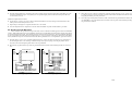
60044WP2
Washer-Extractors
PELLERIN MILNOR CORPORATION
POST OFFICE BOX 400, KENNER, LOUISIANA 70063-0400, U.S.A.
Please Read
About the Manual Identifying Information on the Cover
The front cover displays pertinent identifying information for this manual. Most important, are
the published manual number (part number) /ECN (date code). Generally, when a replacement
manual is furnished, it will have the same published manual number, but the latest available ECN.
This provides the user with the latest information applicable to his machine. Similarly all
documents comprising the manual will be the latest available as of the date the manual was
printed, even though older ECN dates for those documents may be listed in the table of
contents.
When communicating with the Milnor factory regarding this manual, please also provide the
other identifying information shown on the cover, including the publishing system, access date,
and whether the document ECN’s are the latest available or exact.
References to Yellow Troubleshooting Pages
This manual may contain references to “yellow pages.” Although the pages containing
troubleshooting procedures are no longer printed on yellow paper, troubleshooting instructions, if
any, will be contained in the easily located “Troubleshooting” chapter or section. See the table of
contents.
Trademarks of Pellerin Milnor Corporation
The following, some of which may be used in this manual, are trademarks of Pellerin Milnor
Corporation:
Ampsaver®
Autolint®
Auto-Purge®
Autovac
CBW®
Dye-Extractor®
Dyextractor®
E-P Express®
E-P OneTouch®
E-P Plus®
Gear Guardian®
Hands-Off®
Hydro-Cushion®
Mildata®
Milnet®
Milnor®
Miltrac
Miltron
Comments and Suggestions
Help us to improve this manual by sending your comments to:
Pellerin Milnor Corporation
Attn: Technical Publications
P. O. Box 400
Kenner, LA 70063-0400
Fax: (504) 469-1849
Staph-Guard®
System 4®
System 7®
Totaltrol®
Table of Contents
for MPP60WE2AE/2006313A
60044WP2 Washer-Extractors
Page
Description
Document/ECN
1
2
3
4
About This Manual
Warranty
How to Order Parts
Safety„Divided Cylinder and Staph-Guard’ WasherExtractors
About the Forces Transmitted by Milnor Washer-Extractors
Glossary of Tag Illustrations - Suspended WasherExtractors
Avoiding Damage from Allied Remote Chemical
Delivery Systems
MHPHYDROAE/9541AV
9
11
17
23
24
34
35
39
58
63
64
65
67
68
69
70
73
74
84
85
86
87
89
90
92
93
94
95
98
BMP720097/92732A
BMP720097R/72332A
BIUUUS27/20051111
BIWUUI02/20001108
MSIUPUTGAE/2003026V
BIWUUI03/20030306
Section 1: Service and Maintenance
Lubrication and Preventive Maintenance for Hydrocushion
Machines
Lubricants for Milnor Machines
Baldor Motor Maintenance
Fastener Torque Requirements
General Assembly
MSSM0201CE/2004046V
MSSM0132AE/9903AV
MSSM0274AE/9731AV
MSSM0101CE/9906AV
BMP060019/2006185B
Section 2: Shell and Door Assemblies
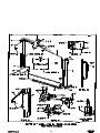
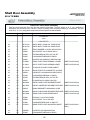
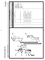
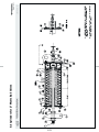
60" & 72" WEH - Shell Door Assembly
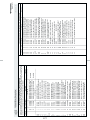
Parts List - Shell Door Assembly, 60 & 72 WEH
Air Operated Vacuum Pump for Door Seals
Door Latch Assembly
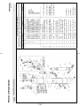
Cylinder Assembly - 6036, 6044, & 7244 WE2
Parts List - Cylinder Assembly, 60 & 70 WE2
BMP780109/81433B
BMP780109R/81433A
BMP810002/81073A
BMP701316/98183V
BMP780043/79221B
BMP780043R/86387A
Section 3: Drive Assemblies
Drive Base Components on Hydro-Cushion Machines
Drive Assembly - 6036WE2, WE3 & 6044WE2, WE3
Parts List - Drive Assembly 6036WE2,WE3,
6044WE2,WE3
Jackshaft Bearing Assembly - 5238, 6036, 6044,
6442 & 7244
Parts List - Jackshaft Bearing Assembly (52, 60, 64, 72)
Reducer Air Seal
Autospot Drive Assembly
Air Operated Autospot Assembly - 60044WP2/WP3
and 72044WP2/WP3
Sensing Unit - Airop Autospot
Parts List - Sensing Unit, Airop Autospot
Brake Assembly
Centrifugal Switch Assembly
MSSMA407BE/85047V
BMP840021/91107D
BMP840021R/2006146B
BMP820109/89253C
BMP820109R/89253A
BMP700392/2002496V
BMP701411/2000133V
BMP710043/96216V
BMP710042/76143D
BMP710042R/85353A
BMP710022/2006155B
BMP701195/2000242V
Table of Contents, cont.
Page
100
101
105
106
116
119
120
121
127
129
131
132
134
135
136
138
139
140
142
144
147
148
150
152
153
156
159
161
163
164
166
169
170
172
174
176
Description
Centrifugal Switch Operation
V-Belt Tension Adjustments for 48", 52", 60"
and 72" Washer-Extractors
Document/ECN
BMP701196/81271A
MSSMA405AE/8737BV
Section 4: Bearing Assemblies
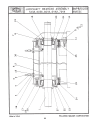
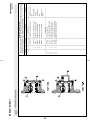
Main Bearing and Seal Replacement for Divided
Cylinder Machines
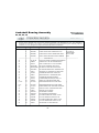
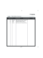
Main Shaft Bearing Assembly
MSSM0303AE/8451BV
BMP840039/2006285B
Section 5: Frame, Pivots and Suspension
Hold Down Adjustments
Suspension Adjustments for Divided Cylinder Machines
Suspension Cylinder Assemblies
Suspension Cylinder Locations
BMP701672/2006295B
MSSM0302AE/8414BV
BMP701408/2006275B
BMP701235/2006304A
Section 6: Control and Sensing Assemblies
Vibration Safety Switch Adjustments
Excursion Switch
Vibration Safety Switch
Water Level Float Chamber
Water Level Switch Assembly
MSSMA408BE/9273BV
BMP060011/2006155B
BMP910038/2006155B
BMP810111/2003262V
BMP800186/2002226V
Section 7: Chemical Supply Devices
Rules for the Field Installation of Pumped-Type
Liquid Supply Systems
Peristaltic Connection
Supply Injector - 6036, 6044 & 5238
MSSM0213AE/89457V
BMP060012/2006155B
BMP700940/97287V
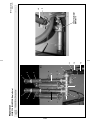
Section 8: Water and Steam Piping Assemblies
Water Inlet
Cooldown Inlet
1.5" Siphon Breaker & Scupper
Steam Inlet
Universal Actuators & Mounting Hardware for
Watts Ball Valves - New Pivot
Watts Ball Valves and Repair Kits
8" & 10" Stainless Dump Valve
BMP060013/2006175B
BMP060017/2006175B
BMP060016/2006182B
BMP060018/2006175B
BMP920005/96067V
BMP920007/96066V
BMP780095/2006185B
Section 9: Pneumatic Piping and Assemblies
Servicing Air Cylinders
Air Cylinder Assemblies
3 Way Pilot Valves
Asco 3-way Solenoid Valves
Pressure Regulators
Quick Exhaust Valves
Air Cylinders for 2"Watts Ball Valves
MSSM0130AE/9313AV
BMP830078/2005525B
BMP900032/91182V
BMP701359/97086V
BMP900031/96081V
BMP701406/2002382V
BMP920006/2000133V
MHPHYDROAE/9541AV (1 of 1)
ABOUT THIS MANUAL
È
Scope—This instruction manual is intended to provide preventive maintenance, service procedures, and
Ë
mechanical parts identification for your machine. See the safety manual for safety instructions before installing,
servicing, or operating this machine. See the installation guide for facility requirements, installation instructions,
and assembly instructions. See the operator guide for operator instructions. See the reference manual for programming, operating, and troubleshooting instructions. See the schematic manual for electrical parts identification and
electrical troubleshooting.
Manual Number/Date Code (When To Discard or Save)—The manual number/date code is loË
cated on the inside front cover, upper right corner just above the manual name. Whenever the manual is reprinted
with new information, part of this number changes. If the date code after the “/” changes, the new version applies
to all machines covered by the old version, but is improved— thus the old version can be discarded. If the
manual number before the “/” changes, the new manual covers only new machines. Example: Discard MATMODELAE/8739CV when MATMODELAE/8739DV is received (minor improvements). Also, discard MATMODELAE/8739DV when MATMODELAE/8746AV is received (major improvements). Bu t k eep
MATMODELAE/8746FV when MATMODELBE/8815AV is received, since the new manual no longer applies to
machines originally shipped with the old manual.
Documents and Change Bars—The individual documents comprising this manual use the same revision
Ë
criteria as the manual. Text documents also display change bars. Example: When section MSOP0599AE/9135BV
becomes MSOP0599AE/9135CV, change bars with the letter “C” appear next to all changes for this revision. For
a major rewrite (e.g., MSOP0599AE/9226AV), all change bars are deleted.
For Assistance—Please call:
Ë
Pellerin Milnor Corporation
Attn: Service Department
P. O. Box 400
Kenner, LA 70063-0400
Phone: (504) 467-9591
Fax: (504) 467-9777
Trademarks of Pellerin Milnor Corporation—The following, some of which may be used in this pubË
lication, are trademarks of Pellerin Milnor Corporation:
Ampsaver®
Autolint®
Auto-Purge®
Autovac
CBW®
Dye-Extractor®
Dyextractor®
E-P Plus®
Gear Guardian®
Hands-Off®
Hydro-Cushion®
Mildata®
1
Milnet®
Milnor®
Miltrac
Miltron
Staph-Guard®
System 4®
System 7®
Totaltrol®
3(//(5,10,/125&25325$7,21
/,0,7('67$1'$5':$55$17<
We warrant to the original purchaser that MILNOR machines including electronic
hardware/software (hereafter referred to as “equipment”), will be free from defects in material
and workmanship for a period of one year from the date of shipment from our factory with no
operating hour limitation. This warranty is contingent upon the equipment being installed,
operated and serviced as specified in the operating manual supplied with the equipment, and
operated under normal conditions by competent operators.
Providing we receive written notification of a warranted defect within 30 days of its discovery,
we will – at our option – repair or replace the defective part or parts, FOB our factory. We
retain the right to require inspection of the parts claimed defective in our factory prior to
repairing or replacing same. We will not be responsible, or in any way liable, for unauthorized
repairs or service to our equipment, and this warranty shall be void if the equipment is repaired
or altered in any way without MILNOR’s written consent.
Parts which require routine replacement due to normal wear – such as gaskets, contact points,
brake and clutch linings and similar parts – are not covered by this warranty, nor are parts
damaged by exposure to weather or to chemicals.
We reserve the right to make changes in the design and/or construction of our equipment
(including purchased components) without obligation to change any equipment previously
supplied.
ANY SALE OR FURNISHING OF ANY EQUIPMENT BY MILNOR IS MADE ONLY UPON
THE EXPRESS UNDERSTANDING THAT MILNOR MAKES NO EXPRESSED OR IMPLIED
WARRANTIES OF MERCHANTABILITY OR FITNESS FOR ANY PARTICULAR USE OR
PURPOSE. MILNOR WILL NOT BE RESPONSIBLE FOR ANY COSTS OR DAMAGES
ACTUALLY INCURRED OR REQUIRED AS A RESULT OF: THE FAILURE OF ANY OTHER
PERSON OR ENTITY TO PERFORM ITS RESPONSIBILITIES, FIRE OR OTHER HAZARD,
ACCIDENT, IMPROPER STORAGE, MISUSE, NEGLECT, POWER OR ENVIRONMENTAL
CONTROL MALFUNCTIONS, DAMAGE FROM LIQUIDS, OR ANY OTHER CAUSE BEYOND
THE NORMAL RANGE OF USE. REGARDLESS OF HOW CAUSED, IN NO EVENT SHALL
MILNOR BE LIABLE FOR SPECIAL, INDIRECT, PUNITIVE, LIQUIDATED, OR
CONSEQUENTIAL COSTS OR DAMAGES, OR ANY COSTS OR DAMAGES WHATSOEVER
WHICH EXCEED THE PRICE PAID TO MILNOR FOR THE EQUIPMENT IT SELLS OR
FURNISHES.
WE NEITHER ASSUME, NOR AUTHORIZE ANY EMPLOYEE OR OTHER PERSON TO
ASSUME FOR US, ANY OTHER RESPONSIBILITY AND/OR LIABILITY IN CONNECTION
WITH THE SALE OR FURNISHING OF OUR EQUIPMENT TO ANY BUYER.
BMP720097
92732A
2
How to order repair parts
Repair parts may be ordered either from the authorized dealer who sold you this
machine, or directly from the MILNOR factory. In most cases, your dealer will
have these parts in stock.
When ordering parts, please be sure to give us the following information:
1. Model and serial number of the machine for which the parts are required
2.
Part number
3. Name of the part
4. Quantity needed
5. Method of shipment desired
6. In correspondence regarding motors or electrical controls, please include all
nameplate data, including wiring diagram number and the make or
manufacturer of the motor or controls.
All parts will be shipped C.O.D. transportation charges collect only.
Please read this manual
It is strongly recommended that you read the installation and operating manual
before attempting to install or operate your machine. We suggest that this manual
be kept in your business office so that it will not become lost.
PELLERIN MILNOR CORPORATION
32%2;.(11(5/$86$
FAX: Administration 504/468-9307, Engineering 504/469-1849, Service 504/469-9777
BMP720097R
72332A
3
BIUUUS27 (Published) Book specs- Dates: 20051111 / 20051111 / 20060323 Lang: ENG01 Applic: HDU
Safety—Divided Cylinder and Staph-Guard™ Washer-Extractors
1.
General Safety Requirements—Vital Information for
Management Personnel [Document BIUUUS04]
Incorrect installation, neglected preventive maintenance, abuse, and/or improper repairs, or
changes to the machine can cause unsafe operation and personal injuries, such as multiple
fractures, amputations, or death. The owner or his selected representative (owner/user) is
responsible for understanding and ensuring the proper operation and maintenance of the machine.
The owner/user must familiarize himself with the contents of all machine instruction manuals.
The owner/user should direct any questions about these instructions to a Milnor® dealer or the
Milnor® Service department.
Most regulatory authorities (including OSHA in the USA and CE in Europe) hold the owner/user
ultimately responsible for maintaining a safe working environment. Therefore, the owner/user
must do or ensure the following:
• recognize all foreseeable safety hazards within his facility and take actions to protect his
personnel, equipment, and facility;
• work equipment is suitable, properly adapted, can be used without risks to health or safety,
and is adequately maintained;
• where specific hazards are likely to be involved, access to the equipment is restricted to those
employees given the task of using it;
• only specifically designated workers carry out repairs, modifications, maintenance, or
servicing;
• information, instruction, and training is provided;
• workers and/or their representatives are consulted.
Work equipment must comply with the requirements listed below. The owner/user must verify
that installation and maintenance of equipment is performed in such a way as to support these
requirements:
• control devices must be visible, identifiable, and marked; be located outside dangerous zones;
and not give rise to a hazard due to unintentional operation;
• control systems must be safe and breakdown/damage must not result in danger;
• work equipment is to be stabilized;
• protection against rupture or disintegration of work equipment;
• guarding, to prevent access to danger zones or to stop movements of dangerous parts before
the danger zones are reached. Guards to be robust; not give rise to any additional hazards; not
be easily removed or rendered inoperative; situated at a sufficient distance from the danger
zone; not restrict view of operating cycle; allow fitting, replacing, or maintenance by
restricting access to relevant area and without removal of guard/protection device;
• suitable lighting for working and maintenance areas;
• maintenance to be possible when work equipment is shut down. If not possible, then
protection measures to be carried out outside danger zones;
• work equipment must be appropriate for preventing the risk of fire or overheating; discharges
of gas, dust, liquid, vapor, other substances; explosion of the equipment or substances in it.
PELLERIN MILNOR CORPORATION
4
Safety—Divided Cylinder and Staph-Guard™ Washer-Extractors
1.1.
Laundry Facility—Provide a supporting floor that is strong and rigid enough to support–with
a reasonable safety factor and without undue or objectionable deflection–the weight of the fully
loaded machine and the forces transmitted by it during operation. Provide sufficient clearance for
machine movement. Provide any safety guards, fences, restraints, devices, and verbal and/or
posted restrictions necessary to prevent personnel, machines, or other moving machinery from
accessing the machine or its path. Provide adequate ventilation to carry away heat and vapors.
Ensure service connections to installed machines meet local and national safety standards,
especially regarding the electrical disconnect (see the National Electric Code). Prominently post
safety information, including signs showing the source of electrical disconnect.
1.2.
Personnel—Inform personnel about hazard avoidance and the importance of care and
common sense. Provide personnel with the safety and operating instructions that apply to them.
Verify that personnel use proper safety and operating procedures. Verify that personnel
understand and abide by the warnings on the machine and precautions in the instruction manuals.
1.3.
Safety Devices—Ensure that no one eliminates or disables any safety device on the machine
or in the facility. Do not allow machine to be used with any missing guard, cover, panel or door.
Service any failing or malfunctioning device before operating the machine.
1.4.
Hazard Information—Important information on hazards is provided on the machine safety
placards, in the Safety Guide, and throughout the other machine manuals. Placards must be kept
clean so that the information is not obscured. They must be replaced immediately if lost or
damaged. The Safety Guide and other machine manuals must be available at all times to
the appropriate personnel. See the machine service manual for safety placard part numbers.
Contact the Milnor Parts department for replacement placards or manuals.
1.5.
2.
Maintenance—Ensure the machine is inspected and serviced in accordance with the norms of
good practice and with the preventive maintenance schedule. Replace belts, pulleys, brake
shoes/disks, clutch plates/tires, rollers, seals, alignment guides, etc. before they are severely
worn. Immediately investigate any evidence of impending failure and make needed repairs (e.g.,
cylinder, shell, or frame cracks; drive components such as motors, gear boxes, bearings, etc.,
whining, grinding, smoking, or becoming abnormally hot; bending or cracking of cylinder, shell,
frame, etc.; leaking seals, hoses, valves, etc.) Do not permit service or maintenance by
unqualified personnel.
Safety Alert Messages—Internal Electrical and Mechanical
Hazards [Document BIUUUS11]
The following are instructions about hazards inside the machine and in electrical enclosures.
WARNING 1 : Electrocution and Electrical Burn Hazards—Contact with electric power
can kill or seriously injure you. Electric power is present inside the cabinetry unless the main
machine power disconnect is off.
• Do not unlock or open electric box doors.
• Do not remove guards, covers, or panels.
• Do not reach into the machine housing or frame.
• Keep yourself and others off of machine.
• Know the location of the main machine disconnect and use it in an emergency to remove
all electric power from the machine.
PELLERIN MILNOR CORPORATION
5
WARNING 2 : Entangle and Crush Hazards—Contact with moving components normally
isolated by guards, covers, and panels, can entangle and crush your limbs. These components
move automatically.
• Do not remove guards, covers, or panels.
• Do not reach into the machine housing or frame.
• Keep yourself and others off of machine.
• Know the location of all emergency stop switches, pull cords, and/or kick plates and use
them in an emergency to stop machine motion.
3.
Safety Alert Messages—External Mechanical Hazards [Document
BIUUUS12]
The following are instructions about hazards around the front, sides, rear or top of the machine.
WARNING 3 : Crush Hazards—Suspended machines only—Spaces between the shell and
housing can close and crush or pinch your limbs. The shell moves within the housing during
operation.
• Do not reach into the machine housing or frame.
• Keep yourself and others clear of movement areas and paths.
4.
Safety Alert Messages—Cylinder and Processing Hazards
[Document BIUUUS13]
The following are instructions about hazards related to the cylinder and laundering process.
WARNING 4 : Crush Hazards—Contact with the turning cylinder can crush your limbs. The
cylinder will repel any object you try to stop it with, possibly causing the object to strike or stab
you. The turning cylinder is normally isolated by the locked cylinder door.
• Do not attempt to open the door or reach into the cylinder until the cylinder is stopped.
• Do not place any object in the turning cylinder.
• Do not operate the machine with a malfunctioning door interlock.
• Divided cylinder machines only—Keep yourself and others clear of cylinder and goods
during inching or Autospot operation.
• Do not operate the machine with malfunctioning two-hand manual controls.
WARNING 5 : Confined Space Hazards—Confinement in the cylinder can kill or injure
you. Hazards include but are not limited to panic, burns, poisoning, suffocation, heat prostration,
biological contamination, electrocution, and crushing.
• Do not attempt unauthorized servicing, repairs, or modification.
WARNING 6 : Explosion and Fire Hazards—Flammable substances can explode or ignite
in the cylinder, drain trough, or sewer. The machine is designed for washing with water, not any
other solvent. Processing can cause solvent-containing goods to give off flammable vapors.
• Do not use flammable solvents in processing.
• Do not process goods containing flammable substances. Consult with your local fire
department/public safety office and all insurance providers.
PELLERIN MILNOR CORPORATION
6
Safety—Divided Cylinder and Staph-Guard™ Washer-Extractors
5.
5.1.
5.1.1.
Safety Alert Messages—Unsafe Conditions [Document BIUUUS14]
Damage and Malfunction Hazards
Hazards Resulting from Inoperative Safety Devices
DANGER 7 : Entangle and Sever Hazards—Cylinder door interlock—Operating the
machine with a malfunctioning door interlock can permit opening the door when the cylinder is
turning and/or starting the cycle with the door open, exposing the turning cylinder.
• Do not operate the machine with any evidence of damage or malfunction.
WARNING 8 : Multiple Hazards—Operating the machine with an inoperative safety device
can kill or injure personnel, damage or destroy the machine, damage property, and/or void the
warranty.
• Do not tamper with or disable any safety device or operate the machine with a
malfunctioning safety device. Request authorized service.
WARNING 9 : Electrocution and Electrical Burn Hazards—Electric box doors—
Operating the machine with any electric box door unlocked can expose high voltage conductors
inside the box.
• Do not unlock or open electric box doors.
WARNING 10 : Entangle and Crush Hazards—Guards, covers, and panels—Operating
the machine with any guard, cover, or panel removed exposes moving components.
• Do not remove guards, covers, or panels.
5.1.2.
Hazards Resulting from Damaged Mechanical Devices
WARNING 11 : Multiple Hazards—Operating a damaged machine can kill or injure
personnel, further damage or destroy the machine, damage property, and/or void the warranty.
• Do not operate a damaged or malfunctioning machine. Request authorized service.
WARNING 12 : Explosion Hazards—Cylinder—A damaged cylinder can rip apart during
extraction, puncturing the shell and discharging metal fragments at high speed.
• Do not operate the machine with any evidence of damage or malfunction.
WARNING 13 : Explosion Hazards—Inner door latches (divided cylinder machines)—A
damaged or improperly seated latch can cause the inner door to open during operation, damaging
the cylinder and shell. A damaged cylinder can rip apart during extraction, puncturing the shell
and discharging metal fragments at high speed.
• Ensure that the inner door is securely latched when loading and unloading.
• Do not operate the machine with any evidence of damage or malfunction.
WARNING 14 : Explosion Hazards—Clutch and speed switch (multiple motor
machines)—A damaged clutch or speed switch can permit the low speed motor to engage during
extract. This will over-speed the motor and pulleys and can cause them to rip apart, discharging
metal fragments at high speed.
• Stop the machine immediately if any of these conditions occur: • abnormal whining sound
during extract • skidding sound as extract ends • clutches remain engaged or re-engage
during extract
PELLERIN MILNOR CORPORATION
7
5.2.
5.2.1.
Careless Use Hazards
Careless Operation Hazards—Vital Information for Operator Personnel (see also
operator hazards throughout manual)
WARNING 15 : Multiple Hazards—Careless operator actions can kill or injure personnel,
damage or destroy the machine, damage property, and/or void the warranty.
• Do not tamper with or disable any safety device or operate the machine with a
malfunctioning safety device. Request authorized service.
• Do not operate a damaged or malfunctioning machine. Request authorized service.
• Do not attempt unauthorized servicing, repairs, or modification.
• Do not use the machine in any manner contrary to the factory instructions.
• Use the machine only for its customary and intended purpose.
• Understand the consequences of operating manually.
5.2.2.
Careless Servicing Hazards—Vital Information for Service Personnel (see also
service hazards throughout manuals)
WARNING 16 : Electrocution and Electrical Burn Hazards—Contact with electric
power can kill or seriously injure you. Electric power is present inside the cabinetry unless the
main machine power disconnect is off.
• Do not service the machine unless qualified and authorized. You must clearly understand
the hazards and how to avoid them.
• Abide by the current OSHA lockout/tagout standard when lockout/tagout is called for in
the service instructions. Outside the USA, abide by the OSHA standard in the absence of
any other overriding standard.
WARNING 17 : Entangle and Crush Hazards—Contact with moving components
normally isolated by guards, covers, and panels, can entangle and crush your limbs. These
components move automatically.
• Do not service the machine unless qualified and authorized. You must clearly understand
the hazards and how to avoid them.
• Abide by the current OSHA lockout/tagout standard when lockout/tagout is called for in
the service instructions. Outside the USA, abide by the OSHA standard in the absence of
any other overriding standard.
WARNING 18 : Confined Space Hazards—Confinement in the cylinder can kill or injure
you. Hazards include but are not limited to panic, burns, poisoning, suffocation, heat prostration,
biological contamination, electrocution, and crushing.
• Do not enter the cylinder until it has been thoroughly purged, flushed, drained, cooled,
and immobilized.
— End of BIUUUS27 —
PELLERIN MILNOR CORPORATION
8
About the Forces Transmitted by Milnor® Washer-extractors
About the Forces Transmitted by Milnor®
Washer-extractors
Document ..................... BIWUUI02
Specified Date ................. 20001108
As-of Date ....................... 20001108
Access Date ..................... 20001108
Applicability...........................WUU
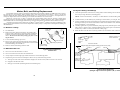
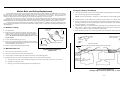
During washing and extracting, all washer-extractors transmit both static and dynamic
(cyclic) forces to the floor, foundation, or any other supporting structure. During washing, the
impact of the goods as they drop imparts forces which are quite difficult to quantify. Size for size,
both rigid and flexibly-mounted machines transmit approximately the same forces during
washing. During extracting, rigid machines transmit forces up to 30 times greater than equivalent
flexibly-mounted models. The actual magnitude of these forces vary according to several factors:
•
•
•
•
•
machine size,
final extraction speed,
amount, condition, and type of goods being processed,
the liquor level and chemical conditions in the bath preceding extraction, and
other miscellaneous factors.
Estimates of the maximum force normally encountered are available for each Milnor® model
and size upon request. Floor or foundation sizes shown on any Milnor® document are only for
on-grade situations based only on previous experience without implying any warranty, obligation,
or responsibility on our part.
1.
Rigid Machines
Size for size, rigid washer-extractors naturally require a stronger, more rigid floor,
foundation, or other supporting structure than flexibly-mounted models. If the supporting soil
under the slab is itself strong and rigid enough and has not subsided to leave the floor slab
suspended without support, on grade installations can often be made directly to an existing floor
slab if it has enough strength and rigidity to safely withstand our published forces without
transmitting undue vibration. If the subsoil has subsided, or if the floor slab itself has insufficient
strength and rigidity, a deeper foundation, poured as to become monolithic with the floor slab,
may be required. Support pilings may even be required if the subsoil itself is “springy” (i.e., if its
resonant frequency is near the operating speed of the machine). Above-grade installations of rigid
machines also require a sufficiently strong and rigid floor or other supporting structure as
described below.
2.
Flexibly-mounted Machines
Size for size, flexibly-mounted machines generally do not require as strong a floor,
foundation, or other supporting structure as do rigid machines. However, a floor or other
supporting structure having sufficient strength and rigidity, as described in section 3, is
nonetheless vitally important for these models as well.
3.
How Strong and Rigid?
Many building codes in the U.S.A. specify that laundry floors must have a minimum live
load capacity of 150 pounds per square foot (732 kilograms per square meter). However, even
compliance with this or any other standard does not necessarily guarantee sufficient rigidity. In
any event, it is the sole responsibility of the owner/user to assure that the floor and/or any other
supporting structure exceeds not only all applicable building codes, but also that the floor and/or
any other supporting structure for each washer-extractor or group of washer-extractors actually
9
has sufficient strength and rigidity, plus a reasonable factor of safety for both, to support the
weight of all the fully loaded machine(s) including the weight of the water and goods, and
including the published 360º rotating sinusoidal RMS forces that are transmitted by the
machine(s). Moreover, the floor, foundation, or other supporting structure must have sufficient
rigidity (i.e., a natural or resonant frequency many times greater than the machine speed with a
reasonable factor of safety); otherwise, the mentioned 360º rotating sinusoidal RMS forces can be
multiplied and magnified many times. It is especially important to consider all potential vibration
problems that might occur due to all possible combinations of forcing frequencies (rotating
speeds) of the machine(s) compared to the natural frequencies of the floor and/or any other
supporting structure(s). A qualified soil and/or structural engineer must be engaged for this
purpose.
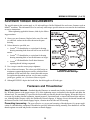
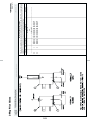
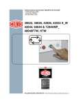
Figure 1: How Rotating Forces Act on the Foundation
Typical Machine
Legend
A.
B.
C.
Direction of force
Load
Rotation (Frequency = RPM / 60)
Figure 1 above is intended to depict both on-grade and above-grade installations and is
equally applicable to flexibly-mounted washer-extractors, as well as to rigid models installed
either directly on a floor slab or on a foundation poured integrally with the slab. Current machine
data is available from Milnor® upon request. All data is subject to change without notice and may
have changed since last printed. It is the sole responsibility of every potential owner to obtain
written confirmation that any data furnished by Milnor® applies for the model(s) and serial
number(s) of the specific machines.
— End of BIWUUI02 —
10
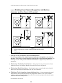
7\_ccQbi_VDQW9\\ecdbQdY_^c±
Cec`U^TUTGQcXUb5hdbQSd_bc
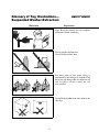
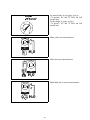
Illustration
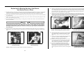
<B8D?DC604!"!%E
Explanation
Stop! Read the manual first for complete
instructions before continuing.
Do not jack the machine here.
Do not lift the machine here.
Use three point or four point lifting as
determined by the lifting eyes furnished. Rig
the load using lifting cables of sufficient size
and length to ensure cables are not
over-stressed.
Do not lift the machine from one corner or one
side edge.
11
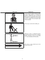
Illustration
Explanation
Do not start this machine until the packing
materials, lifting brackets, etc. with this tag
attached or behind this panel are removed.
These materials are painted red. Safety stands
or brackets (also painted red) may be provided
with this machine. Do not discard safety
stands or brackets
Do not step or stand on this machine part.
Maintain a 25 mm. (1") minimum clearance
between float clips. Set "low level" so that the
bottom of the float is always at least 25mm
(1") above the bottom of the float tube.
This motor or pump should rotate in the
direction of the arrow.
12
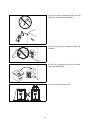
7\_ccQbi _V DQW 9\\ecdbQdY_^c±
Cec`U^TUT GQcXUb5hdbQSd_bc
Do not start this machine until the part with
this tag is installed on the machine.
Do not remove this component from the
machine.
Install the appropriate part here before
operating the machine.
Do not strap or chain over box
13
=C9E@ED715"
# "&F " #
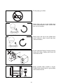
Do not pump grease here.
During drain and extract, the cylinder must
rotate counterclockwise when viewed from
here (rear of machine).
During drain and extract, the cylinder must
rotate clockwise when viewed from here
(front of machine).
Do not strike shell front of washer-extractors
during fork lifting. Striking shell front will
cause door to leak.
Brake assembly under machine is fragile.
Forklift blades should only be placed under
main structural beams
14
7\_ccQbi _V DQW 9\\ecdbQdY_^c±
Cec`U^TUT GQcXUb5hdbQSd_bc
Set main bearing air pad gauge at 10 psi
(.70 kg/cm2), 64" and 72" ExN and JxN
models only.
Set disc brake air gauge at 10 psi
(.70 kg/cm2), 64" and 72" ExN and JxN
models only.
Make cold water connection here.
H20
Make hot water connection here.
H20
Make third (reuse) water connection here.
H20
15
=C9E@ED715"
# "&F # #
Hold the connection side of the valve with a
wrench when connecting plumbing.
16
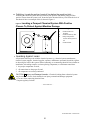
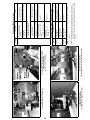
BIWUUI03 (Published) Book specs- Dates: 20030306 / 20030306 / 20030306 Lang: ENG01 Applic: WUU
Avoiding Damage From Allied Remote Chemical Delivery
Systems
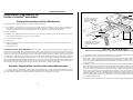
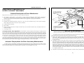
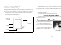
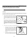
Milnor® does not manufacture or supply remote chemical delivery systems and this document is
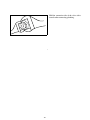
meant only to illustrate some of the possible problems that can be minimized during installation
of such systems by the chemical supply company. Milnor washer-extractors and CBW® batch
washers (tunnels) are available with convenient inlets for such systems (see Figure 1). Most
common of the types of systems currently used in commercial laundering operations are pumped
chemical systems. Other types, such as constant pressure, re-circulating ring main systems have
also been, and may continue to be used with Milnor equipment.
This document warns about some of the possible hazards posed by chemical systems and lists
certain requirements needed to minimize those hazards. The procedures for interfacing with allied
chemical systems and information pertinent to chemical use in general are provided elsewhere in
the product manuals (see Note 1).
Figure 1: Pumped Chemical Inlets on CBW Batch Washer
Note 1: Misuse of laundering chemicals (such as injecting excessive concentrations of chlorine bleach or
permitting acid sours to react with hypo chlorite) due to incorrect formulation can also be hazardous.
Information pertinent to chemical use is provided elsewhere in the product manuals.
1.
How a Chemical System Can Damage the Machine It Serves
Milnor has manufactured washer-extractors and tunnel washers with the same stainless steel
specification since its founding. Every batch of steel used is certified and documented by the steel
mill. Testing of samples damaged by corrosion have, in every case, proven the steel to be well
within the AISI 304 specification.
PELLERIN MILNOR CORPORATION
17
Avoiding Damage From Allied Remote Chemical Delivery Systems
Chemical products commonly found in the laundry industry, when used in established dosages
and proper operating parameters, under the auspices of an experienced chemical specialist, should
produce satisfactory results, with no consequential detrimental effects. The industry has published
standards in Riggs and Sherrill, “Textile Laundering Technology”. However, the stainless steel
can be damaged and even destroyed by abnormal contact with chlorine bleach, hydrofluosilicic
acid and other commonly used chemicals, as will occur if chemicals are unintentionally leaked
into the machine, particularly when it is no longer in use and especially when machine surfaces
are dry.
Some chemical systems have been found to permit chemicals to dribble from the supply lines, or
worse, to siphon from the supply tank into the machine, during operation and long after the
system is shut down—as after working hours and during weekends. If this occurs, deterioration
(rusting) of the stainless steel and damage to any textiles therein will inevitably result. If this
condition goes undetected, machine damage is likely to be catastrophic. No machine is
immune to such damage.
CAUTION 1 : Equipment and Textile Damage Hazards—Chemicals leaked into the
machine, particularly when it is idle can destroy machine components and textiles left in the
machine. Pellerin Milnor Corporation accepts absolutely no responsibility for damage to its
equipment or to textiles therein from abnormal contact with chemicals.
• Ensure that the chemical system prevents unintentional release of chemicals.
• Inspect regularly for proper operation and evidence of damage.
2.
Requirements for Chemical Systems Used With Milnor Machines
It is the responsibility of the chemical system manufacturer and supplier to ensure that their
system is safe for personnel and equipment. Some important points are described below.
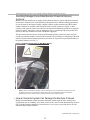
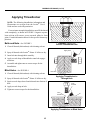
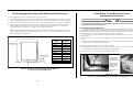
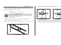
2.1.
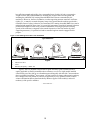
Ensure the System Cannot Siphon.—The supply system must be designed to
counteract any siphoning that could occur as a result of having a sealed supply line between the
bottom of the chemical tank and the internal machine connection at the drain trough. As shown in
the Figure 2 examples, if the pump (P) and/or the valving does not provide positive closure and
there is no vacuum breaker protection, siphoning is likely to occur. In each of the Figure 2
illustrations, the volume of chemical in the tank above the siphon level (S), and indicated by
shading, will flow into the machine.
PELLERIN MILNOR CORPORATION
18
Figure 2: Siphoning
From the Chemical Tank into the Machine
Examples
Legend
P.
S.
T.
2.2.
Pump
Siphon level. Shading indicates the chemical delivery line and tank content that can siphon into
the machine.
Chemical tank
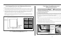
Ensure the Chemical Lines Cannot Dribble—The pumped chemical system may
provide a means of positively closing the chemical line at the pump location, but not at the
injection site. Hence, any concentrated chemical that remains in the injection line between the
pump and the machine is free to flow into the machine. Some examples of this are shown in
Figure 3.
PELLERIN MILNOR CORPORATION
19
Avoiding Damage From Allied Remote Chemical Delivery Systems
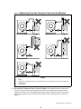
Figure 3: Dribbling
From Chemical Supply Line Into Machine
(assumes positive closure at the pump)
Examples
Legend
D.
P.
T.
3.
Portion of supply line, the contents of which can dribble into the machine
Pump
Chemical tank
Design and Installation Recommendations
It is the responsibility of the chemical system manufacturer and supplier to use whatever
measures are necessary to ensure that their system is safe for personnel and equipment. The
following are some of the possible methods the manufacturer or supplier may wish to use, as
appropriate.
3.1.
Siphoning: Positively close the line.—If the pump does not provide positive closure
when the system is off, employ a shutoff valve in the line to serve this purpose.
3.2.
Siphoning: Break the siphon.—Provide an air gap or vacuum breaker in the chemical
delivery line. This must be located above the “full” line of the tank.
3.3.
Dribbling: Flush the entire chemical delivery line.—If any concentrated chemical
that remains in the injection line between the pump and the machine is free to flow into the
machine, employ a system that flushes the entire line between the pump and the injection point
with fresh water after each injection.
PELLERIN MILNOR CORPORATION
20
3.4.
Dribbling: Locate the entire chemical line below the machine inlet.—
Assuming the chemical system does not retain any line pressure and that the pump provides
positive closure when the system is off, locate the entire chemical delivery line below the level of
the chemical inlet. An example of this is shown in Figure 4.
Figure 4: Locating
a Pumped Chemical System With Positive
Closure To Protect Against Machine Damage
Example of Correct Placement
Legend
I.
L.
P.
T.
4.
Chemical inlet on
machine
Chemical delivery line
Pump with positive
closure when system is
off
Chemical tank
Guarding Against Leaks
All personnel who may work with the chemical system (e.g., chemical system manufacturer,
chemical system supplier, chemical supplier, operator, maintenance personnel) should be vigilant
in observing for leaks in the system. When connecting, or reconnecting chemical lines, whether at
installation, after taking samples, or when replacing components, at a minimum ensure that:
1. the proper components are used,
2. all connections are the proper fit, and
3. all components are securely connected.
CAUTION 2 : Injury and Damage Hazards—Chemicals leaking from a chemical system
may be corrosive or toxic. Such chemicals can injure personnel and damage equipment.
• Use care when connecting chemical lines.
• Inspect regularly for leaks.
— End of BIWUUI03 —
PELLERIN MILNOR CORPORATION
21
22
Section
Service and Maintenance
23
1
MSSM0201CE/2004046V
ÈUBRICATION AND PREVENTIVE MAINTENANCE
L
FOR HYDRO-CUSHION® MACHINES
General Requirements
Ê
CRUSH/SEVER HAZARD—Tilting machines with tilt wheels/cradles may lunge
forward or rearward and even fall over if the tilt wheels at the non-tilted end are
raised out of their cradles—killing/injuring personnel and/or damaging property.
Maintenance procedures require:
☞ NEVER manually tilt (lift) both ends of the machine at the same time. One end must
always be seated in its cradle.
• A hand operated grease gun.
☞ ALWAYS visually inspect the tilt wheels to be sure they are all fully seated in their cradles before each manual tilt up.
• The correct lubricants (see “LUBRICANTS FOR MILNOR MACHINES,” in the Table of Contents).
Lubricant Requirements
Ê
To achieve the optimum performance and service life from the Milnor® machine and as a warranty requirement, the machine must be lubricated in strict accordance with the instructions in this section.
☞ Hydraulic valve manual operation must be done by trained competent maintenance personnel who thoroughly understand the system and all the consequences of manual
operations.
☞ ALWAYS understand beforehand all the consequences of manually operating hydraulic
valves.
☞ Never permit operation with malfunctioning tilt limit switches.
Correct Grease Gun Procedures
Ê
ENTANGLE AND CRUSH HAZARD—Belts and pulleys can entangle and crush
body parts.
☞ Lock OFF and tag out power at the wall disconnect before servicing, except
where specifically instructed otherwise in this section.
☞ Insure belt and pulley guards are in place during service procedures.
☞ Permit only qualified maintenance personnel to perform these procedures.
CRUSH/SEVER HAZARD—Tilting mechanism can crush or sever parts of your
body caught in them.
☞ Install the safety stands before performing maintenance under a tilted machine.
☞ NEVER test or operate (manually or automatically) any machine function
with any portion of a person’s body under the tilted machine—even if the
safety stands are installed.
24
1. Do not use a pneumatic grease gun. Pump grease slowly, taking 10-15 seconds to complete each stroke.
A grease gun can build up extremely high pressure which will force seals out of position and cause them to
leak, even though both the seal and the bearing housing are equipped with spring loaded relief plugs.
2. Apply quantity of grease called for in the checklist. Over-lubrication can be as damaging as under-lubrication. Where quantities are stated in strokes, one stroke of the grease gun is assumed to provide .0624 fluid
ounces (1.77 grams) (by volume) of grease. Therefore, one fluid ounce (28.3 grams) of grease would be provided by 16 strokes of the grease gun. Determine the flow rate of your grease gun by pumping one ounce
into a calibrated container. If fewer than 16 strokes are required, all quantities in strokes in the chart should
be reduced accordingly, and if more than 16 strokes are required, the number of strokes should be increased.
Before starting lubrication, make sure your grease gun is working and that you get a full charge of
grease with every stroke.
3. Do not pump grease in until it oozes out of the spring loaded relief plugs. Plugs bleed out excess grease
and help prevent abnormal pressures from building up in the housing during operation (especially when the
machine is first commissioned and after each lubrication). Plugs will not protect against over-lubrication.
4. Do not over-lubricate motors. Over-lubrication of a motor can seriously damage it by forcing grease into
motor windings. Over-lubrication of the extract motor can force grease into the centrifugal switch causing it
to malfunction.
5. Do not allow grease to drip on the brake disk or clutch tire/drum during lubrication. This will reduce
the braking action considerably, and may permit the cylinder to creep while loading and unloading.
MSSM0201CE/2004046V (1 of 9)
ÈUBRICATION AND PREVENTIVE MAINTENANCE
L
FOR HYDRO-CUSHION® MACHINES
General Requirements
Ê
CRUSH/SEVER HAZARD—Tilting machines with tilt wheels/cradles may lunge
forward or rearward and even fall over if the tilt wheels at the non-tilted end are
raised out of their cradles—killing/injuring personnel and/or damaging property.
Maintenance procedures require:
☞ NEVER manually tilt (lift) both ends of the machine at the same time. One end must
always be seated in its cradle.
• A hand operated grease gun.
☞ ALWAYS visually inspect the tilt wheels to be sure they are all fully seated in their cradles before each manual tilt up.
• The correct lubricants (see “LUBRICANTS FOR MILNOR MACHINES,” in the Table of Contents).
Lubricant Requirements
Ê
To achieve the optimum performance and service life from the Milnor® machine and as a warranty requirement, the machine must be lubricated in strict accordance with the instructions in this section.
☞ Hydraulic valve manual operation must be done by trained competent maintenance personnel who thoroughly understand the system and all the consequences of manual
operations.
☞ ALWAYS understand beforehand all the consequences of manually operating hydraulic
valves.
☞ Never permit operation with malfunctioning tilt limit switches.
Correct Grease Gun Procedures
Ê
ENTANGLE AND CRUSH HAZARD—Belts and pulleys can entangle and crush
body parts.
☞ Lock OFF and tag out power at the wall disconnect before servicing, except
where specifically instructed otherwise in this section.
☞ Insure belt and pulley guards are in place during service procedures.
☞ Permit only qualified maintenance personnel to perform these procedures.
CRUSH/SEVER HAZARD—Tilting mechanism can crush or sever parts of your
body caught in them.
☞ Install the safety stands before performing maintenance under a tilted machine.
☞ NEVER test or operate (manually or automatically) any machine function
with any portion of a person’s body under the tilted machine—even if the
safety stands are installed.
1. Do not use a pneumatic grease gun. Pump grease slowly, taking 10-15 seconds to complete each stroke.
A grease gun can build up extremely high pressure which will force seals out of position and cause them to
leak, even though both the seal and the bearing housing are equipped with spring loaded relief plugs.
2. Apply quantity of grease called for in the checklist. Over-lubrication can be as damaging as under-lubrication. Where quantities are stated in strokes, one stroke of the grease gun is assumed to provide .0624 fluid
ounces (1.77 grams) (by volume) of grease. Therefore, one fluid ounce (28.3 grams) of grease would be provided by 16 strokes of the grease gun. Determine the flow rate of your grease gun by pumping one ounce
into a calibrated container. If fewer than 16 strokes are required, all quantities in strokes in the chart should
be reduced accordingly, and if more than 16 strokes are required, the number of strokes should be increased.
Before starting lubrication, make sure your grease gun is working and that you get a full charge of
grease with every stroke.
3. Do not pump grease in until it oozes out of the spring loaded relief plugs. Plugs bleed out excess grease
and help prevent abnormal pressures from building up in the housing during operation (especially when the
machine is first commissioned and after each lubrication). Plugs will not protect against over-lubrication.
4. Do not over-lubricate motors. Over-lubrication of a motor can seriously damage it by forcing grease into
motor windings. Over-lubrication of the extract motor can force grease into the centrifugal switch causing it
to malfunction.
5. Do not allow grease to drip on the brake disk or clutch tire/drum during lubrication. This will reduce
the braking action considerably, and may permit the cylinder to creep while loading and unloading.
25
26
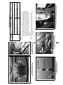
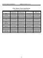
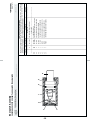
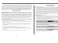
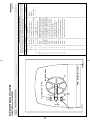
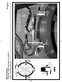
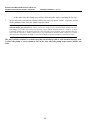
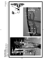
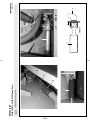
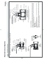
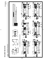
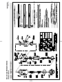
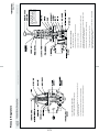
ÎFIGURE 3 (MSSM0201CE)
ÎTypical Upper Hydro-Cushion®
Grease Fitting
Î IGURE 1 (MSSM0201CE)
F
ÎHydraulic Fluid Reservoir Fill and Level Check Point
(located at rear of 48", 52", and 72" tilt machines only)
ÎFIGURE 2 (MSSM0201CE)
ÎTypical Hydro-Cushion®
Maintenance Points
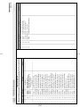
Final stage and other v-belts
(throughout all machines)
FIGURES 1 and 12
NOTES 2 and 3
Hydro-Cushions®
(all machines)
FIGURES 2 and 3
Hydraulic Tilt System
(48", 52", and 72" Tilt machines)
• Reservoir
FIGURE 1 and NOTE 1
Component
Check for wear and
tension
Check for leaks
Check fluid with
machine not tilted
Action
NOTE 3: All v-belts are not alike. “Super” or “High Capacity” v-belts frequently have considerably higher
capacities than “Standard” belts. Sometimes, one brand of v-belt is more suitable than another
brand of v-belt, although both v-belts are “interchangable”. It is always best to purchase replacement
belts from the original manufacturer of the equipment. Purchasing exact replacements of the
original belts is the best way to assure belt life equal to the original set.
Occasionally, Milnor® will change a belt specification to improve belt life.
Belts purchased from Milnor® are as currently specified.
NOTE 2: V-belt instructions for the first week of operation
• After 24 hours operation (three eight hour days), tighten final stage v-belts.
• After 80 hours operation (ten eight hour days), tighten final stage v-belts again.
• After 160 hours of operation (twenty eight hour days), tighten final stage
v-belts, and check all other v-belts and tighten if necessary.
NOTE 1: Tank should be approximately three-quarters full when the machine is not tilted. Do not over-fill.
Weekly
Daily
Frequency
ÏDaily and Weekly Maintenance Items
27
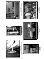
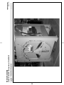
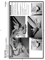
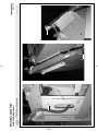
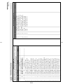
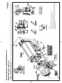
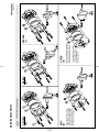
ÎFIGURE 6 (MSSM0201CE)
Î42" Divided Cylinder Rear Bearing
and Seal Grease Fittings
ÎFIGURE 4 (MSSM0201CE)
Î 2" Divided Cylinder Front
4
Bearing and Seal Grease Fittings
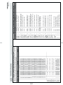
®
0.37 ounces (10.6 grams),
six strokes at two locations
0.12 ounces (3.54 grams),
two strokes at two locations
• Each seal grease
fitting
Action
• Each bearing grease fitting
Ï
ÎFIGURE 8 (MSSM0201CE)
Î60" and 72" Divided Cylinder Rear Seal and Bearing
NOTE 6: Bearings can run hot enough to make it extremely uncomfortable for a
person to hold his hand on the bearing housing for more than a few seconds.
This is normal.
NOTE 5: Main bearings and jackshaft bearings (if so equipped) are prepacked with
lubricant at the factory. Do not add grease for thirty days. During the first
month’s operation, some grease will ooze out of the automatic grease fittings
at the bottom of the housing(s). This is normal. These grease fittings allow
excess grease to escape, thus avoiding over-heating. This escaping lubricant
need not be replaced. Every time these bearings are lubricated, the surplus
grease will come out of the spring loaded relief fittings after a few hours
running time.
NOTE 4: Once a month or once every 200 operating hours, whichever occurs first.
ÎFIGURE 7 (MSSM0201CE)
Î60" and 72" Divided Cylinder Front
Seal and Bearing Grease Fittings
ÎFIGURE 5 (MSSM0201CE)
Î 2" Staph-Guard® Front and
4
Rear Bearing and Seal Grease
Component
Monthly
All Divided cylinder and Staph-Guard main bearing and seals
(see NOTE 4 )
FIGURES 4 through 10, NOTES 5 and 6
Frequency
ÏMonthly Maintenance Items
28
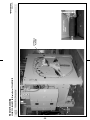
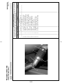
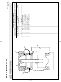
ÎFIGURE 13 (MSSM0201CE)
ÎHydrocushion Bypass Valve
(48" machines only")
Hydro-cushion bypass
Î IGURE 10 (MSSM0201CE)
F
Î60044 and 72044 Staph-Guard® Rear
Bearing and Seal Grease Fittings (lo-
Î IGURE 12 (MSSM0201CE)
F
Î ypical Drive Train Components (48" machine shown)
T
Î IGURE 9 (MSSM0201CE)
F
Î60044 and 72044 Staph-Guard®
Front Bearing and Seal Grease Fit-
ÎFIGURE 11 (MSSM0201CE)
ÎAll Open-Pocket Machine Seal and
Bearing
Grease Fitting Plate
Action
0.06 ounces (1.77 grams),
one stroke at one location
Drain small quantity of oil.
If milky, see note 7 below
• Hydro-Cushion® bypass
(48" open-pocket only)
0.31 ounces (8.8 grams),
five strokes at one location
0.19 ounces (5.31 grams),
three strokes at one location
• Rear bearing grease fitting
• Seal grease fitting
Check for wear
Remove soil build-up
• Pulleys and clutches
• All components
Drive train components
FIGURE 12
0.62 ounces (17.7 grams),
ten strokes at one location
• Front bearing grease fitting
52" and 72" Open pocket main bearings and seals
FIGURE 11, NOTES 4, 5, and 6
See “SemiAnnualMaintenance Items”
in this section
• Seal grease fitting
• Front and rear bearing grease fitting 0.31 ounces (8.85 grams),
five strokes at two locations
48" Open pocket main bearings, seals and Hydro-Cushions®
FIGURES 11 and 13, NOTES 4, 5, 6 and 7
• Seal grease fitting
• Front and rear bearing grease fitting 0.12 ounces (3.54 grams),
two strokes at two locations
42" Open pocket main bearings and seals
FIGURE 11, NOTES 5 and 6
Component
NOTE 7:“Milky” oil is contaminated by water. Drain cylinder and unscrew cap on
bottom of bypass (See BMP890047). Remove piston rod and inspect the upper
piston cups and lower piston for wear or damage. Worn piston cups allow water
from the air supply to enter hydrocushion. Repair worn parts and change oil.
Monthly
(see NOTE 4)
Frequency
ÏMonthly Maintenance Items
29
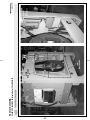
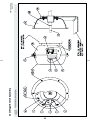
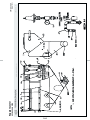
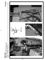
ÎFIGURE 17 (MSSM0201CE)
Î42" Staph-Guard®
ldler Shaft
Grease Fitting
ÎFIGURE 14 (MSSM0201CE)
ÎHandwheel Screw
(42" Divided Cylinder and Staph-Guard® only)
ÎFIGURE 18 (MSSM0201CE)
Î60" and 72" Staph-Guard® Idler Shaft
and Disc Brake Grease Fittings
(60" shown)
ÎFIGURE 15 (MSSM0201CE)
ÎTypical Door Hinge
ÎFIGURE 19 (MSSM0201CE)
ÎTypical Jackshaft
Grease Fittings
( 52" machine shown)
ÎFIGURE 16 (MSSM0201CE)
ÎHandwheel Stop
(42" Divided Cylinder and Staph-Guard® only)
30
ÎFIGURE 20 (MSSM0201CE)
ÎTilt Wheels
(42"and 48" tilt machines only)
Ï
0.12 ounces (3.54 grams),
two strokes at each location
0.06 ounces (1.77 grams),
one stroke at one location
0.31 ounces (8.85 grams),
five strokes at two locations
0.12 ounces (3.54 grams),
two strokes at one location
0.12 ounces (3.54 grams)
two strokes at two locations
0.12 ounces (3.54 grams),
two strokes at each locations
Door hinges
• Grease fittings
FIGURE 15
Handwheel stop
(42" Divided Cylinder and StaphGuard® )
• Grease fitting
FIGURE 16
Idler shaft
(Staph-Guard® only)
• Grease fittings
FIGURES 17 and 18
Disc brake
(60" and 72" Staph-Guard® only)
• Grease fittings
FIGURE 18
Jackshaft
(if equipped)
• Grease fittings
FIGURE 19
NOTES 5 and 6
Tilt wheels
(42", 48", and 72" Tilt Models )
• Grease fittings
FIGURE 20
Action
Three drops of light machine
oil
Component
Monthly
Handwheel screw
(see NOTE 4) (42" Divided Cylinder and StaphGuard® )
• Screw thread
FIGURE 14
Frequency
Monthly Maintenance Items
31
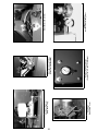
ÎFIGURE 24 (MSSM0201CE)
ÎDisk Brake
(Staph-Guard® only)
Î IGURE 21 (MSSM0201CE)
F
ÎDisk Brake Reservoir
(Staph-Guard® only)
ÎFIGURE 25 (MSSM0201CE)
Î ydraulic Tilt Pressure Gauge
H
(On rear of 42", 48", and 72" tilt models)
ÎFIGURE 22 (MSSM0201CE)
Î rake Band Grease Fittings
B
(60044 and 72044WP2/WP3)
Brake band
grease fittings
ÎFIGURE 26 (MSSM0201CE)
ÎDoor Seal Pressure Regulator
ÎFIGURE 23 (MSSM0201CE)
ÎBrake Shoes (all machines)
ÏQuarterly Maintenance Items
Frequency
Component
Action
Quarterly Brake Components
• Disk brake reservoir
(60" and 72" Staph-Guard® only)
FIGURE 21
Check level, refill as required
(Always use fresh fluid from a sealed container)
• Brake band grease fittings
(60044 and 72044 WP2/WP3 only)
FIGURE 22
0.06 ounces (1.77 grams),
one stroke at two locations. Do not allow grease
to drip on brake surfaces.
• Brake shoes
FIGURE 23
Check for wear, adjust or replace as required.
• Disc brake pads
(60" and 72" Staph-Guard®only)
FIGURE 24
Check for wear, replace as required
Hydro-Cushions®
FIGURES 2 and 3
Check oil level, add as necessary
Inspect washer, replace as necessary
Motors
FIGURE 12
NOTES 8 and 9
See “BALDOR MOTOR MAINTENANCE...,”
MSSM0274AE in this manual.
Hydraulic tilt
pressure gauge
FIGURE 25
Check pressure while machine is returning from
a tilted position
• 42" Open pocket
800 PSI (55 Bar)
• 48" Open pocket
900 PSI (62 Bar)
• 72" Open pocket
1000 PSI (69 Bar)
Door seal
pressure regulator
FIGURE 26
Check settings with machine in bare manual and
clockwise wash rotation. See instructions for
operating individual outputs in the reference
manual.
• 42" and 48" Open pocket
48 - 50 PSI (3.37 - 3.51Kg/cm2)
• 60" and 72" Rapid load
25 - 28 PSI (1.76 - 1.97 Kg/cm2)
• 60" and 72" Staph-Guard®
18 - 20 PSI (1.27 - 1.41 Kg/cm2)
NOTE 8: If motor manufacturer’s instructions conflict with manual section, follow nameplate instructions.
motors are warrantied by their manufacturers, not by Milnor®.
NOTE 9: Pump grease slowly with relief ports open. Do not over-lubricate.
32
33
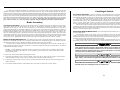
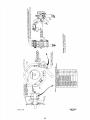
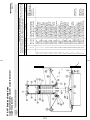
ÎFIGURE 28 (MSSM0201CE)
ÎPush Back and Forward Hydraulic System
Gauges and Regulators
(42", 48", and 72" Tilt Models)
ÎFIGURE 30 (MSSM0201CE)
Î hell Door Recirculation Hose
S
(48" dye machine only - cover removed for clarity)
Î IGURE 27 (MSSM0201CE)
F
ÎTypical Gear Reducer Fill and Drain
ÎFIGURE 29 (MSSM0201CE)
Î ush-Down Control Valve
P
(72" Rapid load and Staph-Guard® only)
Component
Hydraulic system
FIGURE 28
Hydro-Cushions®
FIGURE 2
Gear reducer
FIGURE 27
Component
Change oil
Change oil
Change oil and clean magnetic
plug (if so equipped)
Action
ÏAnnual or Less Frequent Maintenance Items
NOTE 11:Adjust push-down control valves so that machine moves down evenly,
and all push-down sockets meet simultaneously. If the back of the machine
comes down first, close the valve slowly. If the front comes down first, open
the valve.
NOTE 10:52" and 72" machines are not equipped with a tilt pressure regulator
or gauge.
Every 2
years
Annual
Frequency
Observe operation and adjust if
required
Push-down control valves
(72" Rapid load and StaphGuard®)
FIGURE 29 and NOTE 11
Replace hose
Check pressure in a “wash step”
30 PSI (2.11Kg/cm2)
• Tilt position pressure regulator
and gauge
Recirculation
(48" dye models only)
FIGURE 30
Check pressure in a “wash step”
3 - 5 PSI (.21- 0.35 Kg/cm2)
Check oil level, refill as required
0.12 ounces (3.54 grams),
two strokes at one location
Action
• Down position pressure
gauge and regulator
Push Back and Forward System
FIGURE 28 and NOTE 10
Gear reducer
FIGURE 27
Semi-Annual Main bearings and seals
• 48" Seal grease fittings
FIGURE 11
Frequency
ÏSemi-Annual Maintenance Items
34
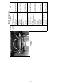
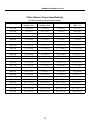
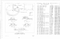
52038WP1/WTL/WTN
64046ExN
72046ExN
72058JxN
Divided Cylinder Machines
42031 - 44 WP2/3
42031 - 44 SP2/3
60044 SP2/3
72044 SP2/3
30015, 20, 22, C, S, and M
3022F8J
36021Q4x, 36026Q4x
36021BWP
36021Q6x, 36026Q6x,
42024Q4x, 42026Q6x
36030Fxx
42032Fxx
42026QHP
48032BHP/BTL/BTN
48036QHP/QTL/QTN
Open Pocket Machines
Bearing housings
EPLF 2
EPLF 2
220
30
Gear reducers
220
220
220
Isolators
1030
1030
220
®
Hydro-Cushions
1030 EPLF 2
1030
220
Motors
EPLF 2
Commutator cam
Wells
Balancing mechanism
1540
DOT 3
DOT 3
DOT 3
Disc brake
(if so equipped)
Washer-Extractors
68
1030
Hydraulic tilt mechanism
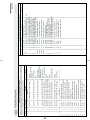
The following are lubricants used in Milnor® machines. Always refer to the preventive maintenance instructions for
specific lubricating instructions. Consult lubricant manufacturer to verify equivalence before using a substitute. Mixing
different base greases can cause bearing and seal damage.
Door EPLF 2
Door EPLF 2
Door latches
Bearing housings
EPLF 2
Gear reducer
EPLF 2
Drive motors
ÏOils
634
1030
220
32
220
Disc brake
Hydraulic mechanisms
68 DOT 3
Drive/Support rollers
Guide rollers
23
Blower shaft bearings
Door
EPLF 2
EP2
FL
R
Wells
SRI
=
=
=
=
=
=
=
EP2
EPLF 2 EP2
T32 EPLF 2 EPLF 2
Mist oiler
DOT 3 = NAPA Super Heavy Duty Brake Fluid DOT 3
23
= Shell Tellus® 23
30
= High quality SAE 30, 40, or 50 weight motor oil
(non-detergent, if available)
32
= Shell Tellus® 32
T32
= Shell Turbo® T32
68
= Shell Tellus® 68
220
= Shell Morlina® 220
630
= Valvoline Special Moly® EP 630
634
= Mobile SHC® 634 Oil
1030
= Shell Rotella T® 10W30
1540
= Shell Rotella T® HD 15W40
Dryvac
Shuttle &
Conveyor
Dryer
Press
Single Stage
Press
42032M9E
42032M7E
CBW®
®
Hydro-Cushions
LUBRICANTS FOR MILNOR® MACHINES
È
Other grease points
CBW® , Extractor, Press, Shuttles, Conveyors, and Dryvacs
Press pressure pump
R
R
SRI
Inflatable rib couplings
FL
Shuttle chain
EPLF 2
Doorease® Stick lubricant
Shell Alvania® EP-LF Type 2
Shell Darina® EP-2
Recol Food Lubricant
Shell Dolium® R
Wells CL200 Cam Lubricant
Chevron SRI oil
ÏGreases
630
Blower motors
MSSM0132AE/9903AV (1 of 1)
All other grease points
21<4?B=?D?B=19>D5>1>35
<BB<!(&"
0E
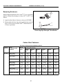
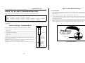
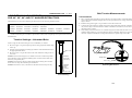
Most of the information in this document is taken from the Baldor Electric Company Instruction,
Operation, and Maintenance Manual, and provides a means of more accurately determining motor
lubrication requirements based on local conditions.
7U^UbQ\=QY^dU^Q^SU
Inspect, clean, and test motors at regular intervals— approximately every 500 operating hours
or every three months, whichever comes first. Lubricate motors at the intervals determined herein. Keep
accurate maintenance records.
!
41>75B* 5\USdb_SedY_^ Q^T 5\USdbYSQ\ 2eb^ 8QjQbTc
2^]cPRc fXcW WXVW e^[cPVT fX[[ T[TRca^RdcT ^a Qda] h^d ?^fTa bfXcRWTb ^] cWT
\PRWX]T P]S cWT R^]ca^[ Q^g S^ ]^c T[X\X]PcT cWTbT WPiPaSb 7XVW e^[cPVT Xb
_aTbT]c Pc cWT \PRWX]T d][Tbb cWT \PX] _^fTa Xb ^UU 4[TRcaXRP[ _^fTa RP] RPdbT
STPcW ^a bTeTaT X]Ydah
☞
☞
3^ ]^c bTaeXRT \PRWX]T d][Tbb `dP[XUXTS P]S PdcW^aXiTS
;^RZ >55 P]S cPV ^dc _^fTa Pc cWT fP[[ SXbR^]]TRc QTU^aT bTaeXRX]V ^a X]
PRR^aSP]RT fXcW UPRc^ah bTaeXRT _a^RTSdaTb
!
41>75B* 5^dQ^W\U Q^T 3becX 8QjQbT
2^]cPRc fXcW \^eX]V R^\_^]T]cb ]^a\P[[h Xb^[PcTS Qh VdPaSb R^eTab P]S
_P]T[b
RP]
T]cP]V[T
P]S
RadbW
h^da
[X\Qb
CWTbT
R^\_^]T]cb
Pdc^\PcXRP[[h
☞
3^
]^c
bTaeXRT
\PRWX]T
d][Tbb
`dP[XUXTS P]S PdcW^aXiTS
☞
;^RZ >55 P]S cPV ^dc _^fTa Pc cWT
fP[[ SXbR^]]TRc QTU^aT bTaeXRX]V ^a
X] PRR^aSP]RT fXcW UPRc^ah bTaeXRT
_a^RTSdaTb
3\UQ^—Keep the exterior of the motor free of dirt, oil,
grease, water, etc. Keep ventilation openings clear. Oily
vapor, paper pulp, textile lint, etc., can accumulate and
block ventilation, causing overheating and early motor
failure.
DUcd—Periodically, check the motor and winding
insulation integrity using a “megger.” Record the megger
readings and immediately investigate any significant drop
in insulation resistance. Check all electrical connectors to
be sure they are tight.
<eRbYSQdU—Determine the proper lubrication interval
for your motor as explained in “How to Determine
Lubrication Interval” in this section, and lubricate
accordingly.
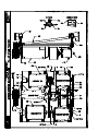
586DA4
=CC= "'$15
Di`YSQ\ =_d_b 4QdQ @\QdU
35
\^eT
21<4?B =?D?B =19>D5>1>35
=CC= "'$15)'#!1F"$
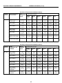
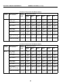
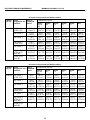
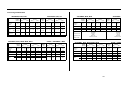
8_gd_4UdUb]Y^U<eRbYSQdY_^9^dUbfQ\—The useful life of antifriction bearing
grease can be estimated, based on service conditions, frame type, and motor rpm. An example of
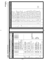
determining the correct lubrication interval is provided below.
Ex: A fan motor, operating at an ambient temperature of 109oF (43oC) in a moderately corrosive
atmosphere. The motor has a NEMA 286T/(IEC 180) frame and is rated at 1750 rpm.
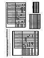
Table 1 classifies the service condition as “severe.”
Table 2 specifies a 0.5 service condition multiplier value for “severe” service condition.
Table 3 specifies 9500 hours as the recommended lubrication interval for frame sizes 254 to 286
(see nameplate), given standard service conditions.
Multiply .5 (service condition multiplier value) by 9500 hours (recommended lubrication interval)
= 4750 hours (calculated lubrication interval).
Table 4 shows that the amount of grease to be added is 0.32 ounces (9.1 grams).
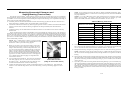
Table 1 — Determining the Service Condition
Severity of Service
Maximum Ambient
Temperature
Atmospheric
Contamination
Type of Bearing
Standard
104oF (40oC)
Clean, little corrosion
Deep groove ball
bearing
Severe
122oF (50oC)
Moderate dirt, corrosion
Ball thrust, Roller
Severe dirt, abrasive dust,
corrosion
All bearings
o
o
Extreme
>122 F (>50 C) or
Class H Insulation
(Note 1)
Low Temperature
-22oF (-30oC)
(Note 2)
Note 1: Special high temperature grease is recommended.
Note 2: Special low temperature grease is recommended.
Table 2 — Service Condition Multiplier Value
Operating
Condition
Multiplier
Standard
1.0
Severe
0.5
Extreme
0.1
36
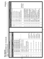
21<4?B =?D?B =19>D5>1>35
=CC= "'$15)'#!1F#$
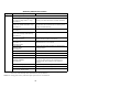
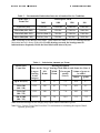
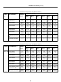
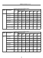
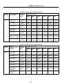
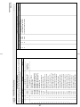
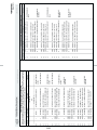
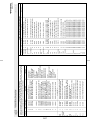
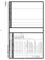
Table 3 — Recommended Lubrication Intervals at Standard Service Conditions
NEMA (IEC)
Frame Size
Rated Speed - RPM
3600
1800
1200
900
Up to 215 (132)
5500 Hrs.
12000 Hrs.
18000 Hrs.
22000 Hrs.
254 to 286 (160 - 180)
3600 Hrs.
9500 Hrs.
15000 Hrs.
18000 Hrs.
324 to 365 (200 - 225)
2200 Hrs.(Note 3)
7400 Hrs.
12000 Hrs.
15000 Hrs.
404 to 5000 (280 - 315)
2200 Hrs.(Note 3)
3500 Hrs.
7400 Hrs.
10500 Hrs.
Note 3: Bearings in 404 through 5000 frame, 2 pole motors are either 6313 or 6314 bearings and the
lubrication interval is shown in the table. If roller bearings are used, the bearings must be
lubricated more frequently. Divide the listed lubrication interval by two.
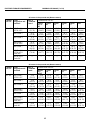
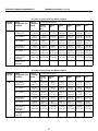
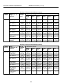
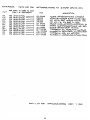
Table 4 — Lubrication Amounts per Frame
NEMA (IEC)
Frame Size
Bearing Description
These are the “Large” bearings (Shaft End) in each frame size (Note 4)
Largest
bearing
in size
category
OD
D mm
Width
B mm
Up to 215 (132)
6307
80
21
254 to 286
(160 - 180)
6311
120
324 to 365
(200 - 225)
6313
404 to 5000
(280 - 315)
NU322
Grease gun
strokes
(Note 5)
Volume of grease to
be added
ounces
grams
2.5
0.16
4.7
29
5.0
0.32
9.1
140
33
7.0
0.43
12.2
240
50
18.0
1.11
31.5
Note 4: Smaller bearings in size category may require reduced amounts of grease.
Note 5: See “Correct Grease Gun Procedures” for information on estimating the output of handoperated grease guns.
37
21<4?B =?D?B =19>D5>1>35
=CC= "'$15)'#!1F$$
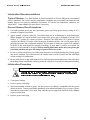
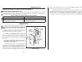
<eRbYSQdY_^BUS_]]U^TQdY_^c
Di`U_V7bUQcU—Use Shell Dolium R (factory installed) or Chevron SRI greases for standard
service conditions. The extreme and low temperature conditions are not normally encountered in the
laundry. However, for extreme conditions, use Darmex 707 and for low temperature conditions, use
Arrowshell 7. Contact Baldor for equivalents, if necessary.
3_bbUSd7bUQcU7e^@b_SUTebUc
Use hand-operated grease gun, not a pneumatic grease gun. Pump grease slowly, taking 10 to 12
seconds to complete each stroke.
Apply quantity of grease called for. Over-lubrication can be as damaging as under-lubrication.
Where quantities are stated in strokes, one stroke of the grease gun is assumed to provide .0624
fluid oz. (1.77 grams) (by volume) of grease. Therefore, one fluid ounce (28.3 grams) of grease
would be provided by 16 strokes of the grease gun. Determine the flow rate of your grease gun by
pumping one ounce into a calibrated container. If fewer than 16 strokes are required, all quantities
in strokes in the chart should be reduced accordingly. If more than 16 strokes are required, the
number of strokes should be increased. Before starting lubrication, make sure your grease gun
is working and that you get a full charge of grease with every stroke.
Do not over-lubricate motors. Over-lubrication of a motor can seriously damage it by forcing grease
into motor windings. Over-lubrication of the extract motor can force grease into the centrifugal
switch causing it to malfunction.
Do not allow grease to drip on the brake disk or clutch tire/drum during lubrication. This will reduce
the braking action considerably, and may permit the cylinder to creep while loading and unloading.
<eRbYSQdY_^@b_SUTebU
$
>?D935* =_d_b 4Q]QWU
C^ Pe^XS SP\PVT c^ \^c^a QTPaX]Vb VaTPbT \dbc QT ZT_c UaTT ^U SXac 5^a P]
TgcaT\T[h SXach T]eXa^]\T]c R^]cPRc h^da 1P[S^a SXbcaXQdc^a ^a P] PdcW^aXiTS
1P[S^a BTaeXRT 2T]cTa U^a PSSXcX^]P[ X]U^a\PcX^]
Clean grease fittings.
Remove grease outlet plug.
Add recommended amount of grease. Be sure grease to be added is compatible with the grease
already in motor. Consult your Baldor distributor or an authorized Baldor Service Center if grease
other than recommended is to be used. Stop when new grease appears at shaft hole in the endplate
or grease outlet plug.
Replace grease outlet plug.
38
MSSM0101CE/9906AV (1 of 19)
FASTENER TORQUE REQUIREMENTS
È
The specifications in this section apply to 1/4 inch and larger Unified National fine and coarse fasteners used on
Milnor® machines. This information is to be used only when torque specifications are not stated in the installation
or service instructions.
When tightening applicable fastener, abide by the following precautions:
1. Always use new fasteners. Replace bolts, nuts, flat washers, and lock washers in the order shown on the parts
drawing.
2. Unless otherwise specified, use:
Loctite® 271 threadlocker or equivalent for bearing
housing mounting bolts from one half to one inch in diameter.
•
•
Loctite® 277 threadlocker or equivalent for bearing
housing mounting bolts of one inch diameter or larger.
•
Loctite® 242 threadlocker for all other fasteners
requiring thread locking compound.
3. Use a torque wrench to assure proper tightness.
4. Never lubricate fasteners. The values specified herein are
maximum recommended torques and are calculated from
published ASTM and SAE data. Actual allowable torques
are application dependent and can vary for many reasons,
(joint types, gaskets, etc.). Use these values as a guide.
ÎFIGURE 1 (MSSM0101CE)
ÎFastener Grade Markings
5. Although FIGURE 1 depicts hex head bolts, the table applies to all head types.
Fasteners and Threadlocker
Ê
How Fasteners Loosen—Standard threaded fasteners are manufactured with a clearance fit for easy assemË
bly. With the fastener at the proper torque, 85% of the tightening torque is absorbed in the threads and under the
fastener head. The remaining 15% provides the friction that prevents the thread from slipping. When this friction is
overcome (by bending, thermal expansion, internal pressures, functional loads, or impact) the thread slips and loosens. Although higher torques reduce the likelihood of thread slippage, if slippage occurs, the threads unwind and
the fastener loosens. Once thread slippage begins, vibration increases the rate of loosening.
Preventing Loosening—The most effective way to prevent loosening of threaded parts is by proper appliË
cation of a threadlocking compound. Threadlocker provides lubrication during assembly, then hardens to seal the
threads against corrosion and provide resistance to thread slippage.
39
MSSM0101CE/9906AV (2 of 19)
Applying Threadlocker
Ê
NOTE: The following threadlocker information and
illustrations are excerpts from the Loctite® User’s
Guide and are used with permission.
For maximum strength, threadlocker must fill the thread
voids completely, as shown in FIGURE 2. Organic or petroleum solvent will remove excess uncured adhesive from
joints. Consult information below for the specific fastener application.
ÎFIGURE 2 (MSSM0101CE)
ÎCorrect Threadlocker Use
Bolts and Nuts—See FIGURE 3.
Ë
1. Clean all threads (bolt and nut) with cleaning solvent.
Apply here
2. Spray all threads with Loctite® Primer N. Allow to dry.
3. Insert bolt into through hole assembly.
4. Apply several drops of threadlocker onto bolt engagement area.
5. Assemble and tighten nut to correct torque for the
threadlocker.
Blind Holes—See FIGURE 4.
Ë
Not here
1. Clean all threads (bolt and nut) with cleaning solvent.
2. Spray all threads with Loctite® Primer N. Allow to dry.
ÎFIGURE 3 (MSSM0101CE)
ÎApplying Threadlocker to
Through Hole
3. Squirt several drops down female threads into bottom of
hole.
Onto
threads
4. Apply several drops to bolt.
5. Tighten to correct torque for the threadlocker.
Onto
threads
ÎFIGURE 4 (MSSM0101CE)
ÎApplying Threadlocker to Blind Holes
40
FASTENER TORQUE REQUIREMENTS
MSSM0101CE/9906AV (3 of 19)
Removing Fasteners
Ë
High strength threadlockers like Loctite® 271 (or equivalent)
may be weakened by heating to at least 500o F (260o C) as
follows.
1. Apply localized heat to fastener as shown in FIGURE 5.
2. Disassemble while hot. Once disassembled, the cured adhesive can be removed with Loctite® Gasket Remover
#790 (or equivalent).
ÎFIGURE 5 (MSSM0101CE)
ÎRemoving High Strength Threadlocker
ÏCarbon Steel Fasteners
Ï ll values in foot pounds and (Newton meters)
A
Nominal Grade
bolt size Designation and
Standard
1/4 - 20
Zinc or
If instructions call for :
Cadmium
Loctite
Loctite
Loctite
Plated
222 or
242
271
262
Loctite
272
Loctite
277
Bare
SAE Grade 1
ASTM A307
2.5
(3.39)
3.0
(4.06)
3.3
(4.47)
3.6
(4.88)
4.6
(6.23)
4.3
(5.83)
3.3
(4.47)
SAE Grade 2
4.1
(5.56)
4.9
(6.64)
5.5
(7.45)
6.0
(8.13)
7.7
(10.44)
7.1
(9.63)
5.5
(7.46)
SAE Grade 4
4.8
(6.50)
5.8
(7.86)
6.4
(8.67)
7.0
(9.49)
9.0
(12.20)
8.3
(11.25)
6.4
(8.67)
SAE Grade 5
ASTM A449
6.3
(8.54)
7.6
(10.3)
8.4
(11.38)
9.3
(12.60)
11.8
(15.99)
11.0
(14.91)
8.4
(11.39)
SAE Grade 7
7.9
(10.7)
9.4
(12.7)
10.5
(14.23)
11.5
(15.59)
14.7
(19.93)
13.6
(18.44)
10.5
(14.23)
SAE Grade 8
ASTM A354 Grade
BD
8.9
(12.0)
10.7
(14.5)
11.9
(16.13)
13.1
(17.76)
16.6
(22.50)
15.4
(20.88)
11.9
(16.13)
ASTM A354 Grade
BC
7.9
(10.7)
9.4
(12.7)
10.5
(14.23)
11.5
(15.59)
14.7
(19.93)
13.6
(18.44)
10.5
(14.23)
41
MSSM0101CE/9906AV (4 of 19)
ÏAll values in foot pounds and (Newton meters)
NomiGrade Designation
nal bolt and Standard
size
1/4 - 28
Zinc or If instructions call for :
Cadmium
Loctite
Loctite
Loctite
Plated
222 or
242
271
262
Loctite
272
Loctite
277
Bare
SAE Grade 1
ASTM A307
2.8
(3.80)
3.4
(4.61)
3.8
(5.15)
4.1
(5.56)
5.3
(7.18)
4.9
(6.64)
3.8
(5.15)
SAE Grade 2
4.7
(6.37)
5.6
(7.60)
6.3
(8.54)
6.9
(9.36)
8.8
(11.93)
8.1
(10.98)
6.3
(8.54)
SAE Grade 4
5.5
(7.46)
6.6
(8.95)
7.3
(9.90)
8.1
(10.98)
10.3
(13.96)
9.5
(12.88)
7.3
(9.90)
SAE Grade 5
ASTM A449
7.3
(9.90)
8.7
(11.80)
9.7
(13.15)
10.7
(14.50)
13.6
(18.44)
12.6
(17.08)
9.7
(13.15)
SAE Grade 7
8.9
(12.07)
10.7
(14.50)
11.9
(16.13)
13.1
(17.76)
16.6
(22.51)
15.4
(20.88)
11.9
(16.13)
SAE Grade 8
ASTM A354 Grade
BD
10.2
(13.83)
12.2
(16.54)
13.6
(18.44)
15.0
(20.34)
19.0
(25.76)
17.7
(23.99)
13.6
(18.44)
ASTM A354 Grade
BC
—
—
—
—
—
—
—
ÏAll values in foot pounds and (Newton meters)
Nominal Grade Designation
bolt size and Standard
Zinc or If instructions call for :
Cadmium
Loctite
Loctite
Loctite
Plated
222
242
271
or262
Loctite
272
Loctite
277
Bare
5/16 - 18 SAE Grade 1
ASTM A307
5.1
(6.91)
6.2
(8.40)
6.8
(9.22)
7.5
(10.17)
9.6
(13.02)
8.9
(12.07)
6.8
(9.22)
SAE Grade 2
8.5
(11.52)
10.2
(13.83)
11.3
(15.32)
12.5
(16.95)
15.9
(21.56)
14.7
(19.93)
11.3
(15.32)
SAE Grade 4
10.0
(13.56)
12.0
(16.27)
13.3
(18.03)
14.6
(19.79)
18.6
(25.22)
17.3
(23.46)
13.3
(18.03)
SAE Grade 5
ASTM A449
13.0
(17.63)
15.6
(21.15)
17.4
(23.60)
19.1
(25.90)
24.3
(32.95)
22.6
(30.64)
17.4
(23.60)
SAE Grade 7
16.1
(21.83)
19.3
(26.17)
21.5
(29.15)
23.6
(31.99)
30.1
(40.81)
27.9
(37.83)
21.5
(29.15)
SAE Grade 8 ASTM
A354 Grade BD
18.5
(25.08)
22.1
(29.96)
24.6
(33.35)
27.1
(36.74)
34.5
(46.78)
32.0
(43.39)
24.6
(33.35)
ASTM A354 Grade
BC
16.1
(21.83)
19.3
(26.17)
21.5
(29.15)
23.6
(31.99)
30.1
(40.81)
27.9
(37.83)
21.5
(29.15)
42
FASTENER TORQUE REQUIREMENTS
MSSM0101CE/9906AV (5 of 19)
ÏAll values in foot pounds and (Newton meters)
Nominal Grade Designation Zinc
If instructions call for :
bolt size and Standard
orCadmium
Loctite Loctite Loctite
Plated
222 or
242
271
262
Loctite
272
Loctite
277
Bare
5/16 - 24 SAE Grade 1
ASTM A307
5.6
(7.59)
6.7
(9.08)
7.4
(10.03)
8.2
(11.12)
10.4
(14.10)
9.6
(13.01)
7.4
(10.03)
SAE Grade 2
9.4
(12.74)
11.3
(15.32)
12.5
(16.94)
13.8
(18.71)
17.5
(23.73)
16.3
(22.09)
12.5
(16.94)
SAE Grade 4
11.0
(14.91)
13.2
(17.90)
14.6
(19.79)
16.1
(21.83)
20.5
(27.79)
19.0
(25.76)
14.6
(19.79)
SAE Grade 5
ASTM A449
14.4
(19.52)
17.2
(23.32)
19.1
(25.90)
21.1
(28.60)
26.8
(36.35)
24.9
(33.76)
19.1
(25.90)
SAE Grade 7
17.9
(24.27)
21.4
(29.01)
23.8
(32.27)
26.2
(35.52)
33.4
(45.28)
31.0
(42.03)
23.8
(32.27)
SAE Grade 8
ASTM A354 Grade
BD
20.4
(27.66)
24.4
(33.08)
27.1
(36.74)
29.9
(40.54)
38.0
(51.52)
35.3
(47.86)
27.1
(36.74)
ASTM A354 Grade
BC
—
—
—
—
—
—
—
ÏAll values in foot pounds and (Newton meters)
Nominal Grade
bolt size Designation and
Standard
3/8 - 16
Zinc or
Cadmium
Plated
If instructions call for :
Loctite
222 or
262
Loctite
242
Loctite
271
Loctite
272
Loctite
277
Bare
SAE Grade 1
ASTM A307
9.0
(12.20)
10.8
(14.64)
12.0
(16.27)
13.1
(17.76)
16.7
(22.64)
15.5
(21.01)
12.0
(16.27)
SAE Grade 2
14.9
(20.20)
17.9
(24.27)
19.9
(26.98)
21.9
(29.69)
27.9
(37.83)
25.9
(35.11)
19.9
(26.98)
SAE Grade 4
17.8
(24.13)
21.3
(28.88)
23.7
(32.13)
26.0
(35.25)
33.1
(44.87)
30.8
(41.76)
23.7
(32.13)
SAE Grade 5
ASTM A449
23.2
(31.45)
27.8
(37.69)
30.9
(41.89)
34.0
(46.09)
43.3
(58.70)
40.2
(54.50)
30.9
(41.89)
SAE Grade 7
28.7
(38.91)
34.4
(46.64)
38.2
(51.79)
42.0
(56.94)
53.5
(72.54)
49.7
(67.39)
38.2
(51.79)
SAE Grade 8
ASTM A354
Grade BD
32.7
(44.33)
39.2
(53.15)
43.6
(59.11)
48.0
(65.08)
61.0
(82.70)
56.7
(76.87)
43.6
(59.11)
ASTM A354
Grade BC
28.7
(38.91)
34.4
(46.64)
38.2
(51.79)
42.0
(56.94)
53.5
(72.54)
49.7
(67.39)
38.2
(51.79)
43
MSSM0101CE/9906AV (6 of 19)
ÏAll values in foot pounds and (Newton meters)
Nominal Grade Designation
bolt size and Standard
3/8 - 24
Zinc or
If instructions call for :
Cadmium
Loctite
Loctite
Loctite
Plated
222 or
242
271
262
Loctite
272
Loctite
277
Bare
SAE Grade 1
ASTM A307
10.2
(13.83)
12.2
(16.54)
13.6
(18.44)
15.0
(20.33)
19.0
(25.76)
17.7
(24.00)
13.6
(18.44)
SAE Grade 2
16.9
(22.91)
20.3
(27.52)
22.5
(30.52)
24.8
(33.62)
31.5
(42.70)
29.3
(39.73)
22.5
(30.50)
SAE Grade 4
20.0
(27.11)
24.0
(32.54)
26.7
(36.20)
29.4
(39.86)
37.4
(50.70)
34.7
(47.04)
26.7
(36.20)
SAE Grade 5
ASTM A449
26.2
(35.52)
31.4
(42.57)
34.9
(47.32)
38.4
(52.06)
48.9
(66.30)
45.4
(61.55)
34.9
(47.32)
SAE Grade 7
32.3
(43.79)
38.8
(52.60)
43.1
(58.44)
47.4
(64.26)
60.4
(81.89)
56.1
(76.06)
43.1
(58.43)
SAE Grade 8
ASTM A354 Grade
BD
36.9
(50.02)
44.3
(60.06)
49.2
(66.70)
54.1
(73.35)
68.9
(93.41)
64.0
(86.77)
49.2
(66.70)
ASTM A354 Grade
BC
—
—
—
—
—
—
—
ÏAll values in foot pounds and (Newton meters)
Nominal Grade Designation Zinc or
If instructions call for :
bolt size and Standard
CadmiumLoctite
Loctite
Loctite
Plated
222 or
242
271
262
Loctite
272
Loctite
277
Bare
7/16 - 14 SAE Grade 1
ASTM A307
14.0
(18.98)
17.0
(23.04)
19.14
(25.95)
21.0
(28.47)
27.0
(36.60)
25.0
(33.89)
19.0
(25.76)
SAE Grade 2
24.0
(32.54)
28.8
(39.05)
32.0
(43.39)
35.2
(47.72)
44.8
(60.74)
41.6
(56.40)
32.0
(43.39)
SAE Grade 4
28.3
(38.37)
34.0
(46.10)
37.7
(51.11)
41.5
(56.27)
52.8
(71.59)
49.1
(66.57)
37.7
(51.11)
SAE Grade 5
ASTM A449
37.1
(50.30)
44.5
(60.33)
49.5
(67.11)
54.4
(73.76)
69.3
(93.96)
64.3
(87.18)
49.5
(67.11)
SAE Grade 7
45.9
(62.23)
55.1
(74.70)
61.3
(83.11)
67.4
(91.38)
85.8
(116.33)
79.6
(107.92)
61.3
(83.11)
SAE Grade 8
ASTM A354 Grade
BD
52.5
(71.18)
63.0
(85.41)
70.0
(94.90)
77.0
(104.40)
98.0
(132.87)
91.0
(123.38)
70.0
(94.90)
ASTM A354 Grade
BC
45.7
(61.96)
54.9
(74.43)
61.0
(82.70)
67.1
(90.97)
85.4
(115.79)
79.3
(107.52)
61.0
(82.70)
44
FASTENER TORQUE REQUIREMENTS
MSSM0101CE/9906AV (7 of 19)
ÏAll values in foot pounds and (Newton meters)
Nominal Grade
bolt size Designation and
Standard
Zinc or
Cadmium
Plated
If instructions call for :
Loctite
222 or
262
Loctite
242
Loctite
271
Loctite
272
Loctite
277
Bare
7/16 - 20 SAE Grade 1
ASTM A307
16.0
(21.70)
19.2
(26.03)
21.3
(28.88)
23.5
(31.86)
29.9
(40.54)
27.7
(37.56)
21.3
(28.88)
SAE Grade 2
26.9
(36.48)
32.2
(43.66)
35.8
(48.54)
39.4
(53.42)
50.1
(67.93)
46.6
(63.18)
35.8
(48.54)
SAE Grade 4
31.6
(42.84)
37.9
(51.39)
42.1
(57.08)
46.3
(62.77)
59.0
(79.99)
54.7
(74.16)
42.1
(57.08)
SAE Grade 5
ASTM A449
41.4
(56.13)
49.7
(67.38)
55.2
(74.84)
60.8
(82.43)
77.3
(104.80)
71.8
(97.35)
55.2
(74.84)
SAE Grade 7
51.3
(69.55)
61.5
(83.38)
68.4
(92.74)
75.2
(101.96)
95.7
(129.75)
88.9
(120.53)
68.4
(92.74)
SAE Grade 8
ASTM A354
Grade BD
58.2
(78.90)
69.9
(94.77)
77.7
(105.35)
85.4
(115.78)
108.7
(147.37)
101.0
(136.94)
77.7
(105.35)
ASTM A354
Grade BC
—
—
—
—
—
—
—
ÏAll values in foot pounds and (Newton meters)
Nominal Grade
bolt size Designation and
Standard
1/2 - 13
Zinc or
Cadmium
Plated
If instructions call for :
Loctite
222
or262
Loctite
242
Loctite
271
Loctite
272
Loctite
277
Bare
SAE Grade 1
ASTM A307
22.0
(29.83)
26.0
(35.25)
29.38
(39.83)
32.0
(43.39)
41.0
(55.59)
38.0
(51.52)
29.0
(39.32)
SAE Grade 2
36.6
(49.62)
43.9
(59.52)
48.8
(66.16)
53.6
(72.67)
68.3
(92.60)
63.4
(85.96)
48.8
(66.16)
SAE Grade 4
43.1
(58.44)
51.8
(70.23)
57.5
(77.96)
63.3
(85.82)
80.5
(109.14)
74.8
(101.42)
57.5
(77.96)
SAE Grade 5
ASTM A449
56.7
(76.87)
68.1
(92.33)
75.6
(102.5)
83.2
(112.80)
105.9
(143.58)
98.3
(133.27)
75.6
(102.50)
SAE Grade 7
69.8
(94.64)
83.8
(113.62)
93.1
(126.23)
102.4
(138.84)
130.4
(176.80)
121.1
(164.19)
93.1
(126.23)
SAE Grade 8
ASTM A354
Grade BD
79.7
(108.05)
95.6
(129.62)
106.3
(144.12)
116.9
(158.50)
148.8
(201.75)
138.1
(187.24)
106.3
(144.12)
ASTM A354
Grade BC
69.8
(94.64)
83.8
(113.62)
93.1
(126.23)
102.4
(138.84)
130.4
(176.80)
121.1
(164.19)
93.1
(126.23)
45
MSSM0101CE/9906AV (8 of 19)
ÏAll values in foot pounds and (Newton meters)
Nominal Standard and
Zinc or
bolt size Grade Designation Cadmium
Plated
1/2 - 20
If instructions call for :
Loctite
222 or
262
Loctite
242
Loctite
271
Loctite
272
Loctite
277
Bare
SAE Grade 1
ASTM A307
24.8
(33.62)
29.8
(40.40)
33.1
(44.88)
36.4
(49.35)
46.4
(62.91)
43.1
(58.44)
33.1
(44.88)
SAE Grade 2
41.3
(56.00)
49.5
(67.11)
55.0
(74.57)
60.5
(82.02)
77.0
(104.40)
71.5
(96.94)
55.0
(74.57)
SAE Grade 4
48.8
(66.16)
58.5
(79.32)
65.0
(88.13)
71.5
(96.94)
91.0
(123.38)
84.5
(114.57)
65.0
(88.13)
SAE Grade 5
ASTM A449
63.8
(86.50)
76.5
(103.72)
85.0
(115.24)
93.5
(126.77)
119.0
(161.34)
110.5
(149.82)
85.0
(115.24)
SAE Grade 7
78.8
(106.84)
94.5
(128.12)
105.0
(142.36)
115.5
(156.60)
147.0
(199.30)
136.5
(185.07)
105.0
(142.36)
SAE Grade 8
ASTM A354 Grade
BD
90.0
(122.02)
108.0
(146.43)
120.0
(162.70)
132.0
(179.00)
168.0
(277.78)
156.0
(211.51)
120.0
(162.70)
ASTM A354 Grade
BC
—
—
—
—
—
—
—
ÏAll values in foot pounds and (Newton meters)
Nominal Grade Designation Zinc or
bolt size and Standard
Cadmium
Plated
If instructions call for :
Loctite
222
or 262
Loctite
242
Loctite
271
Loctite
272
Loctite
277
Bare
9/16 - 12 SAE Grade 1
ASTM A307
32.0
(43.39)
38.0
(51.52)
42.19
(57.20)
46.0
(62.37)
59.0
(80.00)
55.0
(74.57)
42
(56.94)
SAE Grade 2
52.7
(71.45)
63.3
(85.82)
70.3
(95.31)
77.3
(104.80)
98.4
(133.41)
91.4
(123.92)
70.3
(95.31)
SAE Grade 4
62.2
(84.33)
74.7
(101.28)
83.0
(112.53)
91.3
(123.79)
116.2
(157.55)
107.9
(146.30)
83.0
(112.53)
SAE Grade 5
ASTM A449
81.7
(110.77)
98.1
(133.00)
109.0
(147.78)
119.9
(162.56)
152.6
(206.90)
141.7
(192.17)
109.0
(147.78)
SAE Grade 7
100.7
(136.53)
120.9
(163.92)
134.3
(182.09)
147.7
(200.25)
188.0
(254.89)
174.6
(236.73)
134.3
(182.09)
SAE Grade 8
ASTM A354 Grade
BD
115.0
(155.92)
138.0
(187.10)
153.3
(207.85)
168.6
(228.59)
214.6
(290.96)
199.3
(270.21)
153.3
(207.85)
ASTM A354 Grade
BC
100.7
(136.53)
120.9
(163.92)
134.3
(182.09)
147.7
(200.25)
188.0
(254.89)
174.6
(236.73)
134.3
(182.09)
46
FASTENER TORQUE REQUIREMENTS
MSSM0101CE/9906AV (9 of 19)
ÏAll values in foot pounds and (Newton meters)
Nominal Grade Designation
bolt size and Standard
Zinc or If instructions call for:
Cadmium
Loctite
Loctite
Loctite
Plated
222 or
242
271
262
Loctite
272
Loctite
277
Bare
9/16 - 18 SAE Grade 1
ASTM A307
35.3
(47.86)
42.4
(57.49)
47.1
(63.86)
51.8
(70.23)
66.0
(89.48)
61.2
(82.98)
47.1
(63.86)
SAE Grade 2
59.1
(80.13)
70.9
(96.13)
78.8
(106.84)
86.6
(117.41)
110.3
(149.55)
102.4
(138.84)
78.8
(106.84)
SAE Grade 4
69.6
(94.36)
83.5
(113.21)
92.8
(125.82)
102.1
(138.43)
129.9
(176.12)
120.7
(163.65)
92.8
(125.85)
SAE Grade 5
ASTM A449
91.2
(123.65)
109.5
(148.46)
121.6
(164.87)
133.8
(181.40)
170.3
(230.90)
158.1
(214.36)
121.6
(164.87)
SAE Grade 7
112.3
(152.26)
134.8
(182.76)
149.8
(203.10)
164.7
(223.30)
209.7
(284.32)
194.7
(263.98)
149.8
(203.10)
SAE Grade 8
ASTM A354 Grade
BD
128.7
(174.61)
154.4
(209.34)
171.6
(232.66)
188.7
(255.84)
240.2
(325.67)
223.0
(302.35)
171.6
(232.66)
ASTM A354 Grade
BC
—
—
—
—
—
—
—
ÏAll values in foot pounds and (Newton meters)
Nominal Grade Designation
bolt size and Standard
5/8 - 11
Zinc or If instructions call for:
Cadmium
Loctite
Loctite
Loctite
Plated
222 or
242
271
262
Loctite
272
Loctite
277
Bare
SAE Grade 1
ASTM A307
44
(59.66)
52
(70.50)
58.2
(78.90)
64
(86.77)
81
(109.82)
76
(103.04)
58
(78.64)
SAE Grade 2
72.7
(98.57)
87.2
(118.23)
96.9
(131.38)
106.6
(144.53)
135.6
(183.85)
125.9
(170.70)
96.9
(131.38)
SAE Grade 4
86.1
(116.74)
103.4
(140.19)
114.8
(155.65)
126.3
(171.24)
160.8
(218.02)
149.3
(202.42)
114.8
(155.65)
SAE Grade 5
ASTM A449
112.5
(152.53)
135.0
(183.04)
150.0
(203.37)
165.0
(223.71)
210.0
(284.72)
195.0
(264.38)
150.0
(203.37)
SAE Grade 7
138.9
(188.32)
166.6
(225.88)
185.2
(251.10)
203.7
(276.18)
259.2
(351.43)
240.7
(326.35)
185.2
(251.10)
SAE Grade 8
ASTM A354 Grade
BD
158.8
(215.30)
190.5
(258.28)
211.7
(287.03)
232.9
(315.77)
296.4
(401.86)
275.2
(373.12)
211.7
(287.03)
ASTM A354 Grade
BC
139.2
(188.73)
167.0
(226.42)
185.5
(251.50)
204.1
(276.72)
259.8
(352.24)
241.2
(327.02)
185.5
(251.50)
47
MSSM0101CE/9906AV (10 of 19)
ÏAll values in foot pounds and (Newton meters)
Nominal Grade Designation
bolt size and Standard
5/8 - 18
Zinc or If instructions call for:
Cadmium
Loctite
Loctite
Loctite
Plated
222 or
242
271
262
Loctite
272
Loctite
277
Bare
SAE Grade 1
ASTM A307
49.5
(67.11)
59.4
(80.54)
66.0
(89.48)
72.6
(98.43)
92.4
(125.27)
85.8
(116.33)
66.0
(89.48)
SAE Grade 2
82.6
(112.00)
99.1
(134.36)
110.2
(149.41)
121.2
(164.33)
154.2
(209.07)
143.2
(194.15)
110.2
(149.41)
SAE Grade 4
97.3
(131.92)
116.7
(158.22)
129.7
(175.85)
142.7
(193.48)
181.6
(246.22)
168.6
(228.59)
129.7
(175.85)
SAE Grade 5
ASTM A449
127.7
(173.14)
153.3
(207.85)
170.3
(230.90)
187.3
(253.95)
238.4
(323.23)
221.4
(300.18)
170.3
(230.90)
SAE Grade 7
157.6
(213.68)
189.1
(256.39)
210.2
(285.00)
231.2
(313.47)
294.2
(398.88)
273.2
(370.41)
210.2
(285.00)
SAE Grade 8
ASTM A354 Grade
BD
179.9
(243.91)
215.9
(292.72)
239.8
(325.13)
263.8
(357.66)
335.8
(455.28)
311.8
(422.74)
239.8
(325.13)
ASTM A354 Grade
BC
—
—
—
—
—
—
—
ÏAll values in foot pounds and (Newton meters)
Nominal Grade Designation
bolt size and Standard
3/4 - 10
Zinc or If instructions call for:
Cadmium
Loctite
Loctite
Loctite
Plated
222 or
242
271
262
Loctite
272
Loctite
277
Bare
SAE Grade 1
ASTM A307
77
(104.40)
93
(126.09)
103.1
(139.78)
113
(153.20)
144
(195.24)
134
(181.68)
103
(139.65)
SAE Grade 2
129.4
(175.44)
155.3
(210.55)
172.5
(233.88)
189.8
(257.33)
241.5
(327.43)
224.3
(304.11)
172.5
(233.88)
SAE Grade 4
152.6
(206.90)
183.1
(248.25)
203.4
(275.77)
223.8
(303.43)
284.8
(386.14)
264.5
(358.61)
203.4
(275.77)
SAE Grade 5
ASTM A449
199.7
(270.76)
239.6
(324.85)
266.3
(361.05)
292.9
(397.12)
372.8
(505.45)
346.1
(469.25)
266.3
(361.05)
SAE Grade 7
246.8
(334.62)
296.2
(401.60)
329.1
(446.20)
362.0
(355.22)
460.7
(624.63)
427.8
(580.02)
329.1
(446.20)
SAE Grade 8
ASTM A354 Grade
BD
282.0
(382.34)
338.3
(458.67)
375.9
(509.65)
413.5
(560.63)
526.3
(713.57)
488.7
(662.59)
375.9
(509.65)
ASTM A354 Grade
BC
246.4
(334.07)
295.7
(400.92)
328.6
(445.53)
361.5
(490.13)
460.0
(623.67)
427.2
(579.20)
328.6
(445.53)
48
FASTENER TORQUE REQUIREMENTS
MSSM0101CE/9906AV (11 of 19)
ÏAll values in foot pounds and (Newton meters)
Nominal Grade Designation
bolt size and Standard
3/4 - 16
Zinc or If instructions call for:
Cadmium
Loctite
Loctite
Loctite
Plated
222 or
242
271
262
Loctite
272
Loctite
277
Bare
SAE Grade 1
ASTM A307
86.5
(117.28)
103.8
(140.73)
115.3
(156.33)
126.8
(171.92)
161.4
(218.83)
149.9
(203.24)
115.3
(156.33)
SAE Grade 2
144.1
(195.37)
173.0
(234.56)
192.2
(260.59)
211.4
(286.62)
269.1
(364.85)
249.8
(338.68)
192.2
(260.59)
SAE Grade 4
170.2
(230.76)
204.2
(276.86)
226.9
(307.64)
249.6
(338.41)
317.6
(430.61)
294.9
(399.15)
226.9
(307.64)
SAE Grade 5
ASTM A449
222.9
(302.21)
267.5
(362.68)
297.2
(402.95)
326.9
(443.22)
416.1
(564.16)
386.3
(523.75)
297.2
(402.95)
SAE Grade 7
275.6
(373.66)
330.8
(448.50)
367.5
(498.26)
404.3
(548.16)
514.5
(697.57)
477.8
(647.81)
367.5
(498.26)
SAE Grade 8
ASTM A354 Grade
BD
315.0
(427.08)
378.0
(512.50)
420.0
(569.44)
462.0
(626.39)
588.0
(797.22)
546.0
(740.28)
420.0
(569.44)
ASTM A354 Grade
BC
—
—
—
—
—
—
—
ÏAll values in foot pounds and (Newton meters)
Nominal Grade Designation
bolt size and Standard
7/8 - 9
Zinc or If instructions call for:
Cadmium
Loctite
Loctite
Loctite
Plated
222 or
242
271
262
Loctite
272
Loctite
277
Bare
SAE Grade 1
ASTM A307
124.7
(169.07)
149.6
(202.83)
166.3
(225.47)
182.9
(247.98)
232.8
(315.63)
216.1
(293.0)
166.3
(225.47)
SAE Grade 2
124.7
(169.07)
149.6
(202.83)
166.3
(225.47)
182.9
(247.98)
232.8
(315.63)
216.1
(293.00)
166.3
(255.47)
SAE Grade 4
246.1
(333.67)
295.3
(400.37)
328.1
(444.84)
360.9
(489.32)
459.4
(622.86)
426.6
(578.40)
328.1
(444.84)
SAE Grade 5
ASTM A449
322.4
(437.11)
386.9
(524.57)
429.8
(582.73)
472.8
(641.03)
601.8
(815.93)
558.8
(757.63)
429.8
(582.73)
SAE Grade 7
397.9
(539.48)
477.4
(647.27)
530.5
(719.26)
583.5
742.7
689.6
(791.12) (1007.00) (935.00)
530.5
(719.26)
SAE Grade 8
ASTM A354 Grade
BD
454.5
(616.22)
545.3
(739.33)
605.9
(821.49)
666.5
848.3
787.7
605.9
(903.65) (1150.14) (1067.98) (821.49)
ASTM A354 Grade
BC
397.9
(539.48)
477.4
(647.27)
530.5
(719.26)
583.5
742.7
689.6
(791.12) (1007.00) (935.00)
49
530.5
(719.26)
MSSM0101CE/9906AV (12 of 19)
ÏAll values in foot pounds and (Newton meters)
Nominal Grade Designation
bolt size and Standard
7/8 - 14
Zinc or If instructions call for:
Cadmium
Loctite
Loctite
Loctite
Plated
222 or
242
271
262
Loctite
272
Loctite
277
Bare
SAE Grade 1
ASTM A307
137.8
(186.83)
165.4
(224.25)
183.8
(249.20)
202.1
(274.01)
257.3
(348.85)
238.9
(323.90)
183.8
(249.20)
SAE Grade 2
137.8
(186.83)
165.4
(224.25)
183.8
(249.20)
202.1
(274.01)
257.3
(348.85)
238.9
(323.90)
183.8
(249.20)
SAE Grade 4
271.5
(368.11)
325.8
(441.73)
362.0
(490.80)
398.2
(539.89)
506.8
(687.13)
470.6
(638.05)
362.0
(490.80)
SAE Grade 5
ASTM A449
355.2
(481.59)
426.2
(577.85)
473.6
(642.12)
521.0
(706.38)
663.0
(898.91)
615.7
(834.78)
473.6
(642.12)
SAE Grade 7
438.0
(593.85)
525.7
(712.75)
584.1
(791.93)
642.5
817.7
759.3
584.1
(871.11) (1108.65) (1029.47) (791.93)
SAE Grade 8
ASTM A354 Grade
BD
501.2
(679.54)
601.5
(815.53)
668.3
(906.09)
735.1
935.6
868.8
668.3
(996.66) (1268.50) (1177.94) (906.09)
ASTM A354 Grade
BC
—
—
—
—
—
—
—
ÏAll values in foot pounds and (Newton meters)
Nominal Grade Designation
bolt size and Standard
1-8
Zinc or If instructions call for:
Cadmium
Loctite
Loctite
Loctite
Plated
222 or
242
271
262
Loctite
272
Loctite
277
Bare
SAE Grade 1
ASTM A307
187.5
(254.22)
225.0
(305.06)
250.0
(338.95)
275.0
(372.85)
350.0
(474.54)
325.0
(440.64)
250.0
(338.95)
SAE Grade 2
187.5
(254.22)
225.0
(305.06)
250.0
(338.95)
275.0
(372.85)
350.0
(474.54)
325.0
(440.64)
250.0
(338.95)
SAE Grade 4
369.4
(500.84)
443.3
(601.03)
492.5
(667.74)
541.8
(734.58)
689.5
(934.84)
640.3
(868.13)
492.5
(667.74)
SAE Grade 5
ASTM A449
482.8
(654.59)
579.4
(785.56)
643.8
(872.88)
708.1
901.3
836.9
643.8
(960.05) (1222.00) (1134.69) (872.88)
SAE Grade 7
596.3
(808.47)
715.5
795.0
874.5
1113.0
1033.5
795.0
(970.09) (1077.88) (1185.66) (1509.03) (1401.24) (1077.88)
SAE Grade 8
ASTM A354 Grade
BD
681.6
817.9
908.8
999.6
1272.3
1181.4
908.8
(924.13) (1108.92) (1232.17) (1355.28) (1725.00) (1601.77) (1232.17)
ASTM A354 Grade
BC
596.7
(809.01)
716.1
795.6
875.2
1113.9
1034.3
795.6
(970.90) (1078.69) (1186.61) (1510.25) (1402.32) (1078.69)
50
FASTENER TORQUE REQUIREMENTS
MSSM0101CE/9906AV (13 of 19)
ÏAll values in foot pounds and (Newton meters)
Nominal Grade
bolt size Designation and
Standard
1 - 12
Zinc or
Cadmium
Plated
If instructions call for :
Loctite
222 or
262
Loctite
242
Loctite
271
Loctite
272
Loctite
277
Bare
SAE Grade 1
ASTM A307
205.3
278.35
246.4
(334.07)
273.8
(371.22)
301.1
(408.24)
383.3
(519.69)
355.9
(482.54)
273.8
(371.22)
SAE Grade 2
205.3
(278.35)
246.4
(334.07)
273.8
(371.22)
301.1
(408.24)
383.3
(519.69)
355.9
(482.54)
273.8
(371.22)
SAE Grade 4
404.1
(547.88)
484.9
(657.44)
538.8
(730.52)
592.6
754.3
700.4
(803.46) (1022.70) (949.62)
538.8
(730.52)
SAE Grade 5
ASTM A449
528.8
(716.96)
634.5
(860.27)
705.0
775.5
987.0
916.5
705.0
(955.85) (1051.44) (1338.19) (1242.61) (955.85)
SAE Grade 7
652.5
(884.67)
783.0
870.0
957.0
1218.0
1131.0
870.0
(1061.60) (1179.56) (1297.52) (1651.39) (1533.42) (1179.56)
SAE Grade 8
ASTM A354
Grade BD
746.3
(1011.85)
895.5
995.0
1094.5
1393.0
1293.5
995.0
(1214.14) (1349.04) (1483.49) (1888.66) (1753.73) (1349.04)
ASTM A354
Grade BC
—
—
—
—
—
—
—
ÏAll values in foot pounds and (Newton meters)
Nominal Grade
bolt size Designation and
Standard
1 - 14
Zinc or
Cadmium
Plated
If instructions call for :
Loctite
222 or
262
Loctite
242
Loctite
271
Loctite
272
Loctite
277
Bare
SAE Grade 1
ASTM A307
210.0
(284.72)
252.0
(341.66)
280.0
(379.63)
308.0
(417.60)
392.0
(531.48)
364.0
(493.52)
280.0
(379.63)
SAE Grade 2
210.0
(284.72)
252.0
(341.66)
280.0
(379.63)
308.0
(417.60)
392.0
(531.48)
364.0
(493.52)
280.0
(379.63)
SAE Grade 4
413.4
(560.50)
496.1
(672.62)
551.3
(747.46)
606.4
771.8
716.6
(822.17) (1046.42) (971.58)
551.3
(747.46)
SAE Grade 5
ASTM A449
540.9
(733.36)
649.1
(880.06)
721.3
793.4
1009.8
937.6
721.3
(977.95) (1075.70) (1369.10) (1271.22) (977.95)
SAE Grade 7
668.4
(906.23)
802.1
891.3
980.4
1247.8
1158.6
891.3
(1087.50) (1208.44) (1329.25) (1691.79) (1570.85) (1208.44)
SAE Grade 8
ASTM A354
Grade BD
764.1
(1035.98)
916.9
1018.8
1120.6
1426.3
1324.4
1018.8
(1243.15) (1381.31) (1519.33) (1933.80) (1795.65) (1381.30)
ASTM A354
Grade BC
—
—
—
51
—
—
—
—
MSSM0101CE/9906AV (14 of 19)
ÏAll values in foot pounds and (Newton meters)
Nominal Grade Designation
bolt size and Standard
Zinc or If instructions call for :
Cadmium
Loctite
Loctite
Loctite
Plated
222 or
242
271
262
Loctite
272
Loctite
277
Bare
1-1/8 • 7 SAE Grade 1
ASTM A307
265.8
(360.37)
318.9
(432.37)
354.4
(480.50)
389.8
(528.50)
496.1
(672.62)
460.7
(624.63)
354.4
(480.50)
SAE Grade 2
265.8
(360.37)
318.9
(432.37)
354.4
(480.50)
389.8
(528.50)
496.1
(672.62)
460.7
(624.63)
354.4
(480.50)
SAE Grade 4
523.1
(709.23)
627.8
(851.18)
697.5
767.3
976.5
906.8
697.5
(945.68) (1040.32) (1323.96) (1229.46) (945.68)
SAE Grade 5
ASTM A449
595.9
(807.93)
715.1
794.5
874.0
1112.3
1032.9
794.5
(969.55) (1077.20) (1184.99) (1508.07) (1400.43) (1077.20)
SAE Grade 7
844.8
1013.8
1126.4
1239.0
1577.0
1464.3
1126.4
(1145.40) (1374.53) (1527.20) (1679.86) (2138.13) (1985.33) (1527.20)
SAE Grade 8
ASTM A354 Grade
BD
966.1
1159.3
1288.1
1416.9
1803.4
1674.6
1288.1
(1309.86) (1571.80) (1746.43) (1921.06) (2445.08) (2270.46) (1746.43)
ASTM A354 Grade
BC
844.8
1013.8
1126.4
1239.0
1577.0
1464.3
1126.4
(1145.40) (1374.53) (1527.20) (1679.86) (2138.13) (1985.33) (1527.20)
ÏAll values in foot pounds and (Newton meters)
Nominal Grade Designation
bolt size and Standard
Zinc or If instructions call for :
Cadmium
Loctite
Loctite
Loctite
Plated
222 or
242
271
262
Loctite
272
Loctite
277
Bare
1-1/8 • 12 SAE Grade 1
ASTM A307
297.4
(403.22)
356.9
(483.89)
396.6
(537.72)
436.2
(591.40)
555.2
(752.75)
515.5
(698.93)
396.6
(537.72)
SAE Grade 2
297.4
(403.22)
356.9
(483.89)
396.6
(537.72)
436.2
(591.40)
555.2
(752.75)
515.5
(698.93)
396.6
(537.72)
SAE Grade 4
586.4
(795.05)
703.7
781.9
860.1
1094.6
1016.4
781.9
(954.09) (1060.12) (1166.14) (1484.08) (1378.06) (1060.12)
SAE Grade 5
ASTM A449
667.6
801.1
890.2
979.2
1246.2
1157.2
890.2
(905.14) (1086.15) (1206.95) (1327.62) (1689.62) (1568.95) (1206.95)
SAE Grade 7
948.2
1137.8
1264.2
1390.6
1769.9
1643.5
1264.2
(1285.58) (1542.65) (1714.02) (1855.40) (2399.66) (2228.30) (1714.02)
SAE Grade 8
ASTM A354 Grade
BD
1083.2
1299.8
1444.2
1588.6
2021.9
1877.5
1444.2
(1468.62) (1762.30) (1958.07) (2153.85) (2741.33) (2545.55) (1958.07)
ASTM A354 Grade
BC
—
—
—
52
—
—
—
—
FASTENER TORQUE REQUIREMENTS
MSSM0101CE/9906AV (15 of 19)
ÏAll values in foot pounds and (Newton meters)
Nominal Grade
Zinc or
bolt size Designation and Cadmium
Standard
Plated
1-1/4 • 7
If instructions call for :
Loctite
222 or
262
Loctite
242
Loctite
271
Loctite
272
Loctite
277
Bare
SAE Grade 1
ASTM A307
375.0
(508.43)
450.0
(610.11)
500.0
(677.91)
550.0
(745.70)
700.0
(949.07)
650.0
(881.28)
500.0
(677.91)
SAE Grade 2
375.0
(508.43)
450.0
(610.11)
500.0
(677.91)
550.0
(745.70)
700.0
(949.07)
650.0
(881.28)
500.0
(677.91)
SAE Grade 4
738.3
(1001.00)
885.9
984.4
1082.8
1378.1
1279.7
984.4
(1201.12) (1334.67) (1468.08) (1868.45) (1735.04) (1334.67)
SAE Grade 5
ASTM A449
840.2
(1139.16)
1008.3
1120.3
1232.3
1568.4
1456.4
1120.3
(1367.07) (1518.93) (1670.78) (2126.47) (1974.62) (1518.93)
SAE Grade 7
1191.8
(1615.87)
1430.2
1589.1
1748.0
2224.7
2065.8
1589.1
(1939.09) (2154.53) (2369.97) (3016.30) (2800.85) (2154.53)
SAE Grade 8
ASTM A354
Grade BD
1362.9
(1847.85)
1635.5
1817.2
1998.9
2544.1
2362.3
1817.2
(2217.44) (2463.80) (2710.15) (3449.34) (3202.85) (2463.80)
ASTM A354
Grade BC
1192.4
(1616.68)
1430.9
1589.8
1748.8
2225.8
2066.8
1589.8
(1940.04) (2155.48) (2371.05) (3017.78) (2802.20) (2155.48)
ÏAll values in foot pounds and (Newton meters)
Nominal Grade
Zinc or
bolt size Designation and Cadmium
Standard
Plated
If instructions call for :
Loctite
222 or
262
Loctite
242
Loctite
271
Loctite
272
Loctite
277
Bare
1-1/4 • 12 SAE Grade 1
ASTM A307
414.8
(562.40)
497.8
(674.93)
553.1
(749.90)
608.4
774.4
719.1
(824.88) (1049.95) (974.97)
553.1
(749.90)
SAE Grade 2
414.8
(562.40)
497.8
(674.93)
553.1
(749.90)
608.4
774.4
719.1
(824.88) (1049.95) (974.97)
553.1
(749.90)
SAE Grade 4
816.8
(1107.43)
980.2
1089.1
1198.0
1524.7
1415.8
1089.1
(1328.97) (1476.62) (1624.27) (2067.22) (1919.57) (1476.62)
SAE Grade 5
ASTM A449
930.5
(1261.60)
1116.6
1240.6
1364.7
1736.9
1612.8
1240.6
(1513.90) (1682.03) (1850.29) (2354.92) (2186.66) (1682.03)
SAE Grade 7
1320.7
(1790.63)
1584.8
1760.9
1937.0
2465.3
2289.2
1760.9
(2148.70) (2387.46) (2626.22) (3342.50) (3103.74) (2387.46)
SAE Grade 8
ASTM A354
Grade BD
1509.4
(2046.47)
1811.3
2012.5
2213.8
2817.5
2616.3
2012.5
(2455.80) (2728.59) (3001.51) (3820.02) (3547.23) (2728.58)
ASTM A354
Grade BC
—
—
—
53
—
—
—
—
MSSM0101CE/9906AV (16 of 19)
ÏAll values in foot pounds and (Newton meters)
Nominal Grade Designation Zinc or
bolt size and Standard
Cadmium
Plated
If instructions call for :
Loctite
222 or
262
Loctite
242
Loctite
271
Loctite
272
Loctite
277
Bare
1-3/8 • 6 SAE Grade 1
ASTM A307
491.1
(665.84)
589.4
(799.12)
654.8
(887.79)
720.3
916.8
851.3
654.8
(976.60) (1243.00) (1154.21) (887.80)
SAE Grade 2
491.1
(665.84)
589.4
(799.12)
654.8
(887.79)
720.3
916.8
851.3
654.8
(976.60) (1243.00) (1154.21) (887.80)
SAE Grade 4
968.1
(1312.57)
1161.7
1290.8
1419.9
1807.1
1678.0
1290.8
(1575.06) (1750.10) (1925.13) (2450.10) (2275.07) (1750.09)
SAE Grade 5
ASTM A449
1102.1
(1494.25)
1322.6
1469.5
1616.5
2057.3
1910.4
1469.5
(1793.20) (1992.38) (2191.68) (2789.33) (2590.16) (1992.38)
SAE Grade 7
1563.6
(2119.96)
1876.4
2084.8
2293.3
2918.8
2710.3
2084.8
(2544.06) (2826.61) (3109.30) (3957.37) (3674.68) (2826.61)
SAE Grade 8
ASTM A354 Grade
BD
1786.6
(2422.30)
2144.0
2382.2
2620.4
3335.1
3096.8
2382.2
(2906.88) (3229.83) (3552.79) (4521.80) (4198.70) (3229.83)
ASTM A354 Grade
BC
1563.6
(2119.96)
1876.4
2084.8
2293.3
2918.8
2710.3
2084.8
(2544.06) (2826.61) (3109.30) (3957.37) (3674.68) (2826.61)
ÏAll values in foot pounds and (Newton meters)
Nominal Grade
bolt size Designation and
Standard
Zinc or
Cadmium
Plated
If instructions call for :
Loctite
222 or
262
Loctite
242
Loctite
271
Loctite
272
Loctite
277
Bare
1-3/8 • 12 SAE Grade 1
ASTM A307
559.5
(758.58)
671.3
745.9
820.5
1044.3
969.7
745.9
(910.16) (1011.30) (1112.45) (1415.88) (1314.74) (1011.30)
SAE Grade 2
559.5
(758.58)
671.3
745.9
820.5
1044.3
969.7
745.9
(910.16) (1011.30) (1112.45) (1415.88) (1314.74) (1011.30)
SAE Grade 4
1102.1
(1494.25)
1322.6
1469.5
1616.5
2057.3
1910.4
1469.5
(1793.21) (1992.38) (2191.68) (2789.33) (2590.16) (1992.38)
SAE Grade 5
ASTM A449
1254.3
(1700.60)
1505.1
1672.3
1839.6
2341.3
2174.0
1672.3
(2040.64) (2267.34) (2494.16) (3174.38) (2947.55) (2267.34)
SAE Grade 7
1780.2
(2413.63)
2136.2
2373.6
2611.0
3323.0
3085.7
2373.6
(2896.30) (3218.17) (3540.04) (4505.39) (4183.65) (3218.17)
SAE Grade 8
ASTM A354
Grade BD
2034.1
(2757.87)
2441.0
2712.2
2983.4
3797.1
3525.8
2712.2
(3309.56) (3677.25) (4044.95) (5148.18) (4780.35) (3677.25)
ASTM A354
Grade BC
—
—
—
54
—
—
—
—
FASTENER TORQUE REQUIREMENTS
MSSM0101CE/9906AV (17 of 19)
ÏAll values in foot pounds and (Newton meters)
Nominal Grade
bolt size Designation and
Standard
Zinc or
Cadmium
Plated
If instructions call for :
Loctite
222 or
262
Loctite
242
Loctite
271
Loctite
272
Loctite
277
Bare
1-1/2 • 6 SAE Grade 1
ASTM A307
652.5
(884.67)
783.0
870.0
957.0
1218.0
1131.0
870.0
(1061.60) (1179.56) (1297.52) (1651.39) (1533.43) (1179.56)
SAE Grade 2
652.5
(884.67)
783.0
870.0
957.0
1218.0
1131.0
870.0
(1061.60) (1179.56) (1297.52) (1651.39) (1533.43) (1179.56)
SAE Grade 4
1283.9
(1740.74)
1540.7
1711.9
1883.1
2396.6
2225.4
1711.9
(2088.91) (2321.03) (2553.14) (3249.36) (3017.24) (2321.03)
SAE Grade 5
ASTM A449
1462.5
(1982.88)
1755.0
1950.0
2145.0
2730.0
2535.0
1950.0
(2379.46) (2643.85) (2908.23) (3701.39) (3437.00) (2643.85)
SAE Grade 7
2074.2
(2812.24)
2489.1
2765.6
3042.2
3871.9
3595.3
2765.6
(3374.77) (3749.66) (4124.67) (5249.60) (4874.58) (3749.66)
SAE Grade 8
ASTM A354
Grade BD
2370.9
(3214.51)
2845.1
3161.3
3477.4
4425.8
4109.6
3161.3
(3857.44) (4286.15) (4714.73) (6000.58) (5571.88) (4286.15)
ASTM A354
Grade BC
2074.9
(2813.20)
2489.9
2766.6
3043.2
3873.2
3596.5
2766.6
(3375.85) (3751.01) (4126.03) (5251.36) (4876.20) (3751.01)
ÏAll values in foot pounds and (Newton meters)
Nominal Grade
bolt size Designation and
Standard
Zinc or
If instructions call for :
Cadmium
Loctite
Loctite
Loctite
Plated
222 or
242
271
262
Loctite
272
Loctite
277
Bare
1-1/2 • 12 SAE Grade 1
ASTM A307
734.1
(995.30)
880.9
978.8
1076.6
1370.3
1272.4
978.8
(1194.34) (1327.07) (1459.67) (1857.88) (1725.14) (1327.07)
SAE Grade 2
734.1
(995.30)
880.9
978.8
1076.6
1370.3
1272.4
978.8
(1194.34) (1327.07) (1459.67) (1857.88) (1725.14) (1327.07)
SAE Grade 4
1445.6
1734.8
1927.5
2120.3
2698.5
2505.8
1927.5
(1959.97) (2352.07) (2613.34) (2874.33) (3658.68) (3397.41) (2613.34)
SAE Grade 5
ASTM A449
1645.3
1974.4
2193.8
2413.1
3071.3
2851.9
2193.8
(2230.73) (2676.93) (2974.40) (3271.73) (4164.13) (3866.66) (2974.40)
SAE Grade 7
2334.4
2801.3
3112.5
3423.8
4357.5
4046.3
3112.5
(3165.02) (3798.06) (4219.99) (4642.05) (5907.98) (5486.05) (4219.99)
SAE Grade 8
ASTM A354
Grade BD
2667.7
3201.2
3556.9
3912.6
4979.6
4623.9
3556.9
(3616.92) (4340.25) (4822.51) (5304.78) (6751.44) (6269.17) (4822.51)
ASTM A354
Grade BC
—
—
—
55
—
—
—
—
MSSM0101CE/9906AV (18 of 19)
ÏOther Fastener Torque Specifications
ÏAll values in foot-pounds and (Newton-meters)
Nominal bolt size
18 - 8
Stainless Steel
316
Stainless Steel
Brass
Aluminum
2024 - T4
1/4 - 20
6.3 (8.54)
6.6 (8.95)
5.1 (6.91)
3.8 (5.15)
1/4 - 28
7.8 (10.57)
8.3 (11.25)
6.4 (8.67)
4.8 (6.50)
5/16 - 18
11.0 (14.90)
11.5 (15.60)
8.9 (12.06)
6.7 (9.08)
5/16 - 24
11.8 (16.00)
12.3 (16.67)
9.7 (13.15)
7.2 (9.76)
3/8 - 16
19.7 (26.71)
20.6 (27.93)
16.0 (21.70)
11.9 (16.13)
3/8 - 24
21.6 (29.28)
22.6 (30.64)
17.7 (24.00)
13.1 (17.76)
7/16 - 14
31.3 (42.44)
32.8 (44.47)
26.4 (35.80)
19.0 (25.76)
7/16 - 20
33.3 (45.15)
34.8 (47.18)
27.3 (37.00)
20.2 (27.38)
1/2 - 13
43.1 (58.43)
45.2 (61.28)
35.2 (47.72)
26.1 (35.38)
1/2 - 20
45.1 (61.14)
47.1 (63.86)
36.9 (50.00)
27.3 (37.00)
9/16 - 12
56.8 (77.00)
59.4 (80.53)
46.5 (63.04)
34.4 (46.64)
9/16 - 18
62.7 (85.00)
65.6 (88.94)
51.3 (69.55)
38.0 (51.52)
5/8 - 11
92.5 (125.41)
96.7 (131.10)
75.6 (102.50)
59.6 (80.80)
5/8 - 18
103.7 (140.60)
108.4 (146.97)
84.7 (114.84)
66.5 (90.16)
3/4 - 10
127.5 (172.86)
131.8 (178.70)
104.1 (141.14)
81.7 (110.77)
3/4 - 16
124.2 (168.39)
129.8 (175.98)
101.7 (137.88)
79.8 (108.19)
56
FASTENER TORQUE REQUIREMENTS
MSSM0101CE/9906AV (19 of 19)
ÏOther Fastener Torque Specifications
ÏAll values in foot-pounds and (Newton-meters)
Nominal bolt size
18 - 8
Stainless Steel
316
Stainless Steel
Brass
Aluminum
2024 - T4
7/8 - 9
194.0 (263.03)
202.5 (274.55)
158.8 (215.30)
124.6 (168.93)
7/8 - 14
193.2 (261.94)
201.7 (273.47)
157.9 (214.08)
124.2 (168.40)
1-8
286.7 (388.71)
299.6 (406.20)
234.6 (318.07)
183.8 (249.20)
1 - 14
259.2 (351.43)
270.8 (367.16)
212.1 (287.57)
166.3 (225.47)
1-1/8 • 7
413.0 (559.95)
432.0 (585.71)
337.0 (456.91)
265.0 (359.29)
1-1/8 • 12
390.0 (528.77)
408.0 (553.17)
318.0 (431.15)
251.0 (340.31)
1-1/4 • 7
523.0 (709.09)
546.0 (740.28)
428.0 (580.30)
336.0 (455.55)
1-1/4 • 12
480.0 (650.80)
504.0 (683.33)
394.0 (534.19)
308.0 (417.60)
1-1/2 • 6
888.0 (1203.97)
930.0 (1260.91)
727.0 (985.68)
570.0 (772.82)
1-1/2 • 12
703.0 (953.14)
732.0 (992.46)
575.0 (779.60)
450.0 (610.12)
57
58
R
P. O. Box 400, Kenner, LA 70063-0400
Pellerin Milnor Corporation
1
6044WP2/3, 6044WP2 SM(Single Motor), 7244WP2/WP3
General Assembly
15
2
Litho in U.S.A.
BMP060019/2006185B
(Sheet 1 of 5)
59
P. O. Box 400, Kenner, LA 70063-0400
Pellerin Milnor Corporation
6
LEFT REAR
COVER
R
6044WP2/3, 6044WP2 SM(Single Motor), 7244WP2/WP3
General Assembly
3 VALVE SET
COVER
4 TYPICAL 4
PLACES
TEMPERATURE 5
PROBE
Litho in U.S.A.
BMP060019/2006185B
(Sheet 2 of 5)
60
R
7
8
P. O. Box 400, Kenner, LA 70063-0400
9
Pellerin Milnor Corporation
UPPER
BELT GUARD
10
6044WP2/3, 6044WP2 SM(Single Motor), 7244WP2/WP3
General Assembly
11
LOW
BELT GUARD
EXCURSION
SWITCH
SEE
BMP060011
Litho in U.S.A.
BMP060019/2006185B
(Sheet 3 of 5)
61
R
P. O. Box 400, Kenner, LA 70063-0400
Pellerin Milnor Corporation
6044WP2/3, 6044WP2 SM(Single Motor), 7244WP2/WP3
General Assembly
SUSPENSION
CYLINDERS
SEE
BMP701408
14
13
12
Litho in U.S.A.
BMP060019/2006185B
(Sheet 4 of 5)
BMP060019/2006185B
(Sheet 5 of 5)
R
Pellerin Milnor Corporation
P. O. Box 400, Kenner, LA 70063-0400
Litho in U.S.A.
Parts List—General Assembly
Find the correct assembly first, then find the needed components. The item letters (A, B, C, etc.) assigned to
assemblies are referred to in the "Used In" column to identify which components belong to an assembly. The item
numbers (1, 2, 3, etc.) assigned to components relate the parts list to the illustration.
Description
Item Part Number
Comments
Used In
.
---------------------------------------------------------------------ASSEMBLIES-----------------------------------------------------------------A
B
6044WP2/WP3
7244WP2/WP3
-------------------------------------------------------------------COMPONENTS-----------------------------------------------------------------all
1
AD 29 024L
*DOORINTERLOCK SW ASSY LEFT
all
2
AD 29 024R
*DOORINTERLOCK SW ASSY RIGHT
all
3
03 CL721K
COVER:W/E DYE MICRO VAL SET
all
4
60C075
TRUCK BUMPER 2+1/2ODW3/8HO.613
all
5
30R0043PB
TEMPERATURE PROBE ASSY=BRASS
B
6
05 20296D
+LEFT REAR COSMETIC COVER
B
7
02 18824C
COVER=UPPER SUP INJ 6044SG
B
8
02 18824D
COVER=SUP INJ LO SUP 6044SG
B
9
05 20296C
+RIGHT REAR COSMETIC COVER
A
B
10
10
02 175174
03 06380
BELTGUARD UPREAR 60WE
GUARD=UPPER BELT-72WE
A
B
11
11
02 175175
03 06385
BELTGUARD,LO-REAR 60WE
GUARD=LOWER BELT-72WE
all
12
27A005
MUFFLER 3/8" BANTAM B38
all
13
96M055
DELTROL QUICK EXHAUST VLV.1/4"
all
14
60B120
AIRMT S-20 2CONV F#W013586910
A
B
15
15
AD 28 111
AD 36 004
SIGHT GLASS ASSY=WED + WEH
SIGHT GLASS ASSY=72WED
62
Section
Shell and Door Assemblies
63
2
64
Shell Door Assembly
BMP780109R/81433A
(Sheet 1 of 2)
60 & 70 WEH
Pellerin Milnor Corporation
R
P. O. Box 400, Kenner, LA 70063-0400
Litho in U.S.A.
Parts List—Shell Door Assembly
Find the correct assembly first, then find the needed components. The item letters (A, B, C, etc.) assigned to
assemblies are referred to in the "Used In" column to identify which components belong to an assembly. The item
numbers (1, 2, 3, etc.) assigned to components relate the parts list to the illustration.
Item
. Used In
Part Number
Description
Comments
---------------------------------------------------------------------ASSEMBLIES-----------------------------------------------------------------none
-------------------------------------------------------------------COMPONENTS-----------------------------------------------------------------all
1
SA 36 010
930721*SHELL DOOR ASY 72WE2 RIGHT
all
2
SA 28 122
930721*SHELL DOOR ASY 60WE2 RIGHT
all
3
60C075
TRUCK BUMPER 2+1/2"OD+3/8"HOLE #613
all
4
15G200
01Z HXCPNUT 3/8-16 UNC2A 5/8X1/2
all
5
15U240
FLATWASHER(USS STD) 3/8" ZNC PLT
all
6
15U255
LOCKWASHER MEDIUM 3/8 ZINCPL
all
7
15K095
HXCPSCR 3/8-16UNC2AX1 GR5 ZINC/CAD
all
8
03 06068
70358C PLATE=DOOR OPENING 1/72WED
(USED ON SA-36-010)
all
8
02 18961
91071C PLATE=DOOR OPENING 60WED
(USED ON SA-28-122)
all
9
02 175134
71143A PATCH=SHELL DOOR GASKET
all
10
02 175131
82231B PLATE-LATCH MOUNT RT 60+72WE
all
11
15K039
HXCAPSCR 1/4-20UNC2AX3/4 GR5 ZNC/CD
all
12
15U180
LOCKWASHER MEDIUM 1/4 ZINCPL
all
13
15U185
FLATWASHER(USS STD) 1/4" ZNC PLT
all
14
15K097
PLOWSCR-#3 3/8-16NCX1 BLK GR5
all
15
W3 06063
93072#* HINGE PLATE WELDMENT-RIGHT
(USED ON SA-36-010)
all
15
W2 18874
93072D* HINGEPLATE WELDMNT-RITE=WED
(USED ON SA-28-122)
all
16
54M015
65408A GREASEFIT 60X36/60X44 1610BL
all
17
W3 06061
89412#* SHELLDOOR WELDMENT-RITE=WED (USED ON SA-36-010)
all
17
W2 18960
93362#* SHELL DOOR-60"WED-RIGHT
all
18
15U490
FLAWASH 1+1/2X17/32X1/4ZINC
all
19
15G228
01Z HXCPNUT 1/2-13 UNC GR-2
all
20
15U300
LOKWASHER REGULAR 1/2 ZINC PLT
all
21
03 06310
89393B PLATE=LATCH MOUNTING LOWER
all
22
15K084S
HXCAPSCR 3/8-16NCX5/8 SS18-8
all
23
15U260
LOCKWASHER MEDIUM 3/8 SS18-8
65
(USED ON SA-28-122)
(USED ON SA-36-010
ONLY)
BMP780109R/81433A
(Sheet 2 of 2)
R
Pellerin Milnor Corporation
Litho in U.S.A.
P. O. Box 400, Kenner, LA 70063-0400
Item
Used In
Parts List, cont.—SHELL DOOR ASSEMBLY
Part Number
Description
Comments
all
24
02 175037
92452C HANDLE=SHELDOR=WED-SS
all
25
53A500
1/4" SLEEVE-DELRIN
all
26
53A059A
NUT 1/4"COMP.HOLYOKE ANDERSON#61A-4
all
27
53A005F
BODY=FEMCONN 1/4X1/8 COMP W#B66X4
all
28
SA 10 020
90516B* DOORLATCH ASSY-SMALL
all
29
03 06301
87233T COVER=LOWER DOOR LATCH CYL
all
30
SA 28 125
93402C*LID ASSY=SOAP CHUTE-GASKETED
all
31
02 18640
65531Z HOOK=SOAPCHUTE LATCH
all
32
15P100
07Z THDCUT-F PANHD 8-32 X 3/8 SS410
all
33
02 19308
81247C GUARD=60+72WE SOAP CHUTE
all
36
15N117
RDMACSCR 10-24UNC2X3/8SS18-8
all
37
24G018N
ROLLED WASHER .194"ID NYLTITE #10W
all
38
15G121
HXCAPNUT 10-24UNC2 #3266BR NKLPLTG2
all
39
15P010
12Z PHILPAN TRDCUTSCRTYP10-24X1/2SS
all
40
AAM36001R
82246J PIPING=SEAL+LATCH RITE 72WED
all
41
53A031B
BODY-MAL90ELL1/4X1/8COMPPH#269C-42B
all
42
60E004TE
04Z 1/4"OD X.170"ID NYLON TUBING *
all
43
53A039B
BODY=BRMAL90 5/16X1/8COMP #B69A-5A
all
44
53A060A
NUT BRASS 5/16 COMP W#61X5
all
45
53A508
5/16" SLEEVE-DELRIN
all
46
53A509
TUBEINSERT .187"OD
all
47
53A501
TUBEINSERT .170"OD
all
48
AAM28001R
77512J PIPING=SEAL+LATCH RITE 60WED
all
49
02 18888
92601A DOORFILLER RUBBER 75FT/COIL*
all
50
02 175267
76119B RUBBER STRIP=CORNERS+DR STEM
all
51
03 06050B
81441D 72"DORSEAL,G-28-6X124+1/2"
(USED ON SA-36-010)
all
51
02 18889B
83426D 60"DORSEAL,G-28-6X100"
(USED ON SA-28-122)
all
53
54A716
FLANGEBEAR 1"ID SEAL SCHATZ#TW-25
all
54
02 18878
73056B PIN-HINGE=SHELL DOOR 60WED
66
(USED ON SA-36-010
ONLY)
BMP810002/81073A
AIR OPERATED VACUUM PUMP FOR DOOR SEALS
MILNOR Rapid load door seals are now deflated with an air operated vacuum pump. The air
operated vacuum pump quickly deflates the door seals when the stop button is pressed. Once the
stop button is pressed a timer in the door circuit prevents the doors from being opened for 7-1/2
seconds. This allows the seals time to deflate before the doors are open. The air operated
vacuum pump is mounted on the side of the main valve set. The two valves, the relay and the
time delay for the vacuum pump is shown on the wiring diagram that was shipped with the
machine. The two valves that operate the vacuum pump are labeled deflator enable and deflator
supply valve, the relay is aux 3-wire and the time delay is door latch delay.
67
68
R
7
3
2
1
P. O. Box 400, Kenner, LA 70063-0400
Pellerin Milnor Corporation
6
5
4
BMP701316/98183V (1 of 1)
36030F8S 42032F7S 52038WTL 60044WP2 72044DA1,WP2
Door Latch Assembly
Parts List—Door Latch Assembly
Item
Part Number
Description
Comments
SA 10 020
90516B* DOORLATCH ASSY-SMALL
3
4
5
6
7
all
all
all
all
2
all
all
1A
1B
all
all
17B014
60C115
60C112
Y2 10314
02 10221
02 10222
02 10188
02 10188L
INTRETRING IND#3000-X100-ST-ZD ZINC
ORING 3/4 ID 1/8CS BN70 DURO #210
ORING 5/8 ID 3/32CS BN 70 DURO #114
70256B* PLUNGER=DOOR INTERLOCK
RETAINER-DOORLATCH SPRING
82391B SPRING=DOOR LATCH=BALCOM
CYLINDER-DOORLATCH
97087# CYL=DR LATCH W/TAP LEFT SIDE
-------------------------------------------------------------------COMPONENTS------------------------------------------------------------------
A
---------------------------------------------------------------------ASSEMBLIES------------------------------------------------------------------
. Used In
Find the correct assembly first, then find the needed components. The item letters (A, B, C, etc.) assigned to
assemblies are referred to in the "Used In" column to identify which components belong to an assembly. The item
numbers (1, 2, 3, etc.) assigned to components relate the parts list to the illustration.
Litho in U.S.A.
BMP701316/98183V
(Sheet 1 of 1)
69
P/L CYLINDER ASSEMBLY
BMP780043R/86387A
(Sheet 1 of 2)
60 & 70 WE2
Pellerin Milnor Corporation
R
P. O. Box 400, Kenner, LA 70063-0400
Litho in U.S.A.
Parts List—P/L CYLINDER ASSEMBLY
Find the correct assembly first, then find the needed components. The item letters (A, B, C, etc.) assigned to
assemblies are referred to in the "Used In" column to identify which components belong to an assembly. The item
numbers (1, 2, 3, etc.) assigned to components relate the parts list to the illustration.
Item
. Used In
Description
Part Number
Comments
---------------------------------------------------------------------ASSEMBLIES-----------------------------------------------------------------none
-------------------------------------------------------------------COMPONENTS-----------------------------------------------------------------all
1
ACA18WE2A
91091Y* CYL ASSY=6036WE2 WELD/SHAFT
(USED ON 6036 WE2)
all
1
ACA19WE2A
91091@* CYL ASSY=6044WE2 WELD/SHAFT
(USED ON 6044 WE2)
all
1
ACA36WE2A
91091D* CYL ASSY=7244WE2 WELD/SHAFT
(USED ON 7244 WE2)
all
2
Y2 175001
93421D MAINSHAFT 6036
(6036 WE2)
all
2
Y2 19216
93421# MAINSHAFT 6044
(6044 WE2)
all
2
Y3 06368
94247D MAINSHAFT 7244WE2+3
(7244 WE2)
all
3
X2 18825
92413D CYLFRONT 60WE2 ONLY
(6036&6044 WE2)
all
3
X3 06013
92413D+CIRCLE-CYLFRONT=1/72WED
(7244 WE2)
all
4
X2 18678
92413C CYLBAK W/SPRAYHOLES WE2
(6036&6044 WE2)
all
4
X3 06014
92413C CIRCLE-CYLBACK=1/72WED
(7244 WE2)
all
5
X2 18813
70256C CYLSIDE=2/6036WEDU
(6036 WE2)
all
5
X2 19161
70256C CYLSIDE=2/6044WED+6044SGD
(6044 WE2)
all
5
X3 06011
70256C SHEET-CYLSIDE=2/72WEDU
(7244 WE2)
all
6
15U260
LOCKWASHER MEDIUM 3/8 SS18-8
all
7
02 18096
70123C RING=REAR CYL REINFORCING
(6036&6044 WE2)
all
7
03 06018
89321C RING=CYL REINFORCING
(7244 WE2)
all
8
15K084S
HXCAPSCR 3/8-16NCX5/8 SS18-8
all
9
15A010
67346A CARRSCR 3/8-16UNC2X1 SPECIAL
all
10
15G206
HEXNUT 3/8-16 UNC2 SS 18-8
all
11
X2 15201
89207A KEEPER=CYLDOOR LATCH
all
12
SA 28 110
83206D* CYLDOR LOLT 60WE2+ MIN-REIF
(6036&6044 WE2)
all
12
SA 36 003
93461@* CYLDOR LOLT 72WE2+ MAX-REIF
(7244 WE2)
all
13
SA 28 111
83206D* CYLDOR UPLT 60WE2+ MIN-REIF
(6036&6044 WE2)
all
13
SA 36 004
93397@* CYLDOR UPLT 72WE2+ MAX-REIF
(7244 WE2)
all
14
SA 28 112
93386D* CYLDOR LORT 60WE2+ MIN-REIF
(6036&6044 WE2)
70
BMP780043R/86387A
(Sheet 2 of 2)
R
Pellerin Milnor Corporation
Litho in U.S.A.
P. O. Box 400, Kenner, LA 70063-0400
Item
Used In
Parts List, cont.—P/L CYLINDER ASSEMBLY
Part Number
Description
Comments
all
14
SA 36 001
93397Y* CYLDOR LORT 72WE2+ MAX-REIF
(7244 WE2)
all
15
SA 28 113
93386D* CYLDOR UPRT 60WE2+ MIN-REIF
(6036&6044 WE2)
all
15
SA 36 002
93461Y* CYLDOR UPRT 72WE2+ MAX-REIF
(7244 WE2)
all
16
SA 28 114
96172D* CYLDOR ASY,SMALL =60+72WE2
all
17
02 18899C
78202B FAIRING=REAR SIDES
all
18
02 18901A
81442# FAIRING TOP
all
19
02 18857
91091B TAPSTRIP-CYL DOOR 2/60WEDU
(6036&6044 WE2)
all
19
02 18859
86216A TAPSTRIP=SMALL CYL DOOR
(7244 WE2)
all
20
03 06174
77426A KEEPER=DOORLATCH REINFORCE
all
21
02 19207
90372D COUNTERWEIGHT=CYL 60WE2
(6036&6044 WE2)
all
21
03 06177
81333# COUNTERWEIGHT=CYL 72WE2
(7244 WE2)
all
25
15K106E
BUTSOKCAPSCR 3/8-16NCX1+1/2 SS18-8
(6036&6044 WE2)
all
25
15A015
67381A CARRSCR 3/8-16X1+1/4 SPECIAL
(7244 WE2)
all
26
X3 06166
89207A KEEPER=CYL DOOR LATCH
all
27
03 06167
88161L COVER-LARGE CYLDOOR KEEPER
all
28
15A015
67381A CARRSCR 3/8-16X1+1/4 SPECIAL
all
30
X3 06150
72195B PLUNGER=LARGE CYLDOOR(CAST)
all
31
03 06151
94222A LATCHBODY-LARGE=CYLDOOR
all
32
X3 06152
87346A PLATE = LARGE DOORLATCH
all
33
03 06156
70025A SPRING=LARGE CYLDOOR LATCH
all
34
02 18869
78041B SPACER-LATCH PULL BND@PRNT
all
35
15K042K
BUTSOKCAPSCR 1/4-20UNCX1+1/4 SS18-8
all
36
03 06172
77422A SHIM=DOOR LATCH-18GA
all
38
03 06173A
77422A SHIM=DOOR LATCH-11GA
all
39
15G170
HEXNUT 1/4-20UNC2 SS18-8
71
72
Section
Drive Assemblies
73
3
MSSMA407BE/85047V
È RIVE BASE COMPONENTS ON
D
HYDRO-CUSHION® MACHINES
General Description of Drive Mechanism
Ê
Wash motor
E1 motor is optional on
42" and 48" machines
and standard on larger
models
Major drive train components of the drive base include the following:
Gear reducer
E-1 motor
1. Drive motors: Wash, Drain, E-1 (low extract), E-2 (high extract) and Autospot. (The E1 motor is optional on
42" machines and standard on larger models except for 64" machines, which use one 2-speed extract motor.
Autospot is optional on divided cylinder machines and not applicable to open pocket machines.)
Centrifugal
switch
2. Belts and pulleys
3. Jackshaft (The jackshaft assembly is used on 52", 60", 64" and 72" machines only. On 42" and 48" machines,
the E2 (high extract) motor also serves as the jackshaft.)
Drain
motor
E-2 motor
Jackshaft
pulley
4. Clutch and drum assembly
Clutch drum
(clutch tire inside)
5. Gear reducer
6. Brake assembly (The brake is located on the drive base on 42" and 48" machines only. On larger models, it is
located elsewhere.)
7. Centrifugal switch
Concept of Drive Train Operation—See FIGURE 1. During washing and inching, the cylinder is driven
Ë
by the wash motor through the gear reducer and the clutch, while the drain motor and the extract motors merely
coast. As soon as the drain valve opens, the wash motor is shut off and coasts with the extract motors, while the
drain motor drives the cylinder through the reducer and clutch. During extraction, both the wash and drain motors
are shut off, the clutch disengages, and the extract motor drives the cylinder through the jackshaft pulley and main
“V” belt drive. At the expiration of extract, the extract motor shuts off, the brake is applied, and either the drain or
wash motor (depending upon whether the drain valve is open or closed) starts and runs idle while the brake decelerates the machine. When the machine has slowed down sufficiently to actuate the centrifugal switch, the brake is
automatically released, and the clutch engages, returning the machine to wash or drain speed.
Advance Preparations for Drive Assembly Maintenance
Ê
The drive train on your Milnor® machine has been designed to give long, trouble-free service under continuous use. Strict adherence to the lubrication schedule, proper belt tensioning, and the normal good practice of inspecting your machine regularly for possible problems is the best way of prolonging service life.
A jackshaft (not shown) is
required on larger models
to support the jackshaft
pulley.
Brake (42" and 48" machines
only). Brake located elsewhere on larger models.
ÎFIGURE 1 (MSSMA407BE)
Î rive Base: 42" and 48" Machines
D
(Shows Concept of Operation For All Hydro-cushion® Washers and Dye-extractors® )
Eventually, however, drive train components may require replacement. If this becomes necessary, the following preparations and precautions will help to minimize down time:
1. Inspect belts regularly and purchase a replacement set for future use, before those on your machine become severely worn. This is especially important for the main drive belts. Purchase a belt tension tester (see “VBELT TENSION ADJUSTMENTS”) and familiarize yourself with its use. It is also recommended to stock
an extra clutch tire.
2. Although any motor can fail with no prior warning, two signs of potential failure are 1) motor running slower
than normal and 2) motor emitting a loud or unusual noise. If either condition is detected, immediately
check for voltage fluctuations in your electrical supply. Fluctuations greater than 10% below or 10% above
those specified may cause the above symptoms and are extremely detrimental to the motor. If voltage fluctuations are not detected, yet the symptom persists, then the motor will probably soon fail. A slow running
motor may indicate a bad rotor; whereas a loud or unusual noise likely indicates worn bearings. If possible,
make immediate repairs to avert complete failure. If this is not possible, make sure replacement parts will be
on hand when needed. Note however, that if a motor is allowed to fail, this is almost sure to require a new
or completely rebuilt motor.
3. Familiarize yourself with the various components of the drive base and with the procedures herein.
74
MSSMA407BE/85047V
(1 of 5)
È RIVE BASE COMPONENTS ON
D
HYDRO-CUSHION® MACHINES
General Description of Drive Mechanism
Ê
Wash motor
E1 motor is optional on
42" and 48" machines
and standard on larger
models
Major drive train components of the drive base include the following:
Gear reducer
E-1 motor
1. Drive motors: Wash, Drain, E-1 (low extract), E-2 (high extract) and Autospot. (The E1 motor is optional on
42" machines and standard on larger models except for 64" machines, which use one 2-speed extract motor.
Autospot is optional on divided cylinder machines and not applicable to open pocket machines.)
Centrifugal
switch
2. Belts and pulleys
3. Jackshaft (The jackshaft assembly is used on 52", 60", 64" and 72" machines only. On 42" and 48" machines,
the E2 (high extract) motor also serves as the jackshaft.)
Drain
motor
E-2 motor
Jackshaft
pulley
4. Clutch and drum assembly
Clutch drum
(clutch tire inside)
5. Gear reducer
6. Brake assembly (The brake is located on the drive base on 42" and 48" machines only. On larger models, it is
located elsewhere.)
7. Centrifugal switch
Concept of Drive Train Operation—See FIGURE 1. During washing and inching, the cylinder is driven
Ë
by the wash motor through the gear reducer and the clutch, while the drain motor and the extract motors merely
coast. As soon as the drain valve opens, the wash motor is shut off and coasts with the extract motors, while the
drain motor drives the cylinder through the reducer and clutch. During extraction, both the wash and drain motors
are shut off, the clutch disengages, and the extract motor drives the cylinder through the jackshaft pulley and main
“V” belt drive. At the expiration of extract, the extract motor shuts off, the brake is applied, and either the drain or
wash motor (depending upon whether the drain valve is open or closed) starts and runs idle while the brake decelerates the machine. When the machine has slowed down sufficiently to actuate the centrifugal switch, the brake is
automatically released, and the clutch engages, returning the machine to wash or drain speed.
Advance Preparations for Drive Assembly Maintenance
Ê
The drive train on your Milnor® machine has been designed to give long, trouble-free service under continuous use. Strict adherence to the lubrication schedule, proper belt tensioning, and the normal good practice of inspecting your machine regularly for possible problems is the best way of prolonging service life.
A jackshaft (not shown) is
required on larger models
to support the jackshaft
pulley.
Brake (42" and 48" machines
only). Brake located elsewhere on larger models.
ÎFIGURE 1 (MSSMA407BE)
Î rive Base: 42" and 48" Machines
D
(Shows Concept of Operation For All Hydro-cushion® Washers and Dye-extractors® )
Eventually, however, drive train components may require replacement. If this becomes necessary, the following preparations and precautions will help to minimize down time:
1. Inspect belts regularly and purchase a replacement set for future use, before those on your machine become severely worn. This is especially important for the main drive belts. Purchase a belt tension tester (see “VBELT TENSION ADJUSTMENTS”) and familiarize yourself with its use. It is also recommended to stock
an extra clutch tire.
2. Although any motor can fail with no prior warning, two signs of potential failure are 1) motor running slower
than normal and 2) motor emitting a loud or unusual noise. If either condition is detected, immediately
check for voltage fluctuations in your electrical supply. Fluctuations greater than 10% below or 10% above
those specified may cause the above symptoms and are extremely detrimental to the motor. If voltage fluctuations are not detected, yet the symptom persists, then the motor will probably soon fail. A slow running
motor may indicate a bad rotor; whereas a loud or unusual noise likely indicates worn bearings. If possible,
make immediate repairs to avert complete failure. If this is not possible, make sure replacement parts will be
on hand when needed. Note however, that if a motor is allowed to fail, this is almost sure to require a new
or completely rebuilt motor.
3. Familiarize yourself with the various components of the drive base and with the procedures herein.
75
To Replace Pulleys and Belt(s)
Ë
Motor, Belt, and Pulley Replacement
Ê
Part numbers for belts, pulleys, and related components may be found on the Drive Chart and/or Drive Assembly drawings for your machine. When ordering motors and motor parts from the Milnor® factory, provide the
machine model and serial number and the motor function (i.e., wash, drain, E1 (low extract), E2 (high extract) or
Autospot). Replacement rotors and bearings are available from Milnor® for some motors.
Whenever a motor, belt, or pulley is replaced, the corresponding pulleys must be precisely aligned when
reinstalled, the taper lock bushing properly tightened and the belt(s), properly tensioned. (See “V-BELT TENSION
ADJUSTMENTS” for tensioning procedure using a tension testing device available from the Milnor® factory.)
All pulleys (used for power transmission) on Milnor® Hydro-cushion® machines use taper lock bushings. This
feature greatly facilitates the removal and/or adjustment of these pulleys. Components of the taperlock bushing are
identified below.
1. Clean the tapered bore of the sheave, mating surface of the bushing, bore of the bushing, and the shaft until
free of any foreign substance (including paint).
NOTE: Do not use lubricants, “Locktite,” or other adhesives on these mating surfaces.
2. Assemble the key in the shaft keyway checking to ensure the key is a snug fit, neither too tight nor too loose.
3. Loosely assemble the sheave and bushing on the shaft in the approximate location for proper belt alignment,
allowing for take-up movement of the sheave. Make certain Grade 5 bolts, identified by the head marking
shown in FIGURE 3, were supplied.
4. Carefully tighten the cap screws alternately and progressively until the taper is seated (approximately the “Initial Torque” as shown in the “Taperlock Bushing Bolt Torque Specs” elsewhere herein). Rotate the sheave
to detect any wobble or runout (see FIGURE 2 next page).
To Remove a Pulley
Ë
Taper lock
bushing
1. See FIGURE 2.
2. Remove the belts. Release belt tension by adjusting the
position of the component to which the pulley is attached
with the jack screws, until the belts easily slip off of the
sheave. Do not force belts off by using a pry bar or rolling the sheave.
Shaft
Sheave
(pully)
3. Loosen all three bushing cap screws.
4. Put two cap screws into the push-off holes in the bushing
flange and tighten alternately until the sheave has loosened
from the bushing (see FIGURE 2).
5. Remove sheave and bushing from the shaft.
5. Install the belts onto the sheaves (driving and driven) and with the slack of each belt on the same side, adjust
Push-off holes
Bushing cap screws
Head marking
(grade 5 bolts)
To Maximize Belt Life
Ë
Check for Wobble
Key
2. Never mix belts from more than one manufacturer.
3. Always replace with the right type of belt and observe V-belt matching limits.
Check for Runout
Straight edge placed against mating groove side of pulley
Point D
Î IGURE 2 (MSSMA407BE)
F
ÎTypical Taperlock Bushing
Construction
1. Never mix new and used belts on a drive.
Sheave must be concentric with shaft
Sheave
must
be at right
angle to
shaft
Point C
Point B
Point A
Gap between
pulley and
straight edge
at point D
4. Inspect belt grooves in sheaves and replace sheave for any of the following reasons:
a. Worn groove side walls. Walls should be straight (not curved inward) when viewed in cross section.
b. Chipped or broken side walls.
Adjust motor
position to
eliminate gap
c. Shiny groove bottoms (indicating that belt is bottoming out).
ÎFIGURE 3 (MSSMA407BE)
Î est for Pulley Alignment
T
(Straight edge must touch points A, B, C, and D)
76
To Replace Pulleys and Belt(s)
Ë
Motor, Belt, and Pulley Replacement
Ê
Part numbers for belts, pulleys, and related components may be found on the Drive Chart and/or Drive Assembly drawings for your machine. When ordering motors and motor parts from the Milnor® factory, provide the
machine model and serial number and the motor function (i.e., wash, drain, E1 (low extract), E2 (high extract) or
Autospot). Replacement rotors and bearings are available from Milnor® for some motors.
Whenever a motor, belt, or pulley is replaced, the corresponding pulleys must be precisely aligned when
reinstalled, the taper lock bushing properly tightened and the belt(s), properly tensioned. (See “V-BELT TENSION
ADJUSTMENTS” for tensioning procedure using a tension testing device available from the Milnor® factory.)
All pulleys (used for power transmission) on Milnor® Hydro-cushion® machines use taper lock bushings. This
feature greatly facilitates the removal and/or adjustment of these pulleys. Components of the taperlock bushing are
identified below.
Taper lock
bushing
1. See FIGURE 2.
2. Remove the belts. Release belt tension by adjusting the
position of the component to which the pulley is attached
with the jack screws, until the belts easily slip off of the
sheave. Do not force belts off by using a pry bar or rolling the sheave.
2. Assemble the key in the shaft keyway checking to ensure the key is a snug fit, neither too tight nor too loose.
3. Loosely assemble the sheave and bushing on the shaft in the approximate location for proper belt alignment,
allowing for take-up movement of the sheave. Make certain Grade 5 bolts, identified by the head marking
shown in FIGURE 3, were supplied.
5. Install the belts onto the sheaves (driving and driven) and with the slack of each belt on the same side, adjust
Shaft
Sheave
(pully)
3. Loosen all three bushing cap screws.
5. Remove sheave and bushing from the shaft.
NOTE: Do not use lubricants, “Locktite,” or other adhesives on these mating surfaces.
4. Carefully tighten the cap screws alternately and progressively until the taper is seated (approximately the “Initial Torque” as shown in the “Taperlock Bushing Bolt Torque Specs” elsewhere herein). Rotate the sheave
to detect any wobble or runout (see FIGURE 2 next page).
To Remove a Pulley
Ë
4. Put two cap screws into the push-off holes in the bushing
flange and tighten alternately until the sheave has loosened
from the bushing (see FIGURE 2).
1. Clean the tapered bore of the sheave, mating surface of the bushing, bore of the bushing, and the shaft until
free of any foreign substance (including paint).
Push-off holes
Bushing cap screws
Head marking
(grade 5 bolts)
To Maximize Belt Life
Ë
1. Never mix new and used belts on a drive.
Check for Wobble
Key
3. Always replace with the right type of belt and observe V-belt matching limits.
Check for Runout
Straight edge placed against mating groove side of pulley
Point D
Î IGURE 2 (MSSMA407BE)
F
ÎTypical Taperlock Bushing
Construction
2. Never mix belts from more than one manufacturer.
Sheave must be concentric with shaft
Sheave
must
be at right
angle to
shaft
Point C
Point B
Point A
Gap between
pulley and
straight edge
at point D
4. Inspect belt grooves in sheaves and replace sheave for any of the following reasons:
a. Worn groove side walls. Walls should be straight (not curved inward) when viewed in cross section.
b. Chipped or broken side walls.
Adjust motor
position to
eliminate gap
c. Shiny groove bottoms (indicating that belt is bottoming out).
ÎFIGURE 3 (MSSMA407BE)
Î est for Pulley Alignment
T
(Straight edge must touch points A, B, C, and D)
77
the motor position with the motor mount (or other component) jack screws until all slack is taken up. Do
not force belts onto the sheaves by using a pry bar or rolling the sheaves.
6. Check for sheave alignment as shown in FIGURES 3. The sheaves must be aligned within 1/64" per foot between shaft centerlines and in no case greater than 1/8". Readjust the sheave position as required to correct
alignment.
7. Continue to alternately and progressively tighten cap screws to the “Final Torque” shown in the table. Use a
torque wrench for the final torque check. When properly mounted, the gap between the bushing flange
should not be less than .078" nor more than .130".
8. Check for proper belt tension and adjust if required. See “V-BELT TENSION ADJUSTMENTS” (see Table
of Contents).
ÏTaperlock Bushing Bolt Torque Specifications
Gear Reducer and Clutch
Ê
For gear reducer part numbers, see Gear Reducer Assembly and Reducer Air Seal drawings for your machine.
For clutch components, see Drive Assembly drawing for your machine.
Concept of Clutch Operation—The clutch (see cross section view, next page) consists of a tubeless tire
Ë
mounted to the gear reducer output shaft and a drum similar to an automobile brake drum, mounted to the jackshaft
(or E2 motor shaft), within which the tire nests. When the tire is automatically inflated on command from the
machine controls, it grips the inside of the drum, thus engaging the gear reducer and the jackshaft. When air pressure
is released, the tire deflates, thus disengaging the gear reducer and jackshaft and allowing the machine to run in
extract without overspeeding the reducer, wash motor or drain motor.
Air controlled by a solenoid valve is admitted to the clutch through a hole in the center of the gear reducer
shaft. The air is prevented from entering the reducer housing itself by a mechanical end face seal located inside the
air inlet on the gear reducer. The reducer is also fitted with a vented fill plug to prevent build up of air pressure in
the housing, should the mechanical seal fail. A quick release valve permits instant clutch release by providing a large
area “short circuit” exhaust connection near the clutch. The quick release valve is necessary for the clutch used on
Milnor® washer-extractors, and is furnished as original equipment. The air supplied to the clutch must be free of oil
and moisture.
Size Code
(Stamped on bushing)
Bolt Size
(All National Coarse Thread)
Initial torque
(in lb.)
Final torque
(in lb.)
G
1/4 x 5/8
48
115
H
1/4 x 3/4
48
115
P1
5/16 x 1
96
240
P2
5/16 x 1
96
240
Q1
3/8 x 1 1/4
174
430
Q2
3/8 x 1 1/4
174
430
R1
3/8 x 1 3/4
174
430
Alignment Requirements—The gear reducer must be posiË
R2
3/8 x 1 3/4
174
430
S1
1/2 x 2 1/4
420
1080
S2
1/2 x 2 1/4
420
1080
SH
1/4 x 1 3/8
54
115
tioned on the drive base such that its output shaft is on the same axis
as the jackshaft (or E2 motor shaft), as shown in FIGURE 4. Otherwise, the clutch tire will not properly engage the drum. Slight misalignment reduces the service life of the clutch tire and perhaps other
components. Severe misalignment may result in serious damage to
the jackshaft, clutch, or gear reducer (i.e., broken shaft).
SDS
1/4 x 1 3/8
54
115
SD
1/4 x 1 7/8
54
115
SK
5/16 x 2
90
240
SF
3/8 x 2
180
430
M
3/4 x 6 3/4
1350
3700
If the machine makes a loud screeching sound like skidding automobile tires during deceleration from extract speed to wash speed, turn the Master switch to off immediately and
refer to the troubleshooting procedures.
Brake drum (42"
and 48" machines
Reducer
output
shaft
To Remove the Gear Reducer and Clutch
Ë
1. Remove all belts from the gear reducer and clutch drum pulleys
as previously explained.
2. Remove the air line to the quick release valve located on the reducer air seal.
3. Remove any other components which may be mounted to the
gear reducer mounting bracket, such as Autospot motor, brake
assembly, etc.
4. On all machines except 64" models, shims are used under the
gear reducer mounting bracket, to align the gear reducer.
78
Clutch
drum
Clutch
tire
Jackshaft
(or E2 motor shaft)
Air-line
to clutch
ÎFIGURE 4 (MSSMA407BE)
ÎCross Section View of Clutch
the motor position with the motor mount (or other component) jack screws until all slack is taken up. Do
not force belts onto the sheaves by using a pry bar or rolling the sheaves.
6. Check for sheave alignment as shown in FIGURES 3. The sheaves must be aligned within 1/64" per foot between shaft centerlines and in no case greater than 1/8". Readjust the sheave position as required to correct
alignment.
7. Continue to alternately and progressively tighten cap screws to the “Final Torque” shown in the table. Use a
torque wrench for the final torque check. When properly mounted, the gap between the bushing flange
should not be less than .078" nor more than .130".
8. Check for proper belt tension and adjust if required. See “V-BELT TENSION ADJUSTMENTS” (see Table
of Contents).
ÏTaperlock Bushing Bolt Torque Specifications
Gear Reducer and Clutch
Ê
For gear reducer part numbers, see Gear Reducer Assembly and Reducer Air Seal drawings for your machine.
For clutch components, see Drive Assembly drawing for your machine.
Concept of Clutch Operation—The clutch (see cross section view, next page) consists of a tubeless tire
Ë
mounted to the gear reducer output shaft and a drum similar to an automobile brake drum, mounted to the jackshaft
(or E2 motor shaft), within which the tire nests. When the tire is automatically inflated on command from the
machine controls, it grips the inside of the drum, thus engaging the gear reducer and the jackshaft. When air pressure
is released, the tire deflates, thus disengaging the gear reducer and jackshaft and allowing the machine to run in
extract without overspeeding the reducer, wash motor or drain motor.
Air controlled by a solenoid valve is admitted to the clutch through a hole in the center of the gear reducer
shaft. The air is prevented from entering the reducer housing itself by a mechanical end face seal located inside the
air inlet on the gear reducer. The reducer is also fitted with a vented fill plug to prevent build up of air pressure in
the housing, should the mechanical seal fail. A quick release valve permits instant clutch release by providing a large
area “short circuit” exhaust connection near the clutch. The quick release valve is necessary for the clutch used on
Milnor® washer-extractors, and is furnished as original equipment. The air supplied to the clutch must be free of oil
and moisture.
Size Code
(Stamped on bushing)
Bolt Size
(All National Coarse Thread)
Initial torque
(in lb.)
Final torque
(in lb.)
G
1/4 x 5/8
48
115
H
1/4 x 3/4
48
115
P1
5/16 x 1
96
240
P2
5/16 x 1
96
240
Q1
3/8 x 1 1/4
174
430
Q2
3/8 x 1 1/4
174
430
R1
3/8 x 1 3/4
174
430
Alignment Requirements—The gear reducer must be posiË
R2
3/8 x 1 3/4
174
430
S1
1/2 x 2 1/4
420
1080
S2
1/2 x 2 1/4
420
1080
SH
1/4 x 1 3/8
54
115
tioned on the drive base such that its output shaft is on the same axis
as the jackshaft (or E2 motor shaft), as shown in FIGURE 4. Otherwise, the clutch tire will not properly engage the drum. Slight misalignment reduces the service life of the clutch tire and perhaps other
components. Severe misalignment may result in serious damage to
the jackshaft, clutch, or gear reducer (i.e., broken shaft).
SDS
1/4 x 1 3/8
54
115
SD
1/4 x 1 7/8
54
115
SK
5/16 x 2
90
240
SF
3/8 x 2
180
430
M
3/4 x 6 3/4
1350
3700
If the machine makes a loud screeching sound like skidding automobile tires during deceleration from extract speed to wash speed, turn the Master switch to off immediately and
refer to the troubleshooting procedures.
Brake drum (42"
and 48" machines
Clutch
drum
Clutch
tire
Reducer
output
shaft
To Remove the Gear Reducer and Clutch
Ë
1. Remove all belts from the gear reducer and clutch drum pulleys
as previously explained.
2. Remove the air line to the quick release valve located on the reducer air seal.
3. Remove any other components which may be mounted to the
gear reducer mounting bracket, such as Autospot motor, brake
assembly, etc.
4. On all machines except 64" models, shims are used under the
gear reducer mounting bracket, to align the gear reducer.
79
Jackshaft
(or E2 motor shaft)
Air-line
to clutch
ÎFIGURE 4 (MSSMA407BE)
ÎCross Section View of Clutch
It is essential when removing the gear reducer, to record the positions of these shims so that they may be
replaced in the exact same position later. Bearing this in mind, carefully remove the gear reducer mounting bracket (with the reducer attached) from the drive base. Note that the clutch tire, attached to the reducer
output shaft, must be allowed to slip out of the clutch drum as the reducer is removed.
4a. On 64" machine models only (i.e., 64042BTN), check and adjust the jacking bolts on the gear reducer support bracket under the input shaft side of the reducer to be sure they are just touching the drive base. Leave
the angle bracket between the reducer mounting bracket and the drive base side members firmly attached to
the drive base. Remove only the two bolts and one dowel pin on each side of the reducer mounting bracket
that attaches it to the angle brackets.
5. The gear reducer should not be unbolted from the mounting bracket unless absolutely necessary (i.e., replacing an old gear reducer with a new one); since this will complicate clutch alignment. The clutch tire may be
removed from the gear reducer by removing the retaining locknut, as well as the connection where the short
length of copper tubing meets the reducer shaft, then gently working the assembly off of the tapered shaft
with a rubber mallet or pulling fixture. The clutch drum may also be removed from the jackshaft, if required, by removing the retaining locknut and pulling the drum off with a pulling fixture. Do not attempt
to drive the drum off with a hammer or mallet.
6. In addition to any other required maintenance, inspect the various belts and the clutch tire. These components
should be replaced at this time if they show appreciable wear. It is highly recommended to replace the belts
that drive the clutch drum pulley, unless these are brand new.
To Replace the Gear Reducer and Clutch—Reassemble all components in reverse order of their reË
moval. Remember that all components such as motors, brake, etc. must be properly adjusted, using the alignment procedures described herein.
When the gear reducer and mounting brackets are replaced on the drive base, with the shims replaced in their
original positions, this should achieve rough alignment of the reducer. If, however, the gear reducer was removed
from its mounting brackets, or the jackshaft was removed from its housing, the reducer may be out of rough alignment.
3. Temporarily disconnect the internal air line to the gear reducer and connect an external, valve-controlled air
line to the reducer, but do not inflate the tire yet.
4. Loosen but do not remove the bolts that attach the gear reducer mounting brackets to the drive base. (On 64"
machine models, check to be sure the jacking bolts under the input shaft side of the reducer are resting on
the drive base then loosen the bolts and remove the dowel pins if they were reinstalled.)
5. Inflate the clutch tire to cause the gear reducer to position itself with the clutch precisely centered. (It should
move very little, if at all.)
6a. On all machines except 64" models, add or remove shims as required to firmly seat the reducer mounting
brackets on the drive base and tighten down the mounting bolts.
6b. On 64" machine models only (i.e., 64042BTN), tighten down the mounting bolts. If the dowel pin holes
are aligned, reinstall the pins. If the holes are not aligned, drill new holes, install the dowel pins, and mark
the new holes as being the correct ones.
7. Replace the internal air line to the gear reducer.
8. Energize power to the machine and run in wash, while observing for any evidence of gear reducer misalignment such as 1) wobbling of the gear reducer or related components, or 2) any apparent difficulty of the
clutch tire to engage the drum (i.e., an extended squealing sound).
9. If any of the above symptoms are observed, repeat the alignment procedures.
Jackshaft Replacement: 52", 60", 64", and 72" Machines
Ê
Jackshaft components may be found in the JACKSHAFT BEARING ASSEMBLY drawing for your machine.
Replacement jackshafts are supplied, preassembled and are installed as a one-piece unit. To replace the jackshaft,
proceed as follows:
1. Remove belts, gear reducer, and clutch drum exactly as previously explained.
To align the gear reducer and clutch:
2. Lower the drive base using the drive base jacking bolts. Remove the main drive belts and the jackshaft pulley.
1. Observe the position of the clutch tire within the drum and check for clearance between the tire and drum all
around, with a feeler gauge. Determine that the tire is roughly centered within the drum. If it is, skip to
step 3. If not, proceed to step 2a or 2b.
2a. For all machines except 64" models, add or remove shims from between the gear reducer mounting brackets and drive base as required to roughly position the clutch tire within the drum in accordance with the
“CLUTCH ALIGNMENT REQUIREMENTS” drawing.
2b. On 64" machine models only (i.e., 64042BTN), remove the two bolts and one dowel pin from each side of
the gear reducer mounting bracket and using C-clamps to secure the mounting bracket to the angle brackets,
adjust the position of the gear reducer to achieve rough alignment in accordance with the “CLUTCH
ALIGNMENT REQUIREMENTS” drawing. If the existing bolt holes are now misaligned, either enlarge
the existing holes or drill new holes as required and reinstall the four bolts. Mark any new bolt holes as being the correct ones. Do not reinstall the dowel pins.
80
3. Remove the grease fittings (or grease lines as appropriate).
4. To remove the jackshaft bearing assembly from its housing, it is convenient to remove the mounting plates
from both ends of the housing. Shims may have been installed between the mounting plates and the housing
to align the jackshaft within the housing. It is essential to record the positions of these shims, so that
they may be replaced in the exact same position later.
On some models, the front mounting plate differs from the rear plate. Therefore, it is also necessary to identify
the mounting plates as front or rear, so that they will be returned to the same positions. Remove each mounting plate
by first unbolting the jackshaft from the plate then unbolting the plate from the housing.
5. Remove the jackshaft bearing assembly from the housing.
6. In addition to any other required maintenance, inspect all belts that were removed and replace with new belts,
if they show appreciable wear.
It is essential when removing the gear reducer, to record the positions of these shims so that they may be
replaced in the exact same position later. Bearing this in mind, carefully remove the gear reducer mounting bracket (with the reducer attached) from the drive base. Note that the clutch tire, attached to the reducer
output shaft, must be allowed to slip out of the clutch drum as the reducer is removed.
4a. On 64" machine models only (i.e., 64042BTN), check and adjust the jacking bolts on the gear reducer support bracket under the input shaft side of the reducer to be sure they are just touching the drive base. Leave
the angle bracket between the reducer mounting bracket and the drive base side members firmly attached to
the drive base. Remove only the two bolts and one dowel pin on each side of the reducer mounting bracket
that attaches it to the angle brackets.
5. The gear reducer should not be unbolted from the mounting bracket unless absolutely necessary (i.e., replacing an old gear reducer with a new one); since this will complicate clutch alignment. The clutch tire may be
removed from the gear reducer by removing the retaining locknut, as well as the connection where the short
length of copper tubing meets the reducer shaft, then gently working the assembly off of the tapered shaft
with a rubber mallet or pulling fixture. The clutch drum may also be removed from the jackshaft, if required, by removing the retaining locknut and pulling the drum off with a pulling fixture. Do not attempt
to drive the drum off with a hammer or mallet.
6. In addition to any other required maintenance, inspect the various belts and the clutch tire. These components
should be replaced at this time if they show appreciable wear. It is highly recommended to replace the belts
that drive the clutch drum pulley, unless these are brand new.
To Replace the Gear Reducer and Clutch—Reassemble all components in reverse order of their reË
moval. Remember that all components such as motors, brake, etc. must be properly adjusted, using the alignment procedures described herein.
When the gear reducer and mounting brackets are replaced on the drive base, with the shims replaced in their
original positions, this should achieve rough alignment of the reducer. If, however, the gear reducer was removed
from its mounting brackets, or the jackshaft was removed from its housing, the reducer may be out of rough alignment.
3. Temporarily disconnect the internal air line to the gear reducer and connect an external, valve-controlled air
line to the reducer, but do not inflate the tire yet.
4. Loosen but do not remove the bolts that attach the gear reducer mounting brackets to the drive base. (On 64"
machine models, check to be sure the jacking bolts under the input shaft side of the reducer are resting on
the drive base then loosen the bolts and remove the dowel pins if they were reinstalled.)
5. Inflate the clutch tire to cause the gear reducer to position itself with the clutch precisely centered. (It should
move very little, if at all.)
6a. On all machines except 64" models, add or remove shims as required to firmly seat the reducer mounting
brackets on the drive base and tighten down the mounting bolts.
6b. On 64" machine models only (i.e., 64042BTN), tighten down the mounting bolts. If the dowel pin holes
are aligned, reinstall the pins. If the holes are not aligned, drill new holes, install the dowel pins, and mark
the new holes as being the correct ones.
7. Replace the internal air line to the gear reducer.
8. Energize power to the machine and run in wash, while observing for any evidence of gear reducer misalignment such as 1) wobbling of the gear reducer or related components, or 2) any apparent difficulty of the
clutch tire to engage the drum (i.e., an extended squealing sound).
9. If any of the above symptoms are observed, repeat the alignment procedures.
Jackshaft Replacement: 52", 60", 64", and 72" Machines
Ê
Jackshaft components may be found in the JACKSHAFT BEARING ASSEMBLY drawing for your machine.
Replacement jackshafts are supplied, preassembled and are installed as a one-piece unit. To replace the jackshaft,
proceed as follows:
1. Remove belts, gear reducer, and clutch drum exactly as previously explained.
To align the gear reducer and clutch:
1. Observe the position of the clutch tire within the drum and check for clearance between the tire and drum all
around, with a feeler gauge. Determine that the tire is roughly centered within the drum. If it is, skip to
step 3. If not, proceed to step 2a or 2b.
2a. For all machines except 64" models, add or remove shims from between the gear reducer mounting brackets and drive base as required to roughly position the clutch tire within the drum in accordance with the
“CLUTCH ALIGNMENT REQUIREMENTS” drawing.
2b. On 64" machine models only (i.e., 64042BTN), remove the two bolts and one dowel pin from each side of
the gear reducer mounting bracket and using C-clamps to secure the mounting bracket to the angle brackets,
adjust the position of the gear reducer to achieve rough alignment in accordance with the “CLUTCH
ALIGNMENT REQUIREMENTS” drawing. If the existing bolt holes are now misaligned, either enlarge
the existing holes or drill new holes as required and reinstall the four bolts. Mark any new bolt holes as being the correct ones. Do not reinstall the dowel pins.
2. Lower the drive base using the drive base jacking bolts. Remove the main drive belts and the jackshaft pulley.
3. Remove the grease fittings (or grease lines as appropriate).
4. To remove the jackshaft bearing assembly from its housing, it is convenient to remove the mounting plates
from both ends of the housing. Shims may have been installed between the mounting plates and the housing
to align the jackshaft within the housing. It is essential to record the positions of these shims, so that
they may be replaced in the exact same position later.
On some models, the front mounting plate differs from the rear plate. Therefore, it is also necessary to identify
the mounting plates as front or rear, so that they will be returned to the same positions. Remove each mounting plate
by first unbolting the jackshaft from the plate then unbolting the plate from the housing.
5. Remove the jackshaft bearing assembly from the housing.
6. In addition to any other required maintenance, inspect all belts that were removed and replace with new belts,
if they show appreciable wear.
81
To replace the jackshaft, reassemble all components in reverse order of their removal. Make certain that the
jackshaft is properly oriented with the clutch end of the shaft to the front of the machine and that all shims are
returned to their original positions. Install all jackshaft mounting bolts hand tight. Lift each end of the jackshaft with
a pry bar (one end at a time) then tighten the bolts on that end, so that the jackshaft will sit as high as possible in the
housing. This will provide for greater clearance between the clutch pulley and the drive base for the belts and easier
alignment of the jackshaft. When tightening the bolts, tighten first the bolts that secure the jackshaft to the mounting
plate, then those that secure the mounting plate to the housing. Remember that all components such as motors,
gear reducers, brakes, etc., must be properly adjusted, using the alignment procedures explained herein.
Brake Assembly
Ê
Concept of Operation—On 42" and 48" Hydro-cushion® machines, the brake is located on the drive base.
Ë
(The clutch drum is also the brake drum.) On 60" and 72" Staph-guard® machines, the brake is located on the
idlershaft. On all other 52", 60", 64", and 72" machines, it is located on the cylinder shaft (thus, the main drive
pulley and brake drum are combined). Machines covered by these instructions use spring loaded air cylinders to
hold the brake band against the drum. Open-pocket machines use only one level of braking (“first brake”) and
divided cylinder machines (WE’s and SG’s) use two levels (“first” and “second” brake). The “first” brake is normally on, and braking pressure is supplied by the action of the springs inside the brake air cylinder. The “first” brake
is released by applying air to the top of the air cylinder to counteract the springs. This occurs whenever the cylinder
rotates under power. On divided cylinder machines, the “second” brake which is on whenever the cylinder is at rest
with the door open, supplements the “first” brake with air pressure applied to the back of the air cylinder.
Brake Assembly Maintenance—For identification of brake components and specific adjustment proceË
dures refer to the Brake Assembly, Drive Assembly and/or Brake Air Cylinder drawings for your machine. Specific
adjustment procedures are also found on the Brake Assembly drawing for your machine.
The brake may be readily adjusted to compensate for wear by adjusting the nuts on the air cylinder stem. If
brake components must be removed or repaired, it is essential to adjust the brake upon replacement in accordance
with the Brake Assembly drawing.
NOTE: For any adjustment procedure requiring air pressure to the brake, do not attempt to perform this
procedure by energizing the washer as it is not possible to release the “first” brake without the cylinder
rotating under power.
Centrifugal Switch
Ê
Concept of Operation—After an extraction, the centrifugal switch will signal the Miltrol as soon as the
Ë
washer cylinder has slowed sufficiently to permit the wash speed clutch to re-engage. Also, until this low speed has
been attained, the Miltrol circuits prevent the opening of the shell door, thus providing safety interlocking.
This centrifugal switch assembly consists of three mercury tube switches wired in parallel, and connected to
two copper rings. The shaft of the centrifugal switch is driven by the extract motor shaft and rotates at the same
speed as the extract motor. At a predetermined speed, centrifugal force will cause the mercury switches to open the
circuit. At lower speeds, there is always at least one switch closed, thus maintaining the circuit continuity. Two
spring loaded carbon brushes, riding on the copper contact rings, transmit this electrical signal to the Miltrol.
This electrical signal is used to energize the speed relay at the expiration of extraction, when the predetermined
reclutching speed has been reached. The combined operation of the extract relay and the speed relay in the Miltrol
perform all the functions of operating the brake, clutch, and extract motors incidental to the automatic entrance into
extraction, and subsequent return to wash speed.
Centrifugal Switch Maintenance—See Centrifugal Switch Assembly for your machine for identification
Ë
of switch components.
The centrifugal switch is very simple, yet of vital importance. Failure of one of the mercury switches to make
contact, an irregular contact between the brushes and the contact rings, a loose connection in the wiring, or any other
condition that would cause an open circuit will prevent the clutch from engaging, in which case the machine will
not operate after having braked down from extract speed.
The carbon brushes should be inspected occasionally, and replaced when worn. The copper contact rings may
be cleaned with fine emery when needed. (Do not scratch the surface of the contact rings.)
A short circuit or ground in the centrifugal switch or its associated wiring will cause the
wash speed clutch to engage in high speed rotation. This condition would be identified by
an extremely loud screeching sound as soon as the machine stops extracting. The sound
would be similar to skidding auto tires. Such a malfunction is very dangerous and must be
corrected at once before further operation.
To release the “first” brake without energizing the washer:
1. Disconnect the internal air line to the air cylinder. (This is the only air line to the air cylinder on open-pocket
machines and the air line closest to the air cylinder stem on divided cylinder machines.)
Turn off power at main wall switch before entering centrifugal switch. This assembly carries
high voltage, and remains energized when Miltrol master switch is off.
2. Temporarily connect a direct air line to the air cylinder where the internal line was removed and apply air to
release the brake.
3. On divided cylinder machines, make sure the doors are closed (to release the “second” brake).
82
Over-lubrication of extract motor bearings will force grease into centrifugal switch housing
and will cause the centrifugal switch to malfunction.
To replace the jackshaft, reassemble all components in reverse order of their removal. Make certain that the
jackshaft is properly oriented with the clutch end of the shaft to the front of the machine and that all shims are
returned to their original positions. Install all jackshaft mounting bolts hand tight. Lift each end of the jackshaft with
a pry bar (one end at a time) then tighten the bolts on that end, so that the jackshaft will sit as high as possible in the
housing. This will provide for greater clearance between the clutch pulley and the drive base for the belts and easier
alignment of the jackshaft. When tightening the bolts, tighten first the bolts that secure the jackshaft to the mounting
plate, then those that secure the mounting plate to the housing. Remember that all components such as motors,
gear reducers, brakes, etc., must be properly adjusted, using the alignment procedures explained herein.
Brake Assembly
Ê
Concept of Operation—On 42" and 48" Hydro-cushion® machines, the brake is located on the drive base.
Ë
(The clutch drum is also the brake drum.) On 60" and 72" Staph-guard® machines, the brake is located on the
idlershaft. On all other 52", 60", 64", and 72" machines, it is located on the cylinder shaft (thus, the main drive
pulley and brake drum are combined). Machines covered by these instructions use spring loaded air cylinders to
hold the brake band against the drum. Open-pocket machines use only one level of braking (“first brake”) and
divided cylinder machines (WE’s and SG’s) use two levels (“first” and “second” brake). The “first” brake is normally on, and braking pressure is supplied by the action of the springs inside the brake air cylinder. The “first” brake
is released by applying air to the top of the air cylinder to counteract the springs. This occurs whenever the cylinder
rotates under power. On divided cylinder machines, the “second” brake which is on whenever the cylinder is at rest
with the door open, supplements the “first” brake with air pressure applied to the back of the air cylinder.
Brake Assembly Maintenance—For identification of brake components and specific adjustment proceË
dures refer to the Brake Assembly, Drive Assembly and/or Brake Air Cylinder drawings for your machine. Specific
adjustment procedures are also found on the Brake Assembly drawing for your machine.
The brake may be readily adjusted to compensate for wear by adjusting the nuts on the air cylinder stem. If
brake components must be removed or repaired, it is essential to adjust the brake upon replacement in accordance
with the Brake Assembly drawing.
NOTE: For any adjustment procedure requiring air pressure to the brake, do not attempt to perform this
procedure by energizing the washer as it is not possible to release the “first” brake without the cylinder
rotating under power.
Centrifugal Switch
Ê
Concept of Operation—After an extraction, the centrifugal switch will signal the Miltrol as soon as the
Ë
washer cylinder has slowed sufficiently to permit the wash speed clutch to re-engage. Also, until this low speed has
been attained, the Miltrol circuits prevent the opening of the shell door, thus providing safety interlocking.
This centrifugal switch assembly consists of three mercury tube switches wired in parallel, and connected to
two copper rings. The shaft of the centrifugal switch is driven by the extract motor shaft and rotates at the same
speed as the extract motor. At a predetermined speed, centrifugal force will cause the mercury switches to open the
circuit. At lower speeds, there is always at least one switch closed, thus maintaining the circuit continuity. Two
spring loaded carbon brushes, riding on the copper contact rings, transmit this electrical signal to the Miltrol.
This electrical signal is used to energize the speed relay at the expiration of extraction, when the predetermined
reclutching speed has been reached. The combined operation of the extract relay and the speed relay in the Miltrol
perform all the functions of operating the brake, clutch, and extract motors incidental to the automatic entrance into
extraction, and subsequent return to wash speed.
Centrifugal Switch Maintenance—See Centrifugal Switch Assembly for your machine for identification
Ë
of switch components.
The centrifugal switch is very simple, yet of vital importance. Failure of one of the mercury switches to make
contact, an irregular contact between the brushes and the contact rings, a loose connection in the wiring, or any other
condition that would cause an open circuit will prevent the clutch from engaging, in which case the machine will
not operate after having braked down from extract speed.
The carbon brushes should be inspected occasionally, and replaced when worn. The copper contact rings may
be cleaned with fine emery when needed. (Do not scratch the surface of the contact rings.)
A short circuit or ground in the centrifugal switch or its associated wiring will cause the
wash speed clutch to engage in high speed rotation. This condition would be identified by
an extremely loud screeching sound as soon as the machine stops extracting. The sound
would be similar to skidding auto tires. Such a malfunction is very dangerous and must be
corrected at once before further operation.
To release the “first” brake without energizing the washer:
1. Disconnect the internal air line to the air cylinder. (This is the only air line to the air cylinder on open-pocket
machines and the air line closest to the air cylinder stem on divided cylinder machines.)
Turn off power at main wall switch before entering centrifugal switch. This assembly carries
high voltage, and remains energized when Miltrol master switch is off.
2. Temporarily connect a direct air line to the air cylinder where the internal line was removed and apply air to
release the brake.
3. On divided cylinder machines, make sure the doors are closed (to release the “second” brake).
Over-lubrication of extract motor bearings will force grease into centrifugal switch housing
and will cause the centrifugal switch to malfunction.
83
84
85
Parts List—Drive Assembly
P. O. Box 400, Kenner, LA 70063-0400
Pellerin Milnor Corporation
Item
Part Number
Description
Comments
D28 00160
D28 00250
D28 00760
D28 00850
D29 00150
D29 00260
D29 00750
D29 00860
SA 28 103
SA 28 104
76501R* DRIVECHART=6036WE2 60CYC
76501B* DRIVECHART=6036WE2 50CYC
76501Q* DRIVECHART=6036WE3 60CYC
76501R* DRIVECHART=6036WE3 50CYC
76501M* DRIVECHART=6044WE2 50CYC
76501B* DRIVECHART=6044WE2 60CYC
76501B* DRIVECHART=6044WE3 50CYC
76501Q* DRIVECHART=6044WE3 60CYC
89106Y*DRIVE BASE ASSY=60WE 60CYCLE
89106@*DRIVE BASE ASSY=60WE 50CYCLE
1
1
2
3
4
5
5
9
10
10
11
12
13
14
all
B only
all
all
all
A,D,F,H
B,C,E,G
all
A,B,E,F
C,D,G,H
all
all
all
All
560795R4SK
561055R3SK
560685R2SE
02 19201C
560330R4SH
560407R4SH
X2 15106
56VS1505X4
56VS1530M8
56VR071S
56VR067S
VPUL 4G3V7.95 (SK) TYPE QD
VPUL 3G3V10.55 (SK) TYPE QD
VPUL 2G3V6.85 (SDS) TYPE QD
92102C V-PUL 6G3V7.95 QD TYPE "SK"
VPUL 4G3V3.3 (SH) TYPE QD
VPUL 4G3V4.07 (SH) TYPE QD
94251B FLANGE=CLUTCH DRIVE 2.5
SET OF TWO 4R5VX1505 VBANDS
SET OF TWO 4R5VX1530 VBANDS
VBELT 3V710
VBELT 3V670
56VR0750M2 VBELT 3V750 MATCHSET=2 "EA"=1 BELT
56VR0425M4 VBELT 3V425 MATCHSET=4 "EA"=1 BELT
56VR0450M4 VBELT 3V450 MATCHSET=4 "EA"=1 BELT
IF BUSHNG KEYED TO
PULLEY ORDER ALSO
"SH" STYLE BUSH
IF BUSHNG KEYED TO
PULLEY , ORDER
ALSO"SDS"STYLE BUSH
IF BUSHNG KEYED TO
PULLEY, ORDER SO"SH"
STYLE BUSH
IF BUSHNG KEYED TO
PULLEY, ORDER ALSO"SH"
STYLE BUSH
IF BUSHNG KEYED TO
PULLEY, ORDER ALSO"SH"
STYLE BUSH
-------------------------------------------------------------------COMPONENTS------------------------------------------------------------------
A
B
C
D
E
F
G
H
J
K
---------------------------------------------------------------------ASSEMBLIES------------------------------------------------------------------
. Used In
Find the correct assembly first, then find the needed components. The item letters (A, B, C, etc.) assigned to
assemblies are referred to in the "Used In" column to identify which components belong to an assembly. The item
numbers (1, 2, 3, etc.) assigned to components relate the parts list to the illustration.
R
60036WE2/WE3,60044WE2/WE3 (50+60 CYCLE MACHINES)
Drive Assembly
22
23
24
25
25
28
28
all
all
all
all
all
all
all
30
31
32
33
34
34
35
37
38
39
40
41
42
43
44
45
46
47
48
49
50
51
52
53
54
55
21
All
All
all
all
all
all
all
all
all
all
all
all
all
all
all
all
all
all
all
all
all
all
all
all
all
all
All
20
C,D,G,H
20
18
all
A,B,E,F
15
15
Used In
A,D,F,H
B,C,E,G
Item
02 19285
02 19130
02 19131
02 19288
02 19286
02 19287
03 01234
02 175121
02 18701A
W2 19162A
02 175257
02 18702
54H150
15E230
GBJ28001
54S023B
AD 28 008
5SP0GFFSSV
A28 18000
17R125A15K
96M051
5N0E02AG42
27A005
53A008B
X2 18634
02 18706
Y3 01265
Y3 01265
56Q2HR2S
56Q2HF
56Q1MSK
56Q1MSK
56Q1CSDS
56Q1ESK
56Q1CH
56Q1CSH
02 18561
76688C MTRPLATE 184/215T BEND@PRINT
86226C BRACKET=REAR REDUCER MOUNT
88473C BRACKET=FRONT REDUCER MOUNT
87483B BRACKET=ADJUSTING-1.5X1.75
92571C MTRPLATE 254/256T BEND@PRINT
76688C MTRPLATE FR256T BEND@PRINT
68106A COVER=CENT-SW SHAFT PLATED
71058A KEY=5/8SQ
83266# SWAY BRACE=WE DRIVE BASE(REV
92137D*DRVBSE=60WEV (60C ONLY)TMKN
75561C GREASE RELIEF=DRIP SHIELD
81533B FORK=ADJ SCREW-MOTOR MT-FRT
REPLACED BY KIT K15 0002
STRMACHKEY 3/8SQX2+1/2 TOL.+0 -.022
87332D JKSHFT ASSY TIMKEN 60W+72W+T
03Z REDUCER 3210-375EC2=AUTOSPOT
93456B DRAIN=DIVCYL GEAR REDUCER
NPT PLUG 3/8 SQSOLIDVENTBLKSTL
71183C CLUTCH DRUM-AIR ASSY=60+72WE
83287# STUD=DRIVEBASEADS 1+1/4X15.5
USE KZK5B00100
NPT NIPPLE 1/4X2 TBE GALSTL SK40
MUFFLER 3/8" BANTAM B38
BODYMALECON.25X.25COMP#B68A-4B
90183# CLAMP=MACHINED DR HINGPIN
70120G REINFORCEMENT=HINGE PINCLAMP
90432B BUSHING=AUTOSPOT=DIVCYL
90432B BUSHING=AUTOSPOT=DIVCYL
01Z2+7/16" SPLIT BUSH B#R2
2+7/16" BUSH VPUL QD TYPE F
1+5/8" BUSH VPUL QD TYPE SK
1+5/8" BUSH VPUL QD TYPE SK
1+1/8" BUSH VPUL QD TYPE SDS
1+1/4" BUSH VPUL QD TYPE SK
1+1/8" BUSH VPUL TYP H,D,OR QT
1+1/8" BUSH VPUL QD TYPE SH
94277C VPUL+BRAKDRUM 8G5V30.OPD 60W
Parts List, cont.—Drive Assembly
Description
Part Number
02 18531
87327B VPU2 865V8.7 (R2) SPECIAL
561080S8F
VPUL 8G5V10.8 (F) TYPE QD
OPTIONAL AUTOSP
IF BUSHNG KEYED TO
PULLEY REPLACE
PULLEY + BUSHING
Comments
Litho in U.S.A.
BMP840021R/2006146B
(Sheet 1 of 1)
86
Jackshaft Bearing Assembly
BMP820109R/89253A
(Sheet 1 of 2)
52, 60, 64, 72
Pellerin Milnor Corporation
R
Litho in U.S.A.
P. O. Box 400, Kenner, LA 70063-0400
Parts List—Jackshaft Bearing Assembly
Find the correct assembly first, then find the needed components. The item letters (A, B, C, etc.) assigned to
assemblies are referred to in the "Used In" column to identify which components belong to an assembly. The item
numbers (1, 2, 3, etc.) assigned to components relate the parts list to the illustration.
Item
. Used In
Description
Part Number
Comments
---------------------------------------------------------------------ASSEMBLIES-----------------------------------------------------------------X
GBJ25001
87332# JKSHFT ASSY TIMKEN 52U+72S
52 W/E,60+72
STAPHGUARD
Y
GBJ28001
87332D JKSHFT ASSY TIMKEN 60W+72W+T
60,64+72 W/E
Z
ABJ25001
92327C*JKSHFT-BRGHOUS ASSY-TIMKENS
ONLY
-------------------------------------------------------------------COMPONENTS-----------------------------------------------------------------all
1
X2 18711B
93417D JACKSHAFT=TIMBRG W/TRUSTWASH
all
2
54M025
HYDRAULICFIT 1/8"-90 ALEMITE#1613-B
all
3
20H012
SHELL ALVANIA EP-2 # 71125 E=35LBPL
all
4
5SCC0CBE
NPT COUP 1/8 BRASS 125# 103A-A
all
5
5N0C04AG42 NPT NIPPLE 1/8X4 TBE GALSTL SK40
all
6
5SL0CBEC
NPT ELBOW 90DEG STRT 1/8"BRASS 125#
all
7
15K151
HXCAPSCR 1/2-13UNC24X1.25 GR5 PLATE
all
8
15U300
LOKWASHER REGULAR 1/2 ZINC PLT
all
9
15K221
HEXCAPSCR 5/8-11 UNC2X2GR5 ZINC
all
10
15U315
LOKWASHER MEDIUM 5/8 ZINCPL
all
11
15U314
FLATWASHER(USS STD) 5/8" ZNC PLT
all
12
15G238
HXNUT 5/8-11UNC2B SAE ZINC GR2
(Y onlY
13
02 19382
89016D BEARHOUSE MT PLATE REAR
(X,Y)
14
02 19383
89016D BEARHOUSE MT PLATE FRONT
all
15
01 10237
82446B NAMEPLATE LUBG BRG JACKSHAF
all
16
15P185
TRDCUT-F HXHD 1/4-20UNC2AX3/4 ZNC
all
17
51A001
ADAPTER 1/8 PT BRASS
all
18
56AHN14
N14 BEARING LOCKNUT
all
19
56AHW14
W14 BEARING LOCKWASHER
all
20
54AT060
01Z CONE TIMKEN 644 1/BOX+ PT NO
all
21
54AU060
01Z CUP TIMKEN 632 1/BOX+PT NO
all
22
54AT050
01Z CONE TIMKEN 6461 1/BOX+ PT NO
all
23
54AU050
01Z CUP TIMKEN 6420 1/BOX+ PT NO
all
24
15K193
06Z SKCPSC-1/2-13X2.75GR8 HK
87
)
BMP820109R/89253A
(Sheet 2 of 2)
R
Pellerin Milnor Corporation
P. O. Box 400, Kenner, LA 70063-0400
Item
Used In
Parts List, cont.—Jackshaft Bearing Assembly
Part Number
Description
all
25
X2 19381
94182D BEARHOUSE=LG BRG REAR TIMKEN
all
26
X2 19381B
94182D BRGHSE=SM BRG FRONT W/WASHER
all
27
02 19384
82296C COVER=BRG HOUSE FT+REAR
all
28
15U180
LOCKWASHER MEDIUM 1/4 ZINCPL
all
29
15K030
HEXCAPSCR 1/4-20UNC2X1/2 GR5 ZINC
all
30
X2 19378
88506C BRGHSG SUP=TIMKENS MACHINED
88
Litho in U.S.A.
Comments
89
R
P. O. Box 400, Kenner, LA 70063-0400
Pellerin Milnor Corporation
Reducer Air Seal
Parts List—Reducer Air Seal
Item
Part Number
Description
Comments
54S012HC
54S015
54S022A
54S023B
54S025A
B
C
D
E
F
REDUCR 10.16:1 3210-600EC2
REDUCR 10.16:1 3210-375EC2
REDUCR 19.59:1 3220-300EC1
REDUCER 19.6 SKK/DOR 3220-60C
REDUCER 15.4 DORRIS #1115-25HC
REDUCER 15.4 DORRIS#1115-60HC
6442,6446,7244
6440/50
6044
4231,4244,5238
4226DYE
SHUTL36/40/48R+L
4836
3621,3626,4226,4832,
1
2
3
4
5
5
B-F
B-F
B-F
all
A-C
D-F
02 15108
02 15108A
02 10380
15Q077
02 15111
K10 0002
COVER=ROTARY AIRSEAL HOUSING
AIRINLET=CLUTCH DIECAST+TAP
Z SHAFT COLLAR FOR AIR SEAL
SOKSETSCR 1/4-20X1/4 ZINC ALLE
GASKET AIRSEALHOUSING COVER
KIT=ROTARY AIR SEAL
-------------------------------------------------------------------COMPONENTS------------------------------------------------------------------
54S014HC
A
---------------------------------------------------------------------ASSEMBLIES------------------------------------------------------------------
. Used In
Find the correct assembly first, then find the needed components. The item letters (A, B, C, etc.) assigned to
assemblies are referred to in the "Used In" column to identify which components belong to an assembly. The item
numbers (1, 2, 3, etc.) assigned to components relate the parts list to the illustration.
Litho in U.S.A.
BMP700392/2002496V
(Sheet 1 of 1)
90
R
32
31
P. O. Box 400, Kenner, LA 70063-0400
Pellerin Milnor Corporation
Autospot Drive Assembly
8
19
7
1
20
21
25
24
23
4
3
2
5
32
31
29
30
18
17
14
15
16
31
9
10
11
12
13
Litho in U.S.A.
BMP701411/2000133V
(Sheet 1 of 2)
BMP701411/2000133V
(Sheet 2 of 2)
R
Pellerin Milnor Corporation
P. O. Box 400, Kenner, LA 70063-0400
Litho in U.S.A.
Parts List—Autospot Drive Assembly
Find the correct assembly first, then find the needed components. The item letters (A, B, C, etc.) assigned to
assemblies are referred to in the "Used In" column to identify which components belong to an assembly. The item
numbers (1, 2, 3, etc.) assigned to components relate the parts list to the illustration.
Description
Item Part Number
Comments
. Used In
---------------------------------------------------------------------------------ASSEMBLY---------------------------------------------------------------------A
G15 13400
814811 MOTOR DRIVE ASSY=AUTOSPOT
4231,4244WP2/2 CP2/3
WP2/3 SP2/3
6044SP2 , 72044 SP2/SP3
B
G28 15600
81481C MOTOR DRIVE ASSY=AUTOSPOT
6044WP2/3 SP2/3
72044WP2/3
------------------------------------------------------------------------------COMPONENTS------------------------------------------------------------------1
54N015
02Z SPROCKET BROWN#35A96-6”BORE
2
54N008
SPRKT BROWN#35-13X7/8” BORE
3
54H164A
08Z CLUTCH 12VDC MAPM02
4
15E006
KEY #6 WOODRUFF 5/32X5/8 SAE10
5
15Q068
SOKSETSCR CUP10-24X1/4ZINCALLE
7
54G010B43P 71245N ROLLCHAIN+CONNLINK 3/8”=AUTO
A
8
02 15865
96101D BASE=AUTOSPOT MOTOR BND@PRT
B
8
02 175036
96101C BASE=AUTOSPTMTR60+72WE BND@PT
9
15K105
HXCAPSCR 3/8-16UNC2A1.25 Gr5 P
10
15U255
LOCKWASHER MEDIUM 3/8 ZINCPL
11
02 175027
96101BTAPSTRIP=AUTOSPOT MOTORMOUNT
12
15K211
HEXCAPSCR 5/8-11UNC2AX1 Gr5 ZIN
13
15U315
LOCKWASHER MEDIUM 5/8 ZINCPL
14
15K180
HXCAPSCR 1/2-13UNCAX2 Gr5 ZINC
15
15U300
LOCKWSHER REGULAR ½ ZINC PLT
16
15G230
HXNUT 1/2-13UNC2B ZINC Gr5
17
03 01275
69268C COVER=AUTO CLUTCHWIRES
18
12M036L
1/2’ 90-DEG SHORT ELLS
18A
12M035
3/8’ SCREW-IN CONNECTOR
19
15K041
HXCAPSCR 1/4-20OUNC2AX1 GR 5 ZI
A
20
12C0375FN
3/8” FLX NON-METAL CONDUIT
A
21
12M040
3/8” X 90-DEG SEALTITE CONN.
A
23
12H050
HANDYBOX 4X2+1/8X21/8
A
24
12H095
HANDY BOX COVER 4+2+1/8
A
25
15P185
TRDCUT-F HXHD 1/4-20OUNC2AX3/4
A
29
15U150
LOCKWASHER MEDIUM #10 ZINCPL
A
30
15K018
05Z SKCPSCR 10-24 UNC 3X3/8
31
5SCC0GNF
NPT COUP 3/8 GALMAL 150#
32
5N0G02AG42 NPT NIP 3/8X2 TBE GALSTL Sk40
91
92
R
9
10
11
15
8
16
17
4
4
9
10
11
20
5
6
Main Drive Pulley
BMP710043/96216V (1 of 1)
NOTE: Belt guards not shown.
7. Sensing Unit=60" + 72" WE
P. O. Box 400, Kenner, LA 70063-0400
Pellerin Milnor Corporation
60044WP2/WP3 and 72044WP2/WP3
Air Operated Autospot Assembly
Parts List—60044WP2/WP3 and 72044WP2/WP3
Item
Part Number
Description
Comments
G28 16300
G36 05500
B
C
71318D AIROP AUTOSPOT ASSY=7244WE2
71241# AIROP AUTOSPOT=60"WE3
71241Y AIROP AUTOSPOT=60"WE2
72044WP2/WP3
60044WP3
60044WP2
4
5
5
6
6
7
7
8
9
10
11
15
16
17
19
20
all
A, B
C
A, B
C
A, C
B
all
all
all
all
all
all
all
all
all
15U238
15K105
15E007
56Q0MHS
15U255
15U240
15G205
15K095
54X020
E28 00800
E28 01100
AD 28 119
G36 05900
54C135
54C160
02 175144
LOKWAS INTOOTH 3/8" (US STD) 410SS
HXCAPSCR 3/8-16UNC2A1.25 GR5 PLATED
KEY #7 WOODRUFF 3/4X1/8 SAE1035
05Z .627" BUSHING,VPUL TYPE H,DORQT
LOCKWASHER MEDIUM 3/8 ZINCPL
FLATWASHER(USS STD) 3/8" ZNC PLT
HXNUT 3/8-16UNC2B ZINC GR2
HXCPSCR 3/8-16UNC2AX1 GR5 ZINC/CAD
PULLEY-TIMEBELT (LH) ELECT #40L050D
71263T* SENSE UNIT AUTOSPOT60+72WE2
71263T* SENSE UNIT AUTOSPOT60+72WE3
81512U DRIVE PULLEY ASSY=AUTOSPOT
76179T DRIVE PULLEY=AIROP AUTOSPOT
GEARBELT SYNCRO-COG DAYCO #600L050
GEARBELT UNIROYAL MOLD 9386X1/2B4N1
75690B BKT MTG=AIROP AUTOSPOT
-------------------------------------------------------------------COMPONENTS------------------------------------------------------------------
G28 16200
A
---------------------------------------------------------------------ASSEMBLIES------------------------------------------------------------------
. Used In
Find the correct assembly first, then find the needed components. The item letters (A, B, C, etc.) assigned to
assemblies are referred to in the "Used In" column to identify which components belong to an assembly. The item
numbers (1, 2, 3, etc.) assigned to components relate the parts list to the illustration.
Litho in U.S.A.
BMP710043/96216V
(Sheet 1 of 1)
93
94
95
10
3/16”
(5mm)
SEE
NOTE 4.
2
R
2
11
VIEW A-A
12
13
11
14
3
3/16”
(5mm)
SEE
NOTE 4.
P. O. Box 400, Kenner, LA 70063-0400
Pellerin Milnor Corporation
4
BRAKE
STOP
15,16
17,18
A
A
5/8”
(16mm)
SEE NOTES
2 & 3.
SEE
1
BMP830078
2
BRAKE
BAND
6044WP2/WP3, 6044WP2 SM(Single Motor), 7244WP2/WP3
Brake Assembly
PIVOT
BOLT,
SEE
NOTE 5.
1”(25mm)
SEE NOTE 1.
5/8”
(16mm)
SEE NOTES
2 & 3.
21
SEE
NOTE 6.
YOKE
NOTE: THE 60044 AND 72044 ASSEMBLIES ARE
SIMILIAR, AIR CYLINDER AND MOUNTING
BRACKETS ARE REVERSED, LEFT TO RIGHT.
4
BRAKE
STOP
3
BRAKE
BAND
15,16,
17,18
Litho in U.S.A.
BMP710022/2006155B
(Sheet 1 of 3)
96
R
28
27
24
26
AS
REQUIRED
(72044 ONLY)
P. O. Box 400, Kenner, LA 70063-0400
Pellerin Milnor Corporation
25
22
23
6044WP2/WP3, 6044WP2 SM(Single Motor), 7244WP2/WP3
Brake Assembly
5
7
20
20,16
6
6
8
7
TYPICAL 6 PLACES
19
20
HINGE PIN,
SEE NOTE 8.
15
5
9
HINGE PIN,
SEE NOTE 8.
23
22
25
27
28
(72044 ONLY)
26
AS
REQUIRED
24
8. Do not get grease or oil on brake drum.
7. Be sure brake bands pivot easily on pins.
6. Keep both yoke arms in a horizontal plane. Do
not skew or cock yokes.
5. Do not over tighten pivot bolt. Air cylinder must
move easily about the bolt.
4. When brake is released, it should clear the
drum by approximately 3/16”[5mm].
3. When brake is released, brake band & air
cylinder assembly should rest firmly and squarely
against stops.
2. With brake applied, brakes stop must be
5/8”+/- 1/16” [16mm+/- 1.5mm] from brake bands.
1. With brake applied, groove on air cylinder stem
should be 1”[25mm] from air cylinder head. Adjust
rod end & yoke to set this dimension.
ASSEMBLY INSTRUCTIONS (NOTES):
Litho in U.S.A.
BMP710022/2006155B
(Sheet 2 of 3)
97
Parts List—Brake Assembly
P. O. Box 400, Kenner, LA 70063-0400
Pellerin Milnor Corporation
Item
Part Number
Description
Comments
AD 28 151
AD 36 043
BRAKE INSTALLATION=WED + WEH
BRAKE INSTALLATION=7244WED
6044WP2/WP3
72044WP2/WP3
5
6
7
8
9
10
11
12
13
14
15
16
17
18
19
20
21
22
23
24
25
all
all
all
all
all
all
all
all
all
all
all
all
all
all
all
all
all
B
B
B
B
3
3
A
B
4
2
2
A
B
all
1
1
A
B
17A010
15H030
17A030
02 18689
15G234N
15U240
15K117
15K105
15U240
15U255
15G205
15G231
15U300
15G230
15U280
15D119
54M025
02 18516B
17B062
02 18786
W2 18661
02 175080
SA 28 154N
SA 36 007N
SA 28 153N
SA 36 008N
SA 28 152
SA 36 035
ADJ YOKE 3/8-16 EMPIGARD COAT
STDCOTTERPIN 3/32X3/4 ZINCPL
CLEVIS PIN 3/8"X1+3/32"DRIL SS
ROLLER-BRAKE ADJUST (NYLON)
HXLOCKNUT NYL 1/2-13UNC2 STL/Z
FLATWASHER(USS STD) 3/8" ZNC P
HEXCAPSCR 3/8-16X1+3/4 GR 5 PL
HXCAPSCR 3/8-16UNC2A1.25 GR5 P
FLATWASHER(USS STD) 3/8" ZNC P
LOCKWASHER MEDIUM 3/8 ZINCPL
HXNUT 3/8-16UNC2B ZINC GR2
HXFINJAMNUT 1/2-13UNC2B ZINC G
LOKWASHER REGULAR 1/2 ZINC PLT
HXNUT 1/2-13UNC2B SAE ZINC GR2
FL+WASHER(USS STD)1/2 ZNC PL+D
HXTAPSCR 1/2-13X4 GR5 ZNC FTL
HYDFIT 1/8"-90 ALEMITE 1613-B
WASHER=BRAKE BAND PIN +$10SU
EXTRETRING S/S INDUST#3100-75-
SHIM=BRAKE BAND 60+72WE
* WELDMENT=BRAKE HINGE PIN
PLATE-BRAKE STOP
*BRAKEBAND LT(NON-ASB)52+60WE
*BRAKEBAND LT(NON-ASB)72W+T+D
*BRAKEBAND RT(NON-ASB)52+60WE
*BRAKEBAND RT(NON-ASB)72W+T+D
* BRAKE AIRCYL 2-WAY 60WE2+3
* AIRCYL=BRAKE ASSY
-------------------------------------------------------------------COMPONENTS------------------------------------------------------------------
A
B
---------------------------------------------------------------------ASSEMBLIES------------------------------------------------------------------
. Used In
Find the correct assembly first, then find the needed components. The item letters (A, B, C, etc.) assigned to
assemblies are referred to in the "Used In" column to identify which components belong to an assembly. The item
numbers (1, 2, 3, etc.) assigned to components relate the parts list to the illustration.
R
27
28
B
B
.
26
B
Used In
Item
15K105
15U255
15U240
Part Number
HXCAPSCR 3/8-16UNC2A1.25 GR5 P
LOCKWASHER MEDIUM 3/8 ZINCPL
FLATWASHER(USS STD) 3/8" ZNC P
Description
Parts List, cont.—Brake Assembly
Comments
Litho in U.S.A.
BMP710022/2006155B
(Sheet 3 of 3)
98
R
P. O. Box 400, Kenner, LA 70063-0400
Pellerin Milnor Corporation
Centrifugal Switch Assembly
Litho in U.S.A.
BMP701195/2000242V
(Sheet 1 of 2)
99
Used In
Item
Part Number
Description
Comments
EDC14002
G10 05000B
G03 04500A
SAE03 088
SAE03 088A
ADC11001
ADC14001
EDC14801
SAE13 001
SAE13 001A
P
Q
R
T
U
V
W
X
Y
Z
3621CPE,BWP,NSP
4226DA1, 64040/64050E6N
64046E6N/J6N/D6N
Q6'S
3621/26+4226Q4'S,
3621Q'S
MANUFACTURED AFTER
JAN. 6,1993
83417J CENTRIFUGAL SW ASSY 42QHE
83246I ASSY=CENSW + MOUNTBKT SWE
86252C ASSY=CENSW+MTGBRKT RWP
90351C CENT SWITCH ASSY 3621F8P
84122D ASSY=CENSW + MOUNTBKT4226QH
83417J ASSY=CENSW + MOUNTBKT 42DYA
792571 ASSY=CENSW + MOUNTBKT 42
4226,4832,4836
3626SWE
3621/26,4226RWP/SYS
7
3621F8P
4226
5238 DYE
42031,42044,48032,48036
84412C CENTSWITCH=MOTOR MT NO-PLATE 6044,6442,6446,7244
84412# CENTSW ASSY=FRAME NO-PLATE
90000Z CENTSW+MTG BRKT 36/42QG/J/P
92000Z*CENTSW + MTG BRKT 3621/26F
1
2
3
4
5
6
7
8
9
10
11
12
13
all
all
all
all
all
all
all
all
all
all
all
all
all
15K036
15U342
SAE03 012B
15P010
15U100
15N045
15G070
12P015C
60E005E
03 IF2X3
15G071
ESC0001
09X100
05Z SKSELL0KCP SCR 1/4-20X5/8
FLTWASH .255/.260IDX.750DX.125T SS
83407#*SLIPRING+CENT SW.ASSY(LORES)
12Z PHILPAN TRDCUTSCRTYP10-24X1/2SS
LOKWASHER MEDIUM #6 ZINCPL
RDMACHSCR 6-32UNC2AX3/8 ZINC GR2
HXMACHSCRNUT 6-32UNC2B ZINC GR2
CABLECLAMP 5/16-1/2
TUBING VINYL 3/8IDX.025"W #HT105C *
85046B INSUL.AUTOSPOT/CENTRIFUGL.SW
MACHSCRLOKNUT 6-32 NM SER ZINC
82281B* CENT SWITCH BRUSHOLDER ASSY
CARBON BRUSH 3/16"SQ=CENSW
-------------------------------------------------------------------COMPONENTS------------------------------------------------------------------
EDC14003
N
---------------------------------------------------------------------ASSEMBLIES------------------------------------------------------------------
.
Parts List—Centrifugal Switch Assembly
P. O. Box 400, Kenner, LA 70063-0400
Pellerin Milnor Corporation
Find the correct assembly first, then find the needed components. The item letters (A, B, C, etc.) assigned to
assemblies are referred to in the "Used In" column to identify which components belong to an assembly. The item
numbers (1, 2, 3, etc.) assigned to components relate the parts list to the illustration.
R
15
15
15
15
15
15
15
15
15
16
17
18
19
20
20
20
20
20
20
20
21
22
23
24
T
U
V
W
X
Y
Z
T-Z onlY
T-Z onlY
T-Z onlY
T-Z onlY
T
U
V
W
X
Y
Z
all
all
all
all
14
N-R
all
all
Used In
Item
15G201
15U150
15U130
15N117
02 15359
03 25417
02 11452
02 14609
02 14836
02 13111
03 48170
17B059W
03 01147
A03 01400
17B059W
A03 01300
A03 01300A
A03 11000
ADC14001A
ADC14801
A13 02700
A13 02700A
03 01147
A33 11000
02 15582
01Z HXLOKNUT 3/8-16 NYL/SS TYPE NE
LOCKWASHER MEDIUM #10 ZINCPL
FLAWAS#10 .031X7/16ODX.203ID ZINCPL
RDMACSCR 10-24UNC2X3/8SS18-8
CENTSW MOUNTBRACKET
76154C BRKT=CENT SWITCH MT
94222D CENTRIFUGAL SWITCH BRKT-42Q
93381D+BRKT=CENTRIF SWITCH 3621F8P
89391C CENT=SW MTG BRKT
77481C BRKT=CENT-SWITCH MT BND@PRNT
83246C BRACKET=CENT.SW.MT.2SP WASH
RETAIN RING-ROTOR CLIP# SH-62-ST
HOUSING FOR CENTRIFUGAL SWITCH
71103B SHAFT ASSY=CENTSWITCH
RETAIN RING-ROTOR CLIP# SH-62-ST
75491C*HOUSE+BKT+SHAFT=CENSW 42+52U
75491#* HOUSE+BKT+SHAF=CENSW 42DYA
82506T*CENTSWITCH=HOUSING+BRKT 42Q
93381C*C-SWITCH=MNT BRKT+HOUSING
86246C*CENT SW HOUSING & BRKT ASSY
83246C$ HOUSE+BKT+SHAF=CENSW SWE
83246# CENSW HSG+BRKT ASSY 2SPD WAS
HOUSING FOR CENTRIFUGAL SWITCH
75675B$ HOUSE+BKT+SHAF=CENSW CWM
COVER=CENTSW-CADSTL
Description
00S
Parts List, cont.—Centrifugal Switch Assembly
Part Number
Comments
Litho in U.S.A.
BMP701195/2000242V
(Sheet 2 of 2)
100
MSSMA405AE/8737BV
Belt Tension Measurements
Ê
È-BELT TENSION ADJUSTMENTS
V
FOR 48", 52", 60" AND 72" WASHER-EXTRACTORS
Unbanded Belts
Ë
1. Place a straight edge along the top edge of the belt to be tested so that it spans both pulleys. Place the tension
tester in the center of the belt and press down on the cap until the lower o-ring is in line with the straight
edge, as shown.
This instruction is to be used for adjusting the belt tension on the following machine models:
48036QHE
48036QTG
48036QTH
2. Read the setting of the upper o-ring on the lbs scale of the tension tester.
60044WE3
3. Compare this value with the acceptable range in the appropriate table. If the belt is brand new (has never been
run), use the range in the Initial Tension column. If the belt is not brand new, locate the acceptable range in
the Final Tension column.
48032BHE
48032BTG
48032BTH
52038WE1
52038WTF
52038WTB 52038WTG 52038WTH
60036WE2
60036WE3
60036SG2
60036SG3
60044WE2
72044SG2
72044SG3
72044WE2
72044WE3
72044WTB 72044WTG 72044WTH
60044SG2
60044SG3
4. If the reading on the tension tester is less than the range shown in the table, the belt is too loose and must be
tightened. If the reading is greater than the range shown in the table, the belt is too tight and must be
loosened. Adjust the belt until the reading falls within the acceptable range in the table.
A belt tension testing device (Milnor® part number 30T001) and a straight edge are required when tensioning
unbanded belts.
Tension Settings—Unbanded Belts
Ê
Set the o-rings on the tension testing device (see FIGURE 1) as follows:
1. Move the upper o-ring to the topmost position, resting against the bottom edge
of the cap.
2. Find the proper belt deflection setting (by machine model and belt function) in
the appropriate table below.
Upper o-ring
3. Move the lower o-ring on the tension tester to this deflection setting on the inches scale.
NOTE 1: The tension testing device is marked on one side in inches and pounds
and on the other side in centimeters and kilograms. All values in the tables are in
inches (in.) and pounds (lbs.).
Deflection
force scale
(read down)
Lower o-ring
NOTE 2: The instruction sheet provided with the tension testing device should
not be used. Use only the instructions provided herein.
NOTE 3: The reference (ref.) code shown in the tables are for factory use only.
Deflection
distance
scale
(read up)
Lower o-ring
ÎFIGURE 1 (MSSMA405AE)
ÎTension Settings
101
Straight edge
ÎFIGURE 2 (MSSMA405AE)
ÎMeasuring Belt Tension
MSSMA405AE/8737BV
(1 of 2)
È-BELT TENSION ADJUSTMENTS
V
FOR 48", 52", 60" AND 72" WASHER-EXTRACTORS
Unbanded Belts
Ë
1. Place a straight edge along the top edge of the belt to be tested so that it spans both pulleys. Place the tension
tester in the center of the belt and press down on the cap until the lower o-ring is in line with the straight
edge, as shown.
This instruction is to be used for adjusting the belt tension on the following machine models:
48036QHE
48036QTG
Belt Tension Measurements
Ê
48036QTH
2. Read the setting of the upper o-ring on the lbs scale of the tension tester.
60044WE3
3. Compare this value with the acceptable range in the appropriate table. If the belt is brand new (has never been
run), use the range in the Initial Tension column. If the belt is not brand new, locate the acceptable range in
the Final Tension column.
48032BHE
48032BTG
48032BTH
52038WE1
52038WTF
52038WTB 52038WTG 52038WTH
60036WE2
60036WE3
60036SG2
60036SG3
60044WE2
72044SG2
72044SG3
72044WE2
72044WE3
72044WTB 72044WTG 72044WTH
60044SG2
60044SG3
4. If the reading on the tension tester is less than the range shown in the table, the belt is too loose and must be
tightened. If the reading is greater than the range shown in the table, the belt is too tight and must be
loosened. Adjust the belt until the reading falls within the acceptable range in the table.
A belt tension testing device (Milnor® part number 30T001) and a straight edge are required when tensioning
unbanded belts.
Tension Settings—Unbanded Belts
Ê
Set the o-rings on the tension testing device (see FIGURE 1) as follows:
1. Move the upper o-ring to the topmost position, resting against the bottom edge
of the cap.
2. Find the proper belt deflection setting (by machine model and belt function) in
the appropriate table below.
Upper o-ring
3. Move the lower o-ring on the tension tester to this deflection setting on the inches scale.
NOTE 1: The tension testing device is marked on one side in inches and pounds
and on the other side in centimeters and kilograms. All values in the tables are in
inches (in.) and pounds (lbs.).
Deflection
force scale
(read down)
Lower o-ring
NOTE 2: The instruction sheet provided with the tension testing device should
not be used. Use only the instructions provided herein.
NOTE 3: The reference (ref.) code shown in the tables are for factory use only.
Straight edge
Deflection
distance
scale
(read up)
ÎFIGURE 2 (MSSMA405AE)
ÎMeasuring Belt Tension
Lower o-ring
ÎFIGURE 1 (MSSMA405AE)
ÎTension Settings
102
Tensioning Banded Belts
Ë
Ï
Ï48032BHE, BTG, BTH
Belt
Deflect.
(inches)
48036QHE, QTG, QT
Initial
Tension
(lbs.)
(ref.)
Initial
Tension
(lbs.)
(ref.)
Belt
Deflect
(in.)
Initial
Tension
(lbs.)
(ref.)
Ï48032BHE, BTG, BTH
Initial
Tension
(lbs.)
(ref.)
Belt
Deflect.
(inches)
48036QHE, QTG, QT
Initial
Tension
(lbs.)
(ref.)
Initial
Tension
(lbs.)
(ref.)
Belt
Deflect
(in.)
Initial
Tension
(lbs.)
(ref.)
Initial
Tension
(lbs.)
(ref.)
WASH/
2 SPEED
WASH
9/32
6.6 - 9.2
KP3
5.1 - 7.1
KN
5/16
5.7 - 7.6
JP3
4.4 - 5.9
JN
WASH/
2 SPEED
WASH
1/4
5.7 - 7.6
JP3
4.4 - 5.9
JN
17/64
5.7 - 7.6
JP3
4.4 - 5.9
JN
DRAIN
5/32
5.7 - 7.6
JP3
4.4 - 5.9
JN
5/32
6.6 - 9.2
KP3
5.1 - 7.1
KN
DRAIN
3/64
6.6 - 9.2
KP3
5.1 - 7.1
KN
33/64
6.6 - 9.2
KP3
5.1 - 7.1
KN
E-1
9/32
6.6 - 9.2
KP3
5.1 - 7.1
KN
17/64
6.6 - 9.2
KP3
5.1 - 7.1
KN
10.5 - 14.3
NP3
8.1 - 11.0
NN
10.5 - 14.3
NP3
8.1 - 11.0
NN
17/32
E-2
39/64
6.6 - 9.2
KP3
5.1 - 7.1
KN
5/8
6.6 - 9.2
KP3
5.1 - 7.1
KN
3/16
UPPER JACK
TO
LOWER JACK
50C
.
35/64
MAIN
60C
.
LOW
SPEED
EXTRACT
17/32
17/32
13/64
6.6 - 9.2
KP3
5.1 - 7.1
KN
9.62 - 13.0
MP3
7.4 - 10.0
MN
BANDED
BELTS
NEED
SPECIAL
INSTRUCTIONS
LOWER JACK
TO
UPPER JACK
Ï52038WE1, WTF, WTB, WTG, WTH
Belt
Deflect.
(inches)
Initial
Tension
(lbs.)
(ref.)
60036 + 60044WE2 + WE3
Initial
Tension
(lbs.)
(ref.)
Belt
Deflect
(in.)
Initial
Tension
(lbs.)
(ref.)
25/64
10.5 - 14.3
NP3
8.1 - 11.0
NN
3/16
5.7 - 7.6
JP3
4.4 - 5.9
JN
DRAIN
5/32
10.5 - 14.3
NP3
8.1 - 11.0
NN
13/32
6.6 - 9.2
KP3
5.1 - 7.1
KN
E1
1/4
6.6 - 9.2
KP3
5.1 - 7.1
KN
17/64
6.6 - 9.2
KP3
5.1 - 7.1
KN
E2
1/2
6.6 - 9.2
KP3
5.1 - 7.1
KN
11/32
6.6 - 9.2
KP3
5.1 - 7.1
KN
50C
11/16
18.2 - 26.0
SP3
14.0 - 20.0
SN
43/64
60C
23/32
16.9 - 20.8
RP3
13.0 -16.0
RN
45/64
16.9 - 20.8
RP3
13.0 - 16.0
RN
MAIN
103
Ï52038WE1, WTF, WTB, WTG, WTH
Initial
Tension
(lbs.)
(ref.)
WASH/
2 SPEED
WASH
BANDED
BELTS
NEED
SPECIAL
INSTRUCTIONS
Belt
Deflect.
(inches)
Initial
Tension
(lbs.)
(ref.)
60036 + 60044WE2 + WE3
Initial
Tension
(lbs.)
(ref.)
Belt
Deflect
(in.)
Initial
Tension
(lbs.)
(ref.)
Initial
Tension
(lbs.)
(ref.)
WASH/
2 SPEED
WASH
15/64
5.7 - 7.6
JP3
4.4 - 5.9
JN
15/64
5.7 - 7.6
JP3
4.4 - 5.9
JN
DRAIN
13/32
6.6 - 9.2
KP3
5.1 - 7.1
KN
25/64
6.6 - 9.2
KP3
5.1 - 7.1
KN
E1
17/64
6.6 - 9.2
KP3
5.1 - 7.1
KN
17/64
6.6 - 9.2
KP3
5.1 - 7.1
KN
E2
5/16
6.6 - 9.2
KP3
5.1 - 7.1
KN
5/16
6.6 - 9.2
KP3
5.1 - 7.1
KN
50C
45/64
16.9 - 20.8
RP3
13.0 -16.0
RN
3/4
16.9 - 20.8
RP3
13.0 - 16.0
RN
60C
11/16
16.9 - 20.8
RP3
13.0 -16.0
RN
23/32
16.9 - 20.8
RP3
13.0 - 16.0
RN
MAIN
Tensioning Banded Belts
Ë
Ï
Ï48032BHE, BTG, BTH
Belt
Deflect.
(inches)
48036QHE, QTG, QT
Initial
Tension
(lbs.)
(ref.)
Initial
Tension
(lbs.)
(ref.)
Belt
Deflect
(in.)
Initial
Tension
(lbs.)
(ref.)
Ï48032BHE, BTG, BTH
Initial
Tension
(lbs.)
(ref.)
Belt
Deflect.
(inches)
48036QHE, QTG, QT
Initial
Tension
(lbs.)
(ref.)
Initial
Tension
(lbs.)
(ref.)
Belt
Deflect
(in.)
Initial
Tension
(lbs.)
(ref.)
Initial
Tension
(lbs.)
(ref.)
WASH/
2 SPEED
WASH
9/32
6.6 - 9.2
KP3
5.1 - 7.1
KN
5/16
5.7 - 7.6
JP3
4.4 - 5.9
JN
WASH/
2 SPEED
WASH
1/4
5.7 - 7.6
JP3
4.4 - 5.9
JN
17/64
5.7 - 7.6
JP3
4.4 - 5.9
JN
DRAIN
5/32
5.7 - 7.6
JP3
4.4 - 5.9
JN
5/32
6.6 - 9.2
KP3
5.1 - 7.1
KN
DRAIN
3/64
6.6 - 9.2
KP3
5.1 - 7.1
KN
33/64
6.6 - 9.2
KP3
5.1 - 7.1
KN
E-1
9/32
6.6 - 9.2
KP3
5.1 - 7.1
KN
17/64
6.6 - 9.2
KP3
5.1 - 7.1
KN
10.5 - 14.3
NP3
8.1 - 11.0
NN
10.5 - 14.3
NP3
8.1 - 11.0
NN
17/32
E-2
39/64
6.6 - 9.2
KP3
5.1 - 7.1
KN
5/8
6.6 - 9.2
KP3
5.1 - 7.1
KN
3/16
UPPER JACK
TO
LOWER JACK
50C
.
35/64
MAIN
60C
.
LOW
SPEED
EXTRACT
17/32
17/32
13/64
6.6 - 9.2
KP3
5.1 - 7.1
KN
9.62 - 13.0
MP3
7.4 - 10.0
MN
BANDED
BELTS
NEED
SPECIAL
INSTRUCTIONS
LOWER JACK
TO
UPPER JACK
Ï52038WE1, WTF, WTB, WTG, WTH
Belt
Deflect.
(inches)
Initial
Tension
(lbs.)
(ref.)
60036 + 60044WE2 + WE3
Initial
Tension
(lbs.)
(ref.)
Belt
Deflect
(in.)
Initial
Tension
(lbs.)
(ref.)
25/64
10.5 - 14.3
NP3
8.1 - 11.0
NN
3/16
5.7 - 7.6
JP3
4.4 - 5.9
JN
DRAIN
5/32
10.5 - 14.3
NP3
8.1 - 11.0
NN
13/32
6.6 - 9.2
KP3
5.1 - 7.1
KN
E1
1/4
6.6 - 9.2
KP3
5.1 - 7.1
KN
17/64
6.6 - 9.2
KP3
5.1 - 7.1
KN
E2
1/2
6.6 - 9.2
KP3
5.1 - 7.1
KN
11/32
6.6 - 9.2
KP3
5.1 - 7.1
KN
50C
11/16
18.2 - 26.0
SP3
14.0 - 20.0
SN
43/64
60C
23/32
16.9 - 20.8
RP3
13.0 -16.0
RN
45/64
16.9 - 20.8
RP3
13.0 - 16.0
RN
MAIN
Ï52038WE1, WTF, WTB, WTG, WTH
Initial
Tension
(lbs.)
(ref.)
WASH/
2 SPEED
WASH
BANDED
BELTS
NEED
SPECIAL
INSTRUCTIONS
Belt
Deflect.
(inches)
Initial
Tension
(lbs.)
(ref.)
60036 + 60044WE2 + WE3
Initial
Tension
(lbs.)
(ref.)
Belt
Deflect
(in.)
Initial
Tension
(lbs.)
(ref.)
Initial
Tension
(lbs.)
(ref.)
WASH/
2 SPEED
WASH
15/64
5.7 - 7.6
JP3
4.4 - 5.9
JN
15/64
5.7 - 7.6
JP3
4.4 - 5.9
JN
DRAIN
13/32
6.6 - 9.2
KP3
5.1 - 7.1
KN
25/64
6.6 - 9.2
KP3
5.1 - 7.1
KN
E1
17/64
6.6 - 9.2
KP3
5.1 - 7.1
KN
17/64
6.6 - 9.2
KP3
5.1 - 7.1
KN
E2
5/16
6.6 - 9.2
KP3
5.1 - 7.1
KN
5/16
6.6 - 9.2
KP3
5.1 - 7.1
KN
50C
45/64
16.9 - 20.8
RP3
13.0 -16.0
RN
3/4
16.9 - 20.8
RP3
13.0 - 16.0
RN
60C
11/16
16.9 - 20.8
RP3
13.0 -16.0
RN
23/32
16.9 - 20.8
RP3
13.0 - 16.0
RN
MAIN
104
Section
Bearing Assemblies
105
4
MSSM0303AE/8451BV
È AIN BEARING AND SEAL REPLACEMENT
M
FOR DIVIDED CYLINDER MACHINES
This section applies to the front and rear cylinder shaft bearings of all divided cylinder machines (Rapid Load,
Staph-guard®, dye machines, etc.). It does not apply to jackshaft bearings, idler shaft bearings or bearings on open
pocket machines.
The bearings covered by this section are double row, spherical roller, self aligning bearings; Koya, SKF, FMC,
Torrington or equal. Referring to FIGURE 1, the rear (clean side on Staph-guard® models) bearing is firmly held
in the bearing housing (bearing and seal carrier) by the shaft seal holder, preventing axial movement. The front (soil
side on Staph-guard® models) bearing is free to move axially in the bearing housing to accommodate thermal
expansion of the shaft during operation and is thus the “floating” bearing. Both bearings are held in place on the
tapered portion of the shaft by a bearing lockwasher and locknut.
The front and rear bearings are each protected from contamination from wash water by three spring loaded,
lip type seals and a shaft seal leak-off cavity (that carries off any water that leaks past the main water seals) as shown
in FIGURE 1.
Access to the bearings and seals for lubrication is provided by the various grease passages. Excess lubricant is
excreted through the bearing and seal cavity leak-offs as shown on FIGURE 1. The bearings and seals must be
lubricated regularly and the leak-off cavities flushed out periodically through the plugged cleanout connections, in
strict accordance with the preventive maintenance procedures elsewhere.
If bearing replacement becomes necessary due to wear, it is essential that the bearings and seals are replaced.
Seal replacement requires removal of the bearing housing and seal sleeve. (In rare instances where the seals are
known to be in good condition, it is not necessary to remove the bearing housing, seals or seal sleeve when a bearing
is replaced.) A pulling fixture is required to remove the bearing housing. A set of guide rods, a seal sleeve
setting fixture and a bearing setting fixture are required for reinstallation of the housing. These tools are
available for rental or purchase from the Milnor® factory and are pictured elsewhere in this section. Contact the
factory two weeks in advance of repairs, when ordering these tools.
This maintenance is performed in the following order:
1. Remove old bearing(s). When removing both bearings, remove the front (soil side) bearing first.
2. Remove bearing housings, seal sleeves, and seals.
3. If both bearings were removed, install the bearing housing, seal sleeve, seals, and new bearing on the rear
(clean side).
Cap
Bolt
Bearing
Housing
(Bearing and
Seal Carrier)
Rear Bearing Assembly
Front Bearing Assembly
Shell
Rear
Shell
Front
Seal Sleeves
Bearing Cover
4. Install the bearing housing, seal sleeve, seals, and new bearing on the front (soil side).
Cap Bolt
5. Tighten bearing(s).
Bearing
Housing
(Bearing and
Seal Carrier)
See the Main Bearing Assembly drawing for your machine for bearing component part numbers.
Seal
Bearing
Lock-nut
Bearing
Lock-washer
Shaft Seal
Holder
Shaft
Front Bearing
(floating)
Seals
Bearing and Seal
Cavity Leak-offs
Shaft Seal
Leak-off
Cavities
Rear Bearing
(fixed)
Bearing and Seal
Cavity Leak-offs
ÎFigure 1 (MSSM0303AE)
Î ross Section View of Front and Rear Bearing Assemblies
C
(Bearing Assembly for 60" and 72" WED Shown. Others similar.)
106
Removing the Bearing (Front or Rear)
Ê
1. Loosen, then remove the main drive belts and
cylinder shaft pulley (if applicable) by lowering the
drive base with the jacking bolts. Do not attempt to
pry belts off with a pry bar or by rolling the sheave.
Remove the bearing cover (or shaft seal holder) to
expose the bearing.
2. Bend back the locking tang on the bearing lockwasher then remove the locknut and lockwasher.
3. The center tapped hole in the shaft end is an oil passage through which oil may be forced between the
tapered shaft and the bearing inner race. Install a
pipe fitting into this tapped hole as shown in figure
to the right. Using a “Porto-Power” or similar hand
operated hydraulic pump, force fluid into the passage. Pump hard to build up fluid pressure. This
pressure will cause the inner race to expand slightly; just enough to free the tapered surfaces and
allow the bearing to slip off easily. If the bearing is
not readily removed, remove the front water level
ÎFIGURE 2 (MSSM0303AE)
ÎConnection From Hydraulic Pump to
Assist in Bearing Removal
MSSM0303AE/8451BV
(1 of 5)
È AIN BEARING AND SEAL REPLACEMENT
M
FOR DIVIDED CYLINDER MACHINES
This section applies to the front and rear cylinder shaft bearings of all divided cylinder machines (Rapid Load,
Staph-guard®, dye machines, etc.). It does not apply to jackshaft bearings, idler shaft bearings or bearings on open
pocket machines.
The bearings covered by this section are double row, spherical roller, self aligning bearings; Koya, SKF, FMC,
Torrington or equal. Referring to FIGURE 1, the rear (clean side on Staph-guard® models) bearing is firmly held
in the bearing housing (bearing and seal carrier) by the shaft seal holder, preventing axial movement. The front (soil
side on Staph-guard® models) bearing is free to move axially in the bearing housing to accommodate thermal
expansion of the shaft during operation and is thus the “floating” bearing. Both bearings are held in place on the
tapered portion of the shaft by a bearing lockwasher and locknut.
The front and rear bearings are each protected from contamination from wash water by three spring loaded,
lip type seals and a shaft seal leak-off cavity (that carries off any water that leaks past the main water seals) as shown
in FIGURE 1.
Access to the bearings and seals for lubrication is provided by the various grease passages. Excess lubricant is
excreted through the bearing and seal cavity leak-offs as shown on FIGURE 1. The bearings and seals must be
lubricated regularly and the leak-off cavities flushed out periodically through the plugged cleanout connections, in
strict accordance with the preventive maintenance procedures elsewhere.
If bearing replacement becomes necessary due to wear, it is essential that the bearings and seals are replaced.
Seal replacement requires removal of the bearing housing and seal sleeve. (In rare instances where the seals are
known to be in good condition, it is not necessary to remove the bearing housing, seals or seal sleeve when a bearing
is replaced.) A pulling fixture is required to remove the bearing housing. A set of guide rods, a seal sleeve
setting fixture and a bearing setting fixture are required for reinstallation of the housing. These tools are
available for rental or purchase from the Milnor® factory and are pictured elsewhere in this section. Contact the
factory two weeks in advance of repairs, when ordering these tools.
This maintenance is performed in the following order:
1. Remove old bearing(s). When removing both bearings, remove the front (soil side) bearing first.
2. Remove bearing housings, seal sleeves, and seals.
3. If both bearings were removed, install the bearing housing, seal sleeve, seals, and new bearing on the rear
(clean side).
Cap
Bolt
Bearing
Housing
(Bearing and
Seal Carrier)
Rear Bearing Assembly
Front Bearing Assembly
Shell
Rear
Shell
Front
Seal Sleeves
Bearing Cover
4. Install the bearing housing, seal sleeve, seals, and new bearing on the front (soil side).
Cap Bolt
5. Tighten bearing(s).
Bearing
Housing
(Bearing and
Seal Carrier)
See the Main Bearing Assembly drawing for your machine for bearing component part numbers.
Seal
Bearing
Lock-nut
Bearing
Lock-washer
Shaft Seal
Holder
Shaft
Front Bearing
(floating)
Seals
Bearing and Seal
Cavity Leak-offs
Shaft Seal
Leak-off
Cavities
Rear Bearing
(fixed)
Bearing and Seal
Cavity Leak-offs
ÎFigure 1 (MSSM0303AE)
Î ross Section View of Front and Rear Bearing Assemblies
C
(Bearing Assembly for 60" and 72" WED Shown. Others similar.)
Removing the Bearing (Front or Rear)
Ê
1. Loosen, then remove the main drive belts and
cylinder shaft pulley (if applicable) by lowering the
drive base with the jacking bolts. Do not attempt to
pry belts off with a pry bar or by rolling the sheave.
Remove the bearing cover (or shaft seal holder) to
expose the bearing.
2. Bend back the locking tang on the bearing lockwasher then remove the locknut and lockwasher.
3. The center tapped hole in the shaft end is an oil passage through which oil may be forced between the
tapered shaft and the bearing inner race. Install a
pipe fitting into this tapped hole as shown in figure
to the right. Using a “Porto-Power” or similar hand
operated hydraulic pump, force fluid into the passage. Pump hard to build up fluid pressure. This
pressure will cause the inner race to expand slightly; just enough to free the tapered surfaces and
allow the bearing to slip off easily. If the bearing is
not readily removed, remove the front water level
107
ÎFIGURE 2 (MSSM0303AE)
ÎConnection From Hydraulic Pump to
Assist in Bearing Removal
inspection plate and use a timber to pry up the cylinder to remove cylinder weight from the bearings. Once
the bearing is removed, the cylinder drops only approximately 1/32" before the shaft comes to rest on the
shaft support.
4. Slide the bearing off of the shaft and if it is to be reused, place it on a clean surface and cover with a clean,
lint free cloth.
Removing the Bearing Housing (Bearing and Seal
Ê
Carrier), Seal Sleeve, and Seals (Front or Rear)
NOTE: Step 2a or 2b below will cause the bearing housing to slide away from the shell. Shims were placed
under one or more of the three bearing housing pads during factory assembly to align the housing and insure
its being exactly parallel with the shaft. When removing the bearing housing, be sure to keep these shims
separate and identified so that they may be returned to their proper location, otherwise the bearing
and seal will be out of line and may be damaged after a short operating period. As a precaution in case
the shims are lost during disassembly, you will find stamped next to the bearing housing the proper thickness
of shims required (if any) under each adjacent bearing housing pad. The stamped number indicates the shim
thickness in thousandths of an inch. For example, the number “38” indicates that 38/1000 (.038") shims
would be required under this pad.
These procedures require the use of a pulling fixture and guide rods available from the Milnor® factory. With
the bearing cover (or shaft seal holder) and the bearing removed, proceed as follows:
2a. Tighten all four hexnuts on the threaded rods such that the pulling fixture plate is pressed against the shaft
end. With an impact wrench, tighten down on the center bolt until the housing slides out, or
1. Remove the three bearing housing cap bolts and the grease lines from the bearing housing front plate. Install
guide rods in two of the bolt holes, as shown in FIGURE 3.
2b. If no impact wrench is available, simply continue to tighten down on each of the four hexnuts behind the
pulling fixture plate, alternately and progressively, until the housing slides out. It may be necessary to place
a spacer (approx. two inches long) between the plate and the shaft to provide enough clearance between the
plate and the bearing housing.
2. Install the pulling fixture as shown in FIGURE 4, by placing each of the four threaded rods through a hole in
the steel plate with hexnuts to the outside of the plate then screwing each rod into the appropriate tapped
hole in the bearing housing (same holes as used to mount the bearing cover or shaft seal holder).
3. Once the bearing housing is free of the shell, carefully slide it off of the guide rods and place on a clean work
surface.
4. The seal sleeve will almost always remain on the shaft when the housing is removed. Remove the seal sleeve
taking care not to damage or scar it and place it on a clean work surface.
Precautions for Bearing Replacement
Ê
The most important ingredient in successful bearing and seal installation is cleanliness. The bearing housing
must be free of all foreign matter. The grease and leak-off passages must be blown clear and all foreign matter
removed. You must have a clean work area. Keep your hands and tools free from grit and grime. Wash your hands
before starting and as required during these procedures. Foreign matter is, without doubt, the most frequent cause
of bearing failure, and one over which the manufacturer has no control.
Where cleaning is required, bearings, bearing housings and seal sleeves may be cleaned with the following
solvents or cleaning agents (in strict accordance with the manufacturer’s recommendations as such substances are
generally toxic and/or explosive under certain conditions):
ÎFIGURE 3 (MSSM0303AE)
ÎTwo Bearing Housing Guide
Rods in Position
ÎFIGURE 4 (MSSM0303AE)
ÎBearing Housing Pulling
Fixture in Position
Benzene
Chlorethane
Freons
Gasoline
Kerosene
Mineral Spirts
Naptha
Tricholorethylene
Do not, however, expose any components to the above substances for more than 24 hours and only use at room
temperature. Never use the following solvents or cleaning agents: alcohols, cresols, phenols, flouro propanols, or
other similar chemicals or mixtures.
NOTE: Hammer blows, overheating, or improper use of force can damage precision parts.
108
inspection plate and use a timber to pry up the cylinder to remove cylinder weight from the bearings. Once
the bearing is removed, the cylinder drops only approximately 1/32" before the shaft comes to rest on the
shaft support.
4. Slide the bearing off of the shaft and if it is to be reused, place it on a clean surface and cover with a clean,
lint free cloth.
Removing the Bearing Housing (Bearing and Seal
Ê
Carrier), Seal Sleeve, and Seals (Front or Rear)
NOTE: Step 2a or 2b below will cause the bearing housing to slide away from the shell. Shims were placed
under one or more of the three bearing housing pads during factory assembly to align the housing and insure
its being exactly parallel with the shaft. When removing the bearing housing, be sure to keep these shims
separate and identified so that they may be returned to their proper location, otherwise the bearing
and seal will be out of line and may be damaged after a short operating period. As a precaution in case
the shims are lost during disassembly, you will find stamped next to the bearing housing the proper thickness
of shims required (if any) under each adjacent bearing housing pad. The stamped number indicates the shim
thickness in thousandths of an inch. For example, the number “38” indicates that 38/1000 (.038") shims
would be required under this pad.
These procedures require the use of a pulling fixture and guide rods available from the Milnor® factory. With
the bearing cover (or shaft seal holder) and the bearing removed, proceed as follows:
2a. Tighten all four hexnuts on the threaded rods such that the pulling fixture plate is pressed against the shaft
end. With an impact wrench, tighten down on the center bolt until the housing slides out, or
1. Remove the three bearing housing cap bolts and the grease lines from the bearing housing front plate. Install
guide rods in two of the bolt holes, as shown in FIGURE 3.
2b. If no impact wrench is available, simply continue to tighten down on each of the four hexnuts behind the
pulling fixture plate, alternately and progressively, until the housing slides out. It may be necessary to place
a spacer (approx. two inches long) between the plate and the shaft to provide enough clearance between the
plate and the bearing housing.
2. Install the pulling fixture as shown in FIGURE 4, by placing each of the four threaded rods through a hole in
the steel plate with hexnuts to the outside of the plate then screwing each rod into the appropriate tapped
hole in the bearing housing (same holes as used to mount the bearing cover or shaft seal holder).
3. Once the bearing housing is free of the shell, carefully slide it off of the guide rods and place on a clean work
surface.
4. The seal sleeve will almost always remain on the shaft when the housing is removed. Remove the seal sleeve
taking care not to damage or scar it and place it on a clean work surface.
Precautions for Bearing Replacement
Ê
The most important ingredient in successful bearing and seal installation is cleanliness. The bearing housing
must be free of all foreign matter. The grease and leak-off passages must be blown clear and all foreign matter
removed. You must have a clean work area. Keep your hands and tools free from grit and grime. Wash your hands
before starting and as required during these procedures. Foreign matter is, without doubt, the most frequent cause
of bearing failure, and one over which the manufacturer has no control.
Where cleaning is required, bearings, bearing housings and seal sleeves may be cleaned with the following
solvents or cleaning agents (in strict accordance with the manufacturer’s recommendations as such substances are
generally toxic and/or explosive under certain conditions):
ÎFIGURE 3 (MSSM0303AE)
ÎTwo Bearing Housing Guide
Rods in Position
ÎFIGURE 4 (MSSM0303AE)
ÎBearing Housing Pulling
Fixture in Position
Benzene
Chlorethane
Freons
Gasoline
Kerosene
Mineral Spirts
Naptha
Tricholorethylene
Do not, however, expose any components to the above substances for more than 24 hours and only use at room
temperature. Never use the following solvents or cleaning agents: alcohols, cresols, phenols, flouro propanols, or
other similar chemicals or mixtures.
NOTE: Hammer blows, overheating, or improper use of force can damage precision parts.
109
Replacing the Bearing Housing, Seal Sleeve,
Ê
and Seals (Front or Rear)
1. With the seal sleeve removed, press all old seals out of the bearing housing. Remove the large o-ring from the
outside of the housing. Thoroughly clean the bearing housing and flush out all grease passages to make certain they are unblocked. Remove the o-rings from the inside of the seal sleeve and clean the seal sleeve.
2. While the bearing housing is dissassembled, charge all grease passages with grease. This will assure that there
are no blockages.
6. With two of the three temporary guide rods in position on the shell, place the bearing housing onto the guide
rods and install the seal sleeve setting fixture on to the bearing housing as shown in FIGURE 7. The seal
sleeve setting fixture prevents the seal sleeve from being pushed out of the housing as the housing is inserted into the shell. Note that the seal sleeve setting fixture and the bearing setting fixture are very similar,
but the seal sleeve setting fixture has a longer hub.
7. With a clean, lint free cloth, apply a coating of light machine oil to the outside of the housing, to assist in installation. Push the housing into the shell as shown in FIGURE 8. Once the housing is far enough into the
shell to support itself, place any shims back into position between the housing and the shell. Remove, then
replace guide rods if required to place shims under bearing housing pads.
3. Replace the o-rings in the seal sleeve and the large o-ring on the outside of the bearing housing. Replace with
new o-rings if the old ones are worn.
4. Press new seals into the bearing housing. You may gently work the seals in with a mallet and metal drift as
shown in FIGURE 5.
Each seal must be of the proper material and face the proper direction. The type of material
and direction the seal faces may differ from one seal to another within the same bearing
housing and also from one type of machine to another. It is essential to consult the Main
Bearing Assembly drawing for your machine for the proper part number and direction to
face each seal.
5. Slip the seal sleeve into the bearing housing as shown in FIGURE 6 below right, using care not to damage or
fold under any of the seal lips. Be sure to insert the sleeve in the proper direction (see Bearing Assembly drawing).
ÎFIGURE 7 (MSSM0303AE)
IÎnstalling the Bearing Housing Setting
Fixture onto Housing (42" machine shown)
ÎFIGURE 8 (MSSM0303AE)
Î ushing the Bearing Housing into the
P
Shell (60" Rapid-load machine shown)
8. Install the third guide rod, spacers if required, and hexnuts, using these to seat the housing fully, as shown
in FIGURE 9. Remove the seal sleeve setting fixture.
9. Remove the guide rods and install the bearing housing
cap bolts. See “BOLT TORQUE REQUIREMENTS” elsewhere, for proper torques.
10. With the grease gun, pump grease into the inner portion of the bearing cavity, such that when the bearing is installed, the space between the bearing and
the seals will be approximately 1/3 full of grease.
ÎFIGURE 5 (MSSM0303AE)
ÎInstalling Seals in
Bearing Housing
Î IGURE 6 (MSSM0303AE)
F
ÎInstalling Seal Sleeve in
Bearing Housing
NOTE: If both housings are being installed, install the rear housing first.
110
11 Proceed to “Measuring Unmounted Clearance . . .”
below, even if both the front and rear bearings are
being replaced. Once the rear bearing is installed,
the bearing housing replacement procedures may
then be repeated for the front (soil side) bearing housing.
ÎFIGURE 9 (MSSM0303AE)
Î ightening the Bearing Housing
T
into the Shell (42" machine shown)
Replacing the Bearing Housing, Seal Sleeve,
Ê
and Seals (Front or Rear)
1. With the seal sleeve removed, press all old seals out of the bearing housing. Remove the large o-ring from the
outside of the housing. Thoroughly clean the bearing housing and flush out all grease passages to make certain they are unblocked. Remove the o-rings from the inside of the seal sleeve and clean the seal sleeve.
2. While the bearing housing is dissassembled, charge all grease passages with grease. This will assure that there
are no blockages.
6. With two of the three temporary guide rods in position on the shell, place the bearing housing onto the guide
rods and install the seal sleeve setting fixture on to the bearing housing as shown in FIGURE 7. The seal
sleeve setting fixture prevents the seal sleeve from being pushed out of the housing as the housing is inserted into the shell. Note that the seal sleeve setting fixture and the bearing setting fixture are very similar,
but the seal sleeve setting fixture has a longer hub.
7. With a clean, lint free cloth, apply a coating of light machine oil to the outside of the housing, to assist in installation. Push the housing into the shell as shown in FIGURE 8. Once the housing is far enough into the
shell to support itself, place any shims back into position between the housing and the shell. Remove, then
replace guide rods if required to place shims under bearing housing pads.
3. Replace the o-rings in the seal sleeve and the large o-ring on the outside of the bearing housing. Replace with
new o-rings if the old ones are worn.
4. Press new seals into the bearing housing. You may gently work the seals in with a mallet and metal drift as
shown in FIGURE 5.
Each seal must be of the proper material and face the proper direction. The type of material
and direction the seal faces may differ from one seal to another within the same bearing
housing and also from one type of machine to another. It is essential to consult the Main
Bearing Assembly drawing for your machine for the proper part number and direction to
face each seal.
5. Slip the seal sleeve into the bearing housing as shown in FIGURE 6 below right, using care not to damage or
fold under any of the seal lips. Be sure to insert the sleeve in the proper direction (see Bearing Assembly drawing).
ÎFIGURE 7 (MSSM0303AE)
IÎnstalling the Bearing Housing Setting
Fixture onto Housing (42" machine shown)
ÎFIGURE 8 (MSSM0303AE)
Î ushing the Bearing Housing into the
P
Shell (60" Rapid-load machine shown)
8. Install the third guide rod, spacers if required, and hexnuts, using these to seat the housing fully, as shown
in FIGURE 9. Remove the seal sleeve setting fixture.
9. Remove the guide rods and install the bearing housing
cap bolts. See “BOLT TORQUE REQUIREMENTS” elsewhere, for proper torques.
10. With the grease gun, pump grease into the inner portion of the bearing cavity, such that when the bearing is installed, the space between the bearing and
the seals will be approximately 1/3 full of grease.
ÎFIGURE 5 (MSSM0303AE)
ÎInstalling Seals in
Bearing Housing
Î IGURE 6 (MSSM0303AE)
F
ÎInstalling Seal Sleeve in
Bearing Housing
NOTE: If both housings are being installed, install the rear housing first.
11 Proceed to “Measuring Unmounted Clearance . . .”
below, even if both the front and rear bearings are
being replaced. Once the rear bearing is installed,
the bearing housing replacement procedures may
then be repeated for the front (soil side) bearing housing.
111
ÎFIGURE 9 (MSSM0303AE)
Î ightening the Bearing Housing
T
into the Shell (42" machine shown)
Measuring Unmounted Clearance and
Ê
Setting Bearing (Front or Rear)
The bearings used on Milnor® washer and dye extractors are the very best anti-friction devices available for
these applications. However, the anti-frictional characteristics of the bearings will be reduced if they are not properly installed. It is of critical importance when installing these tapered roller bearings, to accomplish the following (A
step by step procedure follows this synopsis):
NOTE 1: The clearances listed in the chart are industry standards and therefore apply to all brands of
bearings supplied by Milnor®. If other sources of bearings are used, refer to the manufacturer’s instructions
for proper clearances.
NOTE 2: To locate your bearing on the chart, match the first five characters of the manufacturer’s part
number (not the Milnor® part number) with those in the chart. For example, for a manufacturer’s part
number 22217LBK, find under “Manufacturer Part Number” the line “22217 . . .”
ÏTable of Bearing Clearances
1. Accurately measure the unmounted internal clearance of the bearing (gap between the rollers and outer race
before the bearing is installed). This is an essential quality control measure.
2. Calculate the final internal clearance by subtracting the specified clearance reduction (amount that the internal
clearance must be reduced when the bearing is tightened onto the tapered shaft) from the unmounted
clearance.
3. Tighten the bearing onto the shaft until the final internal clearance as calculated is achieved and verified by
measurement.
These measurements are taken in thousandths of an inch. Although this requires precise work, attention to
detail and a good set of feeler gauges, it is the only way to insure that the bearing will be tightened onto the shaft to
precisely the right tension. If you have any questions on performing the measurements or adjustments described
below, your local bearing supplier or the Milnor® factory can assist you. Although these procedures require
precision over and above that normally required for laundry room maintenance, they are standard in bearing installation and absolutely essential:
NOTE: Step 1 which follows, requires a good set of feeler
gauges including .001" through .010" in thousandths of an inch
increments. Contact your local bearing supplier.
Minimum
Maximum
Minimum
Maximum
22330 . . .
.0071
.0091
.002
.003
22213 . . .
.0030
.0039
.001
.002
22216 . . .
.0028
.0037
.001
.002
22217 . . .
.0044
.0057
.0015
.0025
22312 . . .
.0030
.0039
.001
.002
22316 . . .
.0037
.0049
.001
.002
22320 . . .
.0044
.0057
.0015
.0025
22328 . . .
.0063
.0081
.002
.003
23220 . . .
.0044
.0057
.0015
.0025
5. Hand pack the bearing with grease by rotating the inner race and rollers, forcing grease between all rollers.
NOTE: The bearing will be set into position in Step 6. If both front and rear bearings are being installed,
the rear (clean side on Staph-guard® models) bearing should be set in position first because it is the fixed
bearing.
ÎFIGURE 10 (MSSM0303AE)
ÎMeasuring Bearing
Unmounted Clearance
(bridge for 42" machine shown)
3. Compare the measured clearance with the “Unmounted Clearance” in the table below. If the measured
clearance is not within the range shown, do not use the bearing. Contact your bearing supplier for an exchange.
112
Clearance Reduction
4. Calculate and record the final internal clearance by deducting the “Clearance Reduction” for your bearing (see
above chart) from the measured clearance. For example, if you measured .004 and the clearance reduction is
.001 to .002, then the final internal clearance should be between .002 and .003.
1. When you are ready to proceed (and not before) remove the
new bearing from it’s box or protective wrapping. Do not attempt to clean the bearing or wash out the preservative coating. On a clean work surface, stand the bearing on edge and
insert a .003 feeler gauge into the bearing as shown in FIGURE 10, at right. The gauge should be inserted just inside
the outer race between two rollers and worked through to the
opposite row of rollers. Rotate the inner race of the opposite
row so that the end of the feeler gauge is caught between a
roller and the outer race.
2. Try to pull the gauge straight out. If it comes out, increase the
size of the gauge by .001". If it does not come out, decrease
the gauge by .001". The thickest feeler gauge that will come
out is the unmounted internal clearance of the bearing.
Unmounted Clearance
Manufacturer Part Number
6. Set the bearing into the housing (with the taper facing the proper direction) and seat the bearing using the bearing setting fixture. This fixture is installed in similar fashion to the seal sleeve setting fixture. If you have
just set the rear bearing and the front bearing housing is yet to be installed, leave the bearing setting fixture
in place for now.
7. If you have just set the rear bearing and the front bearing housing is yet to be installed, repeat all steps in bearing housing installation, measuring unmounted clearance and setting bearing, for the front bearing and housing. The bearing setting fixture should not be removed from the rear housing until it is needed to seat the
front bearing. This will prevent rear bearing components from being pushed out of position by the shaft as
the front housing components are seated. Remove the bearing setting fixture from the front housing once the
bearing is seated.
Measuring Unmounted Clearance and
Ê
Setting Bearing (Front or Rear)
The bearings used on Milnor® washer and dye extractors are the very best anti-friction devices available for
these applications. However, the anti-frictional characteristics of the bearings will be reduced if they are not properly installed. It is of critical importance when installing these tapered roller bearings, to accomplish the following (A
step by step procedure follows this synopsis):
NOTE 1: The clearances listed in the chart are industry standards and therefore apply to all brands of
bearings supplied by Milnor®. If other sources of bearings are used, refer to the manufacturer’s instructions
for proper clearances.
NOTE 2: To locate your bearing on the chart, match the first five characters of the manufacturer’s part
number (not the Milnor® part number) with those in the chart. For example, for a manufacturer’s part
number 22217LBK, find under “Manufacturer Part Number” the line “22217 . . .”
ÏTable of Bearing Clearances
1. Accurately measure the unmounted internal clearance of the bearing (gap between the rollers and outer race
before the bearing is installed). This is an essential quality control measure.
2. Calculate the final internal clearance by subtracting the specified clearance reduction (amount that the internal
clearance must be reduced when the bearing is tightened onto the tapered shaft) from the unmounted
clearance.
3. Tighten the bearing onto the shaft until the final internal clearance as calculated is achieved and verified by
measurement.
These measurements are taken in thousandths of an inch. Although this requires precise work, attention to
detail and a good set of feeler gauges, it is the only way to insure that the bearing will be tightened onto the shaft to
precisely the right tension. If you have any questions on performing the measurements or adjustments described
below, your local bearing supplier or the Milnor® factory can assist you. Although these procedures require
precision over and above that normally required for laundry room maintenance, they are standard in bearing installation and absolutely essential:
NOTE: Step 1 which follows, requires a good set of feeler
gauges including .001" through .010" in thousandths of an inch
increments. Contact your local bearing supplier.
Clearance Reduction
Minimum
Maximum
Minimum
Maximum
22330 . . .
.0071
.0091
.002
.003
22213 . . .
.0030
.0039
.001
.002
22216 . . .
.0028
.0037
.001
.002
22217 . . .
.0044
.0057
.0015
.0025
22312 . . .
.0030
.0039
.001
.002
22316 . . .
.0037
.0049
.001
.002
22320 . . .
.0044
.0057
.0015
.0025
22328 . . .
.0063
.0081
.002
.003
23220 . . .
.0044
.0057
.0015
.0025
4. Calculate and record the final internal clearance by deducting the “Clearance Reduction” for your bearing (see
above chart) from the measured clearance. For example, if you measured .004 and the clearance reduction is
.001 to .002, then the final internal clearance should be between .002 and .003.
1. When you are ready to proceed (and not before) remove the
new bearing from it’s box or protective wrapping. Do not attempt to clean the bearing or wash out the preservative coating. On a clean work surface, stand the bearing on edge and
insert a .003 feeler gauge into the bearing as shown in FIGURE 10, at right. The gauge should be inserted just inside
the outer race between two rollers and worked through to the
opposite row of rollers. Rotate the inner race of the opposite
row so that the end of the feeler gauge is caught between a
roller and the outer race.
2. Try to pull the gauge straight out. If it comes out, increase the
size of the gauge by .001". If it does not come out, decrease
the gauge by .001". The thickest feeler gauge that will come
out is the unmounted internal clearance of the bearing.
Unmounted Clearance
Manufacturer Part Number
5. Hand pack the bearing with grease by rotating the inner race and rollers, forcing grease between all rollers.
NOTE: The bearing will be set into position in Step 6. If both front and rear bearings are being installed,
the rear (clean side on Staph-guard® models) bearing should be set in position first because it is the fixed
bearing.
ÎFIGURE 10 (MSSM0303AE)
ÎMeasuring Bearing
Unmounted Clearance
(bridge for 42" machine shown)
3. Compare the measured clearance with the “Unmounted Clearance” in the table below. If the measured
clearance is not within the range shown, do not use the bearing. Contact your bearing supplier for an exchange.
6. Set the bearing into the housing (with the taper facing the proper direction) and seat the bearing using the bearing setting fixture. This fixture is installed in similar fashion to the seal sleeve setting fixture. If you have
just set the rear bearing and the front bearing housing is yet to be installed, leave the bearing setting fixture
in place for now.
7. If you have just set the rear bearing and the front bearing housing is yet to be installed, repeat all steps in bearing housing installation, measuring unmounted clearance and setting bearing, for the front bearing and housing. The bearing setting fixture should not be removed from the rear housing until it is needed to seat the
front bearing. This will prevent rear bearing components from being pushed out of position by the shaft as
the front housing components are seated. Remove the bearing setting fixture from the front housing once the
bearing is seated.
113
Tightening Bearing(s) (Front and/or Rear)
Ê
1. Once both bearings are seated, or if only one bearing was replaced, install the bearing lockwasher(s) and locknut(s). Use a hammer and a metal drift as shown in FIGURE 11, to tighten the locknut. It is imperative to
only tap lightly and to assure that metal chips from the drift or locknut do not fall off and contaminate the bearing. If both bearings are being tightened, work between the front and rear bearings and
turn the basket by hand periodically, while tightening the locknut(s).
2. After tightening the bearing(s) onto the tapered shaft, check the internal clearance as pictured in FIGURE 12,
by working a feeler gauge between the outer race and a roller of the outer row then between the outer race
and a roller of the inner row.
NOTE: Sometimes, when setting the bearings, all the load is taken by only one row of rollers (although the
load would quickly equalize on both rows after the machine has run for only a few minutes). If all the load
is taken by one row, you will get an erroneous clearance reading. It is therefore, necessary to use the feeler
gauge to measure the clearance of both rows of rollers. With the bearing in place on the machine it is
admittedly rather difficult to get a feeler gauge back past the first row of rollers to measure the second but it
must be done.
3. If one row of rollers is tight but the other has measurable clearance, tap lightly on the end of the shaft nearest
the tight row of rollers to cause the shaft to shift axially and equalize the roller loading. Adjust the bearing
tightness to achieve the internal clearance previously calculated.
4. When the proper internal clearance has been attained, lock the nut by bending over the matching tang on the
lockwasher, making sure that all unused tangs are bent as near the nut as possible so that they will not rub
against the bearing roller cage.
Check each unused tab individually to insure this.
ÎFIGURE 12 (MSSM0303AE)
ÎMeasuring the Mounted Internal
Clearance of the Bearing
(42" machine shown)
Î IGURE 11 (MSSM0303AE)
F
ÎTightening the Bearing
Locknut (42" machine shown)
114
5. With the grease gun, fill the space between the bearing and the front of the housing 1/3 full of grease.
6. Install the bearing cover plate or shaft seal holder, as appropriate. When installing the shaft seal holder, take
care not to damage the seal as it is gently pushed over the shaft. Cover the keyway on the end of the shaft
with tape to prevent the sharp corners of the keyway from cutting the seal lip. Also, make sure that the seal
lip does not turn over as it passes over rough areas.
Tightening Bearing(s) (Front and/or Rear)
Ê
1. Once both bearings are seated, or if only one bearing was replaced, install the bearing lockwasher(s) and locknut(s). Use a hammer and a metal drift as shown in FIGURE 11, to tighten the locknut. It is imperative to
only tap lightly and to assure that metal chips from the drift or locknut do not fall off and contaminate the bearing. If both bearings are being tightened, work between the front and rear bearings and
turn the basket by hand periodically, while tightening the locknut(s).
5. With the grease gun, fill the space between the bearing and the front of the housing 1/3 full of grease.
6. Install the bearing cover plate or shaft seal holder, as appropriate. When installing the shaft seal holder, take
care not to damage the seal as it is gently pushed over the shaft. Cover the keyway on the end of the shaft
with tape to prevent the sharp corners of the keyway from cutting the seal lip. Also, make sure that the seal
lip does not turn over as it passes over rough areas.
2. After tightening the bearing(s) onto the tapered shaft, check the internal clearance as pictured in FIGURE 12,
by working a feeler gauge between the outer race and a roller of the outer row then between the outer race
and a roller of the inner row.
NOTE: Sometimes, when setting the bearings, all the load is taken by only one row of rollers (although the
load would quickly equalize on both rows after the machine has run for only a few minutes). If all the load
is taken by one row, you will get an erroneous clearance reading. It is therefore, necessary to use the feeler
gauge to measure the clearance of both rows of rollers. With the bearing in place on the machine it is
admittedly rather difficult to get a feeler gauge back past the first row of rollers to measure the second but it
must be done.
3. If one row of rollers is tight but the other has measurable clearance, tap lightly on the end of the shaft nearest
the tight row of rollers to cause the shaft to shift axially and equalize the roller loading. Adjust the bearing
tightness to achieve the internal clearance previously calculated.
4. When the proper internal clearance has been attained, lock the nut by bending over the matching tang on the
lockwasher, making sure that all unused tangs are bent as near the nut as possible so that they will not rub
against the bearing roller cage.
Check each unused tab individually to insure this.
Î IGURE 11 (MSSM0303AE)
F
ÎTightening the Bearing
Locknut (42" machine shown)
ÎFIGURE 12 (MSSM0303AE)
ÎMeasuring the Mounted Internal
Clearance of the Bearing
(42" machine shown)
115
116
R
P. O. Box 400, Kenner, LA 70063-0400
Pellerin Milnor Corporation
SOILSIDE
STAPHGUARD
MODELS ONLY
32 8
60036, 60044, 72044 WP2/ WP3/ SP2/ SP3/DA3 & 6044WP2/SP2 SM(Single Motor)
Main Shaft Bearing Assembly
49
3
10
CLEANSIDE
22
34
AUTOSPOT
SEE
BMP060031
Litho in U.S.A.
BMP840039/2006285B
(Sheet 1 of 3)
117
Parts List—Main Shaft Bearing Assembly
P. O. Box 400, Kenner, LA 70063-0400
Pellerin Milnor Corporation
3
3
4
4
4
5
6
6
6
6
6
7
7
8
9
10
11
12
13
14
all
all
all
all
all
all
all
all
all
all
all
all
all
all
all
all
all
all
all
2
2
all
all
all
2
all
3
1
1
1
all
all
all
all
1
1
all
All
24S114
24S114
56AHW16
56AHN16
56S22316T
02 18928
02 18219
X3 06165
X3 06006
X2 18190
X2 175052
X3 06370
X2 175053
X2 175054
02 18618A
X3 06369
X3 06369S
X2 175007
X3 06005S
X2 175005
X3 06005
X3 06003
X3 06003S
X2 175009
X3 06047
X3 06047S
X3 06003
X2 175008
X2 175009
SEAL 4.5X5.5X.50 JM# 9170 LUP
SEAL 4.5X5.5X.50 JM# 9170 LUP
W16 BEARING LOCKWASHER
AN16 BEARING LOCKNUT
SPHEROLBRG KOYO#22316RKW33C3FY
DRIPSHIELD=60" WE + ZINC
LOCKWASH=MAIN BEARHOUSE ZINC
SLEEVE=SHAFT SEAL=2/72WEDU
SLEEVE=SEAL 2/60WEHU
HOLDER=SHAFT SEAL
HOLDER=SEAL=60SG CS W/AUTOSP
HOLDER=REAR SEAL
HOLDER=SEAL=60SG SS W/AUTOSP
SEAL HOLDER=AUTOSPOT SGL MTR
COVER=BEARING 60 WED
HOUSING=REAR=BRG :C2-18590
HOUSING REAR BRG S/S CAP
BRGHOUSE=REAR=WEH:C2-18590
FRNT BRG HSG W/ S/S CAP 60WEU
BRGHOUSE=FRNT=SG: C2-18590
HOUSING=FRNT BRG+SIL:C2-18842
SHAFT SUPPORT= 72"WE: C2-18592
SHAFT SUPPORT-REAR 4.81"D S/S
SHAFT SUPPORT= 60"WE: C2-18592
SUPPORT=FRNTSHFT=72": C2-18843
SHAFTSURPORT-FRONT 4.81"D SS
SHAFT SUPPORT= 72"WE: C2-18592
SUPPORT=FRNTSHFT=60": C2-18843
SHAFT SUPPORT= 60"WE: C2-18592
ALL EXCEPT SP2/SP3
60036,44WP2/WP3,DA3
SP2/SP3
72044WP2,WP3,DA3,SP2/3
60036,60044WP2/WP3,DA3
60036,60044SP2/SP3
72044WP2/WP3,DA3
72044SP2/SP3
6044SP2 SM W/AUTOSPOT
WP2 ONLY
60036,44WP2/WP3,DA3
SP2,SP3: 72044SP2,SP3
72044WP2/WP3
72044DA3
60036,60044WP2
72044WP2,WP3
60036,60044WP3,SP2/SP3,
DA3; 72044SP2/SP3
72044DA3
60036,44WP2/WP3,DA3,
SP2/SP3
72044WP2/WP3,SP2/SP3
72044DA3
60036, 60044WP2
60036,60044WP3,DA3
SP2/SP3
72044WP2/WP3
72044DA3
72044SP2/SP3
Description
Item Part Number
Comments
. Used In
-------------------------------------------------------------------COMPONENTS------------------------------------------------------------------
Find the correct assembly first, then find the needed components. The item letters (A, B, C, etc.) assigned to
assemblies are referred to in the "Used In" column to identify which components belong to an assembly. The item
numbers (1, 2, 3, etc.) assigned to components relate the parts list to the illustration.
R
31
32
all
all
all
all
34
33
32
30
all
all
29
all
32
28
all
all
27
27
26
all
all
all
25
all
24
all
20
all
23
19
all
all
18
18
all
all
22
18
all
all
17
all
21
16
all
all
15
15
all
all
15
all
Used In
Item
RELIEFFIT 1/8STR ALEMITE 47200
NPT COUP 1/8 BRASS 125# 103A-A
ORING 6+1/4ID1/8CS BUNA70 #259
SEAL 3X4.00X.437#21158-2175
SEAL 3.75X4.75X.500 CS/BUNA
SEAL 3X4.00X.437#21158-2175
ORING 3+7/8ID3/16CS BUNA70#344
ORING 8"IDX1/4CS BUNA70 #445
ORING 8"IDX1/4CS BUNA70 #445
ORING 8"IDX1/4CS BUNA70 #445
ORING 6"IDX1/4CS BUNA-70 #437
NPT COUP 1/4 BRASS 125# W/HEX
15K162
15K236
15B243
15B243
15B236
15U300
15K145
15U400
15B243
5SL0CBEA
5SL0ENFK
HXCAPSCR 1/2-13UNC2AX1.5 GR5 P
SOKCAPSCR 1-8X2.75 BLK
HEXCAPSCR 1-8X2+1/2 GR5 ZINC
HEXCAPSCR 1-8X2+1/2 GR5 ZINC
HEXCAPSCR 1-8UNC2AX3 SAEGR5 ZN
LOKWASHER REGULAR 1/2 ZINC PLT
HXCAPSCR 1/2-13UNC2AX3/4 GR5 P
LOCKWASHER MEDIUM 1" ZINCPL
HEXCAPSCR 1-8X2+1/2 GR5 ZINC
NPTELB 90DEG 1/8 BRASS 125#
NPTELB 45DEG 1/4 GALMAL 150#
5N0CCLSB42 NPT NIP 1/8XCLS TBE BRASS STD
5SB0E0CBEO NPTHEXBUSH 1/4X1/8 BRASS 125#
5N0E02KG42 NPT NIP 1/4X2.5 TBEGALSTL SK40
5SCC0EBE
5N0C03AG42 NPT NIP 1/8X3 TBE GALSTL SK40
54M029
5SCC0CBE
60C160J
24S111
24S112
24S111
60C154
60C172
60C172
60C172
60C161
Description
Comments
60036,44WP2/WP3,DA3
72044WP2/WP3,SP2/SP3
DA3
72044SP2,SP3
60036,44WP2,
7244WP2/WP3,DA3
60036,44WE3,DA3,
SP2/SP3
WP2/3 ONLY
WP2/3 ONLY
ALL EXCEPT SP2/SP3
SP2/SP3 ONLY
60036,44WP2/WP3,DA3,
SP2/SP3
72044SP2/SP3
72044WP2,WP3,DA3
60036,44WP2,WP3,DA3
SP2,SP3
60036,60044WE2,
7244WP2WP3,DA3
60036,44WE3,DA3
SP2/SP3
72044SP2/SP3
Parts List, cont.—Main Shaft Bearing Assembly
Part Number
Litho in U.S.A.
BMP840039/2006285B
(Sheet 2 of 3)
BMP840039/2006285B
(Sheet 3 of 3)
R
Pellerin Milnor Corporation
Litho in U.S.A.
P. O. Box 400, Kenner, LA 70063-0400
Item
Used In
Parts List, cont.—Main Shaft Bearing Assembly
Part Number
Description
Comments
All
34
15K147C
SKCPSC 1/2-13X1 BLK
60036,44SP2/SP3
all
all
35
35
02 18768D
02 18870
GASKET=SHAFT SUPT DA3
GASKET=SHAFTSUPPORT 2/60WEDU
60036,44WP2 ONLY
all
36
02 18768D
GASKET=SHAFT SUPT DA3
all
37
02 18105
BEARING CAP GASKET
all
38
54M015
GREASEFIT 60X36/60X44 1610BL
all
39
5SP0CFESSV NPTPLUG1/8SQSLDBLKSTL LVENT125
all
40
53A039B
BODY=EL90MALE5/16X1/8 #B69A-5A
all
41
53A508
SLEEVE DELRIN 5/16"OD#60PT-5
all
42
53A509
TUBE INSERT 5/16"OD X .53"LG.
all
43
53A019B
BODYMALECON5/16X1/8COM#B68A-5A
all
44
5N0E01KBE2 NPT NIP 1/4X1.5TBE BRASS STD.
all
45
51P008B
PLUG SQSLD 1/4"BLK LVENT STEEL
all
all
46
46
X2 175053
X2 175052
HOLDER=SEAL=60SG SS W/AUTOSP
HOLDER=SEAL=60SG CS W/AUTOSP
60036,44SP2/SP3 ONLY
72044SP2/SP3 ONLY
all
47
24S111
SEAL 3X4.00X.437#21158-2175
SP2/SP3 MACHINES ONLY
all
all
48
48
15K147C
15K162
SKCPSC 1/2-13X1 BLK
HXCAPSCR 1/2-13UNC2AX1.5 GR5 P
60036,44SP2/SP3 ONLY
72044SP2/SP3 ONLY
all
49
02 18105
BEARING CAP GASKET
SP2/SP3 MACHINES ONLY
all
50
56S22316T
SPHEROLBRG KOYO#22316RKW33C3FY
all
50
56S23220T
SPHEROLBRG NTN#23220BL1KD1C3
ALL EXCEPT
72044WP2/WP3
72044WP2/WP3 ONLY
all
51
56AHN16
AN16 BEARING LOCKNUT
all
51
56AHN20
AN20 BEARING LOCKNUT
all
52
56AHW16
W16 BEARING LOCKWASHER
all
52
56AHW20
W20 BEARING LOCKWASHER
all
53
53A060A
NUT BRASS 5/16 COMP#61A-5
118
ALL EXCEPT SP2/S3
ALL EXCEPT
72044WP2/WP3
72044WP2/WP3 ONLY
ALL EXCEPT
72044WP2/WP3
72044WP2/WP3 ONLY
Section
Frame, Pivots and Suspension
119
5
120
2 3 4
Place Extra Shims
Above.
Setting bocks for
adjustment.
FIGURE 1:
Cross Section - Machine Locked Down for
Shipment
NOTE: Place shims here to
adjust ring weldment so that
all four corners seat
simultaneously.
9
Remove shipping bolt before running
machine - See Instructions for
Adjustment of Hold Down.
P. O. Box 400, Kenner, LA 70063-0400
5
2 3 4
NOTE: Blocks must hold shell approximately
3/8" above base pads when machine is
pushed down.
For Instruction:
Push-Down Travel Dimensions
and Adjustment Procedures,
See MSSM0302AE.
FIGURE 2:
Adjustment Complete, Machine Up
6
7
8
2 3 4
1/2"
Pellerin Milnor Corporation
NOTE: Be sure shell does not
bottom on base pad - there must
be clearance at this point.
Check each corner.
R
Machine Shell
UNLOADED
3-3/4"
6036WP2/3, 6044WP2/3 , 7244WP2/3, 6036SP2/3, 6044SP2/3 , 7244SP2/3, 6044SP2/3 SM
Hold Down Adjustments
Machine Shell
Approx.
2"
Travel of
Empty Basket
Parts List—Hold Down Adjustments
. Used In
03 06216A
03 06216B
03 06216C
W3 06406
15G238
15U315
15D125
15K300
3
4
5
6
7
8
9
Part Number
2
Item
HXCAPSCR 1-8UNC2A X4.5 SAE GR5
HXTAPSCR 5/8-11X4-FLTHRD GR5
LOKWASHER MEDIUM 5/8 ZINCPL
HXNUT 5/8-11UNC2B SAE ZINC GR2
*RING=HOLD DOWN CENT-STAMPED
SHIM=HOLDOWN 16GA THICK
SHIM=HOLDOWN 10GA THICK
SHIM=HOLDOWN 1/4"THICK
Description
Comments
Find the correct assembly first, then find the needed components. The item letters (A, B, C, etc.) assigned to
assemblies are referred to in the "Used In" column to identify which components belong to an assembly. The item
numbers (1, 2, 3, etc.) assigned to components relate the parts list to the illustration.
Litho in U.S.A.
BMP701672/2006295B
(Sheet 1 of 1)
MSSM0302AE/8414BV
ÈUSPENSION ADJUSTMENTS FOR
S
DIVIDED CYLINDER MACHINES
®
®
The suspension system on Milnor Hydro-cushion machines is adjusted and thoroughly tested at the factory.
It should not require subsequent adjustment unless the machine is distorted during shipment or installation or unless
some component of the system, such as a Hydro-cushion® cylinder is replaced.
There are two primary objectives when adjusting the suspension system on any Hydro-cushion® machine model:
1. To position the shell in the proper location within the frame (hanging dimensions) to maximize freedom of
movement of the shell and to insure proper draining, and
2. To adjust the length of up and down travel at each of the push-down locations (push down travel) so that the
shell will not be distorted (racked) when pushed down.
All Milnor® Hydro-cushion® machines contain the following suspension system components (as shown on
the typical system on the previous page):
1. Hydro-cushion® cylinder—which suspend the shell and cylinder within the frame and provide vibration
damping during extraction.
2. Pneumatic push down devices (air bags)—which when inflated, force the shell downward where it is held
against rigid pads during loading, unloading, washing, and draining.
3. Metal or rubber pads—some rigidly fixed to the shell and some rigidly fixed to the frame, which come in contact when the shell is pushed down.
The actual configuration of these components varies from model to model.
How Shell Adjustments are Made
Ê
Regardless of machine model, repositioning of the shell is always accomplished by adjusting the nuts at the
top of the upper Hydro-cushion® shafts. To move the shell up or down at the location of any Hydro-cushion®, see
FIGURE 2 and proceed as follows:
Hydro-cushion®
adjusting and
lock nuts
Frame
These procedures should be accomplished with power to the machine locked off.
1. Straighten the tongues on the keyed lock washer using
pliers, screw driver, etc.
Hydro-cushion®
cylinder
Shell
2. Loosen the lock nut (upper hex nut) and move it all the
way up to the top of the shaft, but do not remove it.
Hydro-cushion®
shaft
Locknut
3. Use the adjusting nut (lower hex nut) to “crank” the shaft
up or down as required.
Push-down
device (air bag)
4. Once final adjustment is made, while holding the adjusting nut to prevent it from turning, retighten the lock nut
against the adjusting nut (with the lock washer between).
Rest pad
5. Rebend the tongues on the lockwasher as before, to
prevent movement of the nuts.
Push-down
travel dimension
Keyed
lockwasher
Ajusting
Nut
ÎFIGURE 2 (MSSM0302AE)
Î ydro-cushion® Upper
H
Shaft and Adjusting Nuts
ÎFIGURE 1 (MSSM0302AE)
ÎHydro-cushion® Suspension System Components
(does not depict a specific machine)
121
MSSM0302AE/8414BV
(1 of 3)
ÈUSPENSION ADJUSTMENTS FOR
S
DIVIDED CYLINDER MACHINES
®
®
The suspension system on Milnor Hydro-cushion machines is adjusted and thoroughly tested at the factory.
It should not require subsequent adjustment unless the machine is distorted during shipment or installation or unless
some component of the system, such as a Hydro-cushion® cylinder is replaced.
There are two primary objectives when adjusting the suspension system on any Hydro-cushion® machine model:
1. To position the shell in the proper location within the frame (hanging dimensions) to maximize freedom of
movement of the shell and to insure proper draining, and
2. To adjust the length of up and down travel at each of the push-down locations (push down travel) so that the
shell will not be distorted (racked) when pushed down.
All Milnor® Hydro-cushion® machines contain the following suspension system components (as shown on
the typical system on the previous page):
1. Hydro-cushion® cylinder—which suspend the shell and cylinder within the frame and provide vibration
damping during extraction.
2. Pneumatic push down devices (air bags)—which when inflated, force the shell downward where it is held
against rigid pads during loading, unloading, washing, and draining.
3. Metal or rubber pads—some rigidly fixed to the shell and some rigidly fixed to the frame, which come in contact when the shell is pushed down.
The actual configuration of these components varies from model to model.
How Shell Adjustments are Made
Ê
Regardless of machine model, repositioning of the shell is always accomplished by adjusting the nuts at the
top of the upper Hydro-cushion® shafts. To move the shell up or down at the location of any Hydro-cushion®, see
FIGURE 2 and proceed as follows:
Hydro-cushion®
adjusting and
lock nuts
Frame
These procedures should be accomplished with power to the machine locked off.
1. Straighten the tongues on the keyed lock washer using
pliers, screw driver, etc.
Hydro-cushion®
cylinder
Shell
2. Loosen the lock nut (upper hex nut) and move it all the
way up to the top of the shaft, but do not remove it.
Hydro-cushion®
shaft
Locknut
3. Use the adjusting nut (lower hex nut) to “crank” the shaft
up or down as required.
Push-down
device (air bag)
4. Once final adjustment is made, while holding the adjusting nut to prevent it from turning, retighten the lock nut
against the adjusting nut (with the lock washer between).
Rest pad
5. Rebend the tongues on the lockwasher as before, to
prevent movement of the nuts.
Push-down
travel dimension
Keyed
lockwasher
Ajusting
Nut
ÎFIGURE 2 (MSSM0302AE)
Î ydro-cushion® Upper
H
Shaft and Adjusting Nuts
ÎFIGURE 1 (MSSM0302AE)
ÎHydro-cushion® Suspension System Components
(does not depict a specific machine)
122
Shell Hanging Dimensions and Adjustment Procedures
Ê
To adjust the shell of a divided cylinder machine, proceed as follows:
Push-Down Travel Dimensions and
Ê
Adjustment Procedures
1. Locate the shell hanging dimension for your machine in the table below and adjust your machine accordingly.
Take measurements on the left and right sides of the shell, to assure that the shell is horizontal, left to right.
2. The shell and cylinder should be level front to back. Check this with a bubble level, as shown in FIGURE 3.
3. If further adjustment is required in order to level the cylinder, make small adjustments at all four corners. For
example, if the cylinder slopes down to the front, try raising the two front corners by 1/16" (2mm) and
lowering the two rear corners by 1/16" (2mm). Always split the difference.
NOTE: Only slight deviations from the dimensions shown should be used to level the shell. If large deviations are required, this may indicate that the frame is out of level. If so, this condition must be corrected
before attempting to level the shell.
MACHINE
MODEL
Some of the following procedures require power to the machine. Take the necessary
precautions to assure that no one operates the machine controls while personnel are adjusting the push-down components.
42" Divided Cylinder Machines
Ë
The push-down stops on these machines consist of brackets attached to the shell and rubber rest pads, mounted
atop the base pads (see figures below) which make contact when the shell pushes down. The rubber rest pads sit in
metal pans and are raised or lowered by adding metal shims to or removing the shims from inside the pans. Extra
shims and adhesive for securing the shims were supplied with your machine.
There is no specific push-down travel dimension for these machines; however, length of travel must be adjusted as follows:
1. With the Master switch set to off, and the shell hanging free, measure the gap between each bracket and base
pad.
42031WE
4 1/8" (105)
2. Add or remove shims from the appropriate pads as required to make all four gaps equal and to insure that no
rest pad protrudes completely from its metal pan.
42031SG
4 1/8" (105)
Test for equal length of travel at all four locations as follows:
44044WE
4 1/8" (105)
42044SG
4 1/8" (105)
3. With four sheet metal shims of equal thickness, set one shim on top of each rubber rest pad, such that at least
a one inch length of the shim overhangs the outside edge of the pad.
60031WE
3 5/8" (92)
4. Set the Master switch to manual, causing the shell to push-down.
60031SG
3 5/8" (92)
60044WE
3 5/8" (92)
60044SG
3 5/8" (92)
72044SG
3 3/4" (95)
72044WE
3 3/4" (95)
DIMENSION A
Push-down housing (Rest pads
and bracket within)
Rubber rest pad
(Shim between
rubber pad and
metal pan)
ÎFIGURE 3 (MSSM0302AE)
ÎShell Hanging Dimensions for Divided Cylinder Machines
(Left side view of 60044WE shown)
Gaps must be
equal.
ÎFIGURE 4 (MSSM0302AE)
ÎPush-down Travel Adjustment: 42" Div-cyls (42" Staph-guard® shown)
123
Shell Hanging Dimensions and Adjustment Procedures
Ê
To adjust the shell of a divided cylinder machine, proceed as follows:
Push-Down Travel Dimensions and
Ê
Adjustment Procedures
1. Locate the shell hanging dimension for your machine in the table below and adjust your machine accordingly.
Take measurements on the left and right sides of the shell, to assure that the shell is horizontal, left to right.
2. The shell and cylinder should be level front to back. Check this with a bubble level, as shown in FIGURE 3.
3. If further adjustment is required in order to level the cylinder, make small adjustments at all four corners. For
example, if the cylinder slopes down to the front, try raising the two front corners by 1/16" (2mm) and
lowering the two rear corners by 1/16" (2mm). Always split the difference.
NOTE: Only slight deviations from the dimensions shown should be used to level the shell. If large deviations are required, this may indicate that the frame is out of level. If so, this condition must be corrected
before attempting to level the shell.
MACHINE
MODEL
Some of the following procedures require power to the machine. Take the necessary
precautions to assure that no one operates the machine controls while personnel are adjusting the push-down components.
42" Divided Cylinder Machines
Ë
The push-down stops on these machines consist of brackets attached to the shell and rubber rest pads, mounted
atop the base pads (see figures below) which make contact when the shell pushes down. The rubber rest pads sit in
metal pans and are raised or lowered by adding metal shims to or removing the shims from inside the pans. Extra
shims and adhesive for securing the shims were supplied with your machine.
There is no specific push-down travel dimension for these machines; however, length of travel must be adjusted as follows:
1. With the Master switch set to off, and the shell hanging free, measure the gap between each bracket and base
pad.
42031WE
4 1/8" (105)
2. Add or remove shims from the appropriate pads as required to make all four gaps equal and to insure that no
rest pad protrudes completely from its metal pan.
42031SG
4 1/8" (105)
Test for equal length of travel at all four locations as follows:
44044WE
4 1/8" (105)
42044SG
4 1/8" (105)
3. With four sheet metal shims of equal thickness, set one shim on top of each rubber rest pad, such that at least
a one inch length of the shim overhangs the outside edge of the pad.
60031WE
3 5/8" (92)
4. Set the Master switch to manual, causing the shell to push-down.
60031SG
3 5/8" (92)
60044WE
3 5/8" (92)
60044SG
3 5/8" (92)
72044SG
3 3/4" (95)
72044WE
3 3/4" (95)
DIMENSION A
Push-down housing (Rest pads
and bracket within)
Rubber rest pad
(Shim between
rubber pad and
metal pan)
ÎFIGURE 3 (MSSM0302AE)
ÎShell Hanging Dimensions for Divided Cylinder Machines
(Left side view of 60044WE shown)
Gaps must be
equal.
ÎFIGURE 4 (MSSM0302AE)
ÎPush-down Travel Adjustment: 42" Div-cyls (42" Staph-guard® shown)
124
5. With the shell pushed down, attempt to pull each test shim out from between the bracket and rubber pad. The
test shims should all be tight. If any shim(s) are not pinched tightly between the bracket and pad, take note
of which one(s) are not.
Make final adjustments as follows:
6. Set the Master switch to off, remove the test shims and make the necessary changes to the shims below the
rubber pads as indicated by the above test.
7. Repeat Steps 3 through 6 as required, until this test is successful.
8. Once the adjustments are completed, secure all shims and rubber rest pads with the adhesive provided.
60" Divided Cylinder Machines
Ë
These machines have push-down stops on the four corners of the frame which appear as shown in FIGURES
5 and 6. When pushed down, the ring weldments (which move with the shell) must seat firmly onto the plugs which
are mounted atop the base pads. The push-down travel dimension must assure that 1) the ring weldments and plugs
are far enough apart when the shell is not pushed down, so as not to interfere with the free movement of the shell,
and 2) that all four stops are in solid contact when the shell is pushed down. To accomplish this, proceed as follows:
1. With the Master switch set to off and the shell hanging free, remove the bolts securing the ring weldments to
the mounting brackets. Set each ring weldment on top of its respective plug, removing any shims which
may have been used and placing them next to the ring weldment.
2. Measure the gap between the top of the ring weldment and the bottom of the mounting bracket, at each location.
Mounting Bracket
Shell
(hanging
free)
Shell
(hanging
free)
Frame
2"
Shims
Shims
Ring
Weldment
Ring
Weldment
ÎFIGURE 5 (MSSM0302AE)
ÎShimming Ring Weldments
ÎFIGURE 6 (MSSM0302AE)
ÎReconnecting Ring Weldments
125
3. Stack shims on top of the ring weldment as required to make each gap exactly 2 inches as shown in FIGURE
5. If the gap at any location is less than 2 inches without shims, the shell must then be raised in the frame,
using the procedures previously described.
4. Once the proper arrangement of shims is made, remount the ring weldment and shims to the mounting bracket
(see FIGURE 6). Any extra shims may be stacked on the top side of the mounting bracket plate to which the
ring weldment is attached.
5. With the shell pushed down, attempt to pull each test shim out from between the bracket and rubber pad. The
test shims should all be tight. If any shim(s) are not pinched tightly between the bracket and pad, take note
of which one(s) are not.
Make final adjustments as follows:
6. Set the Master switch to off, remove the test shims and make the necessary changes to the shims below the
rubber pads as indicated by the above test.
3. Stack shims on top of the ring weldment as required to make each gap exactly 2 inches as shown in FIGURE
5. If the gap at any location is less than 2 inches without shims, the shell must then be raised in the frame,
using the procedures previously described.
4. Once the proper arrangement of shims is made, remount the ring weldment and shims to the mounting bracket
(see FIGURE 6). Any extra shims may be stacked on the top side of the mounting bracket plate to which the
ring weldment is attached.
7. Repeat Steps 3 through 6 as required, until this test is successful.
8. Once the adjustments are completed, secure all shims and rubber rest pads with the adhesive provided.
60" Divided Cylinder Machines
Ë
These machines have push-down stops on the four corners of the frame which appear as shown in FIGURES
5 and 6. When pushed down, the ring weldments (which move with the shell) must seat firmly onto the plugs which
are mounted atop the base pads. The push-down travel dimension must assure that 1) the ring weldments and plugs
are far enough apart when the shell is not pushed down, so as not to interfere with the free movement of the shell,
and 2) that all four stops are in solid contact when the shell is pushed down. To accomplish this, proceed as follows:
1. With the Master switch set to off and the shell hanging free, remove the bolts securing the ring weldments to
the mounting brackets. Set each ring weldment on top of its respective plug, removing any shims which
may have been used and placing them next to the ring weldment.
2. Measure the gap between the top of the ring weldment and the bottom of the mounting bracket, at each location.
Mounting Bracket
Shell
(hanging
free)
Shell
(hanging
free)
Frame
2"
Shims
Ring
Weldment
ÎFIGURE 5 (MSSM0302AE)
ÎShimming Ring Weldments
Shims
Ring
Weldment
ÎFIGURE 6 (MSSM0302AE)
ÎReconnecting Ring Weldments
126
R
P. O. Box 400, Kenner, LA 70063-0400
Pellerin Milnor Corporation
42031,42044,52038,60044,72044
Suspension Cylinder Assemblies
7B
7A
7C
127
Litho in U.S.A.
BMP701408/2006275B
(Sheet 1 of 2)
128
Parts List—Suspension Cylinder Assemblies
P. O. Box 400, Kenner, LA 70063-0400
Pellerin Milnor Corporation
SA 16 039
SA 16 038
SA 28 091
SA 36 021
SA 36 023
SA 36 047
SA 29 031K
*HYDROCUSHION CYL ASSY-"B"
*HYDROCUSHION CYL ASSY-"C"
*HYDROCUSHION CYL ASSY-"D"
*HYDROCUSHION CYL ASSY-"F"
*HYDROCUSHION CYL ASSY-"G"
*HYDROCUSHION CYL ASSY-"H"
*HYDROCUSHION CYL ASSY-"K"
(Note: To identify which cylinder is supplied
with your machine, see BMP701235
which should be located in the manual
next to this document. Once you know which
cylinder assembly you have, “B-K” listed above,
Identify your parts by referencing the “Used In”
coding.)
CYLINDER ASSY
CYLINDER ASSY
CYLINDER ASSY
CYLINDER ASSY
CYLINDER ASSY
CYLINDER ASSY
CYLINDER ASSY
B
C
D
F
G
H
K
5SP0GHFHKM NPT PLUG 3/8"-HEXCSMAGNETIC ZN
03 06139
03 06139A
4
5
5
6
7A
7B
7C
8
8
8
8
8
8
8
BC
DFGHK
all
FG
G
H
B
C
D
FG
G
H
K
15B237
all
10
02 18619
03 06358
ABCDFGK 9
H
9
02 16068
02 16125
02 19039
03 06138
03 06138A
03 06337
03 09016
03 06338
X2 15356
X2 18228
5SP0KGFSS
HXCAPSCR 1-8UNC2AX5.5 SAEGR5 Z
BUSHING RETAINER + CAD
BUSHING RETAINER.CAD
MAIN SPRING 212LB/IN RED
MAIN SPRING 300LB/IN BLACK
MAIN SPRING 480LB/IN GREEN
SPRING=OUT HYDROCYL 667LB/IN
SPRING=OUT HYDRO CYL
SPRING-OUTER-GOLD 14.5"LONG
MAIN SPRING 1035LB/IN BLUE
SPRING INNER-GOLD 14"LONG
SPRING=INNER HYDRO CYL 331LB/IN
SPRING=INNER HYDRO CYL
PISTON=HYDROCYL 6"- 6 NOTCH
PISTON=HYDROCYL 6"- 3 NOTCH
NPT PLUG 1/2 SOSOLID GALSTL
UPCAP=HYDROCYL 42+52+60
all
02 18840A
2
BOLT=HYDCYL 27+7/8LG+KEYWAY
BOLY=HYDCYL 28+7/8LG+KEYWAY
BOLT=HYDCYL 41+7/8LG+KEYWAY
all
02 18244
02 18244A
03 06201
1
1
1
ABCDK
K
FGH
RED
BLACK
GREEN
ORANGE
ORANGE
GOLD
BLUE
FULL SPRING (PURPLE)
PLUS ½ SPRING “G” ONLY
(PURPLE)
GOLD
--------------------------------------------------------------------COMPONENTS------------------------------------------------------------------
B
C
D
F
G
H
K
Description
Item Part Number
Comments
. Used In
---------------------------------------------------------------------ASSEMBLIES------------------------------------------------------------------
Find the correct assembly first, then find the needed components. The item letters (A, B, C, etc.) assigned to
assemblies are referred to in the "Used In" column to identify which components belong to an assembly. The item
numbers (1, 2, 3, etc.) assigned to components relate the parts list to the illustration.
R
14
15
16
17
17
17
17
18
19
30
31
32
33
34
35
36
37
38
39
40
41
42
43
44
45
46A
46B
47
48
GH
all
BC
Dl
FGH
K
all
BDFGH
all
all
all
all
all
all
all
F
all
all
all
all
all
all
all
all
all
all
all
FGH
13
all
Item
all
12
11
all
all
Used In
AVH52001
15K191
02 18795B
02 18795A
02 18534
15G231
15U300
15K202
02 18256
15N037
54A705
15K203
Y3 06200
15G230
02 18534
27B240
54M025
X3 06252
02 18571A
15G268
02 02230
02 175034
SA 15 084
SA 28 090
W3 06203
W2 18233
02 18839A
M2 18690
24S040
60C159A
15U400
15G255A
Part Number
ASSY=OILFIL SPOUT 72HYD CYL
HXCAPSCR 1/2-13UNC2AX2.5 GR5 Z
WASH-TIMING=HYDRO CYL 75DEG
WASH-TIMING=HYDRO CYL 45DEG
HOLDPLATE= BALLBUSH ZNC/CAD
HXFINJAMNUT 1/2-13UNC2B ZINC G
LOKWASHER REGULAR 1/2 ZINC PLT
HXCAPSCR 1/2-13UNC2AX5 GR5 ZIN
LOKWASH-TONGUE 8/WEH ZINC
HXCAPSCR 1/2-13UNC2AX6.5 GR5 Z
BALBUSH 1.5 SKF#GEZ108ESAVE467
HXCAPSCR TFL 1/2-13X5 GR5 ZINC
SPACER=HYDRO-CUSH CYL-MACH
HXNUT 1/2-13UNC2B SAE ZINC GR2
HOLDPLATE= BALLBUSH ZNC/CAD
SPCRROLL.5ID.813L.062T STLZNC
HYDFIT 1/8"-90 ALEMITE 1613-B
RETAINER-BALBUSH=4/72WEDU
PISTON ROD WASHER-.25"TK
HXFINJAMNUT 1+1/2-12UNF2B ZINC
6 WATER BARRIER (NEOPRENE)
SHIELD-BALLBUSH-4/HYDRO MACH
*HYDCUSH CYL WLDMT (18"X/12")
*HYDCUSH CYL WLDMT (18"/23")
*HYDCUSH CYL WLDMT (35"/12")
*HYDCUSH CYL WLDMT (20”X22”)
MACHBUSH HYDRCYL CAP #433-OR
LOWER CAP=HYDROCYL
SEAL URETHNE 1-7/16 2.25 13/32
0RING 5.475ID 1/4CS BN70 #433
LOCKWASHER MEDIUM 1" ZINCPL
SQNUT 1-8UNC2B SAE ZINC GR2
Description
USE ONE
USE ONE
Comments
Litho in U.S.A.
BMP701408/2006275B
(Sheet 2 of 2)
Suspension Cylinder Locations
BMP701235/2006304A
(Sheet 1 of 1)
Use with BMP701408
R
Pellerin Milnor Corporation
Litho in U.S.A.
P. O. Box 400, Kenner, LA 70063-0400
Note: A letter is stamped
on the end of the upper
bolt to designate the
cylinder assembly.
CYLINDER #4
CYLINDER #1
CYLINDER #3
CYLINDER #2
FRONT OR
SOILED SIDE
SEE BMP701408
FOR REPAIR PARTS:
HYDROCUSHION CYLINDER ASSEMBLY “B”
THROUGH HYDROCUSHION CYLINDER ASSEMBLY “K”
MACHINE MODELS:
42031
CP2,NP2
WP2,WP3
42031
SP2,SP3
42044
CP2,NP2
WP2,WP3
D7P
42044
SP2,SP3;
SP2 SM
42044
WP2 SM,
WP3 SM
52038
WTL,WTN
WP1
POSITION:
60044
WP2,WP3,
WP2 SM,
WP3 SM,
SP2,SP3,
SP2 SM
72044
WP2,WP3
DA1
72044
SP2,SP3
CYLINDER #1
B
B
C
C
C
D
K
H
G
CYLINDER #2
B
C
B
C
C
D
K
H
G
CYLINDER #3
B
C
B
C
C
D
K
F
G
CYLINDER #4
B
C
C
C
C
D
K
F
G
129
130
Section
Control and Sensing
Assemblies
131
6
MSSMA408BE/9273BV
VIBRATION SAFETY SWITCH ADJUSTMENTS
È
B
B
What the Vibration Safety Switch Does
Ë
The vibration safety switch pictured below is an important safety feature. If properly adjusted, the switch will
momentarily actuate as a result of repeated machine movement caused by an out-of-balance condition. Table A
below illustrates the effect of the vibration safety switch actuation.
ÏTable A—Effect of Tripping Vibration Safety Switch
Machine Model
B
Function of Vibration Safety Switch
30015, 30020, and 30022
Disables high speed extract
All microprocessor-controlled washer-extractors not
listed above, and all dye machines
De-energizes three-wire relay, effectively
terminating machine operation
Adjustments
Ê
B
When the machine leaves Milnor®, the actuator arm is
tie-wrapped to prevent damage (except on 30015, 30020, and
30022 models). This tie wrap must be removed after the
machine is set into position but before the machine is operated.
Adjustment of this switch from the factory setting is not
recommended; however, it should be checked for proper
functioning and adjusted if its proper setting is lost.
As shown at right in FIGURE 1, the unit consists of a
sensitive micro-switch with an extended actuating arm supporting an eccentric weight. The weight may be adjusted by
moving it up and down on the arm and by rotating it on the
arm. In addition, the micro-switch itself may be tilted from
side to side.
The sensitivity of the switch increases as the eccentricweight is raised on the actuating arm and decreases as the weight is lowered.
The unit should be adjusted so that the actuating arm
will always reset by itself, this being accomplished by rotating either the switch or the weight to give just enough bias to
cause the switch to reset. Check the adjustment by moving the
arm to the left then slowly releasing it. Make sure the microswitch clicks when the arm is slowly released, thus indicating
132
ÎFIGURE 1 (MSSMA408BE)
ÎVibration Switch
that it has reset. In the released position the arm should rest lightly but definitely against the stop on the micro-switch
case that prevents any further arm movement to the left.
For machines with rigid mounted shells, where the machine is bolted to a very substantial foundation, very
little machine movement will occur for a given degree of out-of-balance. Under such conditions it may be better to
adjust the switch to be very sensitive. With less substantial foundations (e.g., ones where the sub-soil is mushy or
springy or otherwise not as desirable), considerably greater machine movement will occur for a given degree of
out-of-balance, in which case a less sensitive vibration switch setting may be indicated.
MSSMA408BE/9273BV (1 of 1)
VIBRATION SAFETY SWITCH ADJUSTMENTS
È
B
B
What the Vibration Safety Switch Does
Ë
The vibration safety switch pictured below is an important safety feature. If properly adjusted, the switch will
momentarily actuate as a result of repeated machine movement caused by an out-of-balance condition. Table A
below illustrates the effect of the vibration safety switch actuation.
that it has reset. In the released position the arm should rest lightly but definitely against the stop on the micro-switch
case that prevents any further arm movement to the left.
For machines with rigid mounted shells, where the machine is bolted to a very substantial foundation, very
little machine movement will occur for a given degree of out-of-balance. Under such conditions it may be better to
adjust the switch to be very sensitive. With less substantial foundations (e.g., ones where the sub-soil is mushy or
springy or otherwise not as desirable), considerably greater machine movement will occur for a given degree of
out-of-balance, in which case a less sensitive vibration switch setting may be indicated.
ÏTable A—Effect of Tripping Vibration Safety Switch
Machine Model
B
Function of Vibration Safety Switch
30015, 30020, and 30022
Disables high speed extract
All microprocessor-controlled washer-extractors not
listed above, and all dye machines
De-energizes three-wire relay, effectively
terminating machine operation
Adjustments
Ê
B
When the machine leaves Milnor®, the actuator arm is
tie-wrapped to prevent damage (except on 30015, 30020, and
30022 models). This tie wrap must be removed after the
machine is set into position but before the machine is operated.
Adjustment of this switch from the factory setting is not
recommended; however, it should be checked for proper
functioning and adjusted if its proper setting is lost.
As shown at right in FIGURE 1, the unit consists of a
sensitive micro-switch with an extended actuating arm supporting an eccentric weight. The weight may be adjusted by
moving it up and down on the arm and by rotating it on the
arm. In addition, the micro-switch itself may be tilted from
side to side.
The sensitivity of the switch increases as the eccentricweight is raised on the actuating arm and decreases as the weight is lowered.
The unit should be adjusted so that the actuating arm
will always reset by itself, this being accomplished by rotating either the switch or the weight to give just enough bias to
cause the switch to reset. Check the adjustment by moving the
arm to the left then slowly releasing it. Make sure the microswitch clicks when the arm is slowly released, thus indicating
ÎFIGURE 1 (MSSMA408BE)
ÎVibration Switch
133
134
R
4
2
P. O. Box 400, Kenner, LA 70063-0400
Pellerin Milnor Corporation
6044WP2 SM (Single Motor)
Excursion Switch
1
3
Parts List—Excursion Switch
Item
Part Number
Description
Comments
1
2
3
4
all
all
all
all
02 18784D
02 18784E
02 18542A
BRACKET=EXCURSION SW
EXCURSION SW MOUNT BKT
ACTUATOR=EXCURSION SW SHELMT
09R008ASTD * 09R008A+MOUNTING HDWRE+INST
-------------------------------------------------------------------COMPONENTS------------------------------------------------------------------
none
---------------------------------------------------------------------ASSEMBLIES------------------------------------------------------------------
. Used In
Find the correct assembly first, then find the needed components. The item letters (A, B, C, etc.) assigned to
assemblies are referred to in the "Used In" column to identify which components belong to an assembly. The item
numbers (1, 2, 3, etc.) assigned to components relate the parts list to the illustration.
Litho in U.S.A.
BMP060011/2006155B
(Sheet 1 of 1)
135
2
6
9
7
R
8
1
P. O. Box 400, Kenner, LA 70063-0400
Pellerin Milnor Corporation
Vibration Safety Switch
5A
5B
Parts List—Vibration Safety Switch
Item
Part Number
Description
Comments
SAE03 151A
SAE03 151
*ASSY-VIBRATION SWT=BALCOM
* ASSY-VIBRATION SWT=LG CONTR
(MODELS 3621BWP,CPE
ONLY)
CONTAINS 001,002,
005B-009
(ALL MODELS EXCEPT
BWP,CPE)
3015/22 V/T/G/F
3022F,362F, 4232F
3022X,3626X,4226X,4232X
4244, 6044,7244WP/SP
CONTAINS 001,002,
005A-009
5
5
6
7
8
9
all
all
all
all
2
all
A
B
1
all
15P101
03 01058
03 01059
09R020
02 15119
02 10264
15P008
02 02038
TRDCUT-F PANHD 8-32X3/8 NIKSTL
VIBSWITCH WEIGHT-CADSTL
VIBSWITCH CLAMP CADSTL
SWITCH NC VIBR#WZ-2RW84429-P52
BRACKET=VIBSW CAD
BRACKET=SAFESW CAD
TRDCUT PANHD 6-32X1 NIKSTL +WA
PLATE INSULATING SMALL9NOV51
-------------------------------------------------------------------COMPONENTS------------------------------------------------------------------
B
A
---------------------------------------------------------------------ASSEMBLIES------------------------------------------------------------------
. Used In
Find the correct assembly first, then find the needed components. The item letters (A, B, C, etc.) assigned to
assemblies are referred to in the "Used In" column to identify which components belong to an assembly. The item
numbers (1, 2, 3, etc.) assigned to components relate the parts list to the illustration.
Litho in U.S.A.
BMP910038/2006155B
(Sheet 1 of 1)
136
R
P. O. Box 400, Kenner, LA 70063-0400
Pellerin Milnor Corporation
Water Level Float Chamber
Parts List—Water Level Float Chamber
Item
Part Number
Description
Comments
A03 03100
ALL11001
A14 07200C
ALL48001
AD 14 046
AD 15 047
ALL11000
G28 18700A
G36 07500A
G25 02600A
GLL64002
ALL64002
FLOAT CHMBR ASSY=8.25"CLDCON
*FLOAT CHAMBER INSTAL=4226QHE
$ ASSY=FLOAT SPRAY 42DAZ
*FLOAT CHAMBER ASSY 4832-36
*FLOAT CHMBR INSTAL=35#+60#W
FLOAT CHMBR 25.25ASY=42+72WE
*FLOAT CHMBR 33.25ASSY=4226Q
FLOAT CHAMBER 25.25 INST=60"
FLOAT CHAMBER 25.25 INST=72"
FLOAT CHAMBER INSTAL=5238
FLOAT CHAMB=FRAME INSTL 64NP
FLT CHAMBR ASSY64NP W/90D 1N
DYE TANKS
4832,4836
3621CPE,BWP
4231,4244
4226Q
6044
7244
5238
6446
6446
5N0K04AG42 NPT NIP 1/2X4 TBE GALSTL SK40
5SR0K0CNF
3
3
3
4
6
7
8
9
10
11
12
13
14
15
16
alL
alL
alL
alL
alL
alL
alL
alL
alL
.
alL
alL
alL
HXNUT 1/4-20UNC2BSAE ZC GR2
LOCKWASHER MEDIUM 1/4 ZINCPL
HXCAPSCR 1/4-20UNC2AX3/4 GR5 Z
BRACKET LEVCONT PER PRINT
CLAMP-3"FLOAT CHAMBERED
10-24 SPEDNUT #C10733-1024-373
LEVEL CONTROL FLOAT ROD=25"L
LEVEL CONTROL FLOAT ROD=66"L
COUPLING=FLOAT ROD
5SP0KGFSS
5S0KNFA1A
5SL0KNFA
NPT PLUG 1/2 SOSOLID GALSTL
NPT TEE 1/2X1/2X1" GALMAL 150#
NPT RED 1/2X1/8 GALMAL 150#
NPTELB 90DEG 1/2 GALMAL 150#
5N0KCLSG42 NPT NIP 1/2XCLS TBE GALSTLSK40
15G165
15U180
15K039
02 15097C
02 15642A
17N050
02 02146
02 02146E
02 02146B
FLOAT=PLAST LVL CONT(SANDED)
alL
alL
alL
X2 02239
2
* FLOAT-TUBE L=25.25"
FLOAT CHAMBER 96"LG REUSE
*FLOAT CHAMBER-33.25"W/90DIN
AlL
W2 14432
X2 14432K
W2 14432M
1
1
1
alL
alL
alL
4226,4832,4836,6442
4226,4832,4836,6442
COOLDOWN OPT.
COOLDOWN OPT
COOLDOWN OPT.
TO ORDER SEE ITEMS 30+31
TO ORDER SEE ITEM 30
TO ORDER SEE ITEM 31
FOR USE WITH REUSE SUMP
TO ORDER SEE ITEMS 30+31
FOR USE WITH REUSE SUMP
-------------------------------------------------------------------COMPONENTS------------------------------------------------------------------
A
B
C
D
E
F
G
H
I
J
K
L
---------------------------------------------------------------------ASSEMBLIES------------------------------------------------------------------
. Used In
Find the correct assembly first, then find the needed components. The item letters (A, B, C, etc.) assigned to
assemblies are referred to in the "Used In" column to identify which components belong to an assembly. The item
numbers (1, 2, 3, etc.) assigned to components relate the parts list to the illustration.
Litho in U.S.A.
BMP810111/2003262V
(Sheet 1 of 2)
137
26
26
27
27
27
27
30
31
alL
AlL
alL
alL
alL
alL
alL
24
alL
alL
23
alL
26
22
alL
alL
21
alL
26
20
alL
alL
19
alL
25
18
alL
alL
17
alL
Used In
R
Item
Description
NPT RED 1X1/4 GALMAL 150#
NPTELB 90DEG 1/4 BRASS 125#
SA 02 011B
SA 02 011
03 25298A
08 01065
02 15649
02 10505
03 25298A
02 15649
02 15663
02 10506
27A003
53A008B
12P014KK
51V015
*FLOAT ASSY L=66" 42DA+52DYA
*FLOAT ASSY L=25"-STD LEVEL
FLOAT CHAMBER BRACK
BRACKET=LEVEL CNTRL MT 90DEG
BRKT=FLOAT CHAMBER MTG
BRACKET=TOP FLOATCHMBR+$8 SU
FLOAT CHAMBER BRACK
BRKT=FLOAT CHAMBER MTG
BRKT=FLOAT CHAMBER MTG
BRACKET-BOTTOM FLOAT=CHAMBER
NOZZLE 1/4" BRASS SQUARE PATTE
BODYMALECON.25X.25COMP#B68A-4B
CABLE CLMP NONMTL 1/2IDX1/2WID
TEE 1/4 FGDBRASS 101T7-444
5N0E03KBE2 NPT NIP 1/4X3.5 TBE BRASS STD
5SL0EBEA
5N0KCLSG42 NPT NIP 1/2XCLS TBE GALSTLSK40
5SR1A0ENF
5N1A07AG42 NPT NIP 1X7 TBE GALSTL SK40
Part Number
Comments
ITEMS 002,003B,004
ITEMS 002,003A,004
4832,4836,6442
4226DYA
4231,4241,6036, 6044,7244
3016,3621
4832,4836,6442
6036,6044
4231,4241,7244
3016,3621
SPRAY-DOWN /DYE MACHINES
SPRAY-DOWN /DYE MACHINES
SPRAY-DOWN /DYE MACHINES
SPRAY-DOWN /DYE MACHINES
SPRAY-DOWN /DYE MACHINES
SPRAY-DOWN /DYE MACHINES
4226,4832,4836,6442
4226,4832,4836,6442
4226,4832,4836,6442
Parts List, cont.—Water Level Float Chamber
P. O. Box 400, Kenner, LA 70063-0400
Pellerin Milnor Corporation
Used In
Item
Part Number
Description
Comments
Litho in U.S.A.
BMP810111/2003262V
(Sheet 2 of 2)
138
R
Notes:
1. Disconnect power at main switch before operating this enclosure.
2. Wiring must not interfere with movement of item 8.
3. To order complete water level switch assembly, see items A-G.
4. When item 20 is used in assembly G, flange will be on top (shown).
When item 20 is used in assembly F, flange will be on bottom.
P. O. Box 400, Kenner, LA 70063-0400
Pellerin Milnor Corporation
Water Level Switch Assembly
Parts List—Water Level Switch Assembly
ELL000MK1
ELL000MK2
ELL000MK2A
ELL000MK2S
ELL000MK3
ELL000MK4
ELL000MK5
*LIQUOR LEVEL SW ASSY CBW
*WATER LEV SW ASSY: 1 UP+ 1LO
*CONVEYOR E-STOP ASSY 1UP-1DN
*MK2 WATER LEVE SWITCH ASSYSS
WATER LEV SW ASSY:0 UP +1 LO
*WATER LEV SW ASSY:1 UP +2 LO
$WATER LEV SW:2UP +1LO
1 UP + 0 LO
1 UP + 1 LO
1 UP + 1 LO
1 UP + 1 LO SS
0 UP + 1 LO
1 UP +2 LO
2 UP + 1 LO
1
2
3
4
4
5
6
7
8
9
9
10
10
10
11
12
13
14
14
15
16
16
17
17
18
19
20
21
A-D,F-G
B-G
F-G
004-C,E-G
D only
all
all
all
all
A-C-E-G
D only
A-B-E-G
C only
D only
all
all
A-C,E-G
A-C,E-G
D
all
A-C,E-G
D only
A-C,E-G
D only
all
F-G only
F-G only
F-G only
03 01462C
15J051
15U060
15U100
15U102
15P105
15P103
15P100
15N021
02 02554
02 02554A
02 02554S
15N019
15U021
15N055
15G070
15G075
02 02152
02 02164
02 02190
02 02553
02 02553S
09R014A
09R014A
09R014WS
02 02150M
02 02150S
01 10227
ANGLE=H20 LEVEL ACTUATOR
POPRIVET 1/8DIAX.265 LONG S/S
FLAT WASHER#6 ANSI TYPEB BRASS
LOKWASHER MEDIUM #6 ZINCPL
LOCKWASHER MEDIUM #6 SS18-8
TRDCUT-F PANHD 8-32X5/8 NIKSTL
TRDCUT-F RDHDSLOT 8-32UNCX1/2
#8 X 3/8 PHILPANHD TYPE B SMS
RDMACSCR 4-40 UNC2X1 ZINC PLT
COVER=LEVEL CONTROL-PLTD
COVER=CONVEYOR E-STOP-PLATED
WATER LEVEL CONTROL ENCL S/S
RDMACSCR 4-40UNC2AX5/8 ZINC GR
LOKWASH EXTOOTH #4 (US STD) ZI
RDMACHSCR 6-32UNC2AX5/8 ZINC G
HXMACHSCRNUT 6-32UNC2B ZINC GR
HEX MACH SCREW NUT 6-32UNC2 S
BUSHING=FLOAT LEVER
INSULATION=V3-1 MICROSWITCH
FLOATLEVER=LEVEL SW
BASE=LEVEL CONTROL
BASE=LEVEL CONTROL ENCL S/S
MINI-SW SPDT STAKON #V15G1C26K
MINI-SW SPDT STAKON #V15G1C26K
MICROSW SPDT STAKON V3-2101-D8
SW MOUNTPLATE=LEVCONT ZINCPL
PLATE=SWITCH MNT LEVEL S/S
LABEL=WATER LEVEL SWITCH ASMB
-------------------------------------------------------------------COMPONENTS------------------------------------------------------------------
A
B
C
D
E
F
G
Item Part Number
Description
Comments
. Used In
---------------------------------------------------------------------ASSEMBLIES------------------------------------------------------------------
Find the correct assembly first, then find the needed components. The item letters (A, B, C, etc.) assigned to
assemblies are referred to in the "Used In" column to identify which components belong to an assembly. The item
numbers (1, 2, 3, etc.) assigned to components relate the parts list to the illustration.
Litho in U.S.A.
BMP800186/2002226V
(Sheet 1 of 1)
Section
Chemical Supply Devices
139
7
MSSM0213AE /89457V (1 of 2)
È ULES FOR THE FIELD INSTALLATION OF
R
PUMPED-TYPE LIQUID SUPPLY SYSTEMS
APPLICABILITY: All Washer-Extractor Models
GENERAL
Ê
Pellerin Milnor Corporation does not guarantee machines against damage from corrosion caused
by improper installation and/or operation of pumped-type liquid supply systems. The following
precautions must be observed when pumps are used:
1.
Always install the pumping unit lower than the discharge end of the chemical delivery tube as shown
at right. This will prevent any excess chemical concentrate from dribbling out of the tube and onto
unprotected machine surfaces when the machine is
idle.
Merely putting a "drip loop" in the delivery tube
won’t help much. (It might reduce the dribble a
little, but not enough to prevent damage.) The real
solution is to install the pumps below the discharge end of the delivery tubes so excess chemical
won’t dribble out of the tube long after the pumps
stop.
2.
Discharge end
of delivery tube
Pump (below
discharge end
of delivery tube)
If the machine is also equipped with a flushing supply injector:
a.
Always wire the new system so the appropriate flushing valve also operates whenever
chemical is being injected. This will dilute
the concentrated chemical with obvious advantages. If possible, the water flushing valve
should remain on for a minimum of 30 seconds after the longest injection time for that
chemical.
b.
Always inject the chemical into a plastic cup
(and direct the flushing water into the same
cup). This way, any chemical that dribbles out
140
Flush valve ON
when pump is
operating
Supply
tube feeds
into cup
RULES FOR THE FIELD INSTALLATION OF
PUMPED-TYPE LIQUID SUPPLY SYSTEMS
MSSM0213AE/89457V (2 of 2)
of the tube after the pump stops will be diluted by the water remaining in the cup.
3.
Never inject any concentrated chemical directly onto any metal, rubber, or plastic surface
of the machine other than the plastic cups provided.
It is not enough to merely inject the chemical onto a surface that will be subsequently flushed or wetted
sometime during the wash process. This is because the "culprit" is the chemical which dribbles out later.
The damage occurs when the residue of a chemical (even a diluted chemical) dries on a surface—as when
a chemical dribbles out of the delivery tube after the last wash cycle is finished. As the chemical dries, the
water content evaporates—leaving a deposit of a very concentrated chemical which is then free to attack
the host surface throughout the night (or over the weekend) or until the machine is returned to service.
The only realistic solution is to make sure that the discharge end of each chemical delivery tube
is above the pump so excess chemical left in the tube after the pump stops cannot dribble out
later.
141
142
R
11
6
11
5
P. O. Box 400, Kenner, LA 70063-0400
Pellerin Milnor Corporation
6044WP2 SM (Single Motor)
Peristaltic Connection
12
10
3
4
2
1
Litho in U.S.A.
BMP060012/2006155B
(Sheet 1 of 2)
143
R
5
P. O. Box 400, Kenner, LA 70063-0400
Pellerin Milnor Corporation
6044WP2 SM (Single Motor)
Peristaltic Connection
8
7
9
8
Parts List—Peristaltic Connection
Item
Part Number
Description
Comments
GWL28005
INST=PARASTALTIC CONNECT 60
1
2
3
4
5
6
7
8
9
10
11
12
all
all
all
all
all
all
all
all
all
all
all
all
PERISTALTIC MOUNTING BRACKET
HOSE= *2.5"ID PE X4"
T-BOLT HOSECLAMP 2.78-3.09"
*WLMT=PERISTAL CONN TRAN
HOSE=2"ID X 70"LG(NO DWG)
T-BOLT HOSECLAMP2.16-2.47CADSC
NPT EL45DEG 2"PVC SH80 FPTXFPT
*ASSY=PERIST CONNECT 20 HOLES
02 19327B
02 18538
COVER=6044 W/PERISTAL RTSIDE
SUPPORT=SUPPLY INJ LH/RH
51AB2AN2AA HOSE INSERT X MPT 2"PVC40
60E301A04A
27A075
W2 15265A
60E255A70A
27A072
5SL2AP8K
W8 01254
96TDC2AA37 1/2" N/C 2WAY 120V50/60C VALVE
03 25267E
-------------------------------------------------------------------COMPONENTS------------------------------------------------------------------
A
---------------------------------------------------------------------ASSEMBLIES------------------------------------------------------------------
. Used In
Find the correct assembly first, then find the needed components. The item letters (A, B, C, etc.) assigned to
assemblies are referred to in the "Used In" column to identify which components belong to an assembly. The item
numbers (1, 2, 3, etc.) assigned to components relate the parts list to the illustration.
Litho in U.S.A.
BMP060012/2005155B
(Sheet 2 of 2)
144
R
P. O. Box 400, Kenner, LA 70063-0400
Pellerin Milnor Corporation
6036, 6044 & 5238
Supply Injector
BMP9700940/97287V (1 of 2)
Litho in U.S.A.
BMP700940/97287V
(Sheet 1 of 2)
BMP700940/97287V
(Sheet 2 of 2)
Pellerin Milnor Corporation
R
Litho in U.S.A.
P. O. Box 400, Kenner, LA 70063-0400
Parts List—Supply Injector
Find the correct assembly first, then find the needed components. The item letters (A, B, C, etc.) assigned to
assemblies are referred to in the "Used In" column to identify which components belong to an assembly. The item
numbers (1, 2, 3, etc.) assigned to components relate the parts list to the illustration.
. .Used In
Item
Part Number
Description
Comments
---------------------------------------------------------------------ASSEMBLIES-----------------------------------------------------------------A
B
D
E
A28 18300
SA 28 085
A28 18600
SA 28 086
85031D* ASSY,5FLUSH SUPINJ=6036WE
SUPPLYINJECTOR 5FLUSH=60" DIVCYLS
90346D$PIPING+VALVE=SUP INJ ASSY
70256C* COVER ASSY=SUPPINJ
6036
6044
00A & 00B
-------------------------------------------------------------------COMPONENTS-----------------------------------------------------------------all
1
15G121
HXCAPNUT 10-24UNC2 #3266BR NKLPLTG2
all
2
60C001
RUBBER BUMPER BLK W/WASHER ONLY#698
all
3
02 18024
66023Z FRONT VALVCLOZ
all
4
02 18179
76164B DIVIDER-SUP INJ
all
5
02 18543
93352C LID=SUPPLY INJECTOR
all
6
02 02649
89356A HINGE=VALVE ENCLOSURE-16.25"
all
7
15J004
01Z TUBULAR RIVET TRS#40988 3/16''
all
8
15K105
HXCAPSCR 3/8-16UNC2A1.25 GR5 PLATED
all
9
27A074
HOSECLAMP 2+1/16-3"CADSCR+1/25 BAND
all
10
60E301A24A
HOSE= *2.5"ID PE X 24"
all
11
02 18564
85013C ENCLOSURE=SUPPLY INJ VALVE
All
12
15P010
12Z PHILPAN TRDCUTSCRTYP10-24X1/2SS
all
13
27A126
MEASURECUP 48OZ STOWAY1025P
all
14
15G130
HEXMACHSCRNUT 10-24UNC2 SS18-8
all
15
24G018N
ROLLED WASHER .194"ID NYLTITE #10W
all
16
27A001
NOZZLE BRASS 1/2" SPRAYSYS #HH29SQ
all
17
5SL0PNFA
NPT ELBOW 90DEG 3/4" GALMAL 150#
all
18
5N0PCLSB42 NPT NIPPLE 3/4XCLS TBE BRASS STD
all
20
15N117
RDMACSCR 10-24UNC2X3/8SS18-8
all
21
15U160
LOCKWASHER MEDIUM #10 SS18-8
All
22
30N100
07Z PRESSGUAGE 1/8"BACKCONN 0-30PSI
all
23
02 18025
66022Z REAR VALVCLOZ
all
24
W2 18559
92612#* SUP-CHUTE 5-FLUSH=6044W+S+
145
146
Section
Water and Steam Piping
Assemblies
147
8
148
R
6
4
5
7
5
3
3
8
4
2
1
2
1
P. O. Box 400, Kenner, LA 70063-0400
Pellerin Milnor Corporation
6044WP2 & 6044WP2 SM(Single Motor)
Water Inlet
9
12
10
11
SEE STEAM INLET
BMP060018
11
12
Litho in U.S.A.
BMP060013/2006175B
(Sheet 1 of 2)
BMP060013/2006175B
(Sheet 2 of 2)
R
Pellerin Milnor Corporation
P. O. Box 400, Kenner, LA 70063-0400
Litho in U.S.A.
Parts List—Water Inlet
Find the correct assembly first, then find the needed components. The item letters (A, B, C, etc.) assigned to
assemblies are referred to in the "Used In" column to identify which components belong to an assembly. The item
numbers (1, 2, 3, etc.) assigned to components relate the parts list to the illustration.
Item
. Used In
Part Number
Description
Comments
---------------------------------------------------------------------ASSEMBLIES-----------------------------------------------------------------A
B
C
AVW28023
AVW28024
AVW28022
*HOT,COLD,& FRESH H2O VAL60WE
*H2O INLT=+1 FRESH VALUE 60WE
*H2O INLET= INLT PIPING.60WE
-------------------------------------------------------------------COMPONENTS-----------------------------------------------------------------all
1
5SL2ANFA
NPT ELBOW 90DEG 2" GALMAL 150#
all
2
5N2ACLSG42 NPT NIP 2XCLS TBE GALSTL SK40
All
3
96D088BCSR 2.00WAT BVAL+ACT/BR/NC/ST/RH
all
4
5N2A13PG42 NPT NIP 2X13.75 TBE GALSTL SK4
all
5
5S2ANFA
NPT TEE 2" GALMAL 150#
all
6
51P060
PLUG PIPE SQ 2"GALCORED CI 125
all
7
5N2A03AG42 NPT NIPPLE 2X3 TBE GALSTL SK40
all
8
5N2ACLSG42 NPT NIP 2XCLS TBE GALSTL SK40
all
9
5SL2ANFA
NPT ELBOW 90DEG 2" GALMAL 150#
all
10
51E098B
KINGREDNIP2.5"IDX2"NPT#STC3025
all
11
27A075
T-BOLT HOSECLAMP 2.78-3.09"
all
12
60E301A33A
HOSE= *2.5"ID PE X33"
149
150
13
15
14
15
13
11
4
20
21
23
R
12
11
22
10
10
16
25
12
2
6
P. O. Box 400, Kenner, LA 70063-0400
Pellerin Milnor Corporation
6044WP2 & 6044WP2 SM(Single Motor)
Cooldown Inlet
9
8
7
5
4
2
3
2
1
19
18
25
17
27
26
35
28
28
35
DETAIL
A-A:
29
A
A
30
34
31
32,33
Litho in U.S.A.
BMP060017/2006175B
(Sheet 1 of 2)
151
Parts List—Cooldown Inlet
P. O. Box 400, Kenner, LA 70063-0400
Pellerin Milnor Corporation
Item
Part Number
Description
Comments
5
6
7
8
9
10
11
12
13
14
15
16
17
18
19
20
21
22
23
24
25
26
all
all
all
all
all
all
all
all
all
all
all
all
all
all
all
all
all
all
all
all
all
4
all
all
3
all
NPT TEE 1.25" GALMAL 150#
NPT UNION 1.25" GALMAL 150#
BALL VALVE 1" WATTS#B6100 BRZ
1.25VAL 110V HAYS#9-2110IS-120
NPT ELB 90DEG 1.25 GALMAL 150#
NPTTEE 1.25X3/4X3/4 GALMAL150#
NPT PLUG 3/4 SQ SOLID STL/ZINC
HOSECLAMP1+5/16-2.25CADSC#HS28
HOSE= *1.62IDX2.12ODX6"LG PE
NPTELB 90DEG 3/4 GALMAL 150#
1.5"SIPHONBRKR+SCUPPER ASSY
NPT ELB 90DEG 1.25 GALMAL 150#
60E086C18K
*WATERHOSE 3/4"=18.5"LG+ENDS
5N1E26AG42 NPT NIP 1.25X26 TBE GALSTL SK4
5SL1ENFA
5N1ECLSG42 NPT NIP 1.25XCLS TBE GALSTLS40
SA 03 009
5SB1K1EDEO NPTHXBUSH 1.5X1.25GALMAL 150
5N1E08AG42 NPT NIP 1.25X8 TBE GALSTL SK40
5SL0PNFA
5N0PCLSG42 NPT NIP 3/4XCLS TBE GALSTL S40
5S1ENFA0P
5SP0PHFSS
27A060
60E015A06A
5N1E05AG41 NPT NIP 1.25X5 TOE GALSTL SK40
5SL1ENFA
5N1E03AG42 NPT NIP 1.25X3 TBE GALSTL SK40
96P151A37
5SL1ENFA1A NPTELB 90DEG 1.25X1 GALM 150#
5N1A07AG42 NPT NIP 1X7 TBE GALSTL SK40
96D084
5N1ACLSG42 NPT NIP 1XCLS TBE GALSTL SK40
5SB1E1ADEO NPTHEXBUSH 1.25X1" GALCI 125#
5S1ENFA
5SU1ENF
5N1ECLSG42 NPT NIP 1.25XCLS TBE GALSTLS40
all
2
Y-STRAINER 1+1/4" CAST IRON
all
51T060
all
32
all
1
31
all
35
34
33
30
all
all
*INTL.PIP=SPRY+COOLDOWN 60WP2
SPRY OR CLDN:MTG.HDW NO SB
SPRY+CLDN:MTG.HDWE NO SB60WE
29
all
all
AVW28030A
GVW28023
GVW28025
28
27
all
all
Used In
-------------------------------------------------------------------COMPONENTS------------------------------------------------------------------
A
B
C
---------------------------------------------------------------------ASSEMBLIES------------------------------------------------------------------
. Used In
Find the correct assembly first, then find the needed components. The item letters (A, B, C, etc.) assigned to
assemblies are referred to in the "Used In" column to identify which components belong to an assembly. The item
numbers (1, 2, 3, etc.) assigned to components relate the parts list to the illustration.
R
Item
NPTELB 90DEG 3/4 GALMAL 150#
*WATERHOSE 3/4"=22.5"LG+ENDS
Description
Parts List, cont.—Cooldown Inlet
51X019
27A004
02 18965
15P175
UNIONSTRADT 3/4"#0107-12-12
NOZZLE SPRACO#H3/4U00350G
PLATE=SPRAYDOWN LOCATING
TRDCUT-F HXHD 1/4-20UNC2AX1/2
GALCI 125#
COUP 3/4"F W/1"M NPTONOD 304S
5SB1K1ADEO NPTHEXBUSH 1.5X1
51E037
5N0PCLSG42 NPT NIP 3/4XCLS TBE GALSTL S40
5SL0PNFA
60E086C22K
Part Number
Comments
Litho in U.S.A.
BMP060017/2006175B
(Sheet 2 of 2)
152
R
6
5
P. O. Box 400, Kenner, LA 70063-0400
Pellerin Milnor Corporation
1.5” Siphon Breaker & Scupper
2
4
3
1
Parts List—Siphon Breaker & Scupper
Item
Part Number
Description
Comments
SA 03 009
1.5"SIPHONBRKR+SCUPPER ASSY
2
3
4
5
6
all
all
all
all
1
all
all
03 01317
03 01316A
03 01318
03 01319
60C130
96M031
SPCR=BON=1+1/2SIPBRK OURMATL
GUIDE STM,1.5"SIPHBKR 1/4-40
GASKET-RING=1+1/2"SIPHONBRKR
SCUPPER=1+1/2 SIPHON BREAKER
ORING 1+3/4ID1/8CS BUNA70 #224
1.5"VAC BREAKER WATTS288A M2
-------------------------------------------------------------------COMPONENTS------------------------------------------------------------------
A
---------------------------------------------------------------------ASSEMBLIES------------------------------------------------------------------
. Used In
Find the correct assembly first, then find the needed components. The item letters (A, B, C, etc.) assigned to
assemblies are referred to in the "Used In" column to identify which components belong to an assembly. The item
numbers (1, 2, 3, etc.) assigned to components relate the parts list to the illustration.
Litho in U.S.A.
BMP060016/2006182B
(Sheet 1 of 1)
153
R
2
3
4
1
7
SEE DETAIL
A-A
P. O. Box 400, Kenner, LA 70063-0400
Pellerin Milnor Corporation
6044WP2/WP3 & 6044WP2 SM (Single Motor)
Steam Inlet
5,6
12
28
27
29
26
11
10
9
8
7
DETAIL A-A
27
26
12
Litho in U.S.A.
BMP060018/2006175B
(Sheet 1 of 3)
154
R
19
31
30
P. O. Box 400, Kenner, LA 70063-0400
Pellerin Milnor Corporation
6044WP2/WP3 & 6044WP2 SM (Single Motor)
Steam Inlet
31
19
20
21
20
22,23,24
15
18
16,17
SPARGER
12
25,26,27
14
SPARGER
13
Litho in U.S.A.
BMP060018/2006175B
(Sheet 2 of 3)
155
Parts List—Steam Inlet
P. O. Box 400, Kenner, LA 70063-0400
Pellerin Milnor Corporation
Item
Part Number
Description
Comments
GVS28001
AVS28001
ASS25001
AVS03001
INSTALL=STEAM INLET 60"
$1.25 BURKERT STEAM=60WE2+3
*52&60 STEAM SPARGER3/4ORFICE
*1+1/4BURKERT +STRAINER
1
2
3
4
5
6
7
8
9
10
11
12
13
14
15
16
17
18
19
20
21
22
23
24
25
all
all
all
all
all
all
all
all
all
all
all
all
all
all
all
all
all
all
all
all
all
all
all
all
all
NPT PLUG 3/4 SQ SOLID STL/ZINC
Y-STRAINER 1+1/4" CAST IRON
ANGLE NEEDLE VLV 1/4"T X 1/8MP
1.25"NPTBRZ N/C STEAMVALANGBD
NPT ELB 45DEG 1.25 GALMAL 150#
27A032M
15G235
27A035
15U300
87Z070018A
60E306A04K
27A084
W2 19250C
15U260
15K096
W3 64566B
02 14647E
5SL1ESFA
60E096C42A
51E096C
5SU1ENF
UBOLT 2"PIPE 3/8-16 ZNC3.5" LG
HEXNUT 1/2-20UNF2B SAE ZINC GR
UBOLT 3/8-16 3.625"BETWEN LEGS
LOKWASHER REGULAR 1/2 ZINC PLT
TUBE=3.5"OD X 18"LG SQ ENDS
HOSE=*3.5"1D PE X 4.5"
HOSECLAMP 3+9/16-4.5CADSC#HS64
* STEAM+WATER INLET=60WE ONLY
LOCKWASHER MEDIUM 3/8 SS18-8
HEXCAPSCR 3/8-16UNC2X1SS18-8
*WLM=STM SPARGER .75 ORF-12"L
GASKET=DRNTRGH TO RECIRC BOX
NPT ELB 90DEG 1.25 304SS 150#
STEAMH*OSE=1.25"X42"+2ENDS=(NO
MALESTEM 1.25"CADPL CAMP#IMS5
NPT UNION 1.25" GALMAL 150#
5N1ECLSG42 NPT NIP 1.25XCLS TBE GALSTLS40
5SL1ENFK
5N1E17AG42 NPT NIP 1.25X17 TBE GALSTL SK4
5SB0E0CBEO NPTHEXBUSH 1/4X1/8 BRASS 125#
96H018
96D0011E
5N1E05AG42 NPT NIP 1.25X5 TBE GALSTL SK40
5SP0PHFSS
51T060
-------------------------------------------------------------------COMPONENTS------------------------------------------------------------------
A
B
C
D
--------------------------------------------------------------------ASSEMBLIES------------------------------------------------------------------
Used In
Find the correct assembly first, then find the needed components. The item letters (A, B, C, etc.) assigned to
assemblies are referred to in the "Used In" column to identify which components belong to an assembly. The item
numbers (1, 2, 3, etc.) assigned to components relate the parts list to the illustration.
R
30
31
all
all
29
28
all
all
27
26
all
all
Used In
Item
27A084
60E306A18A
02 16306A
27A031
15G205
15U255
Part Number
HOSECLAMP 3+9/16-4.5CADSC#HS64
HOSE= *3.5"ID PE X18"
BRKT=1+1/4"PIPE SUPPORT
UBOLT 1"PIPE 5/16-18X2+3/16LG
HXNUT 3/8-16UNC2B ZINC GR2
LOCKWASHER MEDIUM 3/8 ZINCPL
Description
Comments
Litho in U.S.A.
BMP060018/2006175B
(Sheet 3 of 3)
156
R
P. O. Box 400, Kenner, LA 70063-0400
Pellerin Milnor Corporation
BMP920005/96067V (1 of 3)
Universal Actuators & Mounting Hardware for
Watts Ball Valves - New Pivot
3) ASSEMBLE SO THAT THE LINKAGE IS FREE TO MOVE IN THE SPACER, THIS MEANS THAT THERE
SHOULD BE DAYLIGHT BETWEEN THE CRANK AND EACH ADJACENT WASHER WITHOUT
EXCESSIVE CLEARANCE.
2) FOR 90 DEGREE VALVE SET, VALVE IS ROTATED 90 DEGREES.
1)RIGHT HAND ASSEMBLY IS SHOWN, LEFT HAND ASSEMBLY IS OPPOSITE.
NOTES:
Litho in U.S.A.
BMP920005/96067V
(Sheet 1 of 3)
157
P. O. Box 400, Kenner, LA 70063-0400
Pellerin Milnor Corporation
BMP920005/96067V (2 of 3)
Item
Part Number
Description
Comments
96D085BCSL
96D085BCSR
96D085BOSL
96D085BOSR
96D085SOSR
96D085SCSR
96D086BCSL
96D086BCSR
96D086BOSL
96D086BOSR
96D086SCNR
96D086SCSL
96D086SCSR
96D086SOSL
96D086SOSR
96D087BCSL
96D087BCSR
96D087BOSR
96D087SCNR
96D087SCSR
96D087SOSR
96D088BCSR
96D088BCNR
96D088BCSL
96D088BOSR
96D088SCNR
96D088SCSR
96D088SOSR
96D088BCNL
96D088BOSL
96D088SCSL
96D088SOSL
92000Z 1.00WAT BVAL+ACT/BR/NC/ST/LH
93513S 1.00WAT BVAL+ACT/BR/NC/ST/RH
93513S 1.00WAT BVAL+ACT/BR/NO/ST/LH
93513S 1.00WAT BVAL+ACT/BR/NO/ST/RH
92000Z 1.00WAT BVAL+ACT/SS/NO/ST/RH
92000Z 1.00WAT BVAL+ACT/SS/NC/ST/RH
93513S 1.25WAT BVAL+ACT/BR/NC/ST/LH
93513S 1.25WAT BVAL+ACT/BR/NC/ST/RH
93513S 1.25WAT BVAL+ACT/BR/NO/ST/LH
93513S 1.25WAT BVAL+ACT/BR/NO/ST/RH
92000Z 1.25WAT BVAL+ACT/SS/NC/90/RH
92000Z 1.25WAT BVAL+ACT/SS/NC/ST/LH
92000Z 1.25WAT BVAL+ACT/SS/NC/ST/RH
92000Z 1.25WAT BVAL+ACT/SS/NO/ST/LH
92000Z 1.25WAT BVAL+ACT/SS/NO/ST/RH
93513S 1.50WAT BVAL+ACT/BR/NC/ST/LH
93513S 1.50WAT BVAL+ACT/BR/NC/ST/RH
93513S 1.50WAT BVAL+ACT/BR/NO/ST/RH
92000Z 1.50WAT BVAL+ACT/SS/NC/90/RH
92000Z 1.50WAT BVAL+ACT/SS/NC/ST/RH
92000Z 1.50WAT BVAL+ACT/SS/NO/ST/RH
92177S 2.00WAT BVAL+ACT/BR/NC/ST/RH
92177S 2.00WAT BVAL+ACT/BR/NC/90/RH
92177S 2.00WAT BVAL+ACT/BR/NC/ST/LH
92177S 2.00WAT BVAL+ACT/BR/NO/ST/RH
92177S 2.00WAT BVAL+ACT/SS/NC/90/RH
92177S 2.00WAT BVAL+ACT/SS/NC/ST/RH
92177S 2.00WAT BVAL+ACT/SS/NO/ST/RH
92177S 2.00WAT BVAL+ACT/BR/NC/90/LH
92177S 2.00WAT BVAL+ACT/BR/NO/ST/LH
92177S 2.00WAT BVAL+ACT/SS/NC/ST/LH
92177S 2.00WAT BVAL+ACT/SS/NO/ST/LH
AA-AE
AF
BA-BD
BE-BJ
CA-CC
AA-AD,
BA-BD,
CA-CC
AE-AF,
BE-BJ,
CD-CF
DA-DD,
DH-DJ
DE-DG,
DK-DL
SA 10 057C
SA 10 057D
1
1
96D085WEXS
96D085WSS
96D086WEXS
96D086WSS
96D087WEXS
SA 10 056G
1
2
2
2
2
2
SA 10 056F
1
07Z BALVAL 1" BRZ WATTS#B6400SSZ107
07Z BALVAL 1" SS WATTS S8000-Z107
08Z BAVAL 1+1/4BRZ WATS#B6400SSZ107
08Z BAVAL 1+1/4"SS WATTS S8000-Z107
09Z BAVAL 1+1/2BRZ WATS#B6400SSZ107
95222# AIRCYL=3.0ODX3.89ST171/176SS
95222D AIRCYL=3.0ODX3.89ST171/176CD
92000Z*AIRCYL=2.38ODX2.70STX20.5#SS
92000Z AIRCYL=2.38ODX2.70STX20.5#CD
-------------------------------------------------------------------COMPONENTS------------------------------------------------------------------
AA
AB
AC
AD
AE
AF
BA
BB
BC
BD
BE
BF
BG
BH
BJ
CA
CB
CC
CD
CE
CF
DA
DB
DC
DD
DE
DF
DG
DH
DJ
DK
DL
---------------------------------------------------------------------ASSEMBLIES------------------------------------------------------------------
. Used In
Find the correct assembly first, then find the needed components. The item letters (A, B, C, etc.) assigned to
assemblies are referred to in the "Used In" column to identify which components belong to an assembly. The item
numbers (1, 2, 3, etc.) assigned to components relate the parts list to the illustration.
Parts List—Actuators & Mounting Hardware for Watts Ball Valves
R
15N117
7
8
9
10
all
all
all
15U135
15N130
15U181
15K031
03 01624C
6
7
03 01624B
6
all except
CC,CD
CC,CD
07 20703B
03 01631A
07 20703A
6
6
6
03 01631
6
AA,AB,AF,
CD
AC-AE
BA,BB,BE,
BF,BG,CA,
CB,CE
BC,BD,BH,
BJ
DA,DC,DF,
DK
DB,DD,DE,
DG,DH,DJ,
DL
03 01629L
4
54E001PABA
54E002PABA
03 01629
4
5
5
07 20702A
4
03 01628L
3
07 20702L
03 01633
03 01628
3
3
4
07 20700
3
03 01632A
03 01632
07 20700L
3
4
4
03 01634A
03 01634
96D088WSS
2
3
3
96D087WSS
96D088WEXS
Part Number
2
2
Item
Description
FLATWASH#10 .4370DX.203IDX.04TSS188
RDMACHSCR 10-24UNC2A X 1/2 SS18-8
LOCKWASHER MEDIUM 1/4 SS18-8
RDMACSCR 10-24UNC2X3/8SS18-8
BUTSOKCAPSCR 1/4-20X1/2 SS18-8
92061B CRANK=NO 2"BALVAL .626 STEM
92061B CRANK=NC 2"BALVAL .626 STEM
88153B VALVE CRANK N.O.WATTS 1.5"
88381B VALVE CRANK N.O.WATTS-1.0"
91507B VALVE CRANK N.C.WATTS 1.5"
91507B+VALVE CRANK N.C.WATTS 1.0"
89281B ASSY=1/4"PRESSBEARING
89281B ASSY=5/16"PRESSBEARING
92023# ACT BEARING SUPPORT 3"-LEFT
92023C ACTUATOR BEARING SUPPORT 3
88512C ACTUATOR BEARING SUPPORT
88512# ACTUATOR BEARING SUPPORT-LFT
90507# ACTUATOR BEARING SUPPRT-LEFT
90507C ACTUATOR BEARING SUPPORT-1"
92126# ACT ZEE SUP 3" AIRCYL-LEFT
92651C ACTUATOR SUPPORT BRKT 1.0"
92126D ACTUATOR ZEE SUP 3"AIRCYL
88512D ACTUATOR ZEE SUPPORT
88512# ACTUATOR ZEE SUPPORT-LEFT
94053# ACTUATOR CHANNL SUPPORT-LEFT
94053C ACTUATOR CHANNL SUPPORT 1.0"
09Z BALVAL 2" SS WATTS S8000-Z107
08Z BAVAL 1+1/2"SS WATTS S8000-Z107
09Z BALVAL 2" BRZ WATTS#B6400SSZ107
Comments
Parts List, cont.—Actuators & Mounting Hardware for Watts Ball Valves
AA-AF,CD
BA-BJ,
CA-CC,CF,
DA-DL
AA,AC
AB,AD-AF,
CD
BA,BC,BF,
BH,CA
BB,BD,BE,
BG,BJ,CB,
CC,CE, CF
DA,DB,
DD-DG
DC,DH-DL
AA,AC
AB,AD,AE,
AF
BA,BC,BF,
BH,CA
BB,BD,BE,
BG,BJ,CB,
CC,CE, CF
CD
DA,DB,
DD-DG
DC,DH-DL
CD-CF
DA-DD,
DH-DJ
DE-DG,
DK-DL
Used In
Litho in U.S.A.
BMP920005/96067V
(Sheet 2 of 3)
BMP920005/96067V
(Sheet 3 of 3)
R
Pellerin Milnor Corporation
P. O. Box 400, Kenner, LA 70063-0400
Litho in U.S.A.
Parts List, cont.—Universal Actuators & Mounting Hardware for Watts Ball Valves
Item
Used In
Part Number
Description
all
11
15G126
01Z HXLOCKNUT NYLON 10-24 UNC SS NM
all
all
12
13
15N159
15G170
HEXCAPSCR 1/4-2OUNC2AX7/16 18-8SS
HEXNUT 1/4-20UNC2 SS18-8
AA-AF,BE,
CD,DA-DL
BA-BD,
BF-BJ,
CA-CC,CE,
CF
14
07 20703D
89354B WASHER=2.00"WATTS CRANK
14
07 20703C
89354B WASHER=1.25-1.50 WATTS CRANK
all
15
02 15893
92683B SPACER=BALL VALVE CRANK STEM
all
16
15U188
01Z FLTWASH 1/4 STD COMM SS18-8
all
17
15N186
HXCAPSCR 1/4-20UNC2X3/4SS18-8
all
18
15G164
01Z HX THIN LOCKNUT NYL1/4-20 SS
BA,BB,BE,
BJ,CE
DA,DB,
DD-DG
DC,DH-DL
19
03 01661A
92271B BRKT=RHT AIR CYL SUPT-S/S
19
03 01625A
92271B 3" AIR-CYL SPT BRK R-SIDE RT
19
03 01625B
92271# 3" AIR-CYL SPT BRK R-SIDE LT
BE,BG,BJ,
CE-CF
DA,DB,
DD-DG
DC,DH,
DJ-DL
20
03 01662A
92271B BRKT=LFT AIR CYL SUPT-S/S
20
03 01625C
92271B 3" AIR-CYL SPT BRK L-SIDE RT
20
03 01625D
92271# RIGHT=3"AIR CYL SUPT BRKT
all
21
15K190S
HXCAPSCR 1/2-13UNC2AX2.5 FLTHRD SS
all
22
27B24S0K1P
SPACER ROLL.5ID1.75L.062T 304 SS
all
23
15U318S
FLATWASH 1.12ODX.656IDX.09T 304 SS
AB,DA-DL
24
15G234NS
HXLOCKNUT NYL 1/2-13UNC2 SS18-8
all
25
15K180S
HXCAPSCR 1/2-13UNCAX2 18-8SS
all
26
27B24SSK1F
SPACER ROLL.5ID1.25L.062T S/S
all
27
15U310
LOKWASHER REGULAR 1/2 SS18-8
all
28
15G231S
HXFINJAMNUT 1/2-13UNC2B SS18-8
AA-AF
BA-BJ
CA-CF
DA-DL
29
29
29
29
03 01633
07 20771
07 20770
03 01626
92651C ACTUATOR SUPPORT BRKT 1.0"
88407C ACTUATOR SUPPORT BRKT 1.25"
88243B ACTUATOR SUPPORT BKT 1+1/2
89473B ACTUATOR SUPPORT BRKT 2"VAL
158
Comments
159
P. O. Box 400, Kenner, LA 70063-0400
Pellerin Milnor Corporation
BMP920007/96067V (1 of 2)
3
SEE NOTE
BODY SEAL
ADAPTER
THRUST
WASHER
PACKING
HANDLE
STEM (BK)
3
5
NO REPAIR KITS
NO REPAIR KITS
3/4",1"
BRONZE
DETAIL
OLD STYLE STEM
PACKING NUT
SEAL (SSK)
SEE NOTE.
1/2" BRONZE OR 1/2", 3/4" STAINLESS
(BK) BALL
SEATS
BODY
LOCK NUT
2
PACKING
NUT
1
BALL VALVES WITHOUT ACTUATOR PADS FOR MANUAL OPERATION
R
Watts Ball Valves and Repair Kits
8
9
ADAPTER
BODY SEAL (SSK)
SEATS (SSK)
THRUST WASHER (SK,SSK)
STEM O-RINGS (SK,SSK)
WASHER (SK)
(For Bracketry and Mounting Hardware, See BMP920005. For Air Cylinders
that Operate Watts Ball Valves, See BMP920006.)
(BK) BALL
BODY
(SK,SSK) PACKING
GLAND O-RING
NUT (SK)
STEM (BK)
1",1-1/4",1-1/2",2"
BRONZE & STAINLESS
10 11 12 13
(SK) PACKING NUT
7
The ball valves are separated by size, material, and type of operation. Find the cross section which shows your ball
valve (example 1-1/2" bronze air operated). See the parts list for the item number which represents your ball valve
(1-1/2" bronze air operated would be item 10 on the parts list). For valves that offer repair kits the internal parts are
labled and marked as to which kit they are found in:
- (BK) part of Ball Kit
- (SK) part of Stem Kit
- (SSK) part of Seat/Seal Kit
For the part number of the Seat/Seal Kit for item 10 (1-1/2" bronze air operated valve) see the parts list and look for
item 10SSK, likewise the Stem Kit will be 10SK.
NOTE:
AIR OPERATED VALVES: (SSK) kits for air operated ball valves include all parts required to repair either our old style
or new style stems. A packing nut seal is provided to repair our old style stems which had a seal in the packing nut (see
Detail). Our new style stem uses a double o-ring design.
HOW TO USE THIS DRAWING:
6
AIR OPERATED BALL VALVES
Litho in U.S.A.
BMP920007/96067V
(Sheet 1 of 2)
160
Parts List—Watts Ball Valves and Repair Kits
P. O. Box 400, Kenner, LA 70063-0400
Pellerin Milnor Corporation
BMP920007/96067V (2 of 2)
Item
Part Number
Description
Comments
002BK
002SSK 96V040SSK
all
all
4
004BK
004SSK 96V055SSK
5
6
006BK
006SK
006SSK 96V085SSK
7
007BK
007SK
007SSK 96V085SSK
8
008BK
008SK
all
all
all
all
all
all
all
all
all
all
all
all
all
all
all
01Z BALL VALVE 1" WATTS#B6100 BRZ
01Z REPKIT 3/4"VAL WATTS#4SSK-02-RK
BALL & STEM KIT WATTS #4BSK-SSRK
01Z 3/4"BALLVALVE S/S WATTS#S-8000
01Z 3/4"BALLVALVE BRZ WATTS#B6100
01Z REPKIT 1/2"VAL WATTS#3SSK-02-RK
BALL KIT WATTS #BV4SSA6
01Z 1/2" BALLVALVE S/S WATTS#S-8000
04Z BALLVALVE 1/2" WATTS #6400-SS
02Z REPKIT 1"BALVAL#1SSK-02-KK-Z107
02Z STEM KIT 1" WATTS#1-ST-RK-Z107
BALL KIT WATTS #1-BALL-RK-Z107
07Z BALVAL 1" SS WATTS S8000-Z107
02Z REPKIT 1"BALVAL#1SSK-02-KK-Z107
02Z STEM KIT 1" WATTS#1-ST-RK-Z107
BALL KIT WATTS #1-BALL-RK-Z107
96V086A7SK
96V086BK
02Z STEMKIT 1.25-1.5-ST-RK-Z107
BALL KIT WATTS #1.25-BALL-RK-Z107
96D086WEXS 08Z BAVAL 1+1/4BRZ WATS#B6400SSZ107
96V085SK
96V085BK
96D085WSS
96V085SK
96V085BK
96D085WEXS 07Z BALVAL 1" BRZ WATTS#B6400SSZ107
96D084
96V055BK
96D055WSS
3
all
96D050A
96V040BK
96D040WSS
2
all
96D034
1
all
1-1/4"BRONZE-AIR
OPERATED
1" STAINLESS-AIR
OPERATED
1" BRONZE-AIR
OPERATED
NO KITS
1" BRONZE-MANUAL ,
3/4"STAINLESS-MANUAL
NO KITS
3/4"BRONZE-MANUAL,
1/2"STAINLESS-MANUAL
NO KITS
1/2"BRONZE-MANUAL,
-------------------------------------------------------------------COMPONENTS------------------------------------------------------------------
none
---------------------------------------------------------------------ASSEMBLIES------------------------------------------------------------------
. Used In
Find the correct assembly first, then find the needed components. The item letters (A, B, C, etc.) assigned to
assemblies are referred to in the "Used In" column to identify which components belong to an assembly. The item
numbers (1, 2, 3, etc.) assigned to components relate the parts list to the illustration.
R
96V086A7SK
96V087BK
011SSK 96V087SSK
12
all
all
02Z REPAIR KIT 1.5" BALL VALVE
02Z STEMKIT 1.25-1.5-ST-RK-Z107
BALL KIT WATTS #1.5-BALL-RK-Z107
08Z BAVAL 1+1/2"SS WATTS S8000-Z107
02Z REPAIR KIT 1.5" BALL VALVE
02Z STEMKIT 1.25-1.5-ST-RK-Z107
BALL KIT WATTS #1.5-BALL-RK-Z107
012SK
012SSK 96V088SSK
13
all
all
all
013SK
013SSK 96V088SSK
all
all
96V088SK
013BK
all
96V088BK
96D088WSS
96V088SK
012BK
all
96V088BK
02Z REPKIT 2"VAL WAT2SSK-02-RK-Z107
03Z STEM KIT 2" WATTS#2-ST-RK-Z107
BALL KIT WATTS #2-BALL-RK-Z28
09Z BALVAL 2" SS WATTS S8000-Z107
02Z REPKIT 2"VAL WAT2SSK-02-RK-Z107
03Z STEM KIT 2" WATTS#2-ST-RK-Z107
BALL KIT WATTS #2-BALL-RK-Z28
96D088WEXS 09Z BALVAL 2" BRZ WATTS#B6400SSZ107
96V086A7SK
011SK
all
96V087BK
96D087WSS
011BK
11
010SSK 96V087SSK
010SK
02Z REPKIT 1.25BALVALSSK-02-RK-Z107
02Z STEMKIT 1.25-1.5-ST-RK-Z107
BALL KIT WATTS #1.25-BALL-RK-Z107
08Z BAVAL 1+1/4"SS WATTS S8000-Z107
96D087WEXS 09Z BAVAL 1+1/2BRZ WATS#B6400SSZ107
all
all
all
all
010BK
10
all
all
009SSK 96V086SSK
all
96V086A7SK
009SK
all
96V086BK
96D086WSS
009BK
9
02Z REPKIT 1.25BALVALSSK-02-RK-Z107
Description
Comments
2"STAINLESS-AIR
OPERATED
2"BRONZE-AIR
OPERATED
OPER.
1-1/2"STAINLESS-AIR/
1-1/2"BRONZE-AIR
OPERATED
1-1/4"STAINLESS-AIR
OPER.
Parts List, cont.—Watts Ball Valves and Repair Kits
Part Number
008SSK 96V086SSK
Item
all
all
all
Used In
Litho in U.S.A.
BMP920007/96067V
(Sheet 2 of 2)
161
R
32,33
P. O. Box 400, Kenner, LA 70063-0400
Pellerin Milnor Corporation
34
42044WP2/CP2/SP2/SP3/NP2 52038WP1 60044WP2/WP3/SP2/SP3
72044WP1/D5N 72058SP2
8” & 10” Stainless Dump Valve
35
Parts List—8” & 10” Stainless Dump Valve
SA 28 124
SA 36 015
SA 28 158
SA 36 044
B
C
D
Part Number
A
Item
10"SGL.DUMP VALVE 72WE+SG+WT
* BONNET+AIRCYL=8"SS DUMPVALV
* BONNET+AIRCYL=10"SS DUMPVAL
*8"SGL.DUMPVALVE 4244+52+60
Description
42044WP2/CP2/SP2/SP3/NP2
52038WP1
60044WP2/WP3/SP2/SP3
72044WP1/SP2, 72058D5N
8" DUMP VALVE
10" DUMP VALVE
Comments
-------------------------------------------------------------------COMPONENTS-----------------------------------------------------------------all
1
02 02101
CYLHEAD W/TAPPED HOLE
all
2
15U210
LOKWASHER MEDIUM 5/16 ZINCPL
all
3
60C132
ORING 2"IDX3/16CS BUNA70 #329
all
4
02 02068
AIRCYL-STAINLESS=DUMPVALVE
all
5
02 10585D
TIE BOLT=5/16-18X7.875 PLTD
all
6
03 01313
STOP=AIR CYL W/2+11/16STROKE
all
7
15G220
LTHX THIN LOKNUT 3/8-24 SSNTE
all
8
02 02194
PISTONCUP=DUMPVALVE 2+3/8"
all
9
02 02085
UP WASHER=2"OD=PISTON CUP
all
10
60C106
ORING 5/16ID 1/16CS BUNA70#011
all
11
02 02185
WASHER=PISTON CUP COMP LIMIT
all
12
02 02105
PISTON CUP WASHER STNLS STL
all
13
03 06429
SPRING=2.11ODX6.5FL 64#/"
all
14
60C132
ORING 2"IDX3/16CS BUNA70 #329
all
15
24G020N
ROLLED WASH.252ID NYLTITE 25W
all
16
X2 02743
BONNET=2"DUMP VALVE
all
17
02 18931F
GASKET=DUMPVALVE-1/60+72WEHU
all
18
02 16021I
DUMPVAL STEM-4"+8"316SS
all
19
15G168
SQNUT 1/4-20UNC2 SS18-8
all
20
15K086
HXCAPSCR 3/8-16NCX3/4 SS18-8
all
21
15K041S
HEXCAPSCR 1/4-20UNC2AX1 SS18-8
all
23
02 16021E
WASHER 3/8IDX1.250D DUMPVAL
A
24
02 18068
9 SEAT-RESILIENT=8"DUMPVALVE
Bl
24
03 06084
SEAT-RESILIENT=10"DUMPVALVE
all
25
5SP0KGFSS NPT PLUG 1/2 SOSOLID GALSTL
all
26
60C106
ORING 5/16ID 1/16CS BUNA70#011
A
27
02 18796
DISC-8" DUMP VALVE S/S
B
27
03 06083
DISC-10"DUMP VALVE S/S
all
28
15U245
FLTWASH 3/8 STD COMM 18-8 SS
all
29
03 06086G
GASKET=10" DUMP VALVE BONNET
A
30
02 18931E
BONNET-8"DUMP VALVE
8" DUMP VALVE
B
30
03 06086F
BONNET=10"DUMP VALVE
10" DUMP VALVE
All
32
02 16021C
BUMPER=DUMP VALVE BONNET
all
33
02 16021D
DUMP VALVE BUMPER RETAINER
A
34
W2 18931
* BODY=8"DUMPVALV=4244,60,52
8" DUMP VALVE
B
34
W3 06086
*BODY=10"DUMP VALVE 72WE,SG,T
10" DUMP VALVE
A
35
02-18107
GASKET=8"FLANGED DUMP VALVE
8" DUMP VALVE
B
35
03 06085D
GASKET=10"FLANGEDUMP72D 8050
10”DUMP VALVE
. Used In
Find the correct assembly first, then find the needed components. The item letters (A, B, C, etc.) assigned to
assemblies are referred to in the "Used In" column to identify which components belong to an assembly. The item
numbers (1, 2, 3, etc.) assigned to components relate the parts list to the illustration.
Litho in U.S.A.
BMP780095/2006185B
(Sheet 1 of 1)
162
Section
Pneumatic Piping and
Assemblies
163
9
MSSM0130AE/9313AV
SERVICING AIR CYLINDERS
È
4. Loosen nuts on threaded rods evenly, permitting cylinder heads to separate. Use only a few turns on one nut
before moving to the other one. Continue until springs have no tension.
This is the general procedure for rebuilding an air cylinder using a Milnor® furnished repair kit, once the air
cylinder has been removed from the machine. See the specific air cylinder and major assembly parts drawing(s) for
component identification and removal/replacement information.
Maintenance procedures require:
•
•
Two threaded rods and nuts, twice the length of the tie bolts.
The appropriate repair kit.
EXPLOSION HAZARD—Spring tension can cause air cylinder to burst apart
with great force during dissassembly. You can be struck by air cylinder parts.
☞ Follow maintenance instructions carefully.
☞ Wear eye protection.
NOTE: Use a new locknut when re-assembling air cylinder (see the appropriate parts drawing).
1. Replace two diagonally opposite tie bolts with threaded rods and nuts as shown in FIGURE 1.
2. Tighten nuts on the threaded rods until they contact the air cylinder.
3. Remove the other two tie bolts and the nuts, washers, clips, and actuators from the external end of piston stem.
Tie bolt
Threaded rod
Piston
stem
ÎFIGURE 1 (MSSM0130AE)
ÎUsing Threaded Rods
164
ÎFIGURE 2 (MSSM0130AE)
ÎCorrect Piston Cup Shape
ÎFIGURE 3 (MSSM0130AE)
ÎDistorted Piston Cup Shape
5. Note position and orientation of piston cup(s), washers, and springs. Replace worn parts, then reassemble in
reverse order. Tighten locknut until it is just barely possible to turn the piston cup and washer assembly on
the stem. Correct piston cup shape is shown in FIGURE 2. DO NOT overtighten, as this causes the piston
cup to deform to the shape shown in FIGURE 3 and may cause piston to bind in cylinder.
MSSM0130AE/9313AV (1 of 1 )
SERVICING AIR CYLINDERS
È
4. Loosen nuts on threaded rods evenly, permitting cylinder heads to separate. Use only a few turns on one nut
before moving to the other one. Continue until springs have no tension.
This is the general procedure for rebuilding an air cylinder using a Milnor® furnished repair kit, once the air
cylinder has been removed from the machine. See the specific air cylinder and major assembly parts drawing(s) for
component identification and removal/replacement information.
Maintenance procedures require:
•
•
Two threaded rods and nuts, twice the length of the tie bolts.
The appropriate repair kit.
EXPLOSION HAZARD—Spring tension can cause air cylinder to burst apart
with great force during dissassembly. You can be struck by air cylinder parts.
☞ Follow maintenance instructions carefully.
☞ Wear eye protection.
NOTE: Use a new locknut when re-assembling air cylinder (see the appropriate parts drawing).
1. Replace two diagonally opposite tie bolts with threaded rods and nuts as shown in FIGURE 1.
2. Tighten nuts on the threaded rods until they contact the air cylinder.
3. Remove the other two tie bolts and the nuts, washers, clips, and actuators from the external end of piston stem.
ÎFIGURE 2 (MSSM0130AE)
ÎCorrect Piston Cup Shape
ÎFIGURE 3 (MSSM0130AE)
ÎDistorted Piston Cup Shape
5. Note position and orientation of piston cup(s), washers, and springs. Replace worn parts, then reassemble in
reverse order. Tighten locknut until it is just barely possible to turn the piston cup and washer assembly on
the stem. Correct piston cup shape is shown in FIGURE 2. DO NOT overtighten, as this causes the piston
cup to deform to the shape shown in FIGURE 3 and may cause piston to bind in cylinder.
Tie bolt
Threaded rod
Piston
stem
ÎFIGURE 1 (MSSM0130AE)
ÎUsing Threaded Rods
165
166
R
DETAIL D
DETAIL A-C
AIR CYLINDER MOUNTING HARDWARE
P. O. Box 400, Kenner, LA 70063-0400
Pellerin Milnor Corporation
Air Cylinder Assemblies
DETAIL F-L
DETAIL E
DETAIL P-S
DETAIL M-N
EXPLOSION HAZARD - Air cylinder can burst apart with great force.
Circled items are under high spring tension.
Follow maintenance instructions MSSM0130AE carefully.
Litho in U.S.A.
BMP830078/2005525B
(Sheet 1 of 3)
167
Parts List—Air Cylinder Assemblies
P. O. Box 400, Kenner, LA 70063-0400
Pellerin Milnor Corporation
A52 00200
SA 10 019Q
AAC14001A
A76AC001A
A76AC001B
A75 01200
A75 01300
SA 10 019
AAC14001
A25 00600
AAC64001
AAC65001
AAC58001
F
G
H
I
J
K
L
M
N
P
Q
R
S
95000Z AIRCYL=BRAKE ASSY 7258J2N
93481B AIRCYL=BRAKE ASSY 6446E6N
89483T*BRAKE CYL ASSY=4226QWE+DYA
90000Z AIRCYL-LONG= 42S6PSG
89463T AIR CYL.2-3/8 BORE 2"STROKE
89463@ AIR CYL.2-3/8 BORE 3"STROKE
89463T*AIR CYL. DAMPER = 3"STROKE
89463U*AIR CYL. DAMPER = 2"STROKE
89497U* BRAKE AIRCYL=BALCOM+DIVCYL
90041U*AIRCYL=RATE 50-91 STRK 2.09
89457V* BRAKE AIRCYL=52WE1 +52TILT
894613*AIRCYL=BRAKE ASSY 6442
89463U* BRAKE AIRCYL=7244 TILT ONLY
89483V* AIRCYL=BRAKE ASSY
89483T* BRAKE AIRCYL 2-WAY 60+72SGU
89483V* BRAKE AIRCYL 2-WAY 60WE2+3
89483U* BRAKE AIRCYL,2-WAY=42WE+DAU
3621F8P
52LWN/H,WTL/N,WP/E1,DYA
64BTL,BTN,BHP,
DA1,DAL,DAN
6446,7246,7258,M7E
4244SP2 SM
7258J2N
72WP2,WP3,WE3
60+72SP2,SP3
60WP2,WP3,D3A,DA3
4231/4244 WP2/WP3
CP2/CP3 NP2/NP3
SP2/SP3
72DA1/L/N,DBN,
WTL/N,WP1
4226DP1,DA1,DYP,D5P
3621+26Q6X 4226Q4X,Q6X
5840TG2,TS1,TT1
5840TG2,TS1,TT1
5858+80TG1/2,TS1,TT1
5858+80TG1/2,TS1,TT1
03 06313A
02 18650A
02 18650B
2
2
2
3
3
3
4
5
5
6
7
A-D
F-Q
R
S
ALL
S
ALL
ALL
02 02085
02 02194
02 02105B
02 02105
02 02101
02 18660
02 02546
06 20702E
02 18650
2
A-D,F-G,S,
I-K,M-Q
H
L
R
W2 18646
02 02068
1
1
A-D
F-S
75161A UP WASHER=2"OD=PISTONCUP
93217B PISTONCUP=DUMPVALVE 2+3/8"
92253B 2.38"ACYL BRASS PISCUP WASHR
91522A PISTON CUP WASHER STNLS STL
71334A CYLHEAD W/TAPPED HOLE
CYLHEAD-BRASS=2WAY AIRCYL
CYLHEAD=SLIDESTEM
91227B FLOW NOT ACTUATOR CYL HEAD
96431# STEM=AIR CYL 304SS
96417B STEM-AIRCYL.UPLOCK PRESS
97362B STEM=2WAY AIRCYL BRAKE 7.88L
96431B STEM=2 WAY AIRCYLINDER BRAKE
93344L*CYLINDER-AIR=DOUBLEACT BRAKE
94266A AIRCYL-STAINLESS=DUMPVALVE
-------------------------------------------------------------------COMPONENTS------------------------------------------------------------------
SA 36 035
SA 28 128
SA 28 152
SA 10 019A
A
B
C
D
Description
Item Part Number
Comments
. Used In
---------------------------------------------------------------------ASSEMBLIES------------------------------------------------------------------
Find the correct assembly first, then find the needed components. The item letters (A, B, C, etc.) assigned to
assemblies are referred to in the "Used In" column to identify which components belong to an assembly. The item
numbers (1, 2, 3, etc.) assigned to components relate the parts list to the illustration.
R
02 15880
02 15881
02 17023
A-C,F-L,P-Q 11
S
A,D,F-M,Q,S 12
13
14
N
ALL
15U243
15U520
20
21
22
23
26
ALL
F-Q
ALL
A,C,F-G,I-J 24
L,Q,S
25
ALL
F-N
F-Q,S
F,I-L
G-H
29
29
28
28
28
28
28
28
28
28
28
28
28
28
15G220
19
19
19
S
ALL
R ONLY
A
B
C
D
S
F,H,Q,S
G
M
N
P
K
I-J,L
02 10585E
02 10585E
W6 20702F
A,C-D,F-Q,L 18
S
27
27B250
17
D,G-J,L-N
Q,S
F,K,I-J,Q,S
27B240
16
ALL
20L601A
20L601F
20L601R
20L601U
20L601P
20L601X
20L601J
20L601A
20L601Q
20L601F
20L601D
20L601V
20L601V
20L601E
17B012
54E220
15G185
15U210
15U200
60C106
15
A-D
60C110
60C132
03 01313
10
A-D,F-Q,S
ID TAG NAT'L #1614 ALUM EMB LET "A"
ID TAG NAT'L #1614 ALUM EMB LET "F"
ID TAG NAT'L #1614 ALUM EMB LET "R"
ID TAG NAT'L #1614 ALUM EMB LET "U"
ID TAG NAT'L #1614 ALUM EMB LET "P"
ID TAG NAT'L #1614 ALUM EMB LET "X"
ID TAG NAT'L #1614 ALUM EMB LET "J"
ID TAG NAT'L #1614 ALUM EMB LET "A"
ID TAG NAT'L #1614 ALUM EMB LET "Q"
ID TAG NAT'L #1614 ALUM EMB LET "F"
ID TAG NAT'L #1614 ALUM EMB LET "D"
ID TAG NAT'L #1614 ALUM EMB LET "V"
ID TAG NAT'L #1614 ALUM EMB LET "V"
ID TAG NAT'L #1614 ALUM EMB LET "E"
EXTRETRING IND#1000-50-ST-ZD ZINC
NYLNR 8L2FF BUSH 1/2X9/16X.140
FLAT WASHER 2+3/8X1+41/64X12GA ZINC
FLAWASHER 7/8ODX33/64IDX16GA ZINCPL
02Z LTHX THIN LOKNUT 3/8-24 SSNTE
HXNUT 5/16-18UNC2B SAE ZINC GR2
LOKWASHER MEDIUM 5/16 ZINCPL
FLATWASHER(USS STD) 5/16"ZNC PLT
91142# TIE BOLT=5/16-18X8.25LG PLTD
91142# TIE BOLT=5/16-18X8.25LG PLTD
90293B*FLOW NOT VLV=AIR-CYL ROD WLD
SPCRROLL.5ID1.5L.062T STLZNC
SPCRROLL.5ID.813L.062T STLZNC
ORING 5/16ID 1/16CS BUNA70#011
ORING 1/2IDX3/32CS BUNA70 #112
ORING 2"IDX3/16CS BUNA70 #329
83392B SPRING-SS=DUMP 1.5OD8FL21#/"
96471# SPRING=BRAKE2.1OD11FL15.5#/"
96471B SPRING=BRAKE1.5OD10.3FL17#/"
70219A STOP=AIR CYL W/2+11/16STROKE
Parts List, cont.—Air Cylinder Assemblies
Description
Part Number
02 02185
79237A WASHER=PISTON CUP COMP LIMIT
02 18651
73171A WASHER=2WAY BRAKECYL
8
9
Item
Used In
ALL
A-D,F-Q,S
Comments
Litho in U.S.A.
BMP830078/2005525B
(Sheet 2 of 3)
BMP830078/2005525B
(Sheet 3 of 3)
R
Pellerin Milnor Corporation
Litho in U.S.A.
P. O. Box 400, Kenner, LA 70063-0400
Item
Used In
Parts List, cont.—Air Cylinder Assemblies
Part Number
Description
N
Q
29
29
20L601C
20L601D
ID TAG NAT'L #1614 ALUM EMB LET "C"
ID TAG NAT'L #1614 ALUM EMB LET "D"
ALL
30
03 06309
70310C RIGHTMOUNT=BRAKE CYL ZNC
RIGHT
ALL
31
03 06308
70310C LEFTMOUNT=BRAKE CYL ZINC
LEFT
ALL
32
02 02550
97437ABRKT=AIRCYL-RIGHT ZINC/CAD
RIGHT
ALL
33
02 02547
LT BRACKET=AIRCYL CAD
LEFT
ALL
34
02 02556
SUPPORT=AIRCYL CADSTL
ALL
35
27B2750L0T
01Z SPC RROLL.562ID.937L.048T ZNK
ALL
36
15K206
HEXCAPSCR M5-.8X40MM 18-8SS
ALL
37
15G235F
HXFNJAMNUT 9/16-12UNC2B ZINC GR2
ALL
38
15U280
01Z FL+WASHER(USS STD)1/2 ZNC PL+D
ALL
39
15G230
HXNUT 1/2-13UNC2B SAE ZINC GR2
ALL
40
17A020
ADJ CLEVIS MACHINED 1/2-13 ZINC PLT
ALL
41
17A065
01Z EYEEND 1/2-13 X2.25 ZINC
ALL
42
17A040
CLEVISPIN 1/2"X1+3/8" DRILLED
ALL
43
15H030
STDCOTTERPIN 3/32X3/4 ZINCPL
ALL
44
27B34010SZ
SPCRROLL.512ID.625L.062T STLZC
ALL
45
02 17024
94302B SPRING-SS=DUMP 1.5OD4FL40#/"
168
Comments
169
R
P. O. Box 400, Kenner, LA 70063-0400
Pellerin Milnor Corporation
3-Way Pilot Valves
BMP900032/91182V (1 of 1)
Parts List—3-Way Pilot Valves
Item
Part Number
Description
Comments
1
1
3
3
all
all
all
all
96R302A37
96R302A24
96R301A37
96R301A24
06Z 1/8" AIRPILOT 3W NO 120V50/60
07Z 1/8" AIRPILOT 3W NO 24V50/60
05Z 1/8" AIRPILOT 3W NC 120V50/60
06Z 1/8" AIRPILOT 3W NC 24V50/60
-------------------------------------------------------------------COMPONENTS------------------------------------------------------------------
none
---------------------------------------------------------------------ASSEMBLIES------------------------------------------------------------------
. Used In
Find the correct assembly first, then find the needed components. The item letters (A, B, C, etc.) assigned to
assemblies are referred to in the "Used In" column to identify which components belong to an assembly. The item
numbers (1, 2, 3, etc.) assigned to components relate the parts list to the illustration.
Litho in U.S.A.
BMP900032/91182V
(Sheet 1 of 1)
170
R
P. O. Box 400, Kenner, LA 70063-0400
Pellerin Milnor Corporation
Applicable Models
Asco 3-way Solenoid Valves
BMP701359/97086V (1 of 2)
Identification and Description
Remove retaining clip. NOTE: When metal retaining clip disengages, it springs upwards.
Slip yoke containing coil and sleeves off solenoid base sub-assembly.
Replace coil.
Reassemble in reverse order.
Troubleshooting
Remove retaining clip.
Slip entire solenoid enclosure off the solenoid base sub-assembly.
Remove solenoid base sub-assembly, core assembly and core spring.
Remove diaphragm spring, diaphragm assembly and gasket.
Replace all worn or damaged parts
Control Circuit:
Listen for a metallic click when energizing the solenoid. Absence of the click
indicates loss of power to the solenoid. Check for loose connections, blown fuses,
open or grounded coil circuit, and broken lead wires.
Faulty Coil: Check for open circuit in coil. Replace coil if necessary.
Low Voltage: Voltage across coil leads must be at least 85% of nameplate rating for proper
operation.
Incorrect pressure: Pressure to valve must be within range specified on nameplate.
Excessive leakage: Disassemble valve and clean all parts. Replace all worn parts for best results.
1.
2.
3.
4.
5.
6.
Valve Disassembly and Reassembly
1.
2.
3.
4.
Coil Replacement
READ ALL SAFETY STATEMENTS ABOVE BEFORE PROCEEDING ANY FURTHER!
Maintainence
operation usually indicates that cleaning is required.
Cleaning - Clean all solenoid valves periodically. If the voltage to coil is correct, sluggish valve
Allow solenoids to cool before servicing the valves.
BURN HAZARD - Solenoid enclosures become too hot to touch when energized
for a long period. This will not damage the solenoid, but may cause a painful
burn.
CAUTION
Release pressure to valve before disassembly.
EXPLOSION HAZARD- may cause serious injury.
WARNING
Lock OFF - and tag out power at wall disconnect before servicing. Power
switches on machine and control box disable only control circuit power in
electrical boxes.
SHOCK HAZARD - will cause death or severe injury.
DANGER
Safety Instructions
Check nameplate for correct catalog number, pressure, voltage, and service.
Litho in U.S.A.
BMP701359/97086V
(Sheet 1 of 2)
171
Parts List—Asco 3-way Solenoid Valves
P. O. Box 400, Kenner, LA 70063-0400
Pellerin Milnor Corporation
BMP701359/97086V (2 of 2)
Item
Part Number
Description
Comments
PARTKIT 8320 1/4 ASCO#K302142P
PARTKIT 8320 1/8" ASCO#K260767
00G
VALVE REPAIR KIT
ALL SEE PARTS WITH
(*) FRONT
VALVE BODY+HARDWARE
00A,00B,00C
COMPLETE VALVE
ASSEMBLY
COMPLETE VALVE
ASSEMBLY
COMPLETE VALVE
ASSEMBLY
COMPLETE VALVE
ASSEMBLY
2
2
2
2
3
A,
B,
C,
all
all valves
SLEEVE ASCO#101400-1
COIL 24V50/60C ASCO *162-919-3
COIL 120V50/60C ASCO#162-919-2
COIL 120V50/60C ASCO#162-919-1
SOLENOID 24V ASCO#260283-005
1/8" VALVEBODY ASCO #UX8320B13
73111F 1/8"BODY-3WAY.06D NORM OPEN
96V300F
96V1002CLP
5
6
6
7
8
all valves
except G
all valves
except G
G
G
all
96V300L
96V1002PLT
96V300GA
4
4
SPRING-DISC N/O ASCO#90-083
NAMEPLTE,BLK MXX ASCO#258775-1
METAL CLIP MXX ASCO#176-993-1
METAL CLIP ASCO #92-059-1
YOKE ASCO#78-345-1
15U275
SPRINGWASHER 7/16" GAR#3W-325 ZINC
96V1002WSH STARWASHER MXX ASCO#238589-1
96V300GB
96T1003A24
96T1003A71
96T1003A37
96T1002A24
96V300
96R300AB
all
all valves
except G
+ kits J-
1
1
J
all
00K
00P
00F
00E
00D
00K
-------------------------------------------------------------------COMPONENTS------------------------------------------------------------------
96V236B
96R300AAM
J
R
96TBC3BA24 04Z 1/4" N/C 3WAY 24V50/60C VALVE
G
96V304A
96TAC3AA71 04Z 1/8" N/C 3WAY 240V50/60C VALVE
C
Q
96TAC3AA37 04Z 1/8" N/C 3WAY 120V50/60C VALVE
B
78183L*NC VALVEBODY+HARDWARE
96TAC3AA24 04Z 1/8" N/C 3WAY 24V50/60C VALVE
A
---------------------------------------------------------------------ASSEMBLIES------------------------------------------------------------------
. Used In
Find the correct assembly first, then find the needed components. The item letters (A, B, C, etc.) assigned to
assemblies are referred to in the "Used In" column to identify which components belong to an assembly. The item
numbers (1, 2, 3, etc.) assigned to components relate the parts list to the illustration.
R
Used In
Item
Description
Parts List, cont.—Asco 3-way Solenoid Valves
Part Number
Comments
Litho in U.S.A.
BMP701359/97086V
(Sheet 2 of 2)
172
R
5. Unscrew and remove adjusting screw, check nut, and spring cage screws. Lift off
spring cage, spring washer and adjusting spring.
4. While disassembled open gate valve to flush out collected sediment.
8. To reassemble valve follow above instructions in reverse. Tighten or loosen adjusting
screw for the required pressure of 28 P.S.I.
7. Lift stem assembly upwards to remove from body.
6. Loosen and remove lock nut, washer, plate, and diaphragm.
4. Seat can be removed, if necessary, with an allen wrench or socket wrench.
3. Unscrew seat cylinder from body and remove entire assembly.
2. Loosen disc holder with screwdriver or socket wrench.
1. Remove bottom plug and gasket.
TO CLEAN OR REPLACE PARTS:
ALL ITEMS MARKED WITH
AN ASTERISK (*) ARE
INCLUDED IN A REPAIR KIT.
FOR A LIST OF AVAILABLE
REPAIR KITS, SEE PARTS
LIST.
Litho in U.S.A.
3. Inspect disc and clean or replace.
BMP900031/96081V (1 of 2)
BMP900031/96081V
(Sheet 1 of 2)
2. Loosen and remove diaphragm lock nut, lock washer, pressure plate, and
diaphragm from valve stem.
1.Remove spring cage and all parts above diaphragm.
TO CLEAN OR REPLACE PARTS:
P. O. Box 400, Kenner, LA 70063-0400
Pellerin Milnor Corporation
Pressure Regulators
BMP900031/96081V
(Sheet 2 of 2)
R
Pellerin Milnor Corporation
P. O. Box 400, Kenner, LA 70063-0400
Litho in U.S.A.
Parts List—Pressure Regulators
Find the correct assembly first, then find the needed components. The item letters (A, B, C, etc.) assigned to
assemblies are referred to in the "Used In" column to identify which components belong to an assembly. The item
numbers (1, 2, 3, etc.) assigned to components relate the parts list to the illustration.
Item
. Used In
Part Number
Description
Comments
---------------------------------------------------------------------ASSEMBLIES-----------------------------------------------------------------X
96J030FF
01Z 1/2"PRESS REG SET 28# FEM X FEM
(NO REPAIR KIT)
Y
96J030D
01Z 1/2" PRESREGULTR SET 28# FEM-UN
(FOR KIT, SEE BELOW)
Z
96J031D
01Z 3/4" PRESREGULTR SET 28# FEM-UN
(FOR KIT, SEE BELOW)
-------------------------------------------------------------------COMPONENTS-----------------------------------------------------------------all
1
96V158B
REPAIRKIT #14510=1/2 PRESSREG EB86
(KIT/DISCONT.VLV1/2
EB72)
all
2
96V158C
REPAIRKIT #10341 FOR E24U (96J030C)
(KIT/DISCONT.VLV1/2
E24U)
Y
3
96V158D
REP.KIT #14649FOR 1/2"E72U& E86U
all
4
96V159B
REPAIRKIT C/A#14511=3/4PRESREG EB72
Z
5
96V159D
REP KIT #14648 FOR 3/4"E72U +E86U
173
(KIT/DISCONT.VLV3/4
EB72)
174
P. O. Box 400, Kenner, LA 70063-0400
Pellerin Milnor Corporation
NOTE: THE GOYEN VALVE MAY
BE REPLACES BY EITHER THE
WABCO OR DELTROL VALVE.
NOTE: ASCO VALVES ARE
USED PRIOR TO NOVEMBER
1987. SINCE THEN PARKER
VALVES HAVVE BEEN USED
IN PLACE OF THE ASCO.
THE GOYEN VALVE IS NOT
TO BE USED IN PLACE
OF THE WABCO OR
DELTROL VALVE.
GOYEN
(E)
WABCO
(B)
ASCO
(D)
DELTROL
(A)
R
Quick Exhaust Valves
PARKER
(C)
Litho in U.S.A.
BMP701406/2002382V
(Sheet 1 of 2)
BMP701406/2002382V
(Sheet 2 of 2)
Pellerin Milnor Corporation
R
Litho in U.S.A.
P. O. Box 400, Kenner, LA 70063-0400
Parts List—Quick Exhaust Valves
Find the correct assembly first, then find the needed components. The item letters (A, B, C, etc.) assigned to
assemblies are referred to in the "Used In" column to identify which components belong to an assembly. The item
numbers (1, 2, 3, etc.) assigned to components relate the parts list to the illustration.
Item
. Used In
Description
Part Number
Comments
---------------------------------------------------------------------ASSEMBLIES-----------------------------------------------------------------A
MESSAGE B2 REPAIR KITS ONLY
<>
DELTROL
B
96M051
USE KZK5B00100
WABCO
C
96M054
QWIKEXHAUSTVLV 3/4"URETHANE
PARKER
D
MESSAGE B1 PARTS NO LONGER SOLD
E
MESSAGE B2 REPAIR KITS ONLY
F
96M055
ASCO
<>
QUICK EXHAUST VALVE 1/4”
GOYEN
DELTROL
-------------------------------------------------------------------COMPONENTS-----------------------------------------------------------------all
1
96M053A
KIT,QWIKRELVLV EV20A#10091-18
DELTROL VALVE ONLY
all
3
96M051B
DIAPHRAM,QWIKREL WAB#PS112-12
WABCO VALVE ONLY
all
4
96M051A
GASKET,WABCO QUICK EXHAUST VLV
WABCO VALVE ONLY
all
5A
96M052A
REPKIT,QES#M1319 (FOR 96M052)
GOYEN VALVE ONLY
all
5B
96M055A
REPAIR KIT FOR 96M055# 10128-99
DELTROL VALVE ONLY
all
6
96M054K
REPKIT 3/4"QWIKEXHAUSTVLV
PARKER VALVE ONLY
175
176
R
P. O. Box 400, Kenner, LA 70063-0400
Pellerin Milnor Corporation
Air Cylinders for 2" Watts Ball Valves
Litho in U.S.A.
BMP920006/2000133V
(Sheet 1 of 2)
177
Parts List—Air Cylinders for 2" Watts Ball Valves
P. O. Box 400, Kenner, LA 70063-0400
Pellerin Milnor Corporation
Item
Part Number
Description
17
17
18
18
A,B
C,D
SA 10 057C
SA 10 057D
SA 10 056F
SA 10 056G
95222D AIRCYL=3.0ODX3.89ST171/176CD
95222# AIRCYL=3.0ODX3.89ST171/176SS
92000Z AIRCYL=2.38ODX2.70STX20.5#CD
92000Z AIRCYL=2.38ODX2.70STX20.5#SS
A,B
C,D
all
STAINLESS
STAINLESS
5
6
6
7
7
7
8
8
8
8
9
9
9
9
10
11
11
12
12
12
13
13
13
14
15
15
all
A
B,C,D
A
B,C
D
A
B
C
D
A
Bl
C
D
all
A,B
C,D
A,B
C
D
A,B
C
D
all
A,B
C,D
3
all
4
2
all
all
1
1
A,B
C,D
03 01620A
02 18651
60C106
03 01616C
02 15880
02 15880A
03 01617C
02 15881
02 15881A
03 01621
02 02068
27B32024SS
03 01623
03 01623A
02 02546
02 02546S
02 10585H
02 10585G
02 10585E
02 10585A
15U210
15U205
15U200S
15G191
15G190
54E220
03 01209A
15U243S
15G234NS
03 01615
02 18650
92133B 3"AIR CYL=SPRING RETAINER
73171A WASHER=2 WAY BRAKE CYL
ORING 5/16ID 1/16CS BN 70 DURO #011
92133B SPRING=FL11.35SR20.5MD1.811
96471B SPRING=BRAKE1.5OD10.3FL17#/”
85504Z SPRING,02-15880 +HEAVY PAINT
92133B SPRING=FL11.5SR23.5#MD2.368
96471# SPRING=BRAKE2.1OD11FL15.5#/”
85504Z SPRING,02 -15881+HEAVY PAINT
94266BTUBE 2+7/8 AIR CYLINDER 9"
94266A AIRCYL-STAINLESS=DUMPVALVE
SPACER ROLL .51IDX.6250DX1.5L STN S
90351C CYLINDER HEAD 3"AIRCYLINDER
90351# CYLHEAD 3"AIRCYLINDER-S/S
87341C CYLHEAD=SLIDESTEM
87341# CYLINDER HEAD=SLIDE STEM SS
91142# TIE BOLT=5/16-18X10LNG PLTD
91142# TIE BOLT=5/16-18X10LG (SS)
91142# TIE BOLT=5/16-18X8.25LG PLTD
91142# TIE ROD-5/16-18X8+1/4 (SS)
LOKWASHER MEDIUM 5/16 ZINCPL
LOCKWASHER MEDIUM 5/16" 18-8SS
FLATWASHER US STD 5/16 SS18-8
HXFINJAMNUT 5/16-24UNC2 ZINC GR2
HEXFINJAMNUT 5/16-18NC2 SS18-8
NYLINER 8L2FF BUSHING 1/2X9/16X.140
92536B STEMCLIP H=1.313 BALVAL S/S
FLAWASHER 7/8ODX33/64IDX16GA 18-8SS
HXLOCKNUT NYL 1/2-13UNC2 SS18-8
94191B PISTON STEM 3"AIRCYL
96461B STEM=2 WAY AIRCYLINDER BRAKE
-------------------------------------------------------------------COMPONENTS------------------------------------------------------------------
A
B
C
D
34
all
32
all
33
31
all
all
30
all
26
all
29
29
29
25
all
A,B
C
D
24
all
28
28
28
23
23
A,Bl
C,D
A,B
C
D
22
22
22
22
A
B
C
D
27
21
21
A,B
C,D
all
20
20
A,B,D
C
19
16
16
Used In
A,B
C,D
Comments
---------------------------------------------------------------------ASSEMBLIES------------------------------------------------------------------
. Used In
Find the correct assembly first, then find the needed components. The item letters (A, B, C, etc.) assigned to
assemblies are referred to in the "Used In" column to identify which components belong to an assembly. The item
numbers (1, 2, 3, etc.) assigned to components relate the parts list to the illustration.
R
Item
ORING 2.5 ID 3/16CS BN 70 DURO #333
ORING 2”IDX3/16CS BUNA70 #32
88531# CYL HEAD TAPHOLE 3"AIRCYL SS
88531# CYLHEAD TAPHOLE-3"ARCYL S/S
71334A CYLHEAD W/TAPPED HOLE
88531B CYLINDER HEAD TAP HOLE (SS)
87506B 3"AIRCYL PSTN CUP COMPLMTWSH
79237A WASHER=PISTON CUP COMP LIMIT
85506B+STOP=AIRCYL W/2+11/16STR.SS
70219A STOP=AIR CYL W/2+11/16STROKE
02Z LTHX THIN LOKNUT 3/8-24 SSNTE
91522B PISTON CUP WASHER 3"AIRCYL
94092B UP WASHER=2”OD=PISTON CUP
93356B PISTON CUP 2+7/81D CYLINDER
93217B PISTONCUP=DUMPVALVE 2+3/8”
92066# MACH=3"ACYL BRASS PISCUP WSH
92253B 2.38”ACYL BRASS PISCUP WASHR
NPT COUP 1/4 BRASS 125# #103
NEEDLE VALVE
03 01620E
27B2400K0N
20L601K
15G231S
15U200
03 01627A
03 01660D
03 01660B
92136B.WASHER=2.86ODX2.06IDX.105THK
SPACER ROLL.5ID .687L .062T STL/ZNC
ID TAG NAT'L #1614 ALUM EMB LET "K"
HXFINJAMNUT 1/2-13UNC2B SS18-8
FLATWASHER(USS STD) 5/16"ZNC PLT
92023B RIGHT=3"AIR CYL MNTG BRKT
BRKT=AIR CYL MOUNT RIGHT
92271# BRKT=AIR CYL MNT RHT-S/S
03 01627B
92023# LEFT=3"AIR CYL MNTG BRKT
03 01660C93231B BRKT=AIR CYL MONUT LEFT
03 01660A
92271B BRKT=AIR CYL MNT LFT-S/S
96H018
5SB0E0CBEO HEXPIPBUSH 1/4 X 1/8 BRASS 125#
5SCC0EBE
5N0ECLSBE2 NPT NIPPLE 1/4XCLS TBE BRASS 125#
60C134
60C132
03 01622
03 01622A
02 02101
02 02101S
03 01630
02 02185
03 01313S
03 01313
15G220
03 01618
02 02085
02 19302
02 02194
X3 01619A
02 02105B
Description
Parts List, cont.—Air Cylinders for 2" Watts Ball Valves
Part Number
Comments
Litho in U.S.A.
BMP920006/2000133V
(Sheet 2 of 2)