1
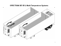
TK 53542-2-IM (Rev. 7, 06/12)
Trailer Edition
SPECTRUMTM DE SR-2
Multi-Temperature Systems
Installation Manual-A
Providing equipment and services to manage controlled-temperature environments for
food and other temperature-sensitive products, our Climate Control Technologies sector
encompasses both transport and stationary refrigeration solutions. Our product brands include
Thermo King®, a world leader in transport temperature control systems, and Hussmann®, a
manufacturer of refrigeration and food merchandising equipment.
www.thermoking.com
www.hussmann.com
www.ingersollrand.com
©2009 Ingersoll-Rand Company
Printed in U.S.A. on Recycled Paper
Installation Manual—A
Trailer Edition
SPECTRUM™ DE SR-2
Multi-Temperature Systems
TK 53542-2-IM (Rev. 7, 06/12)
Copyright© 2006 Thermo King Corp., Minneapolis, MN, U.S.A.
Release History
Released
08/06
Rev. 1
(01/07) Updated art to show correct 8 wire remote controller harness, multiple door switch harness with diodes
and CargoWatch sensor.
Rev. 2
(04/09) Updated the battery information page 20 and added new fuel tank bracket installation instructions pages
34-39.
Rev. 3
(01/10) Pages 62-63; Added new heavy duty battery hold down bracket.
Rev. 4
(04/11) Pages 12-13; added min/max dimensions for unit mounting bolts, page 14; updated unit dimension,
pages 20-23 and 56; added “Contact your Thermo King Dealer for specific part number”, page 20; added
Standard Display, Fuel Combo and Triple Combo Status Light Dimensions, page 21; add flush mounted Status
Light dimensions, pages 34-37; added 50 gallon Ultrasonic Fuel Level Sensor (USFLS) tank information, page
40; changed sensor harness wire code from 8F to 2PL and added “Thermo King recommends a conduit or
chase with 1.00 in (25.4 mm) I.D. to accommodate the electrical harness”., page 42-43; added details on how to
install and connect Status Lights, page 54-55; changed maximum gap from 19mm (0.75”) to 12.7mm (0.50”),
pages 58-59; removed reference to European Applications.
Rev. 5
(11/11) Page 7 - Revised Safety Precautions to include new Battery Installation and Cable Routing warnings and
cautions.
Rev. 6
(01/12) Page 34 -Added information about installing the optional Ultrasonic Fuel Level Sensor (UFLS) into the
fuel tank.
Rev. 7
(06/12) Page 56 - Added note about installing CargoLink wireless door switches.
2
SPECTRUM DE SR-2 Multi-Temperature Systems
3
Introduction
Installation Manual-A was written to assist with the installation of the Thermo King SPECTRUM DE SR-2 refrigeration systems onto trailers specifically
designed and built for refrigerated applications.
Due to its complexity, you should not attempt this installation unless you:
•
are an experienced mechanic.
•
can safely lift 34 kilos (75 lbs.)
•
are certified or trained in the repair and maintenance of
diesel powered refrigeration systems.
•
have a basic understanding of electricity and electrical wiring.
•
have the necessary tools and equipment to complete the installation.
Installation Manual-B was written to complete the installation of the
Multi-Temperature systems with Spectrum remote evaporators.
This manual is published for informational purposes only. Thermo King makes no representations warranties express or implied, with respect to
the information recommendations and descriptions contained herein. Information provided should not be regarded as all-inclusive or covering
all contingencies. If further information is required, Thermo King Corporation Service Department should be consulted.
Thermo King’s warranty shall not apply to any equipment which has been “so installed, maintained, repaired or altered as, in the manufacturer’s
judgment, to affect its integrity.”
Manufacturer shall have no liability to any person or entity for any personal injury, property damage or any other direct, indirect,
special, or consequential damages whatsoever, arising out of the use of this manual or any information, recommendations or
descriptions contained herein.
4
Table of Contents
Safety Precautions . . . . . . . . . . . . . . . . . . . . . . . . . . . . . . . . . . . . . . . . . . . . . . 6
Installing the Unit . . . . . . . . . . . . . . . . . . . . . . . . . . . . . . . . . . . . . . . . . . . . . . 30
Trailer Requirements . . . . . . . . . . . . . . . . . . . . . . . . . . . . . . . . . . . . . . . . . . . . . 8
Installing the Drain Hoses . . . . . . . . . . . . . . . . . . . . . . . . . . . . . . . . . . . . . . . 32
Evaporator Opening Requirements . . . . . . . . . . . . . . . . . . . . . . . . . . . . . . . . 10
Installing the UFLS (Option) . . . . . . . . . . . . . . . . . . . . . . . . . . . . . . . . . . . . . 34
Mounting Hardware Requirements . . . . . . . . . . . . . . . . . . . . . . . . . . . . . . . . 12
Installing the Fuel Tank - 50 Gallon, 22'' Diameter, Aluminum . . . . . . . . . . 36
Unit Dimensions . . . . . . . . . . . . . . . . . . . . . . . . . . . . . . . . . . . . . . . . . . . . . . . 14
Installing the Fuel Lines . . . . . . . . . . . . . . . . . . . . . . . . . . . . . . . . . . . . . . . . . 40
Battery Selection Guide . . . . . . . . . . . . . . . . . . . . . . . . . . . . . . . . . . . . . . . . . 16
Installing the UFLS Harness (Option) . . . . . . . . . . . . . . . . . . . . . . . . . . . . . . 42
Group 31 Battery Dimensions . . . . . . . . . . . . . . . . . . . . . . . . . . . . . . . . . . . . 17
Installing the Status Light (Option) . . . . . . . . . . . . . . . . . . . . . . . . . . . . . . . . 44
Lifting Bar Dimensions . . . . . . . . . . . . . . . . . . . . . . . . . . . . . . . . . . . . . . . . . . 18
DE Split-Evaporator Installation . . . . . . . . . . . . . . . . . . . . . . . . . . . . . . . . . . 46
Surface Mounted Status Light Dimensions (Option) . . . . . . . . . . . . . . . . . . 20
Installing the Rear Remote Controller (Option) . . . . . . . . . . . . . . . . . . . . . . 52
Flush Mounted Status Light Opening Dimensions (Option) . . . . . . . . . . . . 21
Installing the Door Switch (Option) . . . . . . . . . . . . . . . . . . . . . . . . . . . . . . . . 56
Rear Remote Controller Dimensions (Option) . . . . . . . . . . . . . . . . . . . . . . . 22
CargoWatch™ Sensor Locations (Option) . . . . . . . . . . . . . . . . . . . . . . . . . . 60
Door Switch Dimensions (Option) . . . . . . . . . . . . . . . . . . . . . . . . . . . . . . . . . 23
Connecting the CargoWatch™ Sensors (Option) . . . . . . . . . . . . . . . . . . . . 62
Required Tools . . . . . . . . . . . . . . . . . . . . . . . . . . . . . . . . . . . . . . . . . . . . . . . . 24
Installing the Battery . . . . . . . . . . . . . . . . . . . . . . . . . . . . . . . . . . . . . . . . . . . 64
Installation Components . . . . . . . . . . . . . . . . . . . . . . . . . . . . . . . . . . . . . . . . . 26
Installing the Bottom Pan . . . . . . . . . . . . . . . . . . . . . . . . . . . . . . . . . . . . . . . . 66
Unpacking the Unit . . . . . . . . . . . . . . . . . . . . . . . . . . . . . . . . . . . . . . . . . . . . . 28
5
Safety Precautions
The
symbol appears next to a point that is particularly important:
DANGER: Addresses a circumstance that, if encountered, will
lead to death or serious injury
WARNING: Addresses a circumstance that, if encountered,
might lead to death or serious injury.
CAUTION: Addresses a circumstance that, if encountered,
may cause damage to equipment or minor injury.
DANGER: Never operate the unit with the discharge valve
closed because it could cause the compressor to explode,
causing death or serious injury.
DANGER: Never apply heat to a sealed refrigeration system
or container because it could explode, causing death or
serious injury
DANGER: Fluorocarbon refrigerants, in the presence of an
open flame or electrical short, produce toxic gases that are
severe respiratory irritants capable of causing death.
DANGER: Be careful when working with a refrigerant or
refrigeration system in any enclosed or confined area with a
limited air supply (i.e., a trailer, container or the hold of a
ship). Refrigerant tends to displace air and can cause oxygen
depletion which may result in death by suffocation.
WARNING: Always wear goggles or safety glasses.
Refrigerant liquid, refrigeration oil, and battery acid can
permanently damage the eyes (see First Aid under
Refrigeration Oil).
WARNING: Keep your hands away from fans and belts when
the unit is running. This should also be considered when
opening and closing the compressor service valves.
WARNING: Make sure gauge manifold hoses are in good
condition. Never let them come in contact with a belt, fan
motor pulley, or any hot surface.
WARNING: Make sure all mounting bolts are tight and are of
correct length for their particular application
WARNING: Never drill holes in the unit unless absolutely
necessary. Holes drilled into the unit may weaken structural
components. Holes drilled into electrical wiring can cause fire
or explosion.
WARNING: When using ladders to install or service
refrigeration systems, always observe the ladder
manufacturer’s safety labels and warnings. A work platform is
the recommended method for installations.
WARNING: Exposed coil fins are very sharp and can cause
painful lacerations.
6
Safety Precautions (continued)
Battery Installation and Cable Routing
WARNING: Improperly installed battery could result in a fire or
explosion! A Thermo King approved battery must be installed
and properly secured to the battery tray.
WARNING: Improperly installed battery cables could result in
fire or explosion! Battery cables must be installed, routed and
secured properly to prevent them from rubbing, chaffing or
making contact with hot, sharp or rotating components.
Refrigerant
WARNING: Although fluorocarbon refrigerants are classified
as safe refrigerants, certain precautions must be observed
when handling them or servicing a unit in which they are
used. When released to the atmosphere in the liquid state,
fluorocarbon refrigerants evaporate rapidly, freezing anything
they contact.
First Aid
FROST BITE: In the event of frost bite, the objectives of First Aid are to
WARNING: Do not attach fuel lines or any additional wiring
harnesses to the battery cables as this could cause an
electrical fire!
CAUTION: Do not connect other manufacturer’s equipment or
accessories to the Thermo King unit. This could result in
severe damage to equipment and void the warranty!
CAUTION: Set all unit electrical controls to the OFF position
before connecting battery cables to the battery to prevent unit
from starting unexpectedly and causing personal injury.
CAUTION: Always wear protective clothing, gloves and eye
wear when handling and installing batteries. Battery acid can
cause serious burns when exposed to eyes or skin. If battery
acid contacts skin or clothing, wash immediately with soap
and water. If acid enters your eye, immediately flood it with
running cold water for at least twenty minutes and get medical
attention immediately.
protect the frozen area from further injury, to warm the affected area
rapidly and to maintain respiration.
EYES: For contact with liquid, immediately flush eyes with large amounts
of water and get prompt medical attention.
SKIN: Flush area with large amounts of lukewarm water. Do not apply
heat. Remove contaminated clothing and shoes. Wrap burns with dry,
sterile, bulky dressing to protect from infection/injury. Get medical
attention. Wash contaminated clothing before reuse.
INHALATION: Move victim to fresh air and use CPR or mouth-to-mouth
ventilation, if necessary. Stay with victim until arrival of emergency
medical personnel.
Refrigeration Oil
WARNING: Avoid refrigeration oil contact with the eyes. Avoid
prolonged or repeated contact of refrigeration oil with skin or
clothing. Wash thoroughly after handling refrigeration oil to
prevent irritation.
First Aid
CAUTION: Always cover battery terminals to prevent them
from making contact with metal components during battery
installation. Battery terminals grounding against metal could
cause the battery to explode.
NOTE: In case of eye contact, immediately flush with plenty of water
for at least 15 minutes. CALL A PHYSICIAN. Wash skin with soap and
water.
7
Trailer Requirements
DANGER: The front trailer must be structurally strong enough to support the weight of the refrigeration unit!
Approximate Weight
SPECTRUM DE (1670 lbs.) to 885 kg (1950 lbs.)
CAUTION: The minimum distance from the king pin to the front of the trailer must be 1025 mm (40.35 in.) or severe damage to the equipment will
result. VERIFY THIS DIMENSION BEFORE INSTALLING UNIT!
CAUTION: The minimum clearance required for the swing radius must be 1664.2 mm (65.520 in.) or severe damage to the equipment will result.
VERIFY THIS DIMENSION BEFORE INSTALLING UNIT!
8
Trailer Requirements
9
Evaporator Opening Requirements
Evaporator Opening
DANGER: The front trailer wall must be structurally strong
enough to support the weight of the refrigeration unit!
The location of the unit mounting bolts and evaporator opening in the front
wall is critical.
VERIFY ALL DIMENSIONS BEFORE INSTALLING UNIT!
NOTE: It may be necessary to relocate the front corner clearance
lights to the corner radius of the trailer to prevent damage.
1. The evaporator opening must be square. The diagonal measurements
must be ±3.0 mm (0.12 in.)
2. The gasket surface around the opening must be at least 76.2 mm
(3.00 in.) wide, be flat ±3.2 mm (0.05 in.) and free of rivets, seams or
bolt heads.
10
Evaporator Opening Requirements
11
Mounting Hardware Requirements
Mounting Bolts
DANGER: Eight mounting bolts must be installed to properly
secure the unit to the trailer front wall! Failure to do so could
result in severe damage to equipment, void the warranty or
cause personal injury or death!
NOTE: The location of the unit mounting bolts in the trailer front wall
is critical to proper unit installation.
Mounting Bolt Specifications
DANGER: The use of mounting bolts other than those
specified could result in severe damage to equipment, void
the warranty or cause personal injury or death!
Use Metric M12 x 1.75 pitch class 8.8 (1/2 in.-13 UNC - 28 Rolled thread
grade 5), medium carbon steel bolts and locking nuts. All hardware must
be zinc plated with dichromate finish.
All mounting bolts must be square with the front wall and securely
fastened to the trailer wall in such a manner to allow the mounting nuts be
torqued to 82 N•m (60 ft. lbs.) from outside the trailer.
•
Mounting bolts are to extend a minimum 57.20 mm (2.25 in.) and a
maximum of 63.50 mm (2.50 in.) beyond the front wall.
•
Surface of all mounting bolts are to be flat within 2.50 mm
(0.10 in.).
12
Mounting Hardware Requirements
13
Unit Dimensions
14
BLANK PAGE
15
Battery Selection Guide
Refer to Service Bulletin T&T 446 for more information regarding Battery Selection and Maintenance.
CAUTION: Do not connect other manufacturer’s equipment or
accessories to the Thermo King unit! This could result in
severe damage to equipment and void the warranty!
IMPORTANT: The specified battery, electrical wiring and electronic
controls were designed to operate and maintain only the Thermo
King refrigeration system and factory authorized Thermo King
options.
Trailer units are designed for one 12 volt, Group 31 battery supplied by the
installer.
The battery must be suitable for deep cycling, heavy duty and rated with a
minimum of 95 amp/hr.
NOTE: See following table for Thermo King approved batteries.
Refer to Service Bulletin T&T 446 for more information regarding
Battery Selection and Maintenance.
BATTERY APPLICATION TABLE
750 CCA Wet Cell
Thermo King ReliaMax 750S
P/N 203-731 Threaded Stud
P/N 203-730 SAE Post
925 CCA Wet Cell
Thermo King ReliaMax 925N
P/N 203-733 Threaded Stud
P/N 203-732 SAE Post
1150 CCA Dry Cell (AGM)
Thermo King EON
P/N 203-550 Threaded Stud
P/N 203-551 SAE Post
• Wet Cell Technology
• Better suited for warmer climates
• Less cranking power at low
ambient temperatures
• 18-24 month expected life *see
note below
• Choose for southern climates
• Wet Cell Technology
• Better suited for colder climates
• High cranking power at low
ambient temperatures
• 18-24 month expected life *see
note below
• Choose for northern climates
• Dry Cell (AGM) Technology
• Better suited for all applications
• High cranking power at lower
ambient temperatures
• Suited for extreme temperatures
• Best for high cycling applications
(Cycle-Sentry use)
• 5-7 year expected life
* NOTE: Wet cell battery life and maintenance requirements are determined by the operating environment and the
charge/discharge rate (cycles) while the battery is in service. Higher ambient temperatures and frequent discharges
will shorten a wet cell battery’s overall life expectancy and increase maintenance requirements.
16
Group 31 Battery Dimensions
17
Lifting Bar Dimensions
WARNING: Do not use a fork lift to install unit! This could
result in severe damage to the equipment, void the warranty or
cause personal injury or death!
WARNING: Thermo King requires a 3 point lifting bar to safely
lift and install units. A lifting bar can be made from the
drawings provided.
WARNING: All hardware used to assemble the lifting bar must
be DIN 931 class 10.9 (SAE grade 8). The use of hardware
other than specified may cause personal injury, severe
damage to the evaporator and void the warranty.
WARNING: The lifting bar and lifting device combined must be
able to support minimum weight of 1360.8 kilos (1 1/2 tons).
I. Recommended material: 76.2 mm (3.00 in.) x 12.7 mm (0.50 in.) mild
steel.
II. Use forged chain links and hooks, clevis and pins with strength equal to
total lift capacity of hoist mechanism and meet all safety standards.
III. Bolt together for maximum strength and safety.
1. Forged Clevis Pin.
2. Forged Chain Links.
3. Locking Master Chain Link.
18
Lifting Bar Dimensions
19
Surface Mounted Status Light Dimensions (Option)
Contact your Thermo King Dealer for specific part numbers.
Standard Display and Fuel Combo Display
Triple Combo Display
20
Flush Mounted Status Light Opening Dimensions (Option)
Contact your Thermo King Dealer for specific part numbers.
NOTE: Dimensions shown will accommodate the flush mounted Standard Display, Standard and Fuel Combo Display and Triple Combo Display.
21
Rear Remote Controller Dimensions (Option)
Contact your Thermo King Dealer for specific part numbers.
22
Door Switch Dimensions (Option)
Contact your authorized Thermo King Dealer for specific part numbers.
23
Required Tools
1. Safety Glasses
2. Drill
3. Drill Bits
4. Tape Measure
5. Mechanics Tools
6. Lifting Bar
7. Work Platform (Recommended)
8. Torque Wrench
9. Forged Eyebolts
NOTE: Equipment such as scales, gauges, refrigerant leak detectors,
and torque wrenches should be in good working condition and
routinely calibrated to assure accurate readings.
24
Required Tools
25
Installation Components
1. Locking Nuts
2. Washers
3. Self Tapping Screws
4. Clamps
5. Cable Ties
6. Fuel Line Hose
1/4 in.
3/8 in.
7. Fuel Line Fittings
1/4 in.
3/8 in.
8. Fuel Line Connector
9. Drain Hose Check Valve
26
Installation Components
27
Unpacking the Unit
DANGER: Do not use a forklift to install the unit! This could
result in severe damage to the equipment, void the warranty
or cause personal injury or death!
WARNING: Thermo King requires a 3 point lifting bar to safely
lift and install units. A lifting bar can be made from the
drawings provided (see Lifting Bar Dimensions).
Units are shipped attached to disposable wooden pallet wrapped with
protective cardboard and plastic stretch wrap.
NOTE: To avoid unnecessary damage to your unit, place the crated
unit near the trailer prior to its removal.
Unpacking the Unit
•
Carefully remove plastic stretch wrap from unit.
•
Carefully remove the top cardboard cover.
•
Carefully remove the outer cardboard wrap.
•
Remove installation kit boxes, bottom panel, and any other loose
components from rear of unit.
•
Attach forged eyebolts and 3 point lifting bar to unit.
•
Remove hardware holding unit to wooden pallet.
•
Unit is now ready for installation.
IMPORTANT: DO NOT use a sharp knife to remove the stretch wrap or
cardboard wrap as damage to the exterior of the unit will result!
28
Unpacking the Unit
29
Installing the Unit
WARNING: Do not use a forklift to install the unit! This could
result in severe damage to equipment, void the warranty or
cause personal injury or death!
WARNING: Use only locking hooks to safely lift the unit!
Failure to use locking hooks could result in severe damage to
the equipment, void the warranty or cause personal injury or
death! (Detail I).
WARNING: Thermo King requires a 3 point lifting bar to safely
lift and install units. A lifting bar can be made from the
drawings provided. See “Lifting Bar Dimensions” on page 18.
Unit Installation
9. Install two 5/8-11 forged lifting eyebolts into threaded holes located on
the top of the unit (Detail I).
10. Use the lifting bar to lift unit up to the trailer opening.
NOTE: All nuts that hold the unit to the trailer should be elastic stop
nuts (Nylock Type) provided in the installation kit.
11. Attach washer and elastic stop nuts provided in the installation kit.
Torque to 82 N•m (60 ft. lbs.).
Access to Mounting Holes (Detail II)
1. Top side mounting hole through the hinged roadside grille.
2. Center side mounting hole through hinged roadside grille.
3. Lower side mounting hole through hinged roadside panel, and control
box hole.
4. Center side mounting hole through hinged lower curbside door.
5. Lower side mounting hole through hinged curbside panel.
6. Center side mounting hole through hinged curbside grille.
7. Top side mounting hole through hinged curbside grille.
8. Top center mounting hole from top of the unit.
30
Installing the Unit
31
Installing the Drain Hoses
Installing the Drain Hoses
1. Drain Hoses should run straight down the trailer wall from the unit with
no kinks or bends.
2. Secure with screws and clamps provided in installation kit.
3. Cut off excess hose and attach drain hose check valves provided in
installation kit.
32
Installing the Drain Hoses
33
Installing the UFLS (Option)
Important Installation Information
The Ultrasonic Fuel Level Sensor (UFLS) should be installed into the fuel
tank before the tank is installed onto the trailer.
If the fuel tank has already been installed, disconnect negative battery cable
from unit, disconnect and cap all fuel lines, drain fuel from tank and
remove tank from trailer.
• DO NOT connect power to the UFLS until it has been installed into
the fuel tank.
• DO NOT use thread locking compounds as they can cause stress
cracking of the plastic sensor.
• DO NOT apply any type of gasket sealer.
• USE ONLY the new gaskets supplied with the UFLS.
• DO NOT use power tools to tighten the mounting hardware or
damage to the plastic sensor will result.
• DO NOT overtighten the mounting hardware or damage to the
plastic sensor will result.
1. Remove and discard the access cover, gasket and hardware from the
fuel tank. DO NOT reuse any of these parts.
•
Confirm the gasket surface area on the tank flange is clean.
Pre-Assembly
NOTE: The mounting holes of the sensor, focus tube, gaskets and
the fuel tank flange are not symmetrical. The holes align only in one
position. The distance between the two mounting holes next to the
notch (see illustration) are further away than the others. These two
holes will be used as a reference point to correctly align the
components.
2. The UFLS assembly should be pre-assembled before installing it into
the fuel tank.
• Slide a gasket up the focus tube to the flange making sure the pin
hole in the gasket is centered between the two mounting holes next
to the notch as shown.
• While holding the lower gasket in place, place the upper gasket
onto the focus tube flange, again making sure the pin hole in the
gasket is positioned between the two mounting holes next to the
notch as shown.
• Place the sensor on top of the upper gasket with the harness
pointing towards the notch on the focus tube flange. All holes
should now be aligned.
• Install the 10-32 screws, lock washers and flat washers onto the
sensor and through the gasket holes to hold the assembly together.
Installation in Tank
3. Insert assembly into fuel tank making sure the notch on the focus tube
is aligned with the notch on the tank flange. When installed correctly,
the sensor harness will be pointed towards the fuel fill on the end of the
tank.
• Hand tighten the five mounting screws in a criss-cross pattern
and torque them to 10-15 in-lbs (1.1-1.7 N•m).
• DO NOT overtighten the mounting hardware or damage to the
plastic sensor will result.
• The fuel tank is now ready to be installed.
34
Installing the UFLS (Option)
35
Installing the Fuel Tank - 50 Gallon, 22'' Diameter, Aluminum
OPEN STYLE TANK MOUNTING BRACKET
IMPORTANT FUEL TANK INSTALLATION INFORMATION
Effective the first quarter of 2011, all 50 gallon, 22'' diameter, aluminum
fuel tanks will come equipped with the mounting flange for the Ultrasonic
Fuel Level Sensor (USFLS) option.
•
A.
DANGER: An improperly installed fuel tank could lead to
serious injury or death! Consult your trailer manufacturer for
specific details on proper fuel tank installation and
recommendations.
B.
CAUTION: The trailers crossmembers must be strong enough
to safely support the combined weight of the mounting
hardware, fuel tank and fuel.
Fuel Tank Capacity
Combined Total Weight
50 Gallon Diesel
214 KG (471 lbs.)
Open Style Tank Mounting Bracket - New fuel tank mounting kits were
released November 1, 2008. Factory Kit 701635 and Aftermarket Kit
90-398 contain a new open style fuel tank mounting bracket. This new
mounting bracket can be used to install either a 30 or 50 gallon, 22''
diameter fuel tanks onto a typical trailer with standard crossmember
spacing of 6'', 8'', 10'' or 12''.
• Trailers with non-standard crossmember spacing of 9'', 15'' and 16'' will
require the additional components found in Kit 701658 (90-399) to
complete the installation.
• These new kits can not be used to install a 75, 90, 110 or 120 gallon,
22'' diameter fuel tanks. Those tanks require Kit 710278 (90-121).
• DO NOT substitute any components from Kits 701635 (90-398) and
701658 (90-399) with any previously supplied fuel tank mounting kits
as they are not interchangeable.
C.
D.
Kits 701635 (90-398) and 701658 (90-399) are specifically designed to
install a 30 or 50 gallon fuel tank in a hanging position under a trailer
attached to the floor crossmembers. Substitutions are not acceptable!
Fuel Tank Position
• Thermo King recommends the fuel tank be mounted 203.2 mm
(8.00 in.) under the trailer as shown. Otherwise, the OEM or
installer is responsible to ensure the fuel tank position meets or
exceeds DOT or Federal Highway regulations, when applicable.
Tank Strap Position
• 50 Gallon Tanks - Fuel tank straps must be positioned 673 mm
(26.50 in.) apart as shown.
Rubber Strips and Pads
• Rubber strips must be properly installed on both the mounting
bands and the rubber pads must be installed onto the underside of
the hanger assemblies to prevent metal to aluminum contact.
Mounting Hardware
• Grade 5 mounting hardware is supplied. Substitutions are not
acceptable!
• All mounting hardware must be properly installed and torqued to
the specifications listed.
Hardware Size
Torque Specifications
3/8-16 Grade 5
42 N•m (31 ft-lb)
1/2 -13 Grade 5
81 to 88 N•m (60-65 ft-lb)
1/2'' T-bolts
48 N•m (35 ft-lb.)
36
Installing the Fuel Tank - 50 Gallon, 22'' Diameter, Aluminum
OPEN STYLE TANK MOUNTING BRACKET
Standard crossmember spacing shown. For other crossmember spacing, refer to TK-54238-2-IM.
Non-standard crossmember spacing of 9'', 15'' and 16'' also requires Kit 701658 (90-399)
NOTE: Location of mounting holes may change if other
trailer options are added.
Flange
Tank can be mounted on
either side of trailer.
37
Installing the Fuel Tank - 50 Gallon, 22'' Diameter, Aluminum
OPEN STYLE TANK MOUNTING BRACKET
Fuel Tank Installation
NOTE: Location of mounting holes may change if other trailer
options are added.
1. Locate the existing sets of 10.3 mm (.406'' dia.) pre-punched holes in
the crossmembers. See note above.
2. Align the two holes of each hanger bracket with the holes in the
crossmember and secure with two, 3/8-16 screws, washers and locking
nuts. Torque the hardware to 42 N•m (31 ft-lb).
3. Install each hanger assembly (facing each other as shown) onto the
hanger brackets with 1/2-13 screws, washers and locking nuts. Torque
the hardware to 81 to 88 N•m (60-65 ft-lb).
4. Install a self-adhesive rubber pad to the underside of each hanger
assembly.
5. Loosely install the tank straps t-bolts onto the hanger assemblies with
1/2'' washers and locking nuts. Verify the rubber strips are properly
installed on the mounting bands.
6. Install the fuel tank into the straps with the tank positioned vertically
within plus or minus 5 degrees and tighten the tank straps to
48 N•m (35 ft-lb).
38
Installing the Fuel Tank - 50 Gallon, 22'' Diameter, Aluminum
OPEN STYLE TANK MOUNTING BRACKET
NOTE: Location of mounting holes may
change if other trailer options are added.
Open Style Bracket
Orient Tank
Vertically
Flange
39
Installing the Fuel Lines
Fuel Line Installation
DANGER: Leaking fuel lines could cause a fire resulting in
death or serious injury! All fuel line fittings must be tight and
leak free!
DANGER: Do not route fuel lines with battery cables or
electrical wires, as this could cause a fire!
1. Install the fuel line bracket to the pre-drilled hole in the frame. This
hole is located in the frame under the compressor (Detail I).
IMPORTANT: Verify the factory installed fuel line fittings are tight
prior to mounting the bracket onto the frame.
2. Fuel lines should be routed in a protective housing with no kinks or
sharp bends (Detail II).
4. Secure all fuel lines with provided clamps (Detail III).
5. Route fuel supply line from the unit to the fuel pump to the fuel pickup
on the fuel tank. Install fuel line connector (provided in installation kit),
cut end of fuel line at a 45 degree angle and insert into fuel pickup tube
until it is 25.4 mm (1.00 in.) from bottom of tank and tighten securely
(Detail IV).
6. Route fuel return line from the unit to the fuel tank return fitting.
Attach fuel line connectors and tighten securely.
7. Remove plastic cap from the fuel vent and point the outlet to the rear of
the trailer.
NOTE: Add a sufficient amount of fuel (1/4 tank) to allow the unit to
run for 8 to 12 hours during engine break-in and pre-delivery
procedures.
3. Rubber grommets must be used when routing fuel lines through holes
in metal (Detail II).
40
Installing the Fuel Lines
Verify the factory installed
fuel line fittings are tight
prior to mounting the bracket
onto the frame.
41
Installing the UFLS Harness (Option)
“Solid State” Ultrasonic Fuel Level Sensor (UFLS)
Harness Installation and Routing
Harness Connections
NOTE: The Ultrasonic Fuel Level Sensor (UFLS) is an option for 22”
50 gallon fuel tanks only and requires Interconnect Harness Kit
702414.
IMPORTANT: The use of the supplied crimp and solder style
connectors with separate heat shrink tubing is required when
connecting the sensor harness to the UFLS.
DANGER: Do not route electrical wires with fuel lines as this
could cause a fire!
1. Locate the short factory installed fuel level sensor harness with the
3-pin connector. This connector is located outside the control box and
band wrapped to other harnesses at the rear of the unit near the frame
mounted ground plate.
3. Cut the interconnect harness to length and splice wires to the fuel
sensor’s leads:
J3 Connector at
Controller
2PL
PIN A
GREEN
RED
PIN 35
FUELN
PIN B
BLACK
BLACK
FLL
PIN C
WHITE
YELLOW
Apply a light coating of Superlube or equivalent to this connector.
PIN 23
•
Connect the 30 ft. (9.1 m) Interconnect Harness to the mating
3-pin connector on the factory installed harness.
•
NOTE: Thermo King recommends a conduit or chase with 1.00 in
(25.4 mm) I.D. to accommodate the electrical harness.
Fuel Sensor Leads
PIN 12
•
2. Route the harness to the fuel tank using trailer’s harness conduit or
chase to avoid interference with fifth wheel plate area.
Interconnect Harness
Outside Control Box
•
•
•
Slide supplied heat shrink tubing onto each wire and position them
away from joint.
Connect each wire with wire connector and crimp securely.
Solder wires to wire connectors with a soldering gun.
Slide heat shrink tubing over each wire connector and applying heat
with a heat gun.
IMPORTANT: DO NOT burn the heat shrink. If the heat shrink is burnt,
charred, or has bubbles from overheating, the wire connections must
be removed and redone correctly.
4. Use supplied cable ties, clamps and screws to secure the harness.
IMPORTANT: This is a “Solid State” fuel level sensor and the SR-2
Controller must be programmed accordingly to enable the fuel level
feature.
42
Installing the UFLS Harness (Option)
Ultrasonic Fuel Level Sensor (UFLS)
Crimp and Solder Style Connectors
Heat Shrink Tubing
Interconnect Harness
43
Installing the Status Light (Option)
Installation
NOTE: Surface mounted status light installation shown, flush
mounted light installs into recessed opening (see “Flush Mounted
Status Light Opening Dimensions (Option)” on page 21) and
electrical connections are made the same.
1. Mount the Status Light in a location so that is visible in the tractor
mirror to the driver.
•
Mark and drill the four mounting holes using a 3/16'' drill.
•
Mount the status light in position with the supplied rivets.
NOTE: If all CAN ports are occupied use the CAN extender Harness
available from your Thermo King Dealer.
•
Be sure the connectors are locked securely in place on the circuit
board.
•
Secure any excess harness with tie bands to the main harness
behind the battery tray.
IMPORTANT: DO NOT secure excess harness to battery cables or
refrigeration lines.
2. Route harness as shown allowing a “drip-loop” to prevent water from
migrating into the Status Light.
3. Secure harness to the bracket and trailer using the supplied clamps and
rivets.
4. Connecting the Status Light harness:
STANDARD DISPLAY - connect harness to the matching 6-pin
connector located outside the unit behind the battery tray and to the left
of the control box.
•
Secure any excess harness with tie bands to the main harness
behind the battery tray.
FUEL COMBO and TRIPLE COMBO DISPLAYS - route the
harness through the harness grommet and into the control box.
•
Connect the 4-pin connector to the Remote Light port on the circuit
board.
•
Connect the 8-pin connector to CAN1 (J12). If this position is
occupied use CAN2 (J13) or CAN3 (J14).
44
Installing the Status Light (Option)
8-Pin
4-Pin
45
DE Split-Evaporator Installation
CAUTION: Do not drill holes into refrigeration, electrical or
mechanical components or severe damage to the equipment will
result!
Return Airflow
Restrictions of the return airflow adversely affects the performance of the
unit. The area directly behind the evaporator return air inlet must not be
restricted.
Bulkhead Function
A bulkhead is used to keep the return airflow from being restricted if the
load shifts. The bulkhead also prevents the load from shifting into the
return airflow passageway on the front wall of the trailer.
DE Split-Evaporator Installations
All center-partition (longitudinally split trailer) installations are unique due
to the splitting of the air supply outlets and air supply returns.
Bulkhead (Detail I)
1. A special bulkhead must be installed that allows the return air to be
routed back to each roadside and curbside evaporator.
2. From the center line (C/L) of the unit measure 11.5 in. (292 mm) to
locate the unit’s internal center divider.
3. The bulkhead must have a divider channel that runs from the unit’s
internal center divider down to the trailer floor. This diagonal partition
divider must be insulated with the 2.00 in. (50.8 mm) thick foam
insulation supplied in the installation kit.
4. Insulate the entire triangular area, inside the bulkhead, where the air
return crosses over into the opposite compartment with the 1.00 in.
(25.5 mm) thick foam insulation supplied in the installation kit.
5. All air gaps between the top edge of the bulkhead and the evaporator
panel must be sealed completely with foam insulation or caulking.
6. The bulkhead must be equipped with a lower air inlet screen to prevent
debris from entering into the air inlet openings.
The following details are critical to this installation:
Center Wall Partition (Detail II)
•
A special bulkhead must be installed and sealed properly to “split” the
air supply returns for each compartment.
7. A small section of the center partition must be modified to route the air
supply from the roadside evaporator to the roadside compartment.
•
The center wall partition must be modified and sealed properly to
“split” the air supply outlets for each compartment.
•
Air gaps must be properly sealed with foam insulation or caulking.
46
DE Split-Evaporator Installation
I
II
47
DE Split-Evaporator Installation
Sealing Air Gaps
NOTE: The following areas must be properly sealed to prevent air
leakage and allow the unit to operate correctly.
1. Area Above the DE Evaporator Section - If the remote tubing is routed
across the trailer to the curbside compartment, this area requires foam
block be cut to fit around the insulated tubing and harness.
2. Gap Between Top of Evaporator and Trailer Header - This gap (below
trailer header and above the evaporator) should be filled with foam
insulation or caulking.
3. Front Edge of Center Partition - Although the front edge of the center
wall partition may have a conforming gasket it cannot conform to
severe steps anywhere along the bulkhead or above the evaporator. The
long foam adhesive backed strip (1.00 in. x 4.00 in.) supplied in the DE
installation kit may be used here, if necessary.
5. Front Wall and Center Divider Interface - Special care must be taken
because the insides of the trailer walls are not necessarily flat. If the
slanted center divider in the bulkhead is not flexible, foam tape and/or
caulking must be added to conform to the front wall.
6. Trailer Trough Area - The center divider in the bulkhead must extend
to the bottom of the floor/trough, even though the bulkhead itself must
end 6 to 10 in. (152.5 to 254 mm) above the trailer floor. This lower
extension of the divider should be flush with the bulkhead surface to
make it easy to seal the front edge of the center partition.
I = Standard Bulkhead
II = Foam Blocks (installer supplied)
III = Full Height Bulkhead
4. Top of Slanted Center Divider in Bulkhead - This area needs gaskets
to conform and seal against the bottom of the internal center divider
between the two DE evaporator. This prevents air leakage between the
two return air areas. Because the evaporators are offset towards the
trailer curbside, this center divider is located 11.5 in. (292 mm) to the
curbside of the trailer center line.
48
DE Split-Evaporator Installation
I
II
III
49
DE Split-Evaporator Installation
Typical DE Split-evaporator Installation
Only one of many possible configurations is shown for the Spectrum DE
application.
6. The entire triangular are, inside the bulkhead, where the air crosses
over to the opposite compartment must be insulated with at least
1.00 in. (25.4 mm) thick foam insulation.
NOTE: The Spectrum DE 30-2 does not have the capability for a remote
evaporator.
7. The transition section of the center portion must be provided to
accommodate the roadside and curbside air flow outlets. This must be
insulated similar to the center wall section.
1. Center Divider Partition must seal tight against the floor and ceiling of
the trailer.
8. If refrigeration tubes are routed for an optional remote evaporator, the
liquid and suction lines must be clamped together for heat exchange.
2. At least one rear bulkhead must always be installed with a frozen
compartment.
9. Remote evaporator (OPTIONAL).
3. Adjustable Bulkhead (OPTIONAL).
4. The trailer must be split into two separate compartments for proper
return air flow.
10. Minimum distance.
11. Maximum distance.
5. A special diagonal divider channel must be added within the return air
bulkhead to separate the roadside and curbside return air flow. This
diagonal partition must be insulated with foam at least 2.00 in.
(50.8 mm) thick and cover the bulkhead’s entire partition.
50
DE Split-Evaporator Installation
7
1
8
11
6
(7 288
31 .0
5
m in.
m)
5
4
9
(6 24.0
09 0
mm in.
)
10
4
1
3
AFD59
2
51
Installing the Rear Remote Controller (Option)
Foamed-In-Place Installation
NOTE: Verify mounting location and all dimensions before installing
the remote controller.
A = 69.8 mm (2.75 in.)
B = 196.8 mm (7.75 in.)
DANGER: Do not route electrical harness together with fuel
lines as this could cause a fire resulting in death or serious
injury!
CAUTION: Do not drill holes into refrigeration, electrical or
mechanical components or severe damage to the equipment
will result!
Harness Connections
7. Apply Superlube (or equivalent) to Remote Controller Harness
connector and attach securely to back of controller. Route harness
through chase. Secure controller to controller box with screws.
8. Route chase and Remote Controller Harness from controller to host
unit. Secure with clamps.
9. Cut off excess harness and strip wire ends.
•
Attach the Remote Controller Harness wires to the splice
connectors on the Interface Harness.
.
Remote Controller
Harness
(with flat 8-PIN connector)
Code
Interface Harness
(with 8-PIN connector
and splice ends)
Code
PIN 1
BLU
PIN 3
BLU
PIN 2
GRN
PIN 5
GRN
PIN 3
No
Connection
PIN 7
No
Connection
PIN 4
ORN
PIN 6
ORN
PIN 5
YEL
PIN 4
YEL
NOTE: The alternative routing of the electrical harness chase and
interface harness is from the side of the controller box.
PIN 6
BRN
PIN 8
BRN
PIN 7
BLK
PIN 1
BLK
3. Drill an appropriate size hole in the controller box for the harness chase
coupling.
PIN 8
RED
PIN 2
RED
Preferred Wire Routing (Steps 1,2, 6-10)
NOTE: The preferred routing of the electrical harness chase and
interface harness is from the bottom of the controller box.
1. Connect the harness chase to the bottom of controller while providing a
drip loop.
2. Install and route a 1/2 in. CPVC drain hose from the bottom of the
controller box out of trailer floor.
Alternative Wire Routing (Steps 3-10)
4. Install harness chase coupling.
NOTE: Coupling should not protrude more than 6.4 mm (0.25 in.)
inside the controller box.
10. Apply Superlube (or equivalent) and securely connect the Interface
Harness 8-PIN connector to the mating 8-PIN Remote Controller
connector located on the side of the evaporator housing.
5. Install cap in bottom of controller box before foaming trailer wall.
6. Apply chalking to controller box and install securely into trailer wall.
52
Installing the Rear Remote Controller (Option)
53
Installing the Rear Remote Controller (Option)
Retro-Fit Installation
NOTE: Verify mounting location and all dimensions before installing
the
DANGER: Do not route electrical harness together with fuel
lines as this could cause a fire resulting in death or serious
injury!
CAUTION: Do not drill holes into refrigeration, electrical or
mechanical components or severe damage to the equipment
will result!
CAUTION: Rubber grommets must be used when routing
electrical harnesses through metal holes!
1. Cut opening in trailer wall per dimensions shown.
A = 203 mm (8.0 in.)
B = 107.9 mm (4.25 in.)
C = 38 x 12.7 mm (1.5 x .5 in.)
2. Install and route a 1/2 in. CPVC drain hose and 0.88 O.D. harness
chase from the bottom of the controller box out of the trailer.
3. Apply caulking to controller box and install securely in trailer wall.
NOTE: Make sure the drain hose and harness chase are connected
properly.
Harness Connections
4. Apply Superlube (or equivalent) to Remote Controller Harness
connector and attach securely to back of controller. Route harness
through chase. Secure controller to controller box with screws.
5. Route harness under trailer through chase in floor or I-beam
crossmembers towards the unit.
6. From inside the trailer, measure and drill an appropriate size hole and
route the harness up into the trailer towards the unit.
7. Secure harness to the backside of the unit with clamps.
8. Measure the length of harness required for the harness to connect to the
8-Pin Remote Controller connector that is factory installed on the side
of the evaporator housing. Cut off excess harness and strip wire ends.
Crimp into existing splice and use heat shrink covering.
.
Remote Controller
Harness
(with flat 8-PIN connector)
Code
Interface Harness
(with 8-PIN connector
and splice ends)
Code
PIN 1
BLU
PIN 3
BLU
PIN 2
GRN
PIN 5
GRN
PIN 3
No
Connection
PIN 7
No
Connection
PIN 4
ORN
PIN 6
ORN
PIN 5
YEL
PIN 4
YEL
PIN 6
BRN
PIN 8
BRN
PIN 7
BLK
PIN 1
BLK
PIN 8
RED
PIN 2
RED
9. Apply Superlube (or equivalent) and securely connect the Interface
Harness 8-PIN connector to the mating 8-PIN Remote Controller
connector factory installed on the unit.
54
Installing the Rear Remote Controller (Option)
55
Installing the Door Switch (Option)
When installing CargoLink wireless door switches, see TK 55151 CargoLink Installation Manual.
NOTE: These instructions (pages 56-59) are intended as reference
guide only to assist with a typical hard wired door switch installation.
Your installation may be different depending on the trailer, the
amount and types of doors and the customers particular
requirements.
Door Switch Components
The door switch consists of a magnet, a switch, non-magnetic mounting
hardware and a interface harness to connect to the host unit.
• The magnet is always mounted on the door.
• The switch (with harness) is always mounted to a stationary location.
• Two short interface harnesses are available depending on your
particular kit. One allows a single door switch in a single zone to
activate a unit shutdown. The other allows two door switches in the
same zone to each activate a unit shutdown.
Non-magnetic mounting hardware is included to install the switches. If
alternate hardware is used it must also be non-magnetic or the door switch
will not operate properly.
Installer is to supply and fabricate the harness connecting the interface
harness to the door switch per the table below. The harness should be 18
AWG or better, 3 wires, color coded RED, BLACK and WHITE.
Interface Harness Wiring
RED = (12 Vdc) POWER
Door Switch Wiring
RED = (12 Vdc) POWER
BLACK = (CH) GROUND
BLACK = (CH) GROUND
WHITE = (DS) OUTPUT
WHITE = (DS) OUTPUT
Mounting Locations
The door switch can be mounted on the inside or outside of either swing
out or roll-up doors and can be mounted in various positions to
accommodate particular applications.
IMPORTANT INSTALLATION NOTES:
• The door switch must be installed away from traffic (i.e. forklifts) or
protected from it.
• The door switch and magnet must be installed parallel to each other,
not perpendicular. Long cross hair aligns to long cross hair.
• It is important that a maximum gap of 12.7 mm (0.50 in.) is maintained
between the door switch and the magnet. Shims may be required and
must be a non-magnetic material (aluminum, wood, plastic, etc.) or the
door switch will not operate properly.
(Detail A) Ceiling Mounted
1. Mount the magnet flush with the top edge of the door and secure with
supplied hardware.
2. Close the door and mount the switch to the door sill parallel with the
magnet, being sure the “cross hairs” are aligned and that the maximum
gap of 12.7 mm (0.50 in.) is maintained.
(Detail B) Floor Mounted
1. Mount the magnet flush with the bottom edge of the door and secure
with supplied hardware.
2. Close the door and mount the switch to the floor parallel with the
magnet, being sure the “cross hairs” are aligned and that the maximum
gap of 12.7 mm (0.50 in.) is maintained.
(Detail C) Outside Door Installation
1. Mount the magnet flush with the top edge of the door and secure with
supplied hardware.
2. Close the door and mount the switch to the door sill parallel with the
magnet, being sure the “cross hairs” are aligned and that the maximum
gap of 12.7 mm (0.50 in.) is maintained.
56
Installing the Door Switch (Option)
Right Angle Mounting
Top x Top Mounting
Side x Side Mounting
57
Installing the Door Switch (Option)
Contact your Thermo King Dealer for specific part numbers.
NOTE: The Door Switch Harness Connectors are located at the rear of the unit (See DETAIL C).
Single Door Switch Activation / Single Zone (Detail A)
Multiple Door Switch Activation / Single Zone (Detail B)
1. Attach the interface harness to the door switch connector located at the
rear of the unit.
4. Attach the interface harness to the door switch connector at the rear of
the unit.
2. Route a 3 wire harness (Installer Supplied) from the interface harness
to a single door switch. Connect matching wires per the table below
(RED/RED, WHITE/WHITE, BLACK/BLACK) to each door
switch using splice connectors. Crimp splice connectors securely and
apply heat with a heat gun.
5. Route a 3 wire harness (Installer Supplied) from the interface harness
to each door switch - Maximum Two Doors. Connect matching wires
per the table below (RED/RED, WHITE/WHITE, BLACK/
BLACK) to each door switch using splice connectors. Crimp splice
connectors securely and apply heat with a heat gun.
Interface Harness Wiring
RED = (12 Vdc) POWER
Door Switch Wiring
RED = (12 Vdc) POWER
Interface Harness Wiring
RED = (12 Vdc) POWER
Door Switch Wiring
RED = (12 Vdc) POWER
BLACK = (CH) GROUND
BLACK = (CH) GROUND
BLACK = (CH) GROUND
BLACK = (CH) GROUND
WHITE = (DS) OUTPUT
WHITE = (DS) OUTPUT
WHITE = (DS) OUTPUT
WHITE = (DS) OUTPUT
3. All harnesses should be installed, routed and properly secured to
protect from damage.
6. All harnesses should be installed, routed and properly secured to
protect from damage.
7. Operate unit and verify door switch operation.
58
Installing the Door Switch (Option)
Interface Harness Wiring
RED = (12 Vdc) POWER
Door Switch Wiring
RED = (12 Vdc) POWER
BLACK = (CH) GROUND
BLACK = (CH) GROUND
WHITE = (DS) OUTPUT
WHITE = (DS) OUTPUT
Door Switch
Connectors
Interface Harness Wiring
RED = (12 Vdc) POWER
Door Switch Wiring
RED = (12 Vdc) POWER
BLACK = (CH) GROUND
BLACK = (CH) GROUND
WHITE = (DS) OUTPUT
WHITE = (DS) OUTPUT
59
CargoWatch™ Sensor Locations (Option)
Sensor locations for Domestic Applications as required by customer.
1. Sensor #1 is located in the evaporator side return opening near unit
return air sensor (factory installed).
2. Sensor #2 as required by customer.
60
CargoWatch™ Sensor Locations (Option)
61
Connecting the CargoWatch™ Sensors (Option)
NOTE: ONLY CargoWatch Sensors Can Be Used
CONNECTING SENSORS
NOTE: The sensor are not polarity sensitive.
6. Insert BLACK pin connector and wire into correct connection until it
locks into position (Detail I). The wire side of the connector is shown.
SENSOR
PLUGS
1. Locate the CargoWatch Sensor Harness behind the evaporator access
panel.
1
Black into #12
2
Black into #11
2. Unplug the connector from the harness.
3
Black into #10
3. Removes orange end from connector.
4
Black into #9
5
Black into #8
6
Black into #7
4. Remove only the plugs from the connector holes for the sensors you are
connecting. Unused holes must remain plugged.
SENSOR
PLUGS
1
#1 and #12
2
#2 and #11
3
#3 and #10
4
#4 and #9
5
#5 and #8
6
#6 and #7
5. Insert WHITE pin connector and wire into correct connection until it
locks into position (Detail I). The wire side of the connector is shown.
SENSOR
PLUGS
1
White into #1
2
White into #2
3
White into #3
4
White into #4
5
White into #5
6
White into #6
Reinstall orange end (3) back onto connector (2), apply a light coating
of Superlube to electrical connections and plug sensor back into mating
connector on the Sensor Harness (1).
7. Connect the CargoWatch Sensor Harness to the sensor using the splice
connectors. Crimp splice connectors securely and apply heat with a
heat gun. NOTE: The CargoWatch Sensor wires are not polarity
sensitive.
8. Secure sensor with appropriate clamps.
62
Connecting the CargoWatch™ Sensors (Option)
63
Installing the Battery
CAUTION: Set all electrical controls to the OFF position before
connecting the battery to prevent the unit from starting!
Optional Heavy Duty Battery Hold Down
Bracket
1. Install the battery into the tray.
CAUTION: Always wear protective clothing, gloves and eye
wear when handling and installing batteries!
CAUTION: Cover battery terminals to prevent accidental
shorting during battery installation!
2. Install the battery hold down bracket and rods. Loosely install hardware
onto the rods.
NOTE: One of the hold down rods must fit into the notch located on
the channel under the battery. You may have to move the electrical
harness slightly to access this notch.
NOTE: Thermo King units are designed for one 12 volt, group 31
battery. The battery must be suitable for deep cycling, heavy duty
and rated with a minimum of 95 amp/hr.
3. Align the tab of the battery hold down bracket over the two existing
holes in the frame support channel.
Standard Battery Hold Down Bracket
4. Install the two mounting bolts and flat washers through the hold down
bracket and support channel. Torque hardware to 13.5 N•m
(120 in-lbs).
1. Install battery and secure with hold down bracket and rods.
Tighten the two battery hold down rods to 2.25 N•m (20 in -lbs.).
DO NOT over tighten as this may crack or distort the battery!
NOTE: One of the hold down rods must fit into the notch located on
the channel under the battery. You may have to move the electrical
harness slightly to access this notch.
2. Install positive + battery cable on the positive battery post first to
minimize accidental electrical shorting.
5. Tighten the two battery hold down rods to 2.25 N•m (20 in -lbs.)
DO NOT over tighten as this may crack or distort the battery!
6. Install positive + battery cable on the positive battery post first to
minimize accidental electrical shorting. Tighten securely.
7. Install negative - battery cable on negative battery post second to
minimize accidental electrical shorting. Tighten securely.
3. Install negative - battery cable on negative battery post second to
minimize accidental electrical shorting.
64
Installing the Battery
Standard
Battery Hold Down Bracket
Optional
Heavy Duty Battery Hold Down Bracket
65
Installing the Bottom Pan
Installation
NOTE: Anti-seize lubricant applied to the threads of the stainless
steel mounting hardware is recommended.
1. Remove the four 1/4-20 x .75 screws, lock washers and flat washers
attached to the front of the bottom pan. These will be re-installed in
Step #3.
2. Rear Mounting Bolts - Position the bottom pan under the unit and
align the four holes in the rear of the bottom pan with the four holes in
the rear of the frame.
•
3. Front Mounting Bolts - Open the center curbside and roadside doors
to access the bottom pan front mounting tabs.
•
MODEL 30 Units - From inside the unit, secure the bottom pan
with the four 1/4-20 x .75'' screws, lock washers and flat washers
removed in Step #1.
•
MODEL 50 Units - The receptacle box needs to be lifted up to
access one of the bottom pans front mounting bolts.
•
From under the unit, attach the rear of the bottom pan with the four
1/4-20 x 1.00'' torx head screws, 1/4” lock washers and 1.00''
diameter flat washers supplied in the installation kit.
Remove the front bolt securing the receptacle box to the frame.
Loosen the rear bolt securing the receptacle box to the control
box. Lift the receptacle box up. From inside the unit, secure the
bottom pan with the four 1/4-20 x .75'' screws, lock washers and
flat washers removed in Step #1.
4. Torque all eight bottom pan mounting bolts to 30 in-lb.
•
MODEL 50 Units - Reinstall the receptacle box securely.
5. Close and secure all doors.
66
Installing the Bottom Pan
MODEL 50 UNITS ONLY
The receptacle box needs to be lifted up to access one
of the bottom pans front mounting bolts.
67
STOP!
SPECTRUM DE
MULTI-TEMPERATURE
SYSTEMS ONLY!
TO INSTALL THE SPECTRUM REMOTE EVAPORATORS
AND COMPLETE THIS INSTALLATION REFER TO:
INSTALLATION MANUAL-B
TRAILER EDITION
SPECTRUM SR-2 MULTI-TEMPERATURE SYSTEMS
TK 53509-2-IM
68
STOP
Caution
Thermo King Multi-Temp host units are shipped with a 35 kPa (5 psi) holding charge of R-404A. This holding
charge of approximately 1 kg (2 lbs.) of refrigerant must be recovered.
SEVERE COMPRESSOR DAMAGE will result from operating the engine before completing the system
installation which includes: installing the components, recovering the host unit holding charge, releasing the
remote unit holding nitrogen charge, soldering the refrigeration lines, leak testing the system, evacuation and
clean-up, and charging the system. (SEE INSTALLATION MANUAL-B)
Recover Refrigerant
At Thermo King, we recognize the need to preserve the environment and limit the potential harm to the ozone
layer that can result from allowing refrigerant to escape into the atmosphere.
We strictly adhere to a policy that promotes the recovery and limits the loss of refrigerant into the
atmosphere.
69
TK 53542-2-IM (Rev. 7, 06/12)
Trailer Edition
SPECTRUMTM DE SR-2
Multi-Temperature Systems
Installation Manual-A
Providing equipment and services to manage controlled-temperature environments for
food and other temperature-sensitive products, our Climate Control Technologies sector
encompasses both transport and stationary refrigeration solutions. Our product brands include
Thermo King®, a world leader in transport temperature control systems, and Hussmann®, a
manufacturer of refrigeration and food merchandising equipment.
www.thermoking.com
©2009 Ingersoll-Rand Company
Printed in U.S.A. on Recycled Paper
www.hussmann.com
www.ingersollrand.com