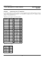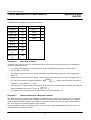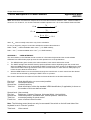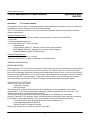
1
APPLICATION NOTE
Circuit description of CCM420
monitor
AN97032
Philips Semiconductors
Circuit description of CCM420 monitor
Application Note
AN97032
Abstract
2
The CCM420 demo monitor is a full I C-bus controlled 17” colour monitor. It’s extensive geometry control and
excellent video performance with a high level of integration make it a high-performance monitor at moderate
cost and easy application.
2
Purchase of Philips I C components conveys
2
a license under the I C patent to use the com2
ponents in the I C system, provided the system
2
conforms to the I C specifications defined by
Philips.
© Philips Electronics N.V. 1997
All rights are reserved. Reproduction in whole or in part is prohibited without the prior written consent of the
copyright owner.
The information presented in this document does not form part of any quotation or contract, is believed to be
accurate and reliable and may be changed without notice. No liability will be accepted by the publisher for any
consequence of its use. Publication thereof does not convey nor imply any license under patent- or other industrial or intellectual property rights.
2
Philips Semiconductors
Circuit description of CCM420 monitor
Application Note
AN97032
APPLICATION NOTE
Circuit description of CCM420
monitor
AN97032
Author:
Hans Verhees
Philips Semiconductors Systems Laboratory Eindhoven,
The Netherlands
Keywords
Colour Monitor
Geometry control
EHT supply
2
I C control
17” HiRes
Number of pages: 50
Date: 97-10-14
3
Philips Semiconductors
Circuit description of CCM420 monitor
Application Note
AN97032
Summary
This application note includes a brief description of the circuits of the CCM420 demo monitor excluding the
video part (see references); complete circuit diagrams plus printed circuit board lay-out and parts list as well as
hints on the pcb lay-out are given. Debugging of the main printed circuit board and alignment in a complete
2
monitor is also included in the report. Highlights of this design are the I C controlled monitor deflection controller
2
TDA4854, I C controlled video controller TDA4885, full-bridge vertical deflection booster TDA8354, monitor
Microcontroller P83C181* and the control software CCM420S. Combining this board with the CMT
M41EHN323X145 and video board completes the CCM420 monitor.
* The Microcontroller P83C181 is pruned. It can be replaced by the P83C180. This device however has 42 pins
(additional DACs are included) which requires a redesign of the pcb. See also appendix CICT IC newsletter no.
17
4
Philips Semiconductors
Circuit description of CCM420 monitor
Application Note
AN97032
CONTENTS
1. INTRODUCTION .......................................................................................................................................... 7
1.1 CCM420 Specification ........................................................................................................................... 8
1.2 List of abbreviations............................................................................................................................... 9
2. BLOCK DIAGRAM...................................................................................................................................... 12
3. CIRCUIT DESCRIPTIONS.......................................................................................................................... 14
3.1 Switched mode power supply .............................................................................................................. 14
3.2 Microcontroller..................................................................................................................................... 14
2
3.3 I C-bus autosync deflection controller for PC/TV monitors TDA4854 .................................................... 14
3.3.1 Brightness uniformity .................................................................................................................. 15
3.4 Horizontal deflection output stage ........................................................................................................ 15
3.4.1 B+ supply ................................................................................................................................... 15
3.4.2 Line driver and output stage........................................................................................................ 15
3.4.3 Linearity and S-correction control................................................................................................ 15
3.5 Vertical deflection output stage ............................................................................................................ 16
3.6 EHT supply.......................................................................................................................................... 16
3.6.1 Grid 1 supply .............................................................................................................................. 17
3.6.2 Grid 2 supply .............................................................................................................................. 17
3.6.3 Focus supply .............................................................................................................................. 17
3.7 Rotation circuit..................................................................................................................................... 17
3.8 Sound circuit........................................................................................................................................ 17
4. CIRCUIT DIAGRAMS ................................................................................................................................. 18
4.1 Last minute changes............................................................................................................................ 18
5. PARTS LIST............................................................................................................................................... 25
5.1 Resistors and potentiometers .............................................................................................................. 25
5.2 Capacitors ........................................................................................................................................... 28
5.3 Transistors .......................................................................................................................................... 29
5.4 Diodes................................................................................................................................................. 30
5.5 Integrated circuits ................................................................................................................................ 31
5.6 Wire-wound components ..................................................................................................................... 31
5.7 Miscellaneous...................................................................................................................................... 31
6. PRINTED CIRCUIT BOARD LAYOUT........................................................................................................ 33
6.1 Lay-out hints........................................................................................................................................ 33
7. ALIGNMENT PROCEDURE ....................................................................................................................... 38
7.1 Equipment ........................................................................................................................................... 38
7.2 Alignment ............................................................................................................................................ 38
8. DEBUGGING PROCEDURE....................................................................................................................... 40
9. REFERENCES............................................................................................................................................ 42
5
Philips Semiconductors
Circuit description of CCM420 monitor
6
Application Note
AN97032
Philips Semiconductors
Circuit description of CCM420 monitor
1.
Application Note
AN97032
INTRODUCTION
2
The CCM420 demo monitor is a full I C bus controlled monitor. Extensive geometry control, a very wide deflection frequency range (horizontal: 15 - 84 kHz; vertical: 50 - 160 Hz), wide bandwidth video channels (maximum
pixel rate 180 Mhz) with perfect grey scale tracking, a full mains range supply combined with complete software
control result in a monitor with outstanding specifications while maintaining an economic design.
The CCM420 demo monitor is meant to show the latest products of Philips Semiconductors and Philips Components. Key components are:
•
monitor microcontroller P83C181
•
CCM420S monitor control software
•
I C-bus autosync deflection controller for PC/TV monitors TDA4854
•
I C-bus controlled octuple eight bit DAC TDA8447
•
full bridge vertical booster TDA8354
•
150 Mhz video controller with I C-bus TDA4885
•
hybrid video output stage CR6927
•
low power line driver transformer CU15/35
•
monitor line deflection transistor BU2532AL
•
DC controlled linearity corrector PE4025/01
•
EHT transformer AT2097/M1
•
0.27 mm dot triplet pitch CRT M41EHN
•
Optionally available is an active convergence control circuit with the vector processor TDA4845
2
2
2
The monitor microcontroller P83C181 has a DDC interface, auto-sync detection and a hardware sync processor. The DDC interface is DDC2AB compliant. The hardware mode detector has 12 bit resolution for the horizontal and vertical frequency, polarity detection and sync presence detection. The built-in sync processor also
has a free-running mode. In this design the microcontroller runs with newly developed software CCM420S. This
software allows extensive user control of geometry and colour adjustment.
2
The autosync deflection controller for PC/TV monitors TDA4854 is fully I C-bus controlled and in this application
operating with a horizontal frequency range of 15 to 90 kHz (maximum 150 kHz; maximum ratio 6.5 :1). It allows very extensive control of geometry both horizontally and vertically, built-in B+ control part and focus section. Built-in soft-start as well as controlled shut down for B+ and deflection drive signals safeguard the output
stages at power-up and power-down, while smooth caption of horizontal frequency during mode-changes ensures adequate protection of the line output stage. The B+ control part is used in the feed-forward mode without
any feedback (omitting loop stability problems). The focus section has a fixed correction for the delay in the high
voltage output stage.
The vertical booster is the newly introduced TDA8354. This is a LVDMOS full bridge current driven output stage
for 3.2 Ampere peak-peak maximum and a flyback supply voltage of 68 Volt maximum.
The horizontal output stage is separated from the EHT supply to get maximum front of screen performance.
The line driver uses a low-power design with the CU15/35 driver transformer and a high-speed switching line
output transistor BU2532AL. To obtain optimum scan performance six S-correction switches and a newly designed DC-controlled linearity corrector PE4025/01 are used.
The separate EHT supply section is synchronised with the horizontal deflection and uses a dedicated transformer AT2097/M1. Incorporated in this application are a number of protections to prevent spot burn-in.
7
Philips Semiconductors
Circuit description of CCM420 monitor
Application Note
AN97032
The M41EHN tube is fitted with a rotation control coil. The tilt adjustment in this monitor allows an additional
control of the bottom line (Tilt respectively NS trapezium).
Front of screen performance is further enhanced by means of a brightness-uniformity circuit which can be
2
switched on/off via I C.
1.1
CCM420 Specification
General
•
Mains voltage
90 - 264 Volts AC
•
Mains frequency
50 - 60 Hz
•
Power consumption
100 W typical
•
Operating ambient temperature
10 °C to 40 °C
•
Weight
20 kg
•
Dimensions (W x H x D)
417 x 426 x 446 mm
3
Picture tube
•
Type
M41 EHN 323 x 145 2F01R
•
Horizontal deflection impedance
130 µH (max. hor. freq. 84 kHz)
•
Vertical deflection impedance
7.7 Ω
•
Dot triplet pitch
0.27 mm
•
Recommended active screen area 312 x 234 mm
•
Anode voltage
2
26.0 kV
Video
•
Maximum dot rate
180 Mhz
•
Video input signal
700 mVpp linear via three BNC inputs
•
Video input impedance
75 Ω
•
Horizontal shift range
> ±12.5 mm
•
Vertical shift range
> ±12.5 mm
•
Horizontal amplitude
•
Vertical amplitude
< 160 mm to > 240 mm
•
Reference white point
x = 0.313; y = 0.329 (D6500)
•
White point deviation
∆x < 0.01; ∆y < 0.01
•
Grey scale tracking
∆x < 0.02; ∆y < 0.02
< 210 mm to > 340 mm
Sync signals
•
Inputs
Separate Horizontal/Composite and Vertical inputs via BNC
8
Philips Semiconductors
Circuit description of CCM420 monitor
•
Level
TTL
•
Polarity
Positive or negative
•
Horizontal frequency
15 to 84 kHz
•
Vertical frequency
50 to 160 Hz
Application Note
AN97032
User interface
•
Control
Five button keyboard plus USER/SERVICE switch
•
Indication
On Screen Display with 4 lines of 12 characters
1.2
List of abbreviations
A1
Auxiliary 1
A2
Auxiliary 2
A3
Auxiliary 3
A4
Auxiliary 4
AGCDIS
Automatic gain control in vertical oscillator enabled/disabled
ASDC
Auto-Sync Deflection Controller
BB
Blue Black level
BG
Blue gain
Black Lvl B Blue channel black level control register in the TDA4885
Black Lvl G Green channel black level control register in the TDA4885
Black Lvl R Red channel black level control register in the TDA4885
BLKDIS
Vertical protection at ‘Clamping/blanking’ and ‘Horizontal unlock’ enabled/disabled in the TDA4854
Brightness Brightness control register in the TDA4885
CLAMP
Selection of trailing/leading edge horizontal clamping pulse in the TDA4854
Contrast
Contrast control register in the TDA4885
CRT
Cathode Ray Tube
CT
Colour temperature
DDC
Display Data Channel
DISO
On Screen Display enabled/disabled in the TDA4885
DISV
Video signals enabled/disabled in the TDA4885
DPMS
Display Power Management Signalling
EHT
Extreme High Tension
ENN
Fast blanking pulse for On Screen Display
EW
East-West
FHMULT
East-West output tracking with / independent of horizontal frequency in the TDA4854
9
Philips Semiconductors
Circuit description of CCM420 monitor
FPOL
Selection of positive / negative feedback polarity in the TDA4885
G2
CRT grid 2
Gain B
Blue channel gain control register in the TDA4885
Gain G
Green channel gain control register in the TDA4885
Gain R
Red channel gain control register in the TDA4885
GB
Green Black level
GG
Green gain
H
Horizontal
H-corner
Horizontal corner control register in the TDA4854
H-focus
Horizontal focus control register in the TDA4854
H-moiré
Horizontal Moiré control register in the TDA4854
H-paral
Horizontal parallelogram control register in the TDA4854
H-pin
Horizontal pincushion control register in the TDA4854
H-pin-bal
Horizontal pin-balance control register in the TDA4854
H-pos
Horizontal position control register in the TDA4854
H-Rot
Horizontal Rotation or Tilt control register in the TDA8447
H-size
Horizontal size register in the TDA4854
H-trap
Horizontal trapezium control register in the TDA4854
HB
Horizontal Pin-balance
HBC
Horizontal pin-balance enable/disable
HC
Horizontal Corner
HF
Horizontal focus
HL
Horizontal linearity
Hlin
Horizontal linearity control register in the TDA8447
HP
Horizontal Pincushion
HPC
Horizontal pincushion enable/disable
HT
Horizontal Trapezium
2
Application Note
AN97032
IC
Inter IC
LVDMOS
Low Voltage Depletion Metal Oxide Semiconductor
MOD
Horizontal and vertical moiré cancellation enabled/disabled in the TDA4854
NS
North-South
NStrap
North-South trapezium control register in the TDA8447
OC
On Screen Display contrast
Oh
On Screen Display Horizontal position
OSD
On Screen Display
OSD Ctrst
On Screen Display contrast control register in the TDA4885
Ov
On Screen Display Vertical position
10
Philips Semiconductors
Circuit description of CCM420 monitor
PA
Parallelogram
PEDST
Pedestal blanking enabled/disabled in the TDA4885
RB
Red Black level
RG
Red gain
SCK
Serial clock
SDI
Serial data
SMPS
Application Note
AN97032
Switched Mode Power Supply
SMPTE
Society of Motion Picture and Television Engineers
SOFTST
Softstart control bit in the TDA4854
STDBY
Standby control bit in the TDA4854
TI
Tilt
TVMOD
TV mode at Fmin activated/de-activated in the TDA4854
USB
Universal Serial Bus
V
Vertical
V-focus
Vertical focus control register in the TDA4854
V-lin
Vertical linearity control register in the TDA4854
V-lin-bal
Vertical linearity balance control register in the TDA4854
V-moiré
Vertical Moiré control register in the TDA4854
V-pos
Vertical position control register in the TDA4854
V-size
Vertical size control register in the TDA4854
VB
Vertical linearity balance
VBLK
Selection of duration of vertical blanking pulse in the TDA4854
VESA
Video Electronics Standard Association
VF
Vertical focus
Vg1
Voltage on grid 1 of the CRT
Vg2
Voltage on grid 2 of the CRT
Vg2
Grid 2 voltage control register in the TDA8447
VL
Vertical linearity
VLC
Vertical linearity balance control enabled/disabled in the TDA4854
VOVSCN
VGA vertical size control bit in the TDA4854
VPC
Vertical position and Horizontal trapezium control enabled/disabled in the TDA4854
VSC
Vertical linearity and Horizontal corner corrections enabled/disabled in the TDA4854
VT
Vertical trapezium
11
Philips Semiconductors
Circuit description of CCM420 monitor
2.
BLOCK DIAGRAM
12
Application Note
AN97032
Philips Semiconductors
Circuit description of CCM420 monitor
Application Note
AN97032
Remarks to the block diagram:
1.
The Dynamic convergence circuit is optional. The Vector Processor TDA4845 is not commercially available.
2.
Due to time limitation and mechanical restrictions the sound part is, although present in the printed circuit
board layout, not inserted and therefor not operational.
13
Philips Semiconductors
Circuit description of CCM420 monitor
3.
3.1
Application Note
AN97032
CIRCUIT DESCRIPTIONS
Switched mode power supply
The SMPS is preceded by a mains harmonic reduction coil (L1: TU305b2) in order to reduce mains harmonics
distortion. This coil is short-circuited for mains voltages below 175 VAC (T6, T7 and TH2).
An additional connector ‘USB-supply’ is present for an optional USB supply (under development; available
???;see references).
In this SMPS only DPMS level 1 is realised resulting in a burst-mode operation of the SMPS. Transistor T10
and T11 act as comparator to control the burst mode. In this burst mode the mains input power reduces to less
than 2.5 W. In case the USB supply is present, the SMPS is switched-off completely while the microcontroller
supply is maintained from the USB supply part (header X3).
2
DPMS level 2 is realised by using the Standby-mode of the TDA4854 activated via I C bus.
Overcurrent protection is achieved by means of resistors R32, R33, and R34 connected to pin 13 of the
TDA8380. In case of continuous short circuit diodes D32 and D33 provide extra protection by increasing the
delay time before the next slow-start is initiated.
The only adjustment is the 185 Volt output by means of potentiometer P1.
The output voltages of the supply are:
185 V horizontal deflection and EHT output stages; reference voltage for Vg2.
78 V video output stages;
18 V driver stages, rotation circuit and 12 Volt stabiliser;
11 V vertical deflection output stage, 5 Volt stabiliser and heater current;
-18 V rotation circuit.
3.2
Microcontroller
2
The microcontroller P83C181 controls all adjustments in the complete monitor by I C bus. The only two adjust2
ments not accessible by I C bus are the “SMPS 185 Volt” and the “EHT 26.0 kV”. The user interface consists of
a five button keyboard and an On-Screen-Display.
Communication with the OSD controller on the video board is via a high speed interface bus (signals ENN, SDI
and SCK).
In normal operation the user has only access to the first two levels of the software program. The first level being
the video mode information displaying horizontal and vertical frequencies and mode number/identification. The
second level gives access to control the brightness, contrast, degaussing, horizontal and vertical moiré cancellation, picture position and size. Brightness and contrast control can be directly accessed by respectively menu
u/d buttons and cursor u/d buttons.
In the service mode (jumper J301 closed; service switch down on the front keyboard) the higher levels for control of colour (black levels, gain, etc.) and geometry (pin-cushion, pin-balance, trapezium, etc.) can be accessed.
3.3
2
I C-bus autosync deflection controller for PC/TV monitors TDA4854
The TDA4854 is applied here in a basic configuration. This means HSMOD, VSMOD and ASCOR pins are not
used (separate horizontal deflection and EHT supply; no DC shift circuit for horizontal deflection). ASCOR is
internally connected to PLL2 (bit ACD = 1).
14
Philips Semiconductors
Circuit description of CCM420 monitor
Application Note
AN97032
The horizontal oscillator can be synchronised in the frequency range from 15 to 85 kHz (determined by resistors
R350 and R351 and capacitor C318). The value of R350 and R351 can be determined according to the equations in appendix 3.
The B+ section is fed with the EWDRV signal from pin 11 with the FHMULT bit = 0 (multiplication with the frequency is achieved in the output stage). The sawtooth generator uses a current source to minimise influence of
the supply voltage. Capacitor C312 must have a low temperature coefficient (preferably NP0) to minimise temperature effects. Capacitor C314 must be placed as close as possible to pins 3 and 7 to minimise EMS.
The HUNLOCK signal is used as interrupt for the microcontroller in case of a mode change and insertion of
vertical blanking pulses on the CRT grid 1 voltage (12 Volt peak). Via diode D303 the sawtooth generator of the
North-South trapezium circuit is reset.
3.3.1
Brightness uniformity
A brightness uniformity signal can be extracted from the focus signal on pin 32. The signal is buffered by T304
to drive the modulation inputs of the TDA4885 video preamplifier. The brightness uniformity function can be
2
switched on and off by I C control via IC303 register 4 and T305 (Brightness uniformity OFF: register contents
set to ‘255’; Brightness uniformity ON: register contents set to ‘0’).
3.4
Horizontal deflection output stage
The horizontal deflection output stage consists of three main parts:
3.4.1
B+ supply
The signal BDRV from the TDA4854 is buffered (T400/T401) and then fed to the PMOS output transistor. Diode
D401 and resistor R403 are added for protection.
3.4.2
Line driver and output stage
The line driver stage is built around TR401. The use of the BU2532AL results in a low power driver stage
(typically 1.8 W) capable of driving the line output transistor over a wide frequency range. The stage is designed
to operate from 15 to 90 kHz.
The diode D405 in the collector of T403 BU2532AL ensures the high efficiency of the driver stage. Here a
Schottky-barrier type is used for it’s low forward voltage drop. In fact any diode capable of handling the peak
deflection current can be used but forward voltage drop should be minimal (in order not to deteriorate linearity).
Maximum reverse voltage for D405 is the forward recovery voltage of the deflection flyback diode D404.
See also application note ETV/AN97002
3.4.3
Linearity and S-correction control
Horizontal linearity is controlled with a newly designed DC-controlled linearity corrector PE4025/01. The control
2
coil is current driven by T405 under I C control via IC303 register 7.
S-correction is performed with five switches for the frequency range of 30 to 90 kHz and one extra switch for
the TV mode.
The S-correction capacitors are switched according to the following table:
15
Philips Semiconductors
Circuit description of CCM420 monitor
Freq.range
< 30 kHz
30 - 34 kHz
34 - 37 kHz
37 - 45 kHz
45 - 53 kHz
53 - 61 kHz
61 - 65 kHz
65 - 71 kHz
71 - 78 kHz
78 - 85 kHz
> 85 kHz
3.5
C423
47 nF
x
x
x
x
x
x
-
C417
120 nF
x
x
x
x
x
-
C418
220 nF
x
x
x
x
x
-
Application Note
AN97032
C419
470 nF
x
x
x
-
C420
1.2 µF
x
x
x
x
-
C421
5.6µF
x
-
Vertical deflection output stage
The vertical deflection output stage is the new full-bridge current driven booster TDA8354 which has output
stages with low saturation voltage allowing low power dissipation (depending upon power supply voltage).
The circuit around transistor pair T418 / T419 is used as interface for the active convergence control circuit
(optional).
3.6
EHT supply
The EHT supply is in fact a flyback generator with controlled supply voltage by means of a B+ down converter
to enable stabilisation of the EHT output voltage. In order to prevent any kind of visible interaction with the
horizontal deflection the EHT generator is synchronised with the horizontal deflection Although the flyback of
the EHT generator lags the flyback of the horizontal deflection with ≈ 3µs. The high-voltage transformer
AT2097/M1 is specially designed for this EHT generator: primary inductance 450 µH, circuit flyback time 3.3 µs,
maximum operating frequency 84 kHz. The extreme high tension output voltage is 26.0 kVolt with a maximum
average load current of 700µA (short term peak 1.5 mA).
The flyback transistor T109 BUT11A is driven by a one-shot circuit built around IC102A. Using the well defined
sawtooth of the PWM controller IC101 and it’s temperature stable reference voltage an accurate pulse is generated. The pulse length is defined by two more or less fixed intervals:
1.
storage time of the flyback transistor (≈ 1.2 µs)
2.
flyback time of the output stage (≈ 3.4 µs)
Increasing this period with an extra wait interval for safety a total pulse length of 7 µs is required.
The reference voltage for the X-ray sensor IC102B is increased with a small part of the supply voltage to prevent false triggering at power-up. This is achieved by means of R116 and R117.
The EHT output voltage is adjusted with potentiometer P101.
The following protections are included:
•
No horizontal deflection (horizontal flyback voltage below 500 Voltpp): EHT generator stops; automatic soft
start when horizontal deflection starts again.
•
Overvoltage / X-ray: EHT generator is stopped and latched in an off-mode; a restart is only possible after a
mains switch-off and on again.
16
Philips Semiconductors
Circuit description of CCM420 monitor
•
Application Note
AN97032
Overcurrent: First level protection is here the beam-current level limiter reducing the contrast of the video
stages. Second level is the maximum duty-cycle of the UC3843 (≈99%) that cannot be handled by the AC
coupling of the PMOS output stage (T119 will not be driven in conduction anymore); in this situation the
generator part will continue operating but the output voltage will drop to zero. Restart is only possible after
a mains switch-off and on again.
3.6.1
Grid 1 supply
The CRT grid 1(Vg1) voltage is fixed at -62 Volt DC with vertical blanking pulses of 12 Volt pp. Protection by
pulling Vg1 to -200 Volt is activated in case of absence of horizontal deflection, HUNLOCK signal continuously
high, absence of ‘11Volt’ supply voltage and/or a high vertical guard signal.
3.6.2
Grid 2 supply
The CRT grid 2 (Vg2) voltage is generated using a high voltage DC amplifier. Its input is driven by a DAC output
2
of the TDA8447 to allow I C bus control.
The range is 280 to 665 Volt.
3.6.3
Focus supply
The dynamic focus voltage from the output of the TDA4854 is amplified by a high-voltage amplifier and then
connected to the coupling capacitor in the EHT transformer.
Resistor R173 and diodes D132 and D133 prevent cross-over distortion of the output stage.
3.7
Rotation circuit
The circuit for driving the rotation coil on the CRT is extended with a sawtooth generator (IC201 B) to allow
separate control of the top and bottom horizontal line. So the adjustment sequence is to align the top line with
the tilt control (the complete picture is rotated with this adjustment) and then the bottom line can be aligned with
the NS-trapezium adjustment.
3.8
Sound circuit
The sound part is a 2 x 1 Watt output stage with DC volume control TDA7053A. In this application 25 Ω speakers should be used.
Note: Due to mechanical problems it was not possible to implement the sound input connectors and the speakers in the cabinet. Therefor the circuit is not present in the demo monitors although the lay-out is prepared for it.
17
Philips Semiconductors
Circuit description of CCM420 monitor
4.
Application Note
AN97032
CIRCUIT DIAGRAMS
On the next pages the following circuit diagrams are presented:
−
Switched mode power supply;
−
Microcontroller plus deflection controller part;
−
Horizontal and vertical deflection output stages;
−
CRT grid supply circuits: Vg1, Vg2, focus and dynamic focus amplifier, EHT supply;
−
Rotation and sound.
4.1
Last minute changes
When debugging the final monitor a few small changes were necessary to obtain maximum performance.
Component
number
C8
C12
C414
D19
Old value
New value
Reason
470 µF / 25 V
3.9 pF / NP0
(not present)
BZX79C15
220 µF / 25V
18 pF / NP0
4.7 µF / 200 V
BZX79C18
D90
D91
D408
R50
R62
(not present)
(not present)
(not present)
270 Ω / PR03
120 kΩ / SFR25
BZX79C15
BZX79C15
BYD73D
270 Ω / AC04
180 kΩ / SFR25
R344
R353
R390
R391
R416
R432
R441
56 kΩ / SMD 0805
8.2 kΩ / SMD 0805
(not present)
(not present)
(not present)
2.7 kΩ / PR02
2.7 kΩ / PR01
33 kΩ / SMD 0805
3.3 kΩ / SMD 0805
3.3 kΩ / SFR25
3.3 kΩ / SFR25
2.2 kΩ / PR02
2.2 kΩ / PR02
2.2 kΩ / PR01
Decrease start-up time SMPS
Current sense SMPS
Horizontal ringing damper
Increase output power during “OFF”
mode
Protection of T12 during mains switching
Protection of T12 during mains switching
Horizontal ringing damper
PCB may overheat
Increase output power during “OFF”
mode
Pin-cushion range
Jitter
See text and drawing below
See text and drawing below
Horizontal ringing damper
Horizontal ringing
Vertical flyback
Zenerdiodes D90 and D91 have to be connected back-to-back (i.e. cathodes
tied together) and the two anodes must be connected to Gate respectively
Source of T12. In the circuit diagram on the right one can see how it looks.
T12
The two zenerdiodes D90 and D91 are placed on the copperside of the board.
D90
D91
18
Philips Semiconductors
Circuit description of CCM420 monitor
Application Note
AN97032
An additional damper for the horizontal deflection cannot be combined
with the largest S-correction capacitor. Therefor an additional damper
is necessary as drawn in the circuit diagram on the left hand side.
C414
4u7
200V
T415
R434
Add this resistor:
SFR25; 3.3 kOhm
R31
R6
R5
Add this resistor:
SFR25; 3.3 kOhm
TH1
XT301
R315
X303
T1
R313
R314
C305
C304
R439
BYD73D
R416
2k2
PR02
R420
D408
C416
180n
630VDC
R4
SW1
X1
The outputs P0.5 pin 16 and P0.7 pin 14 of IC304
respectively signal “DEGS” and “DPMS” should be
equipped with a pull-up resistor of 3k3 to +5 Volt.
These resistors are not present in the lay-out. Best
location to add these resistors is near R5 and R6
according to the drawing on the right:
The transistors BC375b and BC376 will be pruned. Best replacements for these types are BC337 respectively
BC327. No further modifications are necessary.
Transistor T124 is not correctly placed in the printed circuit board design : collector and emitter connections are
interchanged on the board. The circuit diagram and parts list however are correct.
C124 and C403 are replaced with 27 nF / 250 Volt due to temporary unavailability of 22 nF / 250 Volt.
The following component on the video board has to be changed:
Video board:
Component
number
R29
PCB track
Old value
New value
Reason
1.0 Ω / SFR16
3.3 Ω / SFR16
Cut track to pin 3 of
connector 1
Heater tension
+5 Volt of Video must be disconnected
of + 5 Volt of main board.
19
T1
R4
96126
BC548
X1
220n
275V~
7
2
C2
9
3
TH1
MOC2A60_5
D2
C1
1M
R1
220n
275V~
R2
R3
270E 2E7
PR01 AC04
AT4043/20
250V~
3
D7
BZX79
C6V2
NFR25H
R16
18k
R35
5k1
R8
1k5
D13
BZX79C5V6
2
TH2
MOC2A60_5
7
9
L1
TU305B2
T2
BSP145
R10
10E
R9
10E
R18
100k 5k1
R17
R37
1k
R28
47k
R39
820E
R40
22k
R38
T6 T7 36k
BC548
BC548
R36
100E
680p
C10
R13
1M
T3
BC547
R12
1k
BT151-500R
D6
D8
BZX79
C33
R41
680E
C13
10u
50V
3p9
C12
0E47
NFR25H
R34
R33
0E33
NFR25H
NFR25
1N4148 R32
15k
D32
C11
4u7
63V
IC1
TDA8380A
R20
56E
R15
220k
R14
110k
C9
220u
400V
R76
R42
15E
22E
NFR25
BYD33D
4E7
NFR25
R22
C17
2n2
R24
1k
R66
10E
NFR25
D9
R65
10E
NFR25
D31
C18
R43
1k2
R78
9
7
8
D17
R
1N4148 T8
BC548
DPMS1
5V
R46
1k2
4k7
C14
2n2
R47
C19
10n
D26
BYD73D
D23
D24
D25
BYD33G
C38
680p
BYR29-800
R50
270E
PR03
10k
T9
BC548
R45
R52
100E
OC1
CNX82A
BYD73D
D22
BYV28/100
R48
1k
15
13
12
11
17
18
14
4
3
16
5
R44
330E
D16
T14
22n
C15
4n7 250V~
6 TR2 10
BI-COLORLED
GR
12V
BC548
D15
1N4148
1N4148
D14
R30
1k
T5
W9NA80
R25
220E
PR02
C20
2n7
220p
500V 500V
C39
R49
4M7 VR37
C21
L3
L4
10u
100p
R59
100k
R68
1k
R56
100k
10u
L6
L5
10u
R61
24k
BC558
T11
BC558
T10
R57
18k
2k2
D19
BZX79
C15
120k
R64
180k
R62
D18
1N4148
185V
P1
1k
R54
5k1
5V
C35
4n7
R53
150k
VO
-18V
11V
18V
78V
C29
470u
25V
R51
C28
1000u
16V
T13
BC548
C27
470u
25V
2AF
D20
BZX79
C6V2
R74
1k
1N4148
D29
R67
185V
10E
NFR25
F2
D21
BZX79
C6V2
5V
1N4148
D28
2AF
C26
470u
25V
F4
2AF
C25
1000u
16V
470u L7
25V
F3 10u
C24 10u
C23
47u
100V
C36
R58
39k
L2
C22 10u
150u
250V
VO
2
IC2
7812
R75
T17
BC548 47k
BSN274
R63
180E
NFR25H
T12
R55
100E
C34
1000u
16V
D30
1N4148
11V
1
C30
68u
16V
C32
68u
16V
12V
DPMS1
5V_USB
5V
X3
3p-HEADER
C31
330n
IC3
78L05
3
Circuit description of CCM420 monitor
Line Power
90-260V~
F1
2A
SLOW
TR1
250V~
220n
C4 275V~ C3
2n2
2n2
SW1
2n2
D1
2n2
C5
D3
C7
D4
C6
8
9
R6
470E
7
10
R5
39k
6
11
C8
470u 25V
R11
10E AC05
D33
4xBYW54
4
R7
150k
5
12
2
15
D5
BYD13J
BYD33K
5V
1N4148
13
3
14
1
16
100k
PR01
470p 1kV
DEGS
R31
20
390E
AC04
D10
USB-supply
BYD33M
1
Philips Semiconductors
Application Note
AN97032
21
R313
100E
100E
J301
R314
DEGS
C305
100p
C304
100p
100E
R315
P0.5
P0.6
P0.7
VsyncOUT
VsyncIN
P1.6
HsyncOUT
HsyncIN
Vss
Vdd
ADC0
P3.3
P0.4
P0.3
P0.2
P0.1
P0.0
resetOUT
P83C181
XTAL2
XTAL1
INT1not
SDA1
R324
R323
R322
R321
R320
R317
R316
100E
100E
100E
100E
100E
100E
R318
100E
100E
R306
10E
100E
100E
R326
4k7
R327
22k
IC303
4u7
16V
C307
R328
4E7
SDA
SCL
open=VGAselftest
2n7
J302
C306
100E
R319
R325
4k7
C303
68u
16V
R307
R308
SDA_DDC
5V_DDC(n.c.)
SCL_DDC
DDC
100E
100E
R332
R331
R330
4k7
4
3
2
1
100p
100p
C308 C309
R329
4k7
5V
X304
4k7
R364
4k7
SC4
SC3
SC2
SC1
SC0
Keyb
CLMP
VDEF1
VDEF2
HDRV
BDRV
INTN(USB)
SDA_DDC
10n
T305
BC548
6
5
4
3
2
1
R333
1k
4E7
R334
R361
6k8
BC548
R360
27k
12V
X305
12V
USB
C323
R363
10k
FCSD
SModeN
Keyb
5V
SCL_DDC
HLIN
NSTR
HROT
Vg2D
R365
100E
R310
68u
16V
C311
R343
R342
R341
8k2
100E
100E
2n2
C312
T301
100E
R337
2k2
BC558
C5V6
D301 BZX79 R336
R362
2k2
T304
(n.c.)
INTN
SDA
5V_USB
SCL
CRT_digital
100p
C315
HFLB
1
2
3
4
8
7
6
5
4
3
2
1
100p
C316
10n
C314
27k
R339
X303
X307
R346
R345
100E
100E
56k
R344
10k
R340
10p
C310
R338
1k5
SCK
SDI
ENN
SDA
5V
SCL
CRT_supply
HSYNC
VSYNC
VOUT1
VOUT2
CLBL
R309
R359
12V
IC305
HUNLOCK
SCL
SDA
ASCOR
n.c.
VAGC
VREF
VCAP
Sgnd
HPLL1
HBUF
HREF
HCAP
HPLL2
i.c.
FOCOS
10k
R351
C319
C320
6k8
R358
R356
12k
12V
100E
100E
BC548
R355
100n
R354
T303
R357
4k7
5k23 1%
100n
R352
22k
R349
270E
T302
BC548
R366
100E
C317
12n
C318
10n
R350
R348
10k
185V
-18V
VSync
732E 1%
R347
220E NFR25
14
13
12
11
1N4148
D303
R353
3k3
100n
C321
C324
100n
3n3
-18V
18V
HBLNK
VSaw
SDA
SCL
VRotS
VBLNK
HUNLOCK
SCL
SDA
FCSD
C322
12
11
HBLNK
(n.c.)
(n.c.)
(n.c.)
(n.c.)
(n.c.)
10
8
7
6
5
4
3
2
1
10
X306
9
HSync
Vg1
11V
HBLNK
CLMP
11V
78V
BCL
PeCoMa
9
8
7 15E PR03
6
5
4
3
2
1
TDA4854
EWDRV
Vcc
Dgnd
HDRV
PGND
BDRV
BIN
BSENSE
BOP
XRAY
HFLB
X301
Circuit description of CCM420 monitor
DPMS1
closed=service_mode
SModeN
VSync
HSync
R312
22k
P2.0
P2.1
SCL1
16kHz
SCL0
P1.7
P2.2
IC304
100E
100E
SDA0
P2.5
R305
R304
P2.3
XT301
12MHz
IC302
SCK
5V
IC301
P2.4
C302
68u
16V
10E
R302
C301
68u
16V
10E
5V
4
3
2
Keyboard
TDA8447
1
BRIGHTNESS
UNIFORMITY
R301
PCE8582
C2E
PCE8582
C2E
SDI
ENN
5V
X302
Philips Semiconductors
Application Note
AN97032
HDRV
HFLB
BDRV
12V
18V
22
100E
R410
R436
22E
R435
22E
NFR25
100E
R400
10u 63V
D407
1N4148
C410
R409
680E
C422
68u
16V
R408
33E
D406
C431
47u
25V 1N4148
BZX79
D409 C6V8
18V
R411
18k
10n
C409
T404
BC375b
C408
470n
T401
BC376
TR401
CU15/35
R407
220E
4
3
33n
250V
C401
D401 47u
1N4148 25V
T400
BC375
C400
1
2
R438
150k
7
1
-HDFEL
R421
3k9
T417
BC548
SC0
R439
10k
R422
10k
SC1
R442
0E47
NFR25
47u
50V
C424
Vguard
10E
R413
330u
16V
C425
T409
BC548
R424
47k
R426
150k
VpB
VoB(-)
IC401
TDA8354
VoA(+)
VpA
L403
10uH
T411
BC548
R427
47k
R429
150k
X402
SC3
R428
10k
T410
BUK445
100B
C419
470n
250V
VertDeflCoil
330E
gndA
C426
10n
Vflb
R446
1E8
gndB
R447
R445
1E8
R444
2k0
R443
3k3
Vcon
HLIN
VM
SC2
R425
10k
T408
BUK445
100B
C418
220n
250V
R415
27E
PR01
T405
BC548C
R458
220E
PR01
T407
BC548
R419
47k
R423
150k
C412
4n7
250V
T406
BUK445
100B
270E
PRO3
R414
T416
BUK445
100B
R420
1k
250V
L402
C411
4n7
18V
D410
BZX79
C39
PE4015/01
47E
R412
11V
C417
120n
250V
R437
47k
R418
150k
BY
459F
D404
X401
STOCKO7
R440
5k6
C423
47n
400V
4n7
2kV
C406
+HDEFL
C403
22n
250V
Vguard
R441
2k7
PR01
11V
Icomp
Ii+
Ii-
C427
10n
T418
VSaw
VDEF2
VDEF1
16kHz
T415
BC548
R433
47k
12V
R434
10k
T414
BUK445
100B
C421
5u6
160V
R457
4k7
BC558
T419
R456
3k9
R454
330k
R455
3k9
BC558
C428
10n
T413
BC548
SC4
R431
10k
R430
47k
R432
2k7
PR02
C429
2n7
T412
BUK445
100B
C420
1u2
250V
C430
1n
R451 10k
R450 10k
R449 270k
185V
R453 100E
R452 100E
Circuit description of CCM420 monitor
5V
BYV99
D403
L401
1.2mH
U20 core
T403
BU2532AL
R405
47E
C405
47p
1kV
C416
180n
630VDC
C407
150n
R406
2E7
BZX79
C10
D402
T402
IRF9630
R404
10k
D405
1N5822
C404
2n7
100V
120E
R403
C402
150u
250V
185V
78V
Philips Semiconductors
Application Note
AN97032
23
R168
1k
HUnlock
-200V
T121
BC548
MPSA92
D128
1N4148
D129
1N4148
R171
1M
C129
22n
100V
R109
68k
560k
R110
R172
120k
47k
R119
51k
VBLNK
VG1
1N4148
C104
2n2
D105
C130
220n
250V
D134
BZX79
C4V7
D130
BZX79
C62
R170
T122
IC101
UC3843p
DIL8p
R169
1k
11V
820E
R107
3k3
T103
PH2369
1N4148
D127
330p
C102
470p
R167
10k
12V
100E
27p
100p
C103
R108
C136
C105
C106
3n3
1N4148
100n
D107
R133
270E
5k6
Vg2D
R135
24k
12V
LM393
3 IC102/A
2
1N4148
D109
D108
1N4148
D114
1N4148
56k
R122
R124
1
R159
1k
R129
3M3
R137
R139
36k
150k
R163
D135
BYD33D
T113
MPSA44
BZX79
C75
185V
500V
C112
2n7
1k
R132
D113
150k
R162
R136
150k
T111
BC375b
D112
BYD73D
100u
L101 D111 10V
6u8
BYD73D
C111
T109
BUT
11A
T108
BC376
T107
BC375
R130
3M3
C110
68u
16V
D110
T110 BZD23C5V1
BC375b
1M8
R138
1M5
T112
MPSA42
T106
PH2369
C128
68u
16V
27E
1k 1k
PR01
R126 R127 R128
68u
16V
3k3
C127
R125
R164
4E7
NFR25H
8
7
2k2
5 IC102/B
4
LM393
C135
47p
6
R117 680k
R165
100E
6E8
NFR25H
R115
X101
D117
5
6
*
1
2
4k7
R142
270k
R144
1M5
D118
BZX79C
6V2
R176
39k
2k2
R175
T115
MPSA44
T114
MPSA44
12V
D131
BAS32
R173
D132
1N4148
1k
D133
1N4148
R177
11k
D120
R145
8k2
100k
3k3
R149
R148
1k
C116
100n
R150
220k
R146
220k
C117
1n
1kV
16KHZ
BCL
12V
185V
R147
R151 13k
P101
22k
R154
47k
1N4148
R161
10K
C121
1u
63V
EHT
R156
3E3
NFR25
C126
10u
250V
T120
BC548
T123
BC548
R143
1M5
T117
MPSA44
T118
MPSA44
R152
1k
DF
1n
GF
GC
3n0 600M
GR
1n
R141
270k
10u
63V
C118
*
*
*
*
*
*
TR101 AT2097/M1
D116
BYD33M
-200V
C119
1u
250V
R153
100E
NFR25H
D121
BYD73G
BYD33M
1k
Vg2
1n5
22n
C124
BYV27-200
T119
IRF9630
D124
R155
L102 120E
PR01
10u
R157
10k
C123
D122
BYD33M
120E
R158
D125
BZX79
C10
R140
1kV
C120
4n7
1n BYV
1kV 26E
C122 D123
R131
2M7
33n
250V
C125
D126
1N4148
FCSD
12V
Circuit description of CCM420 monitor
Vguard
R179
15k
R178
47k
R166
3k3
HBLNK
R105
C107
4u7
63V
1N4148
D106
120k
100E
R112
R113
10k
R116
R118
C108
R114
10E
NFR25H
C109
100u
16V
C134 15p
4k3
R123
T124
BC548
12V
Philips Semiconductors
Application Note
AN97032
NSTR
VRotS
HROT
24
P201
10k
1
2
3
R227
100k
7
100n
3
2
1
R224
4k7
R
L
R223
4k7
R221
4k7
100n
C212
R206
R208
22k
R222
4k7
C213
68u
16V
LM358b
C216
SOUND
INPUT
220n
IC201/B
X204
C217
68u
16V
100n
C203
5
6
C204
180k
R205
BC558
T202
470n
C215
470n
C214
39k
6
2
8
4
3
14
R-in
Vol-R
Vol-L
L-in
100k
R209
2
4
33k
R212
8
C207
47u
25V
7
10
TDA7053A
IC202
5
IC201/A
LM358a
R211
43k
100E
R213
+
-
R-out
+
-
9
13
12
16
C209
47u
25V
L-out
1
R217
100E
NFR25H
T204
BC558
T203
BC548
R215
100E
NFR25H
1
3
SPEAKER
OUTPUT
X203
1
SPEAKER
OUTPUT
X202
-18V
3
(right)
(left)
R216
680E
47u
25V
C208
680E
R214
C210
47u
25V
3E3
R218
R220
22E
470n
C211
R219
1k
X201
3 Rotation coil
L = 65 mH
2
Rs = 125 ohm
1 I = +/-50 mA DC
+/- to -/+ 20 mA SAW
Circuit description of CCM420 monitor
X205
VOLUME
CONTROL
4E7
R228
+11V
56k
R207
1k8
56k
R203
R204
+18V
Philips Semiconductors
Application Note
AN97032
Philips Semiconductors
Circuit description of CCM420 monitor
5.
Application Note
AN97032
PARTS LIST
The parts list is only for the main board. No parts are listed to complete the CCM420 monitor.
5.1
Resistors and potentiometers
Note: Were no type is mentioned a SFR25 is used.
Number
R1
R2
R3
R4
R5
R6
R7
R8
R9
R10
R11
R12
R13
R14
R15
R16
R17
R18
R20
R22
R24
R25
R28
R30
R31
R32
R33
R34
R35
R36
R37
R38
R39
R40
R41
R42
R43
R44
R45
R46
R47
R48
R49
R50
Value
1M
270E
2E7
2322 622 96126
39k
470E
150k
1k5
10E
10E
10E
1k
1M
110k
220k
18k
100k
5k1
56E
22E
1k
220E
47k
1k
390E
15k
0E33
0E47
5k1
100E
1k
36k
820E
22k
680E
15E
1k2
330E
10k
1k2
4k7
1k
4M7
270E
Number
R51
R52
R53
R54
R55
R56
R57
R58
R59
R61
R62
R63
R64
R65
R66
R67
R68
R74
R75
R76
R78
R105
R107
R108
R109
R110
R112
R113
R114
R115
R116
R117
R118
R119
R122
R123
R124
R125
R126
R127
R128
R129
R130
R131
Type
PR01
AC04
PTC
NFR25
AC05
NFR25
PR02
AC04
NFR25
NFR25
NFR25
VR37
PR03
25
Value
2k2
100E
150k
5k1
100E
100k
18k
39k
100k
24k
120k
180E
180k
10E
10E
10E
1k
1k
47k
4E7
100k
100E
3k3
820E
68k
560k
120k
100E
10E
6E8
10k
680k
4k3
51k
5k6
56k
2k2
3k3
1k
1k
27 E
3M3
3M3
2M7
Type
NFR25
NFR25
NFR25
NFR25
NFR25
PR01
SMD 0805
NFR25
NFR25
SMD 0805
SMD 0805
PR01
Philips Semiconductors
Circuit description of CCM420 monitor
Number
R132
R133
R135
R136
R137
R138
R139
R140
R141
R142
R143
R144
R145
R146
R147
R148
R149
R150
R151
R152
R153
R154
R155
R156
R157
R158
R159
R161
R162
R163
R164
R165
R166
R167
R168
R169
R170
R171
R172
R173
R175
R176
R177
R178
R179
R203
R204
R205
R206
R207
R208
Value
1k
270E
24k
150k
1M8
1M5
36k
1k
270k
270k
1M5
1M5
8k2
220k
220k
1k
3k3
100k
13k
1k
100E
47k
120E
3E3
10k
120E
1k
10k
150k
150k
4E7
100E
3k3
10k
1k
1k
47k
1M
120k
1k
2k2
39k
11k
47k
15k
1k8
56k
180k
39k
56k
22k
Application Note
AN97032
Number
R209
R211
R212
R213
R214
R215
R216
R217
R218
R219
R220
R221
R222
R223
R224
R227
R228
R301
R302
R304
R305
R306
R307
R308
R309
R310
R312
R313
R314
R315
R316
R317
R318
R319
R320
R321
R322
R323
R324
R325
R326
R327
R328
R329
R330
R331
R332
R333
R334
R336
R337
Type
Allen Bradley
NFR25
PR01
NFR25
NFR25
26
Value
100k
43k
33k
100E
680E
100E
680E
100E
3E3
1k
22E
4k7
4k7
4k7
4k7
100k
4E7
10E
10E
100E
100E
10E
100E
100E
15E
100E
22k
100E
100E
100E
100E
100E
100E
100E
100E
100E
100E
100E
100E
4k7
4k7
22k
4E7
4k7
4k7
100E
100E
1k
4E7
8k2
2k2
Type
NFR25
NFR25
PR03
Philips Semiconductors
Circuit description of CCM420 monitor
Number
R338
R339
R340
R341
R342
R343
R344
R345
R346
R347
R348
R349
R350
R351
R352
R353
R354
R355
R356
R357
R358
R359
R360
R361
R362
R363
R364
R365
R366
R400
R403
R404
R405
R406
R407
R408
R409
R410
R411
R412
R413
R414
R415
R418
R419
R420
R421
R422
R423
R424
R425
Value
1k5
27k
10k
100E
100E
100E
56k
100E
100E
10k
10k
270E
5k23/1%
732E/1%
22k
8k2
100E
100E
12k
4k7
6k8
220E
27k
6k8
2k2
10k
4k7
4k7
100E
100E
120E
10k
47E
2E7
220E
33E
680E
100E
18k
47E
10E
270E
27E
150k
47k
1k
3k9
10k
150k
47k
10k
Application Note
AN97032
Number
R426
R427
R428
R429
R430
R431
R432
R433
R434
R435
R436
R437
R438
R439
R440
R441
R442
R443
R444
R445
R446
R447
R449
R450
R451
R452
R453
R454
R455
R456
R457
R458
Type
SMD 0805
SMD 0805
SMD 0805
SMD 0805
SMD 0805
SMD 0805
NFR25
Value
150k
47k
10k
150k
47k
10k
2k7
47k
10k
22
22E
47k
150k
10k
5k6
2k7
0E47
3k3
2k0
1E8
1E
330E
270k
10k
10k
100E
100E
330k
3k9
3k9
4k7
220E
Type
PR02
NFR25
PR01
NFR25
PR01
Potentiometers
Number
P1
P101
PR03
PR01
27
Value
1k
22k
Type
EMP10
EMP10
Philips Semiconductors
Circuit description of CCM420 monitor
5.2
Application Note
AN97032
Capacitors
Electrolytic capacitors
Number
Value
C8
470µ/25V
C9
220µ/400V
C11
4µ7/63V
C13
10µ/50V
C22
150µ/250V
C23
47µ/100V
C24
470µ/25V
C25
1000µ/16V
C26
470µ/25V
C27
470µ/25V
C28
1000µ/16V
C29
470µ/25V
C30
68µ/16V
C32
68µ/16V
C34
1000µ/16V
C107
47µ/63V
C109
100µ/25V
C110
68µ/16V
C111
100µ/10V
C118
10µ/63V
C119
1µ/250V
Type
037
057
037
037
057
037
037
037
037
037
037
037
037
037
037
037
037
037
037
037
044
Number
C126
C127
C128
C207
C208
C209
C210
C213
C217
C301
C302
C303
C307
C311
C401
C402
C410
C422
C424
C425
C431
Value
10µ/250V
68µ/16V
68µ/16V
47µ/25V
47µ/25V
47µ/25V
47µ/25V
68µ/16V
68µ/16V
68µ/16V
68µ/16V
68µ/16V
47µ/63V
68µ/16V
47µ/25V
150µ/250V
10µ/63V
68µ/16V
47µ/50V
330µ/16V
47µ/25V
Type
044
037
037
037
037
037
037
037
037
037
037
037
037
037
037
057
037
037
037
037
037
Film and ceramic capacitors
Number
Value
C1
220n/275V~
C2
220n/275V~
C3
2n2/250V~
C4
2n2/250V~
C5
220n/275V~
C6
2n2/250V~
C7
2n2/250V~
C10
680p
C12
10p/100V
C14
2n2/100V
C15
22n/100V
C17
2n2/500V
C18
470p/2kV
C19
10n/250V
C20
220p/500V
C21
4n7/250V~
C31
330n
C35
4n7
C36
100p/100V
C38
680p/500V
C39
2n7/500V
Type
336-1
336-1
336-1
336-1
336-1
336-1
336-1
730
638
630
370
655
Murata
370
655
336-6
370
630
NP0
655
655
Number
C102
C103
C104
C105
C106
C108
C112
C116
C117
C120
C121
C122
C123
C124
C125
C129
C130
C134
C135
C136
C203
Value
470p/100V
330p
2n2
100p/100V
3n3
100n
2n7/500V
100n/63V
1n/1kV
4n7/1kV
1u/63V
1n/1kV
1n5
22n/250V
33n/250V
22n/100V
220n/250V
15p
47p
27p
100n/63V
Type
630
630
730
NP0
630
SMD 0805/X7R
655
370
Murata
Murata
370
Murata
630
365
365
370
373
SMD 0805/NP0
NP0
SMD 0805/NP0
370
28
Philips Semiconductors
Circuit description of CCM420 monitor
Number
C204
C211
C212
C214
C215
C216
C304
C306
C308
C309
C310
C312
C314
C315
C316
C317
C318
C319
C320
C321
C322
C324
5.3
Number
T1
T2
T3
T5
T6
T7
T8
T9
T10
T11
T12
T13
T14
T17
T103
T106
T107
T108
T109
T110
T111
T112
T113
Type
220n/63V
470n/63V
100n/63V
470n/63V
470n/63V
100n/63V
100p/100V
2n7/500V
100p/100V
100p/100V
10p/100V
2n2
10n/250V
100p/100V
100p/100V
12n
10n
100n/63V
100n/63V
100n
3n3
100n/63V
Application Note
AN97032
Remarks
370
370
370
370
370
370
NP0
655
NP0
NP0
638
730
370
NP0
NP0
SMD 0805/X7R
SMD 1210/NP0
370
370
SMD 0805/X7R
SMD 0805/X7R
370
Number
C400
C403
C404
C405
C406
C407
C408
C409
C411
C412
C416
C417
C418
C419
C420
C421
C423
C426
C427
C428
C429
C430
Type
33n/250V
22n/250V
2n7/100V
47p/1kV
4n7/2kV
150n/63V
470n/63V
10n/250V
4n7/250V
4n7/250V
180n/630VDC
120n/250V
220n/250V
470n/250V
1µ2/250V
5µ6/160V
47n/400V
10n/250V
10n/250V
10n/250V
2n7/500V
1n/500V
Remarks
365
365
630
694
376
370
370
370
370
370
378
379
379
379
379
379
379
370
370
370
655
655
Remarks
Number
T114
T115
T117
T118
T119
T120
T121
T122
T123
T124
T202
T203
T204
T301
T302
T303
T304
T305
T400
T401
T402
T403
T404
Type
MPSA44
MPSA44
MPSA44
MPSA44
IRF9630
BC548c
BC548c
MPSA92
BC548c
BC548c
BC558
BC548c
BC558
BC558
BC548c
BC548c
BC548c
BC548c
BC375b
BC376
IRF9630
BU2532AL
BC375b
Remarks
Transistors
Type
BC548c
BSP145
BC547
W9NA80
BC548c
BC548c
BC548c
BC548c
BC558
BC558
BSN274
BC548c
BC548c
BC548c
PH2369
PH2369
BC375b
BC376
BUT11A
BC375b
BC375b
MPSA42
MPSA44
SMD
(to heatsink)
(to heatsink)
29
(to heatsink)
(to heatsink)
(to heatsink)
Philips Semiconductors
Circuit description of CCM420 monitor
Number
T405
T406
T407
T408
T409
T410
T411
T412
5.4
Number
D1
D2
D3
D4
D5
D6
D7
D8
D9
D10
D13
D14
D15
D16
D17
D18
D19
D20
D21
D22
D23
D24
D25
D26
D28
D29
D30
D31
D32
D33
D105
D106
D107
D108
D109
D110
D111
Type
BC548c
BUK445-100B
BC548c
BUK445-100B
BC548c
BUK445-100B
BC548c
BUK445-100B
Application Note
AN97032
Remarks
Number
T413
T414
T415
T416
T417
T418
T419
Type
BC548c
BUK445-100B
BC548c
BUK445-100B
BC548c
BC558
BC558
Remarks
Remarks
Number
D112
D113
D114
D116
D117
D118
D120
D121
D122
D123
D124
D125
D126
D127
D128
D129
D130
D131
D132
D133
D134
D135
D301
D303
D401
D402
D403
D404
D405
D406
D407
D409
D410
Type
BYD73D
BZX79C75
1N4148
BYD33M
BYD33M
BZX79C6V2
1N4148
BYD73G
BYD33M
BYV26E
BYV27-200
BZX79C10
1N4148
1N4148
1N4148
1N4148
BZX79C62
BAS32
1N4148
1N4148
BZX79C4V7
BYD33D
BZX79C5V6
1N4148
1N4148
BZX79C10
BYV99
BY459F
1N5822
1N4148
1N4148
BZX79C6V8
BZX79C39
Remarks
Diodes
Type
BYW54
BYW54
BYW54
BYW54
BYD13J
BT151-500R
BZX79C6V2
BZX79C33
BYD33D
BYD33M
BZX79C5V6
1N4148
1N4148
1N4148
BICOLOURLED
1N4148
BZX79C15
BZX79C6V2
BZX79C6V2
BYD73D
BYV28/100
BYD73D
BYD33G
BYR29-800
1N4148
1N4148
1N4148
BYD33K
1N4148
1N4148
1N4148
1N4148
1N4148
1N4148
1N4148
BZD23C5V1
BYD73D
Thyristor
30
SMD
(to heatsink)
Philips Semiconductors
Circuit description of CCM420 monitor
5.5
Number
IC1
IC2
IC3
IC101
IC102
IC201
IC202
IC301
IC302
IC303
IC304
IC305
IC401
5.6
Number
L1
L2
L3
L4
L5
L6
L7
L101
L102
L401
L402
L403
TR1
TR2
TR101
TR401
5.7
Integrated circuits
Type
TDA8380A
L7812
78L05
UC3843P
LM393
LM358
TDA7053A
PCE8582C-2E
PCE8582C-2E
TDA8447
P83C181
TDA4854
TDA8354
Remarks
(to heatsink)
see appendix 7
(to heatsink)
Wire-wound components
Type/Value
TU305b2
10µ
10µ
10µ
10µ
10µ
10µ
6µ8
10µ
CU20 / 1.2mH
PE4025/01
10µ
CU20d
CE425V
AT2097/M1
CU15/35
Remarks
3121 218 61281
TDK
TDK
TDK
TDK
TDK
TDK
TDK
TDK
8228 001 25771
8228 001 28021
TDK
3112 338 32032
8228 001 23415
3122 268 31292
3128 138 35141
Miscellaneous
Optical devices
Number
Type
OC1
CNX82A
TH1
M0C2A60_5
TH2
M0C2A60_5
Others
F1
2A SLOW
F2
2A FAST
F3
2A FAST
F4
2A FAST
SW1
MAINSSWITCH
Remarks
31
Application Note
AN97032
Philips Semiconductors
Circuit description of CCM420 monitor
XT301
Connectors
Number
J3
J301
J302
X1
X2
X201
X202
X203
X204
X205
X301
X302
X303
X304
X305
X306
X307
X401
X402
Crystal
12MHz
Type
HEADER 3p
HEADER 2p
HEADER 2p
STOCKO 3p
STOCKO 4p
STOCKO 3p
STOCKO 3p
STOCKO 3p
STOCKO 3p
STOCKO 3p
STOCKO 14p
STOCKO 4p
STOCKO 8p
STOCKO 4p
STOCKO 6p
STOCKO 12p
STOCKO 4p
STOCKO 7p
STOCKO 3p
Remarks
Application Note
AN97032
remove middle pin
remove middle pin
remove middle pin
Heatsinks:
The areas of the heatsinks are:
2
•
horizontal deflection: 140 cm ; Rth ≈ 4 K/W.
2
•
vertical deflection: extruded heatsink with ≈60 cm ; Rth ≈ 3 K/W.
•
EHT: 50 cm ; Rth ≈ 9 K/W.
•
SMPS: 60 cm ; Rth ≈ 8 K/W.
2
2
Mounting studs for heatsinks:
The heatsinks for horizontal deflection, EHT and SMPS are mounted on the PCB via special mounting studs.
For each heatsink one of these studs is connected to the ground plane of the circuit to ensure the heatsink is
correctly grounded. The heatsink for the vertical deflection is mounted with screws. Again one of these screws
is connected to ground to define the heatsink’s potential.
Clips for device mounting on heatsinks.
Note: the mains voltage is interrupted on the board between filter output and mains switch. This connection
must be made by two wires soldered between the appropriate points on the board. The reason for not implementing this connection in the board lay-out is that it requires too much space.
32
Philips Semiconductors
Circuit description of CCM420 monitor
6.
Application Note
AN97032
PRINTED CIRCUIT BOARD LAYOUT
On the next pages the following drawings can be found:
−
component placement with position numbers as seen from the component side;
−
component placement with values as seen from the component side;
−
SMD placement with position numbers as seen from the solder side;
−
copper pattern of printed circuit board.
The board dimensions are: 388 mm long by 250 mm wide.
6.1
Lay-out hints
Ground track:
The common ground track should be kept as clean as possible. This means that only DC currents should
be flowing through this track indicating that the AC current is short circuited at it’s source! Therefor you
will find resistor capacitor supply filters at every stage.
Focus:
The focus signal of the TDA4854 and it’s reference ground should be kept close to each other up to the
input of the focus output amplifier due to the high gain of this output stage (and the neighbourhood of the
EHT circuit as well as the long distance between source and amplifier).
Vertical deflection:
Keep vertical drive signals of the TDA4854 close together at all places to avoid coupling of magnetic
fields in the loop.
Horizontal deflection output stage:
Keep flyback capacitor and diode of the horizontal deflection stage located close together to damp the
forward recovery ringing of the flyback diode.
Due to the low leakage inductance of the driver transformer the tracks between transformer and line output transistor should be kept as short as possible.
EHT X-ray protection:
The connecting points of R129/R130 and R130/R131 are very sensitive due to their high impedance.
These points should therefor be kept as small as possible and far away from points with a high voltage
swing (i.e. the collector voltage of the BUT11A).
33
D17
C204 T202
R205
R207
R206
R208
IC201
C209
C207
R204
R215
+
T203
X204
R214
R203
R365
D303
+
R319
C303
IC305
+
IC302
X303
R312
R363
C323
C311 C314
R325
R301
R326
R302
R316
R317
+
C302
R307
R308
R334
R337
D301
R336
C312
IC304
R315
XT301
SW1
+
C301
C307
R458
R413
R314
R313
R321
R323
R324
R322
R320
R332
R331
R362
R361 T304
R360
X307
T302
+
C431
R410
R409
R408
R435
D409
R436
C422
T415
T417
T409
T413
T411
T407
R434
R439
R425
R431
R428
TR401
T1
R421
R420
R433
R437
T414
R432
C416
R424
R427
R419
R430
C418
X306
R407
C409 T404
R5
R6
C421
R422
R438
+
C410
X1
C417
R412
C2
T410
R426
C419
C411
L402
R414
R309
D1
D2
D3
D4
C6
C7
D404
D6
R43
IC3
D15
X3
+
C32
X2
C401
R359
+
C402
R403
C400
T401
T400
IC2
+
R11
C30
T412
R429
C420
X401
C214
+
C217
R227
T303
R356
R357
C212
R217
R220
R212
R216
C210
+
C211
T204
R219
+
C203
X201
R218
R213
R209
R211
+
C423
R221
R223
R222
R224
C208
+
C215
IC303
R310
R306
X304
D406
C408
C412
D407
R411
C216
C213
R4
+
R364
X205
C316
R343
R342
R341
C306
R333
T301
R228
R358
R346
R345
J301
C315
R355
R354
C320
R352
T305 C319
C308
C309
R318
R327
J302
C310
R348
R338
R347
R349
366
C324
R328
R329
R330
R304
R305
IC301
+
C305
C304
T416
X305
T405
R415
X302
R418
R406
T406
C407
X301
T402
C34
R400
C406
C130
D401
+
D402
R404
5V-USB
D405
R8
D16
T8
D18
R56
R45
T3
R9
T113
D120
R139
R151
R135
T112
T124
D129
R169 T122 D134
R178
R179
R166
L401
D29
R63
T12
R64
T17
C9
+
D403
R55
D19
R423
T408
TH1
R67
R75
D114
IC202
C29
L6
C23
T11
T10
R14
D7
T9
T120
C119
R172
R171
D128
R454
R52
C26
C28
R33
R34
R30
T5
D31
R153
R455
R456
R457
R25
L5
T419
T418
D121
R162
C18
TR2
C25
R163
R443
R136
F4
C403
R137
C112
D113
D25
R405
R12
R66
C17
R65
R24
C21
C31
R44
+
L3
D8
R13
R177
+
C118
R176
+
R138
D135
D127
D130
R170
+
+
R59
R61
R62
R57
R58
R68
R15
R10
+
T403
R7
D5
C117
R140
C27
D23
D410
+
+
C24
D10
R31
D117
D116
R152
C426
C424
R444
IC401
TR101
R441
C20
F3
X402
C430
R141
R74
C38
R76
OC1
R48
C8
R146
T117
R147
C122
D123
D33
D32
C12
C11
R32
IC1
R20
R2
C111
C121
L102
TH2
R36
R41
R37
R38
R40
C13
R35
T7 T6
R42
L2
C425
P1
C35
R54
D20
T13
C22
R150
R143
R173
R142
+
T121
C129
R168
R167
R161
R49
+
+
F2
D22
L7
R155
C123
+
C405
C404
R53
C429
R451
R450
R445
R446
+
R449
L403
C36
R453
R452
C427
C428
R440
C39
R78
R447
R50
R22
D9
L4
D24
D26
R442
+
+
D132
D133
C120
+
R28
D21
R51
D28
T119
T109
R3
D122
D14
C19
+
D126
T14
C15
R16
R18
R115
R114
C109
C110
C4
C5
L1
R124
R128
R127
R165
R126
R164
C1
C3
C128
R1
TR1
T111
D108
T110
IC102
IC101
C106
R110
R109
R118
R105
C103
T103 R107
R108
C104 D105
R133
R122
R113
D107
C107
T106
R154
R156
T107
P101
C126 T108
D106
T115 R144
R145
C116
T114 R148
T123
R131
R132
D110
C10
R17
R47
C14
R159
R175
D118
R149
D124
T118
R157
D125
C124
R158
C125
+
D13
+ R125
+
R116
R130
R129
R123
C135
L101
D111
D112
R39
34
R46
Circuit description of CCM420 monitor
F1
X203
C127
+
+
+
C105
C102
D109
X202
Philips Semiconductors
Application Note
AN97032
558
470n
25V
100E
NFR25H
47u+
548
4k7
100E
NFR25H
22
33k
47u 680
25V
56k
25V
+
47u
1k
Bicolor
LED
680
1k8
47u
25V
220n 558
180k
56k
39k
22k
LM358
+
100n
4148
12k
6k8
4k7
68u
16V
+
68u
16V
100E
TDA4854
100E
100E
4k7
Mains- Switch
st.-8p
22k
4k7
10E
10k
10n
4u7
63V
68u
16V
+
100E
12MHz
P83C181
10E
68uPCE8582C
2E
16V
+
100E
100E
4E7
2k2
C5V6 558
8k2
68u 2n2
16V
+ 10n
10
2k2 548
6k8
27k
st.-4p
548
220 PR01
100E
100E
+
470n
100E
100E
100E
100E
100E
+
10u
63V
548
548
548
548
548
548
10k
10k
10k
10k
10k
10k
150k
39k
470
5u6
160V
548
3k9
1k
47k
47k
BUK445
4n7
47k
47k
47k
47k
PR03
275V
220n
BYW54
BYW54
+
10E
AC05
BY459F
47u
25V
BT151
500R
1k5
4148
100k
400V
547
10k
10E
NFR25H
220u
4148
36k
13k
24k
548
4148 MPSA92
1k
C4V7
47k
15k
3k3
150k
MPSA44
548
MPSA42
1.2mH
U20
4148NFR25h
1000u
16V BSN274 180
180k
+
BYV99
4148
4148 548
3p-header
+
68u
16V
78L05
1k2
NFR25
220E
+
150u
250V
120
33n
250V
376 375
7812
BUK445
150k
1u2
250V
BYW54 BYW54
120n
250V
47
BUK445
150k
470n
250V
4n7
PE4015/01
270
220n
250V
st.-12p
2K7
PR02
180n
630VDC
220
10n
375
CU15/35
2.7
1N5822
47
st.7p
+
100k
548
22
47u
25V
22
NFR25
100
680
33
C6V8
BUK445
100n
100k
43k
47n
400V
+
16V
68u
4148
470n
4k7
4k7
4k7
st.3p
3.3
100
st.3p
+
470n
TDA8447
100E
10E
st.-4p
150k
4148
18k
BUK445
150n
st.2p
100n
4k7
st.3p
100p
+4.7
2p-header
100p
100E
100E
100n
22k
548 100n
4k7
100E
100E
100E
100E
100E
2n7
1k
4E7
10p
10k
1k5
10k
270E
100E
100n
4k7
4k7
100E
100E
100p
100p
100E
22k
2p-header PCE8582C
2E
+
100p
100p
548c
st.-6p
27 PR01
st.-4p
BUK445
15E
PR03
+
BU2532AL
st.-14p
2n2
250VAC
150k
150k
2322-662-96126
2n2
250VAC
BYD13J
IRF9630
100
TDA7053A
MOC2A60-5
220n/250V
68u
16V
4148
548
110k
BZX79 C6V2
120k
1M
4148
330k
3k9
3k9
4k7
1u
250V
548
1M8
2n7
C75
BZX79
100
4148 BZX79
C10
10k
10E NFR25
2n2 500V
10E NFR25
1k
+
4n7
2kV
1k
5V-USB
330n
330
+
220
PR02
470P
1kV
W9NA80
0.33
NFR25H
0.47
NFR25H
1k
BYD33K
470u
25V
558
558
BYD73G
150k
100
NFR25H
1M5
BYD33D
22n
100V
1k
10k
+
39k
1000u
+
22n
250V
BZX79 C33
1M
10u
1n
1kV
1k
390
1n
150u
250V
st.2p
10u
1k
4n7
EMP10
680p
270 PR01
100u
1u
63V
548
10u
250V
10u
47k
3.3
NFR25H
6.8
NFR25H
68u
16V
100u
25V
4u7
63V
10
NFR25H
100
4148
PH2369
376 375
4148
2n2
250V
1M
220n
275V
AT4043/20
220n
275V
2n2
250V
2k2
27 PR01
1k
100
1k 4.7
68u NFR25H
16V
375
4148
375b
3n3 UC3843
68k
4k3
100
330p
PH2369 3k3
820
2n2
4148
270
5k6
LM393
68u
16V
TU305b2
6u8
MOC2A60-5
100
15
680E
1k
1k
10u
50V
36k
470u
22k
25V
5k1
4148
548 548
4148
10p 63v
4u7
15k
NFR25H
TDA8380
548
22n
56
18k
5k1
CNX
82A
10u
330u
16V
1n
1kV
BYV26E
1k
5k1
BZX79 C6V2
548
4E7
NFR25
BYD33M
AC04
+
25V
470u
10u
10u
2k7 PR01
25V
470u
C39
BZX79
+
10n
47u
50V
2k0
MPSA44
220k
220k
BYD33M
270k
270k
100k
BYD33M
1M5
MPSA44
1k AB
1k
TDA8354
SK48
AT2097/M1
150k
220p
500V
DEV.
1000u
16V
+
4148
C62
47k
220k
10
2A
FAST
10k
2A
FAST
BYD33G
470u
25V
100
4148
BZX79 C15
10E
47k 548
NFR25
10u
100k
558
24k
120k
558
18k
47u + 10u
39k
100V
1k
4n7
250V~
4M7
VR37
+
BYV28-100
11k
+
10u
63V
+ 16V
FAST
2A
BYD73D
3k3
2n7
10k
10k
1E8
1E8
BYD73D
BYR29-800
270k
100p
330E
NFR25
22E
BYD33D
56k
47p 1kV
2n7
+
4148
16V
68u
47k
100E
100E
10n
10n
5k6
2n7
500V
100k
PR01
BZX79 C6V2
2k2
4148
2M7
1k
st.3p
+
270
PR03
150k
+
0E47
NFR25
4148
4148
4n7
1kV
2E7
AC04
+
+
BYD33M
4148
10n
3M3
IRF9630
120
PR01
1n5
BUT11A
+
10k
3M3
22k
+ 3k3
+
1k
BZD23
C5V1
100p
470p
4148
1M5
8k2
100n
MPSA44 1k
MPSA44
BYV27
200V
10k
BZX79
C10
120
680p
100k
4k7
2n2
+
2k2
BZX79
C6V2
3k3
47p
BYD73D
BYD73D
BZX79 C5V6
820
+
+
+
22n
250V
33n
250V
1k2
Circuit description of CCM420 monitor
2A
slow
100E
35
100E
st.3p
Philips Semiconductors
Application Note
AN97032
Philips Semiconductors
Circuit description of CCM420 monitor
Application Note
AN97032
Location of SMD parts.
Control part:
R340
R353
R350
C317 C318
R339
R344
C321
This drawing shows the SMD components underneath the deflection controller TDA4854 seen from the solder side.
R351
C322
EHT and focus part: SMD parts seen from
solder side:
D131
•
D131: located underneath D132.
•
R112, R119, C108, C134, C136: located
underneath IC101.
•
R117: located underneath IC102.
+
R112
+
C108
R117
C134
R119
+
+
C136
SMPS part:
T2: located underneath D7.
(No drawing shown)
36
Philips Semiconductors
37
RED
Application Note
AN97032
GREEN
Circuit description of CCM420 monitor
Philips Semiconductors
Circuit description of CCM420 monitor
7.
Application Note
AN97032
ALIGNMENT PROCEDURE
This alignment procedure is written for a complete CCM420 monitor: main board, key board, video board and
CRT. In case of failure refer to chapter 8: debugging procedure.
7.1
Equipment
Video generator
Quantum Data QD903:
formats ranging from 640 x 400 to 1280 x 1024 pixels;
refresh rates ranging from 60 to 85 Hz.
DMM
Fluke PM2421
EHT meter
Brandenburg
Oscilloscope
Fluke PM3384A
Colour analyser
Philips PM5639
PC
min. ‘486’ with windows 3.11 with I C interface card
Software
I C control software version 1.60 for TDA4854, TDA4885 and TDA8447.
7.2
2
2
Alignment
1.
Turn both potentiometers on the main board ccw.
2.
Connect the video generator and apply a signal with 1024 x 768 pixels at 76 Hz refresh rate (Fh≈64
kHz).Choose testpattern SMPTE.
3.
Connect the EHT voltmeter between anode and aquadag of the CRT.
4.
Be sure the EEPROM’s are filled with the values as given in appendix Starting values of I2C registers on
page 43.
5.
If possible make use of a separate degaussing device to demagnetise the CRT.
6.
Connect the mains supply voltage and switch the monitor on with the mains switch.
7.
Check that the monitor displays a picture after a few seconds. If not refer to the debug section.
8.
Adjust the SMPS ‘185 Volt’ output to 185.0 ± 0.20 Volt measured across C22.
9.
Adjust the EHT to 26.0 ±0.2 kV.
10. Display a cross-hatch pattern.
11. Adjust static focus with the focus potentiometers on the EHT transformer.
12. Front panel switch “USER - SERV.” must be placed in SERV. position.
13. Press the Menu button once: check that the OSD shows the mode information. If not refer to the debug
section.
14. Press the Menu button again: the OSD now displays the user control menu.
2
15. Position the picture in the centre of the screen and adjust width and height to nominal size 312 x 234 mm .
16. Adjust the pincushion, pincushion-balance, corner, trapezium, parallelogram, horizontal and vertical linearity and rotation to obtain optimum geometry.
17. Display a pattern with a 1 Nit luminance. See appendix Video drive levels on page 44.
38
Philips Semiconductors
Circuit description of CCM420 monitor
Application Note
AN97032
18. Adjust grid 2 such that the brightest colour reaches the required level for a total luminance of 1.0 Nit. Note:
the required level for each of the three colours for a total luminance of 1.0 Nit is: Red: 0.3 Nit; Green 0.59
Nit; Blue: 0.11 Nit.
19. Then decrease the cathode voltage of the two remaining colours to their respective brightness for a total
brightness of 1.0 Nit.
2
20. Display a pattern with a 10x10 cm box in the middle of the screen with RGB input signals of 700 mV. See
also appendix Video drive levels on page 44.
21. Adjust the gain of the three channels to a total luminance of 100 Nit with reference D6500.
22. Check the black levels again and re-adjust if necessary.
23. Display a focus pattern (i.e. Randomtext).
24. Adjust the static focus potentiometers on the EHT transformer for optimum sharpness on a screen position
in a circle of 150 mm diameter around the centre of the screen.
25. Adjust the dynamic focus for optimum sharpness on the centre and the edges of the screen.
26. Readjust static focus (and then dynamic focus) if necessary.
27. Save the settings.
39
Philips Semiconductors
Circuit description of CCM420 monitor
8.
Application Note
AN97032
DEBUGGING PROCEDURE
The debugging of the main board is described in a complete monitor set-up fitted with CRT M41EHN323X145
and video amplifier board PR37981. Only the most common failures are described.
1. No picture:
Check:
185 Volt output of SMPS;
all other output voltages of the SMPS (+11 V; +18 V; -18 V; +78 V; limits for all output voltages +/- 10 %);
+12 Volt (+/- 0.75 V) on pin 10 of the TDA4854;
+5 Volt (+/- 0.25 V) on pin 24 of the P83C181;
line deflection;
EHT part;
grid voltages Vg1 (-62 +/- 2 Volt) and Vg2 (400 - 600 Volt);
vertical deflection;
2. 185 Volt output not present:
Check:
mains fuse F1;
output rectifier D26;
fusible resistors R9, R22, R32, R33 and R34;
line deflection parts T402 and T403;
supply voltage of IC1;
output drive signals of IC1;
main switching device T5;
over-current protection level on pin 13 of IC1;
3. Auxiliary SMPS output voltages missing:
Check:
output rectifiers D22, D23, D24, D25;
fuses F2, F3, F4;
voltage stabilisers IC2 and IC3;
4. Distorted picture:
Check:
alignment;
S-correction switches (see table in chapter 3.4.3 Linearity and S-correction control);
linearity control circuit of horizontal deflection;
flyback voltage of vertical deflection (Tfb = 300 ± 50 µs; Vpeak = 43 ± 3 Volt);
all supply voltages for excess ripple voltages (185 V: < 0.200 Vpp; 11 V: < 0.800 Vpp);
5. No line deflection:
Check:
presence of horizontal and B+ drive signals of TDA4854;
base drive voltage of T403;
gate drive voltage of T402;
line deflection parts T402 and T403;
40
Philips Semiconductors
Circuit description of CCM420 monitor
Application Note
AN97032
6. No vertical deflection:
Check:
vertical drive signals of TDA4854;
flyback supply voltage;
vertical deflection output stage;
7. EHT not present:
Note: the horizontal deflection stage must be operating!
Check:
all fusible resistors R114, R115, R156 and R164;
duty-cycle of PWM output pin 6 of IC101 (< 90 %);
base drive signal of T109
X-ray output pin 7 of IC102
8. Vg1 not present:
Check:
supply voltage -200 Volt;
protection signals ‘Vguard’, ‘HUNLOCK’ and presence of horizontal flyback pulses;
polarity and value of D130;
9. Vg2 not present:
Check:
supply voltage on C120: 700....900 Volt;
output voltage of TDA8447 pin 16 Vg2D: 0.4 to 4.6 Volt;
polarity of D135;
base voltage of T113;
10. Dynamic focus signals not present:
Check:
focus signal on pin 32 of TDA4854
supply voltage on C117: 700....900 Volt;
emitter voltage of T123;
position of D116 and D117;
11. No rotation control:
Check:
fusible resistors R215, R217;
presence of vertical blanking pulse VrotS;
signals NSTR and HROT (both 0.4 to 4.6 Volt);
signal VRotS;
resistor R220.
12. No OSD:
Check:
connector X303 and the cable to the video board;
signals ENN, SDI and SCK on pins 1, 2, 3 of the P83C181 while operating the key board.
41
Philips Semiconductors
Circuit description of CCM420 monitor
9.
Application Note
AN97032
REFERENCES
2
AN97072
Pin description of TDA4854 I C controlled ASDC.
AN97039
Video amplifier board with TDA4885 and CR6927.
ETV/AN97002
Low power and low cost horizontal drive circuits with U15 core.
Data sheets:
TDA4854
2
I C-autosync deflection controller for PC/TV monitors
Date of issue: 1997 Apr. 16
TDA4885
2
150 MHz video controller with I C-bus
Date of issue: 1996 Mar. 13
TDA8354
Full bridge current driven vertical deflection output circuit in LVDMOS
Date of issue: 1996 July
P83C181
Microcontroller for monitor with DDC interface, auto-sync mode detection and sync processor
Date of issue: 1997 Mar. 14
TDA8447
Bus controlled octuple 8-bit DAC
Date of issue: 1996 Mar. 11
CR6927
Triple video driver hybrid amplifier
Date of issue: 1996 Apr. 19
42
Philips Semiconductors
Circuit description of CCM420 monitor
APPENDIX 1
Application Note
AN97032
2
STARTING VALUES OF I C REGISTERS
2
In the following tables the starting values for the I C registers and the switch position are shown.
2
These values should either be present in the EEPROM or loaded via the I C software control
program in the applicable device.
TDA4854 control registers and switch positions:
Register
Value
Switch
0/1
H-size
150
BLKDIS
0
H-pos
127
HBC
0
V-size
85
HPC
0
V-pos
63
AGCDIS
0
V-lin
8
VSC
0
V-lin-bal
8
MOD
1
H-pin
40
TVMOD
0
H-pin-bal
8
FHMULT
0
H-trap
8
VOVSCN
0
H-paral
8
CLAMP
1
H-corner
4
VBLK
0
H-focus
27
VLC
0
V-focus
6
VPC
0
H-moire
0
ACD
0
V-moire
0
STDBY
0
SOFTST
1
TDA8447 control registers:
Register
Value
Hlin
127
NStrap
127
H-Rot
127
Vg2
185
43
Philips Semiconductors
Circuit description of CCM420 monitor
Application Note
AN97032
TDA4885 control registers and switch positions:
Register
Value
Switch
0/1
Contrast
58
PEDST
1
Brightness
16
DISO
0
OSD Ctrst
15
DISV
0
Gain R
60
FPOL
1
Gain G
55
Gain B
35
Black level R
190
Black Level
G
190
Black Level
B
190
APPENDIX 2
VIDEO DRIVE LEVELS
To display a grey level of X Nit the necessary drive level at the input of the video stage can be calculated according to the following rules:
•
For a given drive voltage the output luminance can be calculated according to the following equation: LUM
= (C ´ Vdrive)g .
•
The maximum grey level is set at 100 Nit full screen at a contrast setting of 58 and nominal brightness
setting 16
•
With a maximum video input level Vdrive = 0.700 Volt for LUM =100 Nit one can derive the gain factor of
the video channel with the following equation: C =
g
LUM
Vdrive . Inserting above mentioned numbers,
assuming γ = 2.25 result in C = 11.061.
•
The drive level in Volts for a wanted luminance level LUM can be calculated with the following formula now
that all parameters are known: Vdrive
•
=
g
LUM / C
For example: for 1.0 Nit output, the drive level at the input should be 90.4 mV.
APPENDIX 3
TDA4854 HORIZONTAL FREQUENCY RANGE
The horizontal frequency range of the TDA4854 is determined by the value of two resistors and one capacitor.
The value of resistors R350 and R351 is determined by the frequency limits of the application. The capacitor
C318 (horizontal oscillator capacitor connected to pin 29) though should be 10 nF for optimum jitter performance. The value of this capacitor should not be changed.
Given a specified frequency range (and C318 = 10 nF) the value of the resistors R350 and R351 can then be
calculated with the following formulas:
44
Philips Semiconductors
Circuit description of CCM420 monitor
Application Note
AN97032
Note: the minimum and maximum frequencies in the formulas should be inserted in ‘kHz’. Tolerance taken in
account is 3 % for the IC, 2 % for the horizontal oscillator capacitor and 1 % for the resistors R350 and R351.
R350 =
R' 351 =
78
kΩ
F min + 0.0012 ´ F min 2
78
kΩ
F max + 0.0012 ´ F max 2
R 351 =
R 350 ´ R' 351
´ 0 .8 kΩ
R 350 - R' 351
Note : R’351 does not really exist; this is only for the calculation.
For a sync frequency range of 15.6 kHz to 85 kHz the resistor values become:
R350 = 5208 Ω; nearest available value: 5230 Ω (1 % SMD resistor);
R351 = 735 Ω; nearest available value: 732 Ω (1 % SMD resistor).
APPENDIX 4
USER INTERFACE
The user interface in the CCM420 monitor consists of a five button keyboard and the control software
CCM420S. An OSD window pops up when the user operates one of the pushbuttons:
1.
The MENU button gives access to the various levels of user control and service control.
2.
The SHIFT left/right and ADJUST down/up perform different actions depending upon the control level:
When the MENU button was not activated the SHIFT buttons give direct access to the Brightness control,
while the ADJUST buttons give direct access to the Contrast control. In both cases an OSD pops up to
inform the user about the action taken.
3.
With the MENU button one can scroll down through the control levels. In each control level the desired
function can be selected by pushing the SHIFT down or up button.
The control is divided into a number of levels. Each of these levels will now be discussed shortly:
First level:
First line:
Second line:
Third line:
Mode identification; no user control possible.
Horizontal frequency
Vertical frequency
Mode information; either the standard VESA identification (if applicable) is shown or
the number of this user defined mode.
Second level:
First line:
Second line
Third line:
Fourth line:
User controls.
Brightness, Contrast, Degauss, Horizontal Moiré, Vertical Moiré
Horizontal position, Horizontal size, Vertical position, Vertical size
momentary setting of actual control
name of actual control function.
Note: The following control levels can only be accessed if the switch on the left hand side of the
keyboard is set in "Service" position.
Third level:
Video control.
45
Philips Semiconductors
Circuit description of CCM420 monitor
Application Note
AN97032
First line:
Red Black level (RB), Green Black level (GB), Blue Black level (BB), OSD contrast
(OC), Colour temperature (CT)
Second line: Red gain (RG), Green gain (GG), Blue gain (BG), CRT grid 2 (G2)
Third line:
momentary setting of actual control
Fourth line: name of actual control function.
Fourth level: Horizontal control.
First line:
Pincushion (HP), Pin-balance (HB), horizontal linearity (HL), Corner (HC), Trapezium
(HT)
Second line: Parallelogram (PA)
Third line:
momentary setting of actual control
Fourth line: name of actual control function.
Fifth level:
First line:
Second line:
Third line:
Fourth line:
Vertical control.
Vertical linearity (VL), Vertical linearity balance (VB), Vertical trapezium (VT), Tilt (TI)
(not used)
momentary setting of actual control
name of actual control function.
Sixth level:
Miscellaneous control.
First line:
Vertical focus (VF), Horizontal focus (HF), Aux 1 (A1)
Second line: Aux 2 (A2), Aux 3 (A3), Aux 4 (A4), OSD Hor. pos. (Oh), OSD Vert. pos. (Ov)
Third line:
momentary setting of actual control
Fourth line: name of actual control function.
Seventh level: Automatic save and quit.
APPENDIX 5
KEYBOARD
The circuit diagram of the keyboard to be used with this main board and software is as follows:
3k
STATUS
1k CURSOR+
1k ADJUST+
To X304
1
2
3
4
1k ADJUST1k CURSOR620E
USER
1k
SERVICE
100k
46
Philips Semiconductors
Circuit description of CCM420 monitor
APPENDIX 6
Application Note
AN97032
2
I C CONTROL MENUS
This software can be used in a debugging phase of the hardware for instance in case no µController
is available (mind the setting of the S-correction switches).
2
The I C Control Menus control the IC’s via a Personal Computer, which should fulfil the following
system requirements:
Hardware Requirements:
- 80486 compatible PC or a Pentium with a microprocessor running at least 100 Mhz
- a hard disk
- Centronics parallel printer port
2
- One of the following I C -bus interfaces:
- Hardwareless
- Single Master (OM 4777; external +5Volt power supply needed)
- Multi Master (OM 1022; external +5Volt power supply needed)
- HighspeedBoard (Philips PC-MIO board)
Software Requirements:
- MicroSoft MS-DOS version 3.1 or later
- MicroSoft Windows 3.0 or later in standard or enhanced mode
GENERAL INFORMATION.
ERROR MESSAGES:
2
When starting an I C-Control Menus program an hard- and software test is performed to test whether
2
the Interface card is connected correctly and to test the I C transfer channel. If one of these tests
fails an Error Message Window will be displayed, explaining the type of error. If such an error occurs
at start-up the program will run in the “demo-mode’, which means that all functions can be controlled
2
but there will be NO I C data transfer. To be able to control the IC’s you should stop the program,
solve the problem mentioned in the Error Message Window and restart the program again.
SAVING DEFAULT SETTINGS:
There are two types of savings:
- Application Settings
- Set-up Settings
The settings of all controls (Potentiometers & CheckBoxes) can be saved within a file called
‘filename.DEF’, in this way several default settings for different Applications can be saved. (The
‘filename’ information can be defined by the user).
The Program Environment can be saved by saving the Set-up Settings into a file called
‘program_name.INI’ (The ‘program_name’ will be defined by the program itself, and will correspond
to the name of the Program Name). The set-up settings include the following information:
2
- I C data (Interface type, PrinterPort Number, Device address etc.)
- Last loaded Application Default File
- Screen Position of the Menu Window
Both saving actions can be performed via the ‘File’ Menu.
47
Philips Semiconductors
Circuit description of CCM420 monitor
Application Note
AN97032
LOADING DEFAULT SETTINGS:
Loading Application Default settings can be performed by activating the “Load Application Settings”
Menu Item within the “File”-Menu.
When the IC’s are situated within the CCM420 monitor, it is also possible to load the actual default
settings of the Monitor, which are saved within the EPROM of the monitor. Before the program is
able to perform this action it must be initialised to know what mapping is used. This can be done by
performing the “Load Monitors Mapping EPROM File” Menu-Item within the “File”-Menu. After loading the mapping file, called ‘filename.MAP’, a test is performed to control this function. If this test is
successful the “Read Defaults CCM420”-Button will become visible in the Menu Window.
MENU WINDOW SIZE:
2
The I C Control menus written for the IC’s used in the CCM420 monitor can be displayed in two or
more appearances. The first one shows all Controls that can be performed, either by Potentiome2
ters or by CheckBoxes, and the Information Box showing what actual I C data is transferred. By
pressing the Expand-Button the Menu Window will show more detailed information, such as Register
2
Contents, etc. Within the I C-Control menus shown below, the Expand Button(s) are indicated by
the characters “A” and/or “B” and the several Visible Areas are separated by Vertical Black Line(s).
2
I C-CONTROL MENU OF THE DEFLECTION CONTROLLER IC TDA4854.
48
Philips Semiconductors
Circuit description of CCM420 monitor
2
I C-CONTROL MENU OF THE VIDEO CONTROLLER IC TDA4885
2
I C-CONTROL MENU OF THE D-A CONVERTER IC TDA8447
APPENDIX 7
CICT IC NEWSLETTER NO. 17
49
Application Note
AN97032
Philips Semiconductors
Circuit description of CCM420 monitor
Application Note
AN97032
P83Cx81 will not be taken to RFS
CICT has decide not to proceed with plans to make available the P83Cx81 family of DDC monitor microcontrol2
lers. This family was originally intended to serve the market for DDC monitors which were I C bus controlled.
The P83Cx81 was positioned as a cost down version of the P83Cx80 family.
However for the following reasons this positioning no longer makes sense:
•
most customers do not think the P83Cx81 32 pins are enough and they prefer the 42 pins P83Cx80 versions.
•
the actual cost difference between the P83Cx80 and the P83Cx81 is very small.
•
the P83Cx80 family can also be easily used for I C bus controlled designs, it is not only for DC controlled
designs.
•
we have no customer orders currently for P83Cx81.
2
Therefore we will not proceed with the development of this family. The P83Cx80 family are of course not affected by this decision.
If you have any customer interest in the P83Cx81 family please inform them of this decision ASAP.
For those customers investigating the CCM420 demo monitor (which uses P83Cx81) from SLE please be informed that functionally the P83Cx81 is a subset of the P83Cx80 so the CCM420 software can also be run on
the P83Cx80.
If you have any further questions please contact me directly.
Ian Jackson
IPM Monitor Microcontrollers
Consumer IC Taipei
50