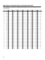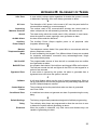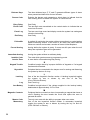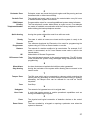
1
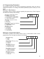
Penta
Installation, Operation
and Programming
Electronics Line (E.L.) Ltd.
www.elecline.com
ELECTRONICS LINE’S TECHNICAL SUPPORT DEPARTMENT
INTERNATIONAL: (972)-3-9211110
USA: 1-800-683-6835
ZI0094C (2/99)
2
TABLE OF CONTENTS
Introduction......................................................................................................... 4
About the Penta Installation, Operation and Programming Manual ..........................4
Publication Information .............................................................................................4
Chapter One: Overview ...................................................................................... 4
1.1: Specifications ....................................................................................................4
1.2: Zones ................................................................................................................5
1.3: Telephone Communication................................................................................5
1.4: Remote Programming.......................................................................................6
Chapter Two: Installation .................................................................................... 7
2.1: Parts and Options..............................................................................................7
2.2: Fuse Replacement ............................................................................................7
2.3: Wiring Diagram .................................................................................................8
2.4: Terminal Connections........................................................................................9
2.5: Mounting the Keypad.......................................................................................10
2.6: Turning on the System.....................................................................................11
Chapter Three: System Operation..................................................................... 12
3.1: General............................................................................................................12
3.2: Keypad Layout ................................................................................................12
3.4: Arming/Disarming............................................................................................13
3.6: Distress Keys...................................................................................................14
3.7: User Codes .....................................................................................................15
3.8: Zone Bypassing/Unbypassing .........................................................................16
3.9: Event Logs ......................................................................................................16
3.10: Additional Operations ....................................................................................17
Chapter Four: Programming ............................................................................. 18
4.1: General............................................................................................................18
4.2: Guide to Programming ....................................................................................18
4.3: Programming Parameters...............................................................................19
4.4: Periodic Test Timer Reset...............................................................................23
Appendix A: Hexadecimal Conversion Chart..................................................... 24
Appendix B: Glossary of Terms ........................................................................ 25
Index ................................................................................................................ 28
3
INTRODUCTION
About the Penta Installation, Operation and Programming Manual
This manual is designed to help you with the installation process for the Penta control
panel. We strongly urge you to read through this manual, in its entirety, before beginning
the installation process so that you can best understand all that this security system has
to offer your customers. This manual is not intended for end user use. End users are
encouraged to read the manual accompanying the system, the Penta User Manual. If you
have any questions concerning any of the procedures described in this manual please
contact Electronics Line at (972)-3-9211110 (International) or 1-800-683-6835 (USA).
Publication Information
Catalog Number: ZI0094C (2/99)
CHAPTER ONE: OVERVIEW
1.1: Specifications
Power Input
Power Output
Zones
Keypads
User Codes
Operating
Temperature
Dimensions
4
Secondary: 15-16.5Vac, 22-30VA transformer
Battery backup: 12Vdc/3.2Ah
Auxiliary power:
13.6 - 14.0V (AC operated)
12.0V Nominal (Battery operated)
Bell/siren output:
13.6 - 14.0V (AC operated)
12.0V Nominal (Battery operated)
600mA available for peripheral devices.
The bell/siren output must be supervised by a 2.2K ¼W resistor.
4 security zones supervised by 2.2K ¼W end of line resistors.
1 tamper/ ON/OFF keyswitch zone
Up to 3 individually addressed.
Current draw - 100mA max. for each keypad, 200mA max. if
three keypads are installed.
3 user initiated distress keys
6 (1 master code, 3 standard user codes, 1 duress code and
1 installer code.
Number of digits per user code – 4
0° to 50°C
260 x 237 x 83mm
1.2: Zones
The Penta control panel includes four security zones plus one tamper zone which can be
defined for use with an ON/OFF keyswitch. The four security zones are fully programmable and supervised by end of line resistors. The Penta offers five zone response
types for customized programming to suit a wide range of installations. Each zone can be
programmed to activate a siren/bell when tripped or to generate a silent alarm where only
a message is sent to the central station. The following is a summary of the operational
characteristics for each zone response type:
Perimeter Zone
Perimeter zones instantly generate an alarm when opened.
Suggested Use: Magnetic contacts or detectors protecting the doors and windows which
are never used to enter the premises.
Perimeter Zone With Delay
This zone type starts the entry delay when opened, allowing the user time to disarm the
system.
Suggested Use: Magnetic contacts or detectors protecting the doors commonly used to
enter or leave the premises.
Conditional Zone
If a perimeter zone with delay is opened first, conditional zones do not generate an alarm
when opened during the entry delay. If a conditional zone is opened first, an alarm is
generated instantly.
Suggested Use: Detectors protecting the area in which a keypad has been installed or the
area crossed in order to reach the keypad.
Interior Zone
Interior zones are automatically bypassed when the system is armed using the ‘Stay’
command Q, 9.
Suggested Use: Detectors protecting the interior areas in which the user requires
unrestricted movement when ‘Stay’ arming. For example bedrooms, bathrooms and
interior offices.
24hr Zone
24hr zones always generate an alarm when opened whether the system is armed or
disarmed.
Suggested Use: Panic buttons, glassbreak detectors and areas which require 24 hour
protection.
1.3: Telephone Communication
The Penta allows for up to two telephone numbers (primary and backup) to be
programmed into the system dedicated to central station communications or for use with
the ‘Follow-me’ format. An additional number can be programmed for use in conjunction
with the RP callback feature. Up to 16 digits can be programmed for each telephone
number. The Penta offers a number of communication options and supports either pulse
or DTMF dialing. If after five attempts the panel does not succeed to communicate, the
panel dials the backup telephone number. If communication is unsuccessful, the panel
will attempt to communicate every half hour until communication is established.
5
Central Station Communication
The Penta uses a standard 20pps 4/2 no parity protocol for central station
communication. All events can be programmed to transmit a two digit event code
message to the central station. These codes are usually assigned by the central station consult the central station operator for a listing of the different event codes.
Follow-me
The ‘Follow-me’ feature informs the user that an event has occurred by dialing the user’s
telephone number and sounding two beeps. After hearing the two beeps, pressing 3, 6, 9
or # on the phone sounds a number of tones to indicate exactly which type of alarm has
occurred. The number of tones indicates the type of alarm generated.
= Alarm from zone 1
= F key alarm
1 tone
1 long
= Alarm from zone 2
2 tones
tone
= Alarm from zone 3
= E or P key alarms, zone
3 tones
2 long
= Alarm from zone 4
or keypad tamper
4 tones
tones
After the alarm tones have been sounded, pressing 3, 6, 9 or # on the phone either
causes the panel to hang up or, if additional alarms have occurred, sound another set of
alarm tones. Note: Electronics Line recommends using a telephone unit with
Continuous DTMF mode. If only Burst mode is available it may be necessary to
press more than once. If using the Follow-me feature, program the relevant event
codes (addresses 11 – 18) with any value greater than 00.
1.4: Remote Programming
Electronics Line’s remote programming software enables programming and operation
from a PC. The software provides a comprehensive interface to the Penta control panel,
facilitating and cutting down the time taken in programming the system. RP access is
gained using a four digit code programmed at address 57. Without this code all remote
programming and operation is restricted.
Answering Machine Override
Answering machine override enables the control panel to distinguish between regular
incoming calls and a communication attempt by the RP (remote programmer) software.
An RP call is identified by the control panel as a sequence of two calls within a 30-second
time window.
1. The control panel does not answer the first incoming call.
2. The control panel opens a 30-second time window from the moment the telephone
stops ringing.
3. The control panel answers after 1 ring and RP communication is established.
This method enables the panel to share the same telephone line with answering
machines and fax machines.
RP Callback
RP call back is a toll-saver feature that makes remote programming more cost-effective.
When the remote programmer contacts the panel, the panel hangs up and calls the
telephone number programmed at address 56.
6
CHAPTER TWO: INSTALLATION
2.1: Parts and Options
Penta Household Burglary Alarm Control Panel
LED Keypad
2.2KΩ ¼W resistors
6 x ¼ mounting screws
Mounting studs
PCB support
Installation, Operation, and Programming Manual
User Manual
1
1
5
4
4
1
1
1
Optional Parts List
Additional Penta LED Keypad
‘Remote Programmer’ Up/Downloading Software
12Vdc Adapter for Remote Programmer
2.2: Fuse Replacement
The layout of the three protection fuses is as follows
F1: The Battery protection fuse protects the battery
charger circuit. To replace this fuse use a 1.6A/250V
fuse.
F2: The AC protection fuse protects terminals 1 and 2.
To replace this fuse use a 1.6A/250V fuse.
F3: The AUX protection fuse protects the auxiliary power
output to the keypad (terminals 3 and 4). To replace
this fuse use a 1.0A/250V fuse.
F1
F2
F3
F4
F4: The Bell Power protection fuse protects the active
bell output (terminals 7 and 8). To replace this fuse
use a 1.0A/250V fuse.
7
2.3: Wiring Diagram
+
-
R
E
D
B
L
A
C
K
Electronics Line (E.L.) Ltd. - Penta
12V/3.2Ah BATTERY:
Replace the battery every
3 - 5 years.
The maximum charging
current is 350mA.
Household Burglary Alarm Panel
JPD Jumper
for factory
default restore
Electronics Line (E.L.) recommends testing the system at least
once a week. Refer to the testing procedure found in the user
manual.
PROTECTION FUSES:
F1 (BATT): 1.6A/250V
F2 (AC): 1.6A/250V
F3 (AUX): 1.0A/250V
F4 (Bell): 1.0A/250V
F1
F2
F3
1
AC Transformer
50/60Hz
15-16.5Vac
22-30VA
Do not connect to
a switch controlled
receptacle.
LED Keypad
F4
2
3
AUX OUTPUT CURRENT DRAW:
The auxiliary output current allowed for peripheral units must
not exceed 300mA when one keypad is installed. For each
additional keypad (up to 3 max.) the permitted current draw
is reduced by 50mA.
BELL/SIREN OUTPUT:
600mA available for
security applications.
AUXILIARY POWER OUTPUT:
AC Operated: 13.6 - 14.0V
Battery Operated: 12V Nominal
4
AUX
+ -
5
6
KPD
K2 K1
7
8
+
-
9
10
11
12
13
14
15
16
Z1
17
18
19
20
Optional
Earth
Connection
Tamper
Zone
PGM
Label Part Number:
ML0024C (2/99)
Z2 Z3
Z4
ZONE
CONNECTIONS
Typical End
of Line
Resistor
N.C.
N.C.
Zone
Connections
2.2K 2.2K
(EOLR)
1
/4 W 1/4W
Telephone Line
Connections
OBSERVE PROPER
WIRING CONNECTIONS
(Refer to the Installation and
Operation Manual for
further information)
2.4: Terminal Connections
15-16.5Vac Input
Terminals 1 & 2: Connect a 15-16.5Vac transformer rated at 22-30VA, using 18 AWG
wire.
Auxiliary Power Output
Terminals 3(+), 4(-): The auxiliary power output connections supply power to keypads
and peripheral units such as detectors and other powered sensors.
Keypad Data Bus Connections
Terminals 5 & 6: Connect up to three individually addressed LED keypads to terminals
5 (K2), and 6 (K1). Make sure that the wires are connected to the same connections on
the keypad, see 2.5: Mounting the Keypad.
Bell Power Output
Terminals 7(+), 8(-): Connect these terminals to supply power to the bell. The bell
power output supplies AUX power, rated at 600mA max.
PGM Programmable Output
Terminal 9: The PGM output switches to
ground when activated, enabling the
connection of additional system status
indicators. Connect the PGM output as
shown in the diagram.
AUX
PGM
+
3
4
5
6
7
8
9
LOAD
(100mA max.)
Tamper Zone/Keyswitch Connections
Terminal 10: Connect a tamper switch or ON/OFF keyswitch to terminals 10(+) and 12(-).
Note: If neither the tamper zone nor keyswitch are used, short terminal 10 to 12 and
define this zone as Tamper Zone at Address 01.
Zone Connections
Terminals 11, 12, 13, 14, 15 & 16:
ZONE 1: Terminals 11(+) & 12(-)
ZONE 3: Terminals 14(+) & 15(-)
ZONE 2: Terminals 13(+) & 12(-)
ZONE 4: Terminals 16(+) & 15(-)
Telephone Line
Terminals 17, 18, 19, 20: The telephone line should be connected (using the
standard Telco wires - minimum 26 AWG) as follows: 17 - Home Tip, 18 - Home Ring,
19 - Telco Tip, and 20 - Telco Ring.
9
2.5: Mounting the Keypad
Configuration
Jumpers
Buzzer
Terminal
Block
Tamper
Switch
Up to 3 LED keypads can be connected to the Penta control panel. To mount the
keypad:
1. Separate the front and back cover of the keypad by pressing the locking tabs,
situated at the bottom of the keypad, with a small flathead screwdriver.
2. Pull the keypad wires through the opening in the back cover nearest the terminal
block and mount the back cover to the wall.
3. Define the keypad address by configuring jumpers A & B according to the following
diagram.
Jumper
Removed
Jumper
Installed
A
B
Keypad 1
10
A
B
Keypad 2
A
B
Keypad 3
4. Connect the keypad to the control panel according to the following diagram.
+
3
K2
K1
5
6
4
CONTROL PANEL
KEYPAD
K1
K2
+
5. Reassemble the front and back cover of the keypad.
2.6: Turning on the System
Once all of the systems components are properly connected to their destination
terminals, the Penta is ready to be turned on. To avoid the risk of electrical shock or
damage to the control panel, make sure that both the AC supply and the battery are
connected properly before plugging in the system. If you experience any difficulties in
applying power to the unit, please contact Electronics Line’s Technical Support
Department. The Penta control panel is supplied with a default program that includes
typical programming data which means that minimum programming is required for
typical installations.
To turn on the system:
1. Install the JPD jumper located at the top of the board.
2. Reapply power and wait for 10 seconds; the keypad beeps to indicate the end of the
10 second period.
3. Disconnect both the AC and battery power supply.
4. Remove the JPD jumper.
5. Reapply power; the default program is restored.
The default settings can be reset at any time by disconnnecting the power supply and
repeating the above procedure.
11
CHAPTER THREE: SYSTEM OPERATION
3.1: General
All operation and programming of the Penta can be performed using any one of the
three LED keypads that can be installed with each system. This section offers a
complete explanation of the keypad functions and of the LED display, incorporating a
summary of command codes used in system operation.
3.2: Keypad Layout
READY
1
Zone
Indicators
2
3
Status
Indicators
4
SYSTEM
ARMED POWER
Status
Indicators
F
Numeric
Keypad
E
Distress Keys
P
Buzzer
The numeric keypad is used for operation and programming of the system.
Additionally, three distress keys enable the user to send one of three individual distress
signals to the central station - see 3.6: Distress Keys for further information.
LED Display
1 - 4: LEDs 1 - 4 are used to display zone status. The corresponding LED lights up if a
zone is open. If a zone is bypassed the corresponding LED blinks.
READY: The Ready LED lights up to indicate that there are no open zones or tamper
conditions and the system is ready to be armed.
SYSTEM: The System LED blinks to indicate that new events have been recorded in
one of the logs and when displaying additional system information such as
programming mode or bypass mode.
ARMED: The Armed LED lights up to indicate that the system is armed or in
programming mode.
POWER: The Power LED lights up when both AC & battery power are OK, blinks when
the battery is low & AC power is OK, and goes out in the event of AC failure.
12
3.3: Command Codes
Commands are executed by pressing the ‘Q‘ button followed by the corresponding
command number and, in some cases, a valid user code. The following is a summary
of the command codes used in system operation.
Q0
Quick Arm
Q5 + (User Code 1)
Program User Codes
Q1 + (User Code)
Bypass Mode
Q6
Zone Chime
Q2
Emergency/Trouble
Event Log
Q7 + (Installer Code)
Programming Mode
Q3
Zone Alarm
Event Log
Q8 + (User Code)
Forced Arming
Q4
Bell/LED Test
Q9 + (User Code)
Stay Arming
3.4: Arming/Disarming
The following section explains the various arming and disarming methods.
Arming
When all zones are secured the system can be armed normally. Arming the system
transmits a message to the central station identifying which user performed the
operation.
To arm the system:
1. Check that all zones are closed; the Ready LED lights up to indicate that the
system is ready to be armed.
2. Enter a valid user code; the keypad beeps until the end of the exit delay.
Forced Arming
Forced arming enables the user to arm the system with open zones. Electronics Line
recommends waiting until all of the zones are secured and the system can be armed
normally. Note: If zones are still not secured after the exit delay has ended, an
alarm will be generated.
To force arm the system:
1. Press Q, 8.
2. Enter a valid user code; the keypad beeps until the end of the exit delay.
Quick Arming
This feature allows the Penta to be armed without a valid user code. Quick arming the
system transmits an “Armed by User 1” message to the central station.
To “Quick” arm the system:
1. Check that all zones are closed; the Ready LED lights up to indicate that the
system is ready to be armed.
2. Press Q, 0; the keypad beeps until the end of the exit delay.
13
Stay Arming
This feature only arms perimeter zones. This allows the user to stay within the
protected area while the system is armed.
To “Stay” arm the system:
1. Check that all zones are closed apart from the interior zones; the Ready LED lights
up to indicate that the system is ready to be armed.
2. Press Q, 9.
3. Enter a valid user code; the keypad beeps until the end of the exit delay.
Immediate Arming
The system can be operated without an entry/exit delay. Pressing Q during the exit
delay or when the system is armed cancels both the exit and entry delay times.
Disarming
The Penta can be disarmed by entering a valid user code during the entry delay. If an
error is made entering the code, press ‘#’ and enter the code again. When the code is
accepted the Armed LED and the pulsed delay tone are turned off. If the correct code is
not entered by the end of the delay time, an alarm will be generated.
Keyswitch Arming/Disarming
The system can be armed and disarmed using an ON/OFF keyswitch. The keyswitch
has two operation modes.
1. Latching - closing the keyswitch arms the system, opening disarms the system.
2. Momentary - opening and closing the keyswitch either arms or disarms the system.
3.6: Distress Keys
In the case of an emergency, 3 types of alarms can be generated by pressing and
holding down the desired distress key for more than 2 seconds. These alarms will send
the relevant distress codes to the central station. The distress keys are as follows:
14
F
FIRE: Sounds the fire bell, sends the ‘Fire’ event code to the central
station (address 17) and registers in the Emergency/Trouble event log.
E
EMERGENCY: Sends the ‘Emergency’ event code to the central station
(address 18), sounds the siren (if programmed at address 01) and
registers in the Emergency/Trouble event log.
P
POLICE: Sends the ‘Police’ event code to the central station (address 16),
sounds the siren (if programmed at address 01) and registers in
the Emergency/Trouble event log.
3.7: User Codes
The Penta is capable of maintaining four user codes, a duress code and an installer
code. Each of these codes are four digits long. Of the four user codes, only User
Code 1 (default 1111) has authorization to modify other user codes and the duress
code. The installer’s code (default 1234) is the only user code which grants access to
the programming parameters and is programmable at address 61.
To program user codes 1-4:
1. Press Q, 5.
2. Enter User Code 1; the Armed and System LEDs flash and the zone LEDs indicate
the programming status of each user code as follows:
OFF:
ON:
FLASHING:
NOT PROGRAMMED
PROGRAMMED
CURRENTLY BEING PROGRAMMED
3. Enter the number of the code to be changed (1-4); the requested zone LED flashes.
4. Enter the new user code; the LED stops flashing.
5. Enter the next code to be changed or press # to exit.
Note: If the new code is identical to an existing user code, an error tone will be
sounded and the new code will not be accepted.
To erase a user code:
1. Press Q, 5.
2. Enter User Code 1.
3. Enter the number of the code to be erased (1-4); the requested zone LED flashes.
4. Enter Q, Q, Q, Q; the LED stops flashing and the code is erased.
5. Enter the next code to be erased or press # to exit.
Note: Do not erase User Code 1! Erasing this code denies the user the ability to
program user codes. If User Code 1 is accidentally erased, reset the default
program as described in 2.6: Turning on the System.
Duress Code
In the event that the user is forced to disarm the system and/or cancel the bell, entering
the duress code will send a silent alarm to the central station.
To program the duress code:
1. Press Q, 5.
2. Enter User Code 1.
3. Press 5; the Ready LED flashes.
4. Enter a new duress code or Q, Q, Q, Q to erase the existing code.
5. Press # to exit.
15
3.8: Zone Bypassing/Unbypassing
The Penta offers the user the ability to bypass zones. When a zone is bypassed, it is
ignored by the system and will not generate an alarm when tripped.
To bypass a zone:
1. Press Q, 1.
2. Enter a valid user code; the System LED flashes and the LEDs of any currently
bypassed zones light up.
3. Enter the number of the zone to be bypassed; the corresponding zone LED lights up.
4. Press # to exit bypass mode; the bypassed zones flash.
To unbypass a zone:
1. Press Q, 1.
2. Enter a valid user code; the System LED flashes and the LEDs of any currently
bypassed zones light up.
3. Enter the number of the zone to be unbypassed; the corresponding zone LED turns off.
4. Press # to exit bypass mode.
Note: Disarming the system automatically unbypasses all bypassed zones.
3.9: Event Logs
The event logs record events that the system has undergone since the last arming. If
any events have been recorded in either event log, the System LED flashes until the
relevant event log has been viewed. In the event that a trouble condition still exists, the
System LED continues to flash until the condition has been remedied.
Emergency/Trouble Event Log
Zone tamper, keypad trouble or any of the three distress key alarms are registered in
the Emergency/Trouble event log.
To view the Emergency/Trouble event log:
1. Press Q, 2; the various trouble conditions are indicated by the zone LEDs.
The following is a summary of the trouble condition that each LED indicates when lit:
1 - Tamper or Keypad Trouble
2 - Alarm from P key
3 - Alarm from F key
4 - Alarm from E key
2. Press # to exit the event log.
Note: The event logs can only be viewed when the system is disarmed.
Zone Alarm Event Log
The Zone Alarm event log displays the zones from which an alarm was generated since
the system was last armed.
To view the Zone Alarm event log:
1. Press Q, 3; an alarm from a specific zone is indicated by the corresponding zone
LED.
2. Press # to exit the event log.
Both logs are automatically reset when the system is next armed.
16
3.10: Additional Operations
Bell Cancel
To cancel the bell:
•
Enter a valid user code or turn the keyswitch as if disarming the system.
Bell/LED Test
To perform a bell/LED test:
•
Press Q, 4; the siren is sounded and all LEDs on the keypad are lit for a period of
two seconds.
Zone Chime On/Off
The keypad can be set to chime when Perimeter With Delay or Perimeter zones are
opened or closed. This feature only functions when the system is disarmed.
To toggle the zone chime On or Off:
•
Press Q, 6 while the system is disarmed.
The keypad will sound a continuous tone to indicate “Zone Chime ON” or a series of
short beeps to indicate “ Zone Chime OFF”.
Keypad Backlight On/Off
To toggle the backlight of any keypad On or Off:
•
Press and hold down # for more than 2 seconds.
17
CHAPTER FOUR: PROGRAMMING
4.1: General
The Penta control panel may be programmed using either the LED keypad or
Electronics Line’s Remote Programmer. If using the Remote Programmer, refer to the
instructions provided with the software.
4.2: Guide to Programming
The control panel has 61 parameter addresses allowing precise custom configuration of
the system to suit the user’s needs. The options for each address are listed in section
4.3: Programming Parameters. All of the programming parameters are stored in the
Penta’s non-volatile EEPROM memory which stores the data in the event that power is
disconnected. Before programming directly after installing the system, restore the
default parameters as explained in 2.6: Turning on the System.
To program the system:
1. Make sure the system is disarmed.
2. Press Q, 7.
3. Enter the Installer Code (the default installer code is 1234); the Armed LED lights
up and the System LED flashes.
4. Enter the two-digit parameter number to be programmed; the Ready LED lights up
and the Armed LED turns off.
5. Enter a new value or press # to cancel; if the value has been successfully changed,
the keypad sounds an acknowledge tone to confirm and the Ready LED turns off.
6. Press # to exit programming mode.
Note: The default Installer Code should be changed immediately after installing
the system.
Hexadecimal Data
Some of the programming parameters require a hexadecimal value to be entered. To
enter hexadecimal data, use the following combination of digits for hexadecimal
numbers greater than 9.
Q, 0 = A
Q, 1 = B
Q, 2 = C
Q, 3 = D
Q, 4 = E
Q, 5 = F
Keypad Programming Tones
The keypad sounds a series of tones to aid programming. These tones offer the
installer status indication during programming. The following is a summary of the
keypad programming tones.
Short Beep
Long Beep
Low Beeps
Continuous Beeps
18
=
=
=
=
Confirmation of each keystroke
Acknowledgment of a successful entry
Error, illegal entry
Entry/Exit delay
4.3: Programming Parameters
The following section lists the Penta’s programming parameters which are used to
configure the system. For a listing of the default parameters please contact your local
dealer.
Address 01: Miscellaneous
This address offers a number of options regarding the system set-up. Enter 5 digits at
this address according to the following:
First Digit: P and E Key Function
0 - P and E Audible Alarms
1 - E Audible Alarm, P Silent Alarm
2 - E Silent Alarm, P Audible Alarm
3 - P and E Silent Alarms
0
Third Digit: Keyswitch Function
0 - Latching
8 - Momentary
Fourth Digit: Tamper Zone Definition
0 – Arm/Disarm Keyswitch
4 - Tamper Zone
Fifth Digit: Keypads
0 - No Keypads
1 - One Keypad
2 - Two Keypads
3 - Three Keypads
Address 02: Communication Options
This address consists of the various options used in communication and/or remote
programming. Enter five digits according to the following.
First Digit: Dialing
0 - Pulse
1 - DTMF
Second Digit: RP Access Type
0 - Passcode
8 - Callback
Third Digit: RP Access
0 - Disable RP Access
4 - Enable RP Access
Fourth Digit: Handshake
0 - 1400Hz Handshake
2 - 2300Hz Handshake
Fifth Digit: Protocol
0 - 20pps 4/2 No Parity
1 - Follow Me
19
Address 03: Zone 1 Definition
One of five response types can be assigned to zone 1. Each zone type can be
programmed as ‘Silent’ or ‘Audible’. A ‘Silent’ zone will not activate a siren or bell when
the zone is tripped.
00 - Perimeter zone with delay (Silent)
10 - Perimeter zone with delay (Audible)
01 - Perimeter zone (Silent)
11 - Perimeter zone (Audible)
02 - Conditional zone (Silent)
12 - Conditional zone(Audible)
03 - Interior zone (Silent)
13 - Interior zone (Audible)
04 - 24hr zone (Silent)
14 - 24hr zone (Audible)
Address 04: Zone 2 Definition
Same as above for zone 2.
Address 05: Zone 3 Definition
Same as above for zone 3.
Address 06: Zone 4 Definition
Same as above for zone 4.
Address 07: Entry Delay Time
The entry delay timer determines the amount of time the user has to disarm the system
before an alarm is activated. The entry delay is only initiated if the premises are entered
through a zone defined as ‘perimeter with delay’. Enter a hexadecimal value between 1 and
255 seconds at this address using the hexadecimal conversion chart in Appendix A.
Address 08: Exit Delay Time
The amount of time the user has to leave the premises after arming is determined by
the exit delay timer. An open zone will not activate an alarm during this period. Enter a
hexadecimal value between 1 and 255 seconds at this address using the hexadecimal
conversion chart in Appendix A.
Address 09: Bell Cut-Off Time
The bell cut-off is the period of time that the bell or siren will be activated after an alarm
has occurred. Enter a value between 1 and 5 minutes at this address.
20
Address 10: PGM Options
The PGM (Programmable Output) can be used for indication of certain status or trouble
conditions. When the PGM output is activated terminal 9 switches to ground. Choose
the PGM output setting from the following table.
Value
00
01
02
04
08
10
Type
PGM Disabled
System Status
System Status
System Status
System Trouble
System Status
Activated By
--System Armed
Entry/Exit Tone Follower
System in Communication
AC Loss
Bell Follower
Deactivated By
--System Disarmed
Entry/Exit Tone Follower
End of Communication
AC Restore
Bell Follower
Event Codes
All events can be programmed to transmit a two digit event code message to the
central station. These codes are usually assigned by the central station - consult the
central station operator/owner for a listing of the different event codes. To disable an
event code program the code as 00. To disable communications program all event
codes as 00.
Address 11: Alarm from Zone 1*
Address 12: Alarm from Zone 2*
Address 13: Alarm from Zone 3*
Address 14: Alarm from Zone 4*
Address 15: Alarm from Tamper Zone*
Address 16: [P] Key alarm*
Address 17: [F] Key alarm*
Address 18: [E] Key alarm*
Address 19: Zone 1 Restore
Address 20: Zone 2 Restore
Address 21: Zone 3 Restore
Address 22: Zone 4 Restore
Address 23: Tamper Zone Restore
Address 24: [P] Key alarm restore
Address 25: [F] Key alarm restore
*
When using the Follow-me feature, program these addresses with a value greater than 00.
21
Address 26: [E] Key alarm restore
Address 27: System Armed (User Code 1)
Address 28: System Armed (User Code 2)
Address 29: System Armed (User Code 3)
Address 30: System Armed (User Code 4)
Address 31: System Disarmed (User Code 1)
Address 32: System Disarmed (User Code 2)
Address 33: System Disarmed (User Code 3)
Address 34: System Disarmed (User Code 4)
Address 35: System Disarmed (Duress Code)
Address 36: Low Battery
Address 37: AC Loss
Address 38: Not In Use
Address 39: Keypad Trouble
Address 40: Low Battery Restore
Address 41: AC Loss Restore
Address 42: Not In Use
Address 43: Keypad Trouble Restore
Address 44: Bell Cancel
Address 45: Periodic test
Address 46: Bypass Zone 1
Address 47: Bypass Zone 2
Address 48: Bypass Zone 3
Address 49: Bypass Zone 4
Address 50: Unbypass Zone 1
Address 51: Unbypass Zone 2
Address 52: Unbypass Zone 3
Address 53: Unbypass Zone 4
22
Telephone numbers
Address 54: Primary Telephone Number
The primary telephone number is the first number that is dialed when an event occurs.
A maximum of 16 digits can be entered at this address. To add a two-second pause,
enter B (Q, 1). To switch from pulse to DTMF dialing enter E (Q, 4). These hexadecimal
digits, B and E, are included in the 16 digit total. Press ENTER after the last digit of the
telephone number has been programmed.
Address 55: Backup Telephone Number
The backup telephone number is dialed if the panel fails to communicate with the
primary number after five attempts. The backup telephone number is programmed in
the same way as the primary telephone number (address 54).
Address 56: RP Callback Telephone Number
Remote programming communication can be established using two methods,
passcode and callback (see address 02, second digit). If RP callback is selected the
panel receives a call from the remote programmer, hangs up and calls back using the
telephone number programmed at this address. The RP callback telephone number is
programmed in the same way as the primary telephone number (address 54).
Note: To disable a telephone number, enter the appropriate address and press
ENTER. It is not possible to program a backup number unless a primary number
has been programmed.
Address 57: RP Access Code
This 4-digit code grants access to the remote programmer. Note: Do not enter Hex digits.
Address 58: Account Number
When an event code is sent, the central station receives an account number to identify
the customer. Enter a 4-digit account number at this address.
Address 59: Installer Code
The installer code is a 4-digit code which grants access to programming mode. The
default for this code (1234) should be changed immediately after installing the system.
Note: Do not enter Hex digits.
4.4: Periodic Test Timer Reset
The periodic test event code (address 45) is sent to the central station once every 24
hours. The first transmission of this code is sent 24 hours after power is applied to the
control panel. If a different time is required, control panel can be programmed to send
the event code every 24 hours from the moment the periodic test timer is reset.
To reset the periodic test timer:
1. Press Q, 7 to enter programming mode.
2. Enter the Installer Code; the Armed LED lights up and the System LED flashes.
3. Enter 99; the periodic test timer is reset and the periodic test code is sent to the
central station.
4. Press # to exit programming mode.
23
APPENDIX A: HEXADECIMAL CONVERSION CHART
The following is a decimal to hexadecimal conversion chart to be used as an aid in
programming:
Dec
Hex
Dec
Hex
Dec
Hex
Dec
Hex
Dec
Hex
Dec
Hex
Dec
Hex
Dec
Hex
00
00
32
20
64
40
96
60
128
80
160
A0
192
C0
224
E0
01
01
33
21
65
41
97
61
129
81
161
A1
193
C1
225
E1
02
02
34
22
66
42
98
62
130
82
162
A2
194
C2
226
E2
03
03
35
23
67
43
99
63
131
83
163
A3
195
C3
227
E3
04
04
36
24
68
44
100
64
132
84
164
A4
196
C4
228
E4
05
05
37
25
69
45
101
65
133
85
165
A5
197
C5
229
E5
06
06
38
26
70
46
102
66
134
86
166
A6
198
C6
230
E6
07
07
39
27
71
47
103
67
135
87
167
A7
199
C7
231
E7
08
08
40
28
72
48
104
68
136
88
168
A8
200
C8
232
E8
09
09
41
29
73
49
105
69
137
89
169
A9
201
C9
233
E9
10
0A
42
2A
74
4A
106
6A
138
8A
170
AA
202
CA
234
EA
11
0B
43
2B
75
4B
107
6B
139
8B
171
AB
203
CB
235
EB
12
0C
44
2C
76
4C
108
6C
140
8C
172
AC
204
CC
236
EC
13
0D
45
2D
77
4D
109
6D
141
8D
173
AD
205
CD
237
ED
14
0E
46
2E
78
4E
110
6E
142
8E
174
AE
206
CE
238
EE
15
0F
47
2F
79
4F
111
6F
143
8F
175
AF
207
CF
239
EF
16
10
48
30
80
50
112
70
144
90
176
B0
208
D0
240
F0
17
11
49
31
81
51
113
71
145
91
177
B1
209
D1
241
F1
18
12
50
32
82
52
114
72
146
92
178
B2
210
D2
242
F2
19
13
51
33
83
53
115
73
147
93
179
B3
211
D3
243
F3
20
14
52
34
84
54
116
74
148
94
180
B4
212
D4
244
F4
21
15
53
35
85
55
117
75
149
95
181
B5
213
D5
245
F5
22
16
54
36
86
56
118
76
150
96
182
B6
214
D6
246
F6
23
17
55
37
87
57
119
77
151
97
183
B7
215
D7
247
F7
24
18
56
38
88
58
120
78
152
98
184
B8
216
D8
248
F8
25
19
57
39
89
59
121
79
153
99
185
B9
217
D9
249
F9
26
1A
58
3A
90
5A
122
7A
154
9A
186
BA
218
DA
250
FA
27
1B
59
3B
91
5B
123
7B
155
9B
187
BB
219
DB
251
FB
28
1C
60
3C
92
5C
124
7C
156
9C
188
BC
220
DC
252
FC
29
1D
61
3D
93
5D
125
7D
157
9D
189
BD
221
DD
253
FD
30
1E
62
3E
94
5E
126
7E
158
9E
190
BE
222
DE
254
FE
31
1F
63
3F
95
5F
127
7F
159
9F
191
BF
223
DF
255
FF
24
APPENDIX B: GLOSSARY OF TERMS
24hr Zone
A zone which is always active regardless of whether the system is armed
or disarmed. Opening a 24hr zone always generates an alarm.
A
AC Loss
The disruption of AC power. In the event of AC loss, the panel waits five
minutes before sending an event message.0
Answering
Machine Override
The method used in RP communication allowing the control panel to
share a telephone line with answering machines, fax machines etc.
Armed
The state during which the control panel is fully activated. In most cases,
when the system is armed, opening a zone generates an alarm.
Audible Alarm
An alarm that sounds the bell/siren.
Auxiliary
Power Output
The Auxiliary Power Output supplies power to all peripheral units
(keypads, detectors etc.)
Backup
Telephone Number
The telephone number dialed if the panel fails to communicate with the
primary telephone number.
Beep
A tone sounded by the keypad. Four different kinds of beep are sounded
for keystroke confirmation, successful entry acknowledge-ment, illegal
entry and exit/entry delay.
Bell Cut-Off
The programmable amount of time the bell is sounded when an audible
zone generates an alarm.
Bell/LED Test
An operation that checks if the bell/siren and keypad LEDs are functional.
The bell test sounds the bell and lights all the LEDs on the keypad for a
period of two seconds.
Bypassed Zone
A zone which is ignored by the system. No alarm is generated from a
bypassed zone even when the system is armed.
B
C
Callback
Central Station
Chime
Conditional Zone
A toll saver feature which cuts the cost of remote programming. When a
call is received from the remote programmer the panel hangs up and calls
the RP Callback telephone number.
The monitoring service the panel alerts when an alarm is generated.
see Zone Chime
A conditional zone does not generate an alarm if opened during the entry
delay.
D
Default Settings
The factory programmed parameters designed to facilitate programming.
Delay
The exit/entry delay times are programmed to allow the user time to arm
or disarm the system without generating an alarm.
Disarmed
When the system is disarmed, only 24hr zones and distress keys are
capable of generating an alarm.
25
Distress Keys
The three distress keys (F, E and P) generate different types of alarm
when pressed and held down for two seconds.
Duress Code
Entering the duress code generates a silent alarm to indicate that the
user is being forced to disarm the system or cancel the bell.
E
Entry Delay
See Delay
Event Code
The two-digit code transmitted to the central station to indicate that an
event has occurred.
Event Log
The two event logs record and display events the system has undergone
since the last arming.
Exit Delay
See Delay
F
Follow-Me
A method of monitoring the system without connecting to a central station
based monitoring service. In the event of an alarm, the panel dials the
follow-me number and sounds a number of tones via the telephone.
Forced Arming
Arming before the system is ready. If zones are still open when the exit
delay has expired an alarm will be generated.
I
Immediate Arming
Installer Code
Interior Zone
Arming the system without an exit/entry delay.
The code which grants access to programming mode.
A zone that is not armed during Stay arming
K
Keypad Trouble
Condition brought about by improper definition of keypads or if a keypad
has been disconnected.
Keyswitch
Peripheral device connected to the tamper zone for arming and disarming
the system by the turn of a key.
Latching
One of the two keyswitch function modes. A latching keyswitch toggles
the system to arm or disarm by one turn of the key
(On or Off=Arm/Disarm).
L
Log
Low Battery
See Event Log
Condition brought about if the voltage supplied to the backup battery
deteriorates to approximately 10.5V or less.
M
Magnetic Contacts
Master Code
Momentary
26
Peripheral device mounted on doors incorporating a magnet that closes a
circuit. Opening the door breaks the circuit and opens the zone to
generate an alarm.
The only user code with the ability to program other user codes.
One of the two keyswitch function modes. A momentary keyswitch
toggles the system to arm or disarm by turning the key on and off.
(On & Off=Arm or Disarm).
P
Perimeter Zone
Perimeter zones are armed during both regular and Stay arming and can
be defined with or without an exit delay.
Periodic Test
The periodic test event code is sent to the central station every 24 hours
to indicate that the system is functional.
PGM Output
Primary
Telephone Number
Programmable output for connecting additional system status indicators.
The first telephone number dialed when an event occurs. Five attempts
are made to establish communication with the Primary telephone number
before dialimg the backup telephone number.
Q
Quick Arming
Arming the system without the need for a valid user code.
R
Ready
The state in which all zones are closed and the system is ready to be
armed.
Remote
Programmer
The software developed by Electronics Line used for programming the
system using a PC from a remote location or on-site.
Restore
The restoral of a trouble condition to its normal state. For example, if AC
power is reconnected, an AC Loss Restore event code is sent to the
central station.
RP
RP Access Code
Abbreviation of Remote Programmer
The code that grants access to the remote programmer. The RP Access
Code prevents the system being sabotaged using unauthorized remote
programming.
S
Silent Alarm
An alarm that does not activate the bell/siren when generated.
Stay Arming
Arming the perimeter of the system while allowing free movement in the
interior zones.
Tamper Zone
The fifth zone which can be connected to a tamper switch protecting the
control panel by generating an alarm when the metal housing is opened.
Alternately, the tamper zone can be defined for use with an On/Off
keyswitch.
T
Tone
See Beep
U
Unbypass
The restoral of a bypassed zone to its original state.
User Code
A code that grants access to certain operational capabilities such as
arming and disarming the system.
Zone
The physical and logical connection of detection devices to the control
panel.
Zone Chime
The tone sounded by a keypad on opening a perimeter zone when the
system is disarmed.
Z
27
INDEX
24hr zone ........................................20
24hr Zone ..........................................5
AC Protection Fuse............................7
Account Number ..............................23
Additional Operations ......................17
Answering Machine Override..............6
Armed LED......................................12
Arming.............................................13
Forced .....................................................13
Immediate ................................................14
Keyswitch ................................................14
Quick .......................................................13
Stay..........................................................14
Audible Zone ...................................20
Backlight..........................................17
Backup Telephone Number..........5, 23
Bell Cut-Off......................................20
Bell Test ..........................................17
Bell/Power Protection Fuse ................7
Bypassing
zones .......................................................16
Bypassing Zones .............................16
Callback ......................................6, 19
Central Station Communication .....5, 6
Account Number......................................23
Event Code ................................................6
Protocol......................................................6
Codes
user..........................................................15
Codes
Duress .....................................................15
Installer ....................................................15
Command Codes.............................13
Conditional Zone..........................5, 20
Connections.......................................9
Contents ............................................3
Default Program ..............................11
Delay
Entry ........................................................20
Exit...........................................................20
Dialing Options ................................19
Dimensions........................................4
Disarming ........................................13
Keyswitch ................................................14
Distress Keys...................................14
Duress Code....................................15
E Key......................................... 14, 19
28
EEPROM.........................................18
Emergency Key................................14
Entry Delay ......................................20
Entry/Exit Delay
Cancelling................................................ 14
Erasing User Codes .........................15
Event Codes ....................................21
Event Logs.......................................16
Exit Delay ........................................20
F Key...............................................14
Fire Key ...........................................14
Follow-me..........................................5
General Description................................... 6
Forced Arming .................................13
Fuse Replacement .............................7
Handshake ......................................19
Hexadecimal Data............................18
Conversion Chart..................................... 24
Immediate Arming ...........................14
Installation .........................................7
Installer Code ...................... 15, 18, 23
Interior Zone .......................... 5, 14, 20
Introduction........................................4
JPD Jumper.....................................11
Keypad
Address Definition ................................... 10
Backlight On/Off...................................... 17
Command Codes .................................... 13
Configuration ........................................... 19
Connections ............................................ 11
Display..................................................... 12
Functions................................................. 12
LED Indicators......................................... 12
Mounting.................................................. 10
Programming Tones................................ 18
Keypad Protection Fuse .....................7
Keyswitch ........................................19
Keyswitch Arming/Disarming ...........14
LED Display.....................................12
Miscellaneous Parameters ...............19
Mounting the Keypad ...................9, 10
ON/OFF Keyswitch ..........................14
Operating Temperature ......................4
Optional Parts....................................7
Options..............................................7
Overview ...........................................4
P Key.........................................14, 19
Parameter Addresses ......................18
Parameters
programming............................................19
Parts
List of.........................................................7
Optional .....................................................7
Perimeter Zone ...................... 5, 17, 20
Perimeter Zone With Delay ..........5, 20
Periodic Test Timer Reset................23
PGM................................................21
Police Key .......................................14
Power Input .......................................4
Power LED ......................................12
Power Output.....................................4
Programmable Output .....................21
Programming...................................18
Duress Code............................................15
Guide .......................................................18
Parameters ........................................18, 19
User Codes..............................................15
Protection Fuses................................7
Publication Information ......................4
Quick Arming...................................13
Ready LED ......................................12
Remote Programming..................6, 19
Access Code ...........................................23
Callback Number .....................................23
Reset
Default Settings .......................................11
Event Logs...............................................16
Periodic Test Timer .................................23
RP Access Code..............................23
RP Callback............................. 5, 6, 19
Telephone Number ..................................23
Silent Zone ......................................20
Status Indication ..............................21
Stay Arming.....................................14
System LED.....................................12
Tamper Zone ...................................19
Telephone Communication ................5
Event Codes............................................ 21
Follow-me .................................................. 6
RP Communication ................................... 6
Telephone Line
Connections .............................................. 9
Telephone Numbers.....................5, 23
Backup ...................................................... 5
Telephone Options...........................19
Terminal Connections ........................9
Test
Bell .......................................................... 17
Trouble Indication ............................21
Turning on the System .....................11
Unbypassing Zones .........................16
User Codes..................................4, 15
Erasing .................................................... 15
Programming........................................... 15
Wiring Diagram .................................8
Zone Chime .....................................17
Zones ................................................4
24hr ..................................................... 5, 20
Audible .................................................... 20
Bypassing................................................ 16
Conditional........................................... 5, 20
Connections .............................................. 9
Definition ................................................. 20
General Description................................... 5
Interior ........................................... 5, 14, 20
Perimeter....................................... 5, 17, 20
Perimeter with delay .................................. 5
Perimeter With Delay .............................. 20
Silent ....................................................... 20
Tamper................................................ 9, 19
Unbypassing ........................................... 16
29
ELECTRONICS LINE (E. L.) LTD. AND ITS SUBSIDIARIES - LIMITED WARRANTY
ELECTRONICS LINE (E. L.) LTD. AND ITS SUBSIDIARIES (EL) warrants its products to be free from
manufacturing defects in materials and workmanship for two years following the date of sale. EL will, within
said period, at its option, repair or replace any product failing to operate correctly without charge to the
original purchaser or user. In case of defect, contact the security professional who installed and maintains
your security system. In order to exercise the warranty, the product must be returned by the user or
purchaser, shipping costs prepaid and insured to EL. After repair or replacement, EL assumes the cost of
returning products under warranty. EL will not be responsible for any dismantling or reinstallation changes.
This warranty shall not apply to any equipment, or any part thereof, which has been repaired by others,
improperly installed, improperly used, abused, altered, damaged, subjected to acts of God, or on which any
serial numbers have been altered, defaced or removed.
There is no express or implied warranty of merchantability or warranty of fitness for a particular purpose. Any
action for breach of warranty, including but not limited to any implied warranty of merchantability, must be
brought within the six months following the end of the warranty period. In no case shall EL be liable to anyone
for any consequential or incidental damages for breach of this or any other warranty, express or implied, even
if the loss or damage is caused by the EL's own negligence or fault.
In no event shall EL be liable for an amount in excess of EL's original selling price of the product, for any loss
or damage, whether direct, indirect, incidental, consequential, or otherwise arising out of any failure of the
product. CONSEQUENTLY, EL SHALL HAVE NO LIABILITY FOR ANY PERSONAL INJURY, PROPERTY
DAMAGE, OR OTHER LOSS BASED ON A CLAIM THE PRODUCT FAILED TO GIVE WARNING. EL's
warranty, as hereinabove set forth, shall not be enlarged, diminished or affected by and no obligation or
liability shall arise or grow out of EL's rendering of technical advice or service in connection with Buyers order
of the goods furnished hereunder.
This warranty contains the entire warranty. Additionally, this warranty is in lieu of all other
obligations or liabilities on the part of EL. It is the sole warranty and any prior agreements or
representations, whether oral or written, are either merged herein or are expressly canceled. EL
neither assumes, nor authorizes any other person purporting to act on its behalf to modify, to
change, or to assume for it, any other warranty or liability concerning its products.
EL RECOMMENDS THAT THE ENTIRE SYSTEM BE COMPLETELY TESTED WEEKLY.
Warning: Despite frequent testing, and due to, but not limited to, any or all of the following: criminal
tampering, electrical or communications disruption, it is possible for the system to fail to perform as expected.
EL does not represent that the product/system may not be compromised or circumvented; or that the product
or system will prevent any personal injury or property loss by burglary, robbery, fire or otherwise; nor that the
product or system will in all cases provide adequate warning or protection. A properly installed and
maintained alarm may only reduce risk of burglary, robbery, fire or otherwise but it is not insurance or a
guarantee that these events will not occur. Therefore, the installer should in turn advise the consumer to take
any and all precautions for his or her safety including, but not limited to, fleeing the premises and calling
police or fire department, in order to mitigate the possibilities of harm and/or damage.
EL is not an insurer of either the property or safety of the user's family or employees, and limits its liability for
any loss or damage including incidental or consequential damages to EL’s original selling price of the product
regardless of the cause of such loss or damage. If the user wishes to protect itself to a greater extent, EL will,
at user's sole cost and expense, obtain an insurance policy to protect the user, supplemental to user's own
policy, at a premium to be determined by EL's insurer upon written notice from user by Certified Mail, Return
Receipt Requested, to EL's home office address, and upon payment of the annual premium cost by user.
Some states do not allow limitations on how long an implied warranty lasts or do not allow the exclusion or
limitation of incidental or consequential damages, or differentiate in their treatment of limitations of liability for
ordinary or gross negligence, so the above limitations or exclusions may not apply to you. This Warranty
gives you specific legal rights and you may also have other rights which vary from state to state.
30
Penta - Programming Worksheet
(01) SYSTEM PARAMETERS
P and E Key Function
P and E Audible Alarms - 0
E Audible Alarm, P Silent Alarm - 1
E Silent Alarm, P Audible Alarm - 2
P and E Silent Alarms - 3
0
____,____,____,____,____
Keyswitch Function
Latching - 0
Momentary - 8
Tamper Zone Definition
Arm/Disarm Switch - 0
Tamper Zone- 4
Keypads
No Keypads - 0
One Keypad - 1
Two Keypads - 2
Three Keypads - 3
(02) COMMUNICATION PARAMETERS
Dialing
Pulse - 0
DTMF - 1
____,____,____,____,____
RP Access Type
Access Code - 0
Callback - 8
RP Access
Disable RP Access - 0
Enable RP Access - 4
Handshake
1400Hz Handshake - 0
2300Hz Handshake - 2
Protocol
20 pps 4/2 No Parity - 0
Follow Me - 1
ZONE DEFINITIONS
(03) __,__ Zone 1
(04) __,__ Zone 2
(05) __,__ Zone 3
(06) __,__ Zone 4
TIMERS
(07) __,__h Entry Delay
(08) __,__h Exit Delay
(1-255 Sec)
(1-255 Sec)
(09) __,__h Bell Cut-Off
(1-5 Min)
00 - Perimeter With Delay (Silent)
10 - Perimeter With Delay (Audible)
01 - Perimeter (Silent)
11 - Perimeter (Audible)
02 - Conditional (Silent)
12 - Conditional (Audible)
03 - Interior (Silent)
13 - Interior (Audible)
04 - 24hr (Silent)
14 - 24hr (Audible)
PGM OUTPUT FUNCTION
(10) __,__ 00 - PGM Disabled
01 - Armed/Disarmed Status
02 - Entry/Exit Tone Follower
04 - Communication Status
08 - AC Loss/Restore
10 – Bell Follower
EVENT CODES
(11) __,__ Alarm from Zone 1
(32) __,__ Disarmed (User 2)
(12) __,__ Alarm from Zone 2
(33) __,__ Disarmed (User 3)
(13) __,__ Alarm from Zone 3
(34) __,__ Disarmed (User 4)
(14) __,__ Alarm from Zone 4
(35) __,__ Disarmed (Duress)
(15) __,__ Tamper Alarm
(36) __,__ Low Battery
(16) __,__ [P] Key Alarm
(37) __,__ AC Loss
(17) __,__ [F] Key Alarm
(39) __,__ Kpd Trouble
(18) __,__ [E] Key Alarm
(40) __,__ Low Battery Restore
(19) __,__ Zone 1 Restore
(41) __,__ AC Loss Restore
(20) __,__ Zone 2 Restore
(43) __,__ Kpd Trouble Restore
(21) __,__ Zone 3 Restore
(44) __,__ Bell Cancel
(22) __,__ Zone 4 Restore
(45) __,__ Periodic Test
(23) __,__ Tamper Restore
(46) __,__ Bypass Zone 1
(24) __,__ [P] Key Restore
(47) __,__ Bypass Zone 2
(25) __,__ [F] Key Restore
(48) __,__ Bypass Zone 3
(26) __,__ [E] Key Restore
(49) __,__ Bypass Zone 4
(27) __,__ Armed (User 1)
(50) __,__ Unbypass Zone 1
(28) __,__ Armed (User 2)
(51) __,__ Unbypass Zone 2
(29) __,__ Armed (User 3)
(52) __,__ Unbypass Zone 3
(30) __,__ Armed (User 4)
(53) __,__ Unbypass Zone 4
(31) __,__ Disarmed (User 1)
TELEPHONE NUMBERS
(54) __,__,__,__,__,__,__,__,__,__,__,__,__,__,__,__
Primary
(55) __,__,__,__,__,__,__,__,__,__,__,__,__,__,__,__
Secondary
(56) __,__,__,__,__,__,__,__,__,__,__,__,__,__,__,__
RP Callback
E = switch from pulse to DTMF dialing
B = 2 second pause
RP ACCESS CODE
ACCOUNT NUMBER
(57) __,__,__,__
(58) __,__,__,__
INSTALLER CODE
(59) __,__,__,__
Penta – Default Values
(01) SYSTEM PARAMETERS
3 0 0 4 1
____,____,____,____,____
P and E Key Function
P and E Silent Alarms
Keyswitch Function
Latching
Tamper Zone Definition
Tamper Zone
Keypads
One Keypad
(02) COMMUNICATION PARAMETERS
1 0 4 0 0
____,____,____,____,____
Dialing
DTMF
RP Access Type
Access Code
RP Access
Enable RP Access
Handshake
1400Hz Handshake
Protocol
20 pps 4/2 No Parity
ZONE DEFINITIONS
(03 - 06) Default value for all zones: 00 – Perimeter zone with delay (silent)
TIMERS
0 F h Entry Delay
(07) __,__
3 C h Exit Delay
(08) __,__
PGM OUTPUT FUNCTION
0 0 (PGM Disabled)
(10) __,__
(15 Sec)
(60 Sec)
0 5 h Bell Cut-Off
(09) __,__
(5 Min)
EVENT CODES
(11 - 53) Default value for all event codes: 00
RP ACCESS CODE
ACCOUNT NUMBER
0 5 0 5
(57) __,__,__,__
F F F F
(58) __,__,__,__
INSTALLER CODE
1 2 3 4
(59) __,__,__,__