1
THIS MANUAL CONTAINS THE OPERATING
INSTRUCTIONS AND SAFETY INFORMATION FOR YOUR SCAG MOWER. READING
THIS MANUAL CAN PROVIDE YOU WITH
ASSISTANCE IN MAINTENANCE AND ADJUSTMENT PROCEDURES TO KEEP YOUR
MOWER PERFORMING TO MAXIMUM EFFICIENCY. THE SPECIFIC MODELS THAT THIS
BOOK COVERS ARE CONTAINED ON THE
INSIDE COVER. BEFORE OPERATING YOUR
MACHINE, PLEASE READ ALL THE INFORMATION ENCLOSED.
OPERATOR’S MANUAL
MODEL SWU
PART NUMBER 03085
WARNING:
FAILURE TO FOLLOW SAFE OPERATING PRACTICES
MAY RESULT IN SERIOUS INJURY.
* Keep all shields in place, especially the grass discharge chute.
* Before performing any maintenance or service, stop the machine and
remove the spark plug wire and ignition key.
* If a mechanism becomes clogged, stop the engine before cleaning.
* Keep hands, feet and clothing away from power-driven parts.
* Read this manual completely as well as other manuals that came
with your mower.
* Keep others off the tractor (only one person at a time)
REMEMBER - YOUR MOWER IS ONLY AS SAFE AS THE OPERATOR!
Hazard control and accident prevention are dependent upon the awareness,
concern, prudence, and proper training of the personnel involved in the
operation, transport, maintenance, and storage of the equipment.
This manual covers the operating instructions
and illustrated parts list for:
SWU36A-15KA with a serial number of 6190001 to 6199999
SWU48A-17KA with a serial number of 6200001 to 6209999
SWU52A-17KA with a serial number of 6210001 to 6219999
Always use the entire serial number listed on the serial number
tag when referring to this product.
TABLE OF CONTENTS
SUBJECT
PAGE
Introduction .................................................................................................. 1
General Safety Instructions ......................................................................... 1
Signal Words ............................................................................................... 1
Symbols ....................................................................................................... 2-3
Before Operating ......................................................................................... 4
While Operating ........................................................................................... 4-5
Maintenance and Storage ........................................................................... 5-6
Initial Run-In Procedures ............................................................................. 6
Mower Operation ......................................................................................... 6-7
Cutter Deck Belt Adjustments ...................................................................... 7
Transmission Drive Belt ............................................................................... 7
Drive Control Adjustments ........................................................................... 7
"Adjust-A-Grip" Settings .............................................................................. 7-8
Adjusting Cutting Height .............................................................................. 8
Cutter Blades ............................................................................................... 8
Lubrication and Maintenance Chart ............................................................ 9
Troubleshooting Cutting Conditions ............................................................ 10-12
Technical Specifications .............................................................................. 13-14
Limited Warranty Statement......................................................Inside Back Cover
MEMBER
WE SUPPORT OPE
Equipment & Engine
Training Council
TECHNICIAN
CERTIFICATION
I
TABLE OF CONTENTS
(CONTINUED)
SUBJECT
PAGE
Illustrated Parts List
Notes ................................................................................................ 15
SWMU - 36" Cutter Deck .................................................................. 16-17
SWMU - 48" & 52" Cutter Deck ........................................................ 18-19
Deck Frame - 36" .............................................................................. 20-21
Deck Frame - 48" & 52"..................................................................... 22-23
Engine Deck ..................................................................................... 24-25
Handle Assembly ............................................................................. 26-27
Instrument Panel ............................................................................... 28
Peerless Transmission ...................................................................... 29
Wire Harness - Handle ..................................................................... 30
Wire Harness - Engine Deck ............................................................ 31
Wire Harness Adapter - Kawasaki .................................................... 31
Replacement Decals ........................................................................ 32-34
Limited Warranty Statement............................................Inside Back Cover
II
SIGNAL WORDS
INTRODUCTION
Your mower was built to the highest standards in the
industry. However, the prolonged life and maximum
efficiency of your mower depends on you following
the operating, maintenance and adjustment instructions in this manual.
This symbol means Attention! Become Alert!
Your Safety is Involved!". The symbol is used
with the following signal words to attract your
attention to safety messages found on the decals and
throughout this manual. The message that follows the
symbol contains important information about safety.
To avoid injury and possible death, carefully read the
message! Be sure to fully understand the causes of
possible injury or death.
We encourage you to contact your dealer for repairs.
All Scag dealers are informed of the latest methods to
service this equipment and provide prompt and
efficient service in the field or at their service shop.
They carry a full line of Scag service parts.
A replacement Operator's Manual is available from
your Scag Servicing Dealer or by contacting Scag
Power Equipment, Service Department at P.O. Box
152, Mayville, WI 53050. Please indicate the
complete model and serial number of your Scag
product.
Signal Word:
It is a distinctive word on safety decals and throughout this manual that alerts the viewer to the existence
and relative degree of the hazard.
USE OF OTHER THAN ORIGINAL SCAG
REPLACEMENT PARTS WILL VOID THE
WARRANTY.
The Right and Left, Front and Rear of the
machine are referenced from the operators perspective when in the normal operating position and
facing the forward travel direction.
The signal word DANGER denotes that an extremely hazardous situation exists on or near the
machine that could result in high probability of death
or irrepairable injury if proper precautions are not
taken.
GENERAL SAFETY INSTRUCTIONS
READ THIS OPERATOR'S MANUAL and
instructions furnished with attachments.
WARNING:
Perform only those maintenance procedures described
The signal word WARNING denotes that a hazard
in this manual. If major repairs are ever needed or
exists on or near the machine that can result in injury
assistance is desired, contact an Authorized Scag
Dealer. To ensure optimum performance and safety, or death if proper precautions are not taken.
always purchase genuine SCAG replacement parts
and accessories.
CAUTION:
Your safety and the safety of others depends
significantly upon your knowledge and
understanding of all correct operating practices and
procedures of this machine.
The signal word CAUTION is a reminder of safety
practices on or near the machine that could result in
personal injury if proper precautions are not taken.
1
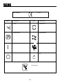
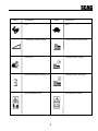
ISO Symbols
SYMBOL
CE Mark
DESCRIPTION
SYMBOL
DESCRIPTION
Choke
Transmission
Parking Brake
Spinning Blade
48071S
On/Start
Spring Tension on Idler
Off/Stop
Oil
WARNING
Falling Hazard
FALLING HAZARD
USE ONLY SCAG APPROVED
RIDING ATTACHMENTS
SEE OPERATOR'S MANUAL
2
481109
SYMBOL
DESCRIPTION
SYMBOL
DESCRIPTION
Fast
Slow
Continuously variable - Linear
Cutting element - Basic symbol
Pinch Point
Cutting element - Engage
Hourmeter/elapsed operating hours
Cutting element - Disengage
Keep bystanders away
Read operator's manual
481039S
3
BEFORE OPERATING
WHILE OPERATING
1. Know the controls and how to stop quickly.
1. Start the engine when the neutral latches are in the
neutral lock position, the cutter blades are disengaged, and the transmission is in neutral.
2. Do not allow children to operate the machine. Do
not allow adults to operate the machine without
proper instruction.
2. Do not run the engine in a confined area without
adequate ventilation. Exhaust fumes are hazardous and could possibly be deadly.
3. Remove all debris or other objects that might be
picked up and thrown by the cutter blades. Keep
all bystanders away from the mowing area.
3. Using the machine demands attention. To
prevent loss of control:
A. Mow only in daylight or when there is good
artificial light.
B. Watch for holes or other hidden hazards.
C. Do not drive close to a drop-off, ditch, creek
bank, or other hazard.
D. Reduce speed when making sharp turns and
when turning on hillsides.
E. Always be sure of your footing. Keep a firm
hold on the handles and walk---never run.
F. Do not operate where conditions are slippery.
4. Keep all shields, safety devices, and decals in
place. If a shield, safety device or decal is
defective or damaged, repair or replace it before
operating. Also, check all nuts, bolts and screws
for proper tightness, to assure the machine is in
safe operating condition.
5. Do not operate the machine while wearing sandals, tennis shoes, sneakers or shorts. Also, do
not wear loose fitting clothing which could get
caught in moving parts. Always wear long pants
and substantial shoes. Wearing safety glasses and
safety shoes is advisable and required by some
local ordinances and insurance regulations.
4. The discharge chute must always be installed and
in the down position on the side discharge cutter
deck except when the Scag optional grass catcher
or mulching plate are properly installed. If the
discharge area should plug, shut the engine off
and wait for all movement to stop before removing the obstruction.
6. Fill the fuel tank with clean, fresh gasoline, with a
minimum octane rating of 87. Avoid spilling
gasoline. Gasoline is highly flammable, handle it
carefully.
A. Use an approved gasoline container.
B. Do not fill the tank while the engine is hot or
running.
C. Do not smoke while handling gasoline.
D. Fill the fuel tank outdoors and up to approximately 1" (25 mm) below the bottom of the
filler neck.
E. Wipe up any spilled gasoline.
5. Disengage the blades and wait for them to stop
before crossing gravel drives, walks or roads.
6. Shut the engine off and wait until the blades come
to a complete stop before removing the grass
catcher container.
7. Never raise the cutter deck while the blades are
rotating.
7. Before attempting to start the engine, shift the
transmission into neutral, move the blade engagement switch to the OFF position, and move the
neutral latches to neutral.
8. Always park the mower and/or start the engine on
a level surface.
4
14. Use only Scag approved riding attachments.
9. If the cutting blades should strike a solid object
or the equipment should start to vibrate abnormally, stop the engine, disconnect the spark plug
wire, and check immediately for the cause.
Vibration is generally a warning of trouble.
Check the machine for damaged or defective
parts. Repair any damage before starting the
engine or operating the cutter deck. Be sure the
blades are in good condition and the blade bolts
are tight.
Scag Approved Riding Attachments:
RS-2
RS-ZT
Using unapproved attachments, (especially "standup" riding attachments) may be hazardous.
MAINTENANCE AND STORAGE
1. Disconnect the spark plug wire from the spark
plug to prevent accidental starting of the engine
when servicing, adjusting or storing the machine.
10. Reduce speed and exercise extreme caution on
slopes and in sharp turns to prevent tipping or
loss of control. Be especially cautious when
changing directions on slopes.
2. If the mower must be tipped to perform maintenance or adjustment, remove the battery if it has
one, drain the gasoline from the fuel tank and the
oil from the crankcase.
WARNING:
DO NOT operate on steep slopes. To check a
slope, attempt to back up it (with the cutter deck
down). If the machine can back up the slope
without the wheels slipping, reduce speed and
use extreme caution. ALWAYS FOLLOW OSHA
APPROVED OPERATION.
3. To reduce potential fire hazard, keep the engine
free of excessive grease, grass, leaves and
accumulations of dirt.
4. Be sure the machine is in safe operating condition
by keeping nuts, bolts, and screws tight. Check
the blade mounting bolts and nuts frequently to be
sure they are tightened.
11. Do not touch the engine or muffler while the
engine is running or soon after it is stopped.
These areas could be hot enough to cause a burn.
5. If the engine must be running to perform a maintenance adjustment, keep hands, feet, clothing and
other parts of the body away from the cutter deck
blades and other moving parts.
12. Before leaving the operators position or leaving
the mower unattended, shift the transmission into
neutral, place the neutral latches in the neutral
lock position, and move the blade engagement
switch to OFF. Shut the engine OFF and remove
the key.
6. Do not overspeed the engine by changing governor settings. To be sure of safety and accuracy,
have an authorized dealer check maximum engine
speed with a tachometer.
13. Do not pass or stand on the grass discharge side
of any mower with the engine running. Stop
operation when another person approaches.
7. The engine must be shut off before checking the
oil or adding oil to the crankcase.
8. Allow the engine to cool before storing the
mower in any enclosure such as a garage or
storage shed. Make sure the fuel tank is empty if
the machine is to be stored in excess of 30 days.
Do not store the mower near any open flame or
where gasoline fumes may be ignited by a spark.
WARNING
FALLING HAZARD
USE ONLY SCAG APPROVED
RIDING ATTACHMENTS
SEE OPERATOR'S MANUAL
481109
5
9. Always store gasoline in a safety-approved, red
container.
MOWER OPERATION
1. Read and understand the safety instructions
before attempting to operate this machine.
10. Be careful when servicing the battery as it contains acid, which is corrosive and could cause
burns to skin and clothing.
2. Before starting the engine:
* Check the oil level in the engine.
* Fill the fuel tank with clean, fresh, lead-free
gasoline.
* Open the fuel valve on the bottom of the fuel
tank.
11. Batteries release explosive gases when being
charged or discharged. Keep batteries away from
any source of sparks and/or flame.
INITIAL RUN-IN PROCEDURES (FIRST
DAY OF USE OR APPROXIMATELY 10
HOURS)
-NOTEUse gasoline with an octane rating no less than
87.
1. Check the belts for proper tension at 2, 4 and 8
hours. Check for abnormal wear and adjust as
needed.
* The transmission must be in NEUTRAL.
* The blade clutch switch must be in the OFF
position.
* The operator's presence levers must be
released.
* The neutral latches must be in the neutral lock
position.
* The key switch must be on.
2. Check the steering control rods for neutral
adjustment. (See Adjustments, page 7)
3. Check the tires for proper pressure.
Caster Wheels
25 psi.
Drive Wheels
15 psi.
3. Start the engine:
4. Check for loose hardware. Tighten as needed.
* Choke as required. If the engine is cold, pull
the choke knob out. When the engine starts,
slowly push the choke in. If the engine stalls,
repeat the above operation. When the engine
is warm, choking may not be necessary.
5. Check the safety switches for proper adjustment:
* The engine will crank, but not start if the
machine is not in neutral.
* On electric start machines, the engine will
not crank if the PTO switch is on.
* The engine should crank and start if the
machine is in neutral and the PTO
engagement switch is OFF.
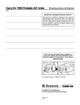
4. Engage the cutter blades by pulling the blade
clutch switch into the ON position. Push the
switch to the OFF position to disengage the cutter
blades.
6. Apply lubricant to all the grease fittings.
Lubricant was applied at the factory. This is
just a precautionary check to make sure that
all the fittings have been lubricated properly.
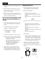
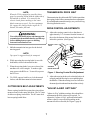
PULL UP TO ENGAGE
PUSH DOWN TO DISENGAGE
390S0138
6
-NOTEWhen the PTO is engaged or (possibly) disengaged, a squealing sound from the underside of
the machine is normal. It is caused by the
electric clutch plates meshing as the cutter
blades come up to speed. For best equipment
life, engage the clutch with the engine at 1/2
throttle, not under full load.
TRANSMISSION DRIVE BELT
The transmission drive belt on the SWU belt drive machine
has a spring-loaded idler system and needs no adjustment.
If you find that the transmission slips, see your local Scag
Servicing Dealer for service.
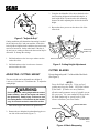
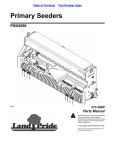
DRIVE CONTROL ADJUSTMENTS
1. Adjust the steering control rods so that there is
approximately 3/4" clearance from the bottom of
the rod to the bottom of the neutral latch slot when
in the drive position. (See Figure 1)
WARNING:
To avoid serious bodily injury and damage to the
transmission, the machine must be at a full stop
before shifting between gears or shifting
between forward and reverse.
NEUTRAL
LATCH
5. Shift the transmission into gear for the desired
mowing speed.
-NOTETop speed is suggested only for transport!
NEUTRAL LOCK
POSITION
DRIVE POSITION
6. While squeezing the steering brake levers with
both hands, release both neutral latches.
3/4"
7. When the steering brake levers are released, the
machine will travel straight. To make a right
turn, squeeze the RH lever. To turn left, squeeze
the LH lever.
STEERING
BRAKE LEVER
SC404GB
Figure 1. Steering Control Rod Adjustment
2. Adjust the steering brake rods so that the brakes do
not apply until the steering levers are pulled tight to
the handles. When the steering levers are locked in
the neutral position the machine should move freely.
8. TO STOP, squeeze both levers, lock the neutral
latches, and shift the transmission into neutral.
CUTTER DECK BELT ADJUSTMENTS
"ADJUST-A-GRIP SETTINGS"
Due to a spring-loaded idler system, there is no adjustment necessary for the cutter deck belts. The 36" cutter
deck has one spring-loaded idler. The 48" cutter deck
has two spring loaded idlers.
"Adjust-A-Grip," with three settings, allows hand force
adjustment in the field, with no tools required. To
operate the "Adjust-A-Grip", pull back on the handle
and move the lever up or down depending on the
amount of belt force needed (See Figure 2, page 8).
7
3. Using the deck handles, lift or lower the deck to the
desired cutting height and reinstall the hairpins. A
deck height decal is located on the deck mounting
frame as an aid in adjusting the deck to the desired
height.
4. Repeat the above process on the other side of the
cutter deck.
SWU99AG
Figure 2. "Adjust-A-Grip"
Cutting conditions will determine what setting is needed
for the Adjust-A-Grip" and your machine. If the drive
belts slip due to high moisture conditions, the tension may
need to be increased. On the other hand, if the day is
dry and you are cutting on flat terrain the tension may be
decreased. To change the settings:
Lift deck with
handles only
1. Pull back and move the lever up to reduce tension
on the drive belt.
Remove Hair Pins
2K SWU DHA
Figure 3. Cutting Height Adjustment
2. Pull back and move the lever down to increase
tension on the drive belt.
CUTTER BLADES
ADJUSTING CUTTING HEIGHT
Do not sharpen beyond 1/3 of the width of the blade.
(See Figure 3)
The mower deck can be adjusted from a height of
1-inch to 4-1/2 inches at 1/2-inch intervals. To adjust the
cutting height:
-NOTEDress the blade with a file. Using a wheel
grinder may burn the blade. Check the balance
of the blade. If blades are out of balance,
vibration and premature wear of spindle assembly can occur. See your authorized Scag dealer
for blade balancing or special tools if you
choose to balance your own blades.
WARNING:
Do not adjust the cutting height with the mower
blades rotating. Shut off the engine and remove
the ignition key. Bodily injury could occur from
the rotating blades. Lift cutter deck by the handles
only. Do not reach under the cutter deck to lift it.
ANGLE BLADE BACK
1. Shut off the engine and remove the ignition key.
DO NOT CUT IN
X
2. Remove the two hairpins from the adjusting pins on
one side of the cutter deck (Figure 3).
30
X MUST NOT EXCEED
1/3 BLADE WIDTH
SC4O8G
8
Figure 4. Blade Sharpening
LUBRICATION & MAINTENANCE
+ Grease spindle until grease comes out the relief valve.
BREAK-IN
8 HOURS (DAILY)
Compatible Greases:
Lidok EP #2 (found at industrial shops)
Ronex MP (Exxon service stations)
Shell Alvania (Shell service stations)
Mobilux #2 (Mobil service stations)
40 HOURS (WEEKLY)
100 HOURS (BIWEEKLY)
COMMENTS
PROCEDURE
X
X
X
X
X
X
X
X
X
X
Check all hardware for proper tightness
Change engine oil and filter at 5 hours
Check engine oil
Remove debris from under belt cover
Sharpen cutter blades
Grease spindle bearings
Clean air filter
Check belt wear
Check tire pressure
Change engine oil
Replace air filter
Grease caster wheel bearings
Grease caster wheel pivot shafts
Grease drive wheel bearings
Grease transmission couplers
Grease idler bracket LH & RH
Check all hardware for proper tightness
X
X
X
X
X
X
X
X
Do not over fill
More often if needed
More often if needed
+ US Lithium MP White Grease 2125
More often if needed
Add or adjust as required
See engine mfg. information
More often if needed
Chassis grease
Chassis grease
Chassis grease
Chassis grease
Chassis grease
More often if needed
Adjust air gap on electric clutch
Contact your Scag dealer for information about
making this adjustment.
9
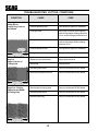
TROUBLESHOOTING CUTTING CONDITIONS
CAUSE
CONDITION
Stringers - Occasional
Blades of Uncut
Grass
Width of Deck
CURE
Low engine RPM
Run engine at full 3600 RPM
Ground speed too fast
Slow speed to adjust for conditions
Wet grass
Cut grass after it has dried out
Dull blades, incorrect sharpening
Sharpen blades
Deck plugged, grass accumulation
Clean underside of deck
Belts slipping
Adjust belt tensions
Dull, worn blades
Sharpen blades
Incorrect blade sharpening
Sharpen blades
Low engine RPM
Run engine at full 3600 RPM
Belt slipping
Adjust belt tension
Deck plugged, grass accumulation
Clean underside of deck
Ground speed too fast
Slow speed to adjust for conditions
Wet grass
Cut grass after it has dried out
Bent blades
Replace blades
Not enough overlapping
between rows
Increase the overlap of each
pass
SGB020
Streaking - Strips of
Uncut Grass in Cutting
Path
Width of Deck
SGB018
Streaking - Strips of
Uncut Grass Between
Cutting Paths
Width
of
Deck
SGB019
Width
of
Deck
10
TROUBLESHOOTING CUTTING CONDITIONS
CAUSE
CONDITION
Uneven Cut on Flat
Ground - Wavy
High-Low
Appearance,
Scalloped Cut, or
Rough Contour
CURE
Lift worn off of blade
Replace blade
Blade upside down
Mount with cutting edge toward
ground
Deck plugged, grass accumulation
Clean underside of deck
Too much blade angle (deck pitch)
Adjust pitch and level
Deck mounted improperly
See your authorized SCAG dealer
Bent spindle area
See your authorized SCAG dealer
Dull blade
Sharpen blade
Uneven ground
May need to reduce ground speed,
raise cutting height, and/or change
direction of cut
Tire pressures not equal
Check and adjust tire pressure
Wheels uneven
Check and adjust tire pressure
Deck mounted incorrectly
See your authorized SCAG dealer
Width of Deck
SGB020
Uneven Cut on
Uneven Ground Wavy Appearance,
High-Low Scalloped
Cut, or Rough Contour
Width of Deck
SGB021
Sloping Ridge Across
Width of Cutting Path
Width of Deck
SGB023
11
TROUBLESHOOTING CUTTING CONDITIONS
CAUSE
CONDITION
Scalping - Blades
Hitting Dirt or
Cutting Very Close to
the Ground
Width of Deck
CURE
Low tire pressures
Check and adjust pressures
Ground speed too fast
Slow speed to adjust for conditions
Cutting too low
May need to reduce ground speed,
raise cutting height, change direction
of cut, and/or change pitch and level
Rough terrain
May need to reduce ground speed,
raise cutting height, and/or change
direction of cut
Ground speed too fast
Slow speed to adjust for conditions
Wet grass
Cut grass after it has dried out
Blades not mounted evenly
Adjust pitch and level
Bent blade
Replace blade
Internal spindle failure
See your authorized SCAG dealer
Mounting of spindle incorrect
See your authorized SCAG dealer
Bent spindle mounting area
See your authorized SCAG dealer
Internal spindle failure
See your authorized SCAG dealer
Bent deck housing
See your authorized SCAG dealer
SGB022
Step Cut
Ridge in Center of
Cutting Path
Width of Deck
SGB024
Slope Cut - Sloping
Ridges Across Width
of Cutting Path
Width of Deck
SGB025
12
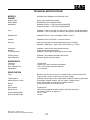
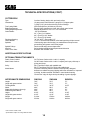
TECHNICAL SPECIFICATIONS
MODELS
ENGINE
SWU36A-15KA, SWU48A-17KA, SWU52A-17KA
General Type:
Brand / Model:
Horsepower:
Heavy duty industrial/commercial
Kawasaki FH451V, Kawasaki FH500V
Kawasaki FH451V = 15HP maximum @ 3600 RPM
Kawasaki FH500V = 17HP maximum @ 3600RPM
Type:
Kawasaki = 15HP 4 cycle gas, air cooled, V twin cylinder, vertical shaft engine
Kawasaki = 17HP 4 cycle gas, air cooled, V twin cylinder, vertical shaft engine
Displacement:
Kawasaki FH451V = 426 cc; Kawasaki FH500V = 494 cc
Cylinder:
Kawasaki FH451V & FH500V = 2 cast-iron sleeves
Governor:
Mechanical type governor with variable speed control. Settings:
Kawasaki = 3600 rpm(+/- 75rpm), idle set at 1550 rpm (+/- 75 rpm)
Air Cleaner:
Exhaust:
Fuel Pump Group:
Kawasaki = Semi-cyclone type with dual element
Single canister side mount muffler.
Kawasaki = Pulse-type fuel pump with in-line fuel filter
Oil Pump Group:
Starter/Electrical:
Kawasaki = Full pressure lubrication with oil filter
Electronic ignition with recoil starter
ENGINE DECK
Thickness:
Fuel Tank:
Drive Wheels/Tires:
Handle Bars:
7 gauge steel.
5 gallon (19.0 liters) seamless polyethylene.
15.0 x 6.0-6 two-ply pneumatic tubeless.
1-1/4" diameter.
DRIVE SYSTEM
Type:
Transmissions:
Steering/Travel Control:
Brakes:
Axles:
Wire Harness:
Safety Group:
Forward Speed Range:
Reverse Speed Range:
Belt drive with twin power belts for increased friction to pulley surface and
"Adjust-A-Grip" traction control lever with three settings
Peerless 5-speed transmission, Model #700-070A with 9 spline coupler shaft
Clutch/brake fingertip steering, key lock switch. ("Adjust-A-Grip"
design allows minimum hand force to operate controls)
6" drum, band brake, one on each wheel.
1"
14 gauge wire.
Hand actuated operator presence system with blade clutch and
transmission interlock to engine kill
1.5 to 7.0 mph
3.0 mph
Date of Issue: October, 2000
Specifications Subject to Change Without Notice
13
TECHNICAL SPECIFICATIONS (CON'T)
CUTTER DECK
Type:
Construction:
True Cutting Width:
Blade Engagement:
Cutting Height Adjustment:
Cutter Blades:
Discharge Opening:
Caster Wheels:
Spindles:
Spindle Pulleys:
Idler Arm:
Cutter Deck Belts:
Out-front floating design with anti-scalp rollers.
10-gauge steel reinforced with 7-gauge (3/16") Support plate.
7-gauge (3/16") deck skirt with easy clean-out design.
36.0 inches (90.2cm), 48.0 inches (122.0cm)
Electric blade engagement clutch with control panel switch
Manual adjustment 1" to 4-1/2" in 1/2" increments
.197 Thick Marbane
36" = Two (2) 18" blades
48" = Three (3) 16.5" blades
52" = Three (3) 18" blades
36", 48" & 52" = Extra wide 11.5"
11 x 4.5-5 smooth-tread flotation, roller bearings with quick pin removal
Cast housing, taper roller bearing, low maintenance with top access
grease fitting and grease overfill relief poppet.
Cast-iron with easily removed taper hubs
Spring-loaded self adjusting with permanent lubrication
B-section with Kevlar® cord.
ADDITIONAL SPECIFICATIONS
OPTIONAL ITEMS/ATTACHMENTS
Fabric Grass Catcher:
Metal Grass Catcher:
Sulky:
Mulch Master
GC-F4 Grass Catcher with 4 cubic ft. capacity
GC-4D Grass Catcher with 4 cubic ft. capacity and rope pull dump or
pickup and dump.
RS-2 Two-Wheel Sulky with padded seat.
RS-ZT Two-Wheel Zero-Turn Sulky with padded seat.
Provides individually baffled chambers with specially designed
deflectors to redistibute grass clippings within the chambers for improved
mulching. Includes serrated "Eliminator" cutter blades featuring
"Double-Cut" edge for high velocity shredding of grass clippings.
APPROXIMATE DIMENSIONS
SWU36A
SWU48A
SWU52A
Length:
Length with grass catcher:
Tracking Width:
Width:
Width (with discharge chute up):
Width with grass catcher:
Height:
Height with grass catcher:
Weight:
Weight with grass catcher:
79.5"
79.5"
34.75"
48.0"
38.0"
56.0"
41.25"
41.25"
513 lbs.
553 lbs.
74.0"
74.0"
34.75"
59.0"
49.0"
68.0"
41.25"
41.25"
578 lbs.
618 lbs.
75"
75"
34.75"
64"
53"
72"
41.25"
41.25"
643 lbs.
686 lbs.
Date of Issue: October, 2000
Specifications Subject To Change Without Notice
14
NOTES
15
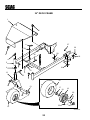
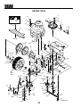
36" CUTTER DECK
45
48
63
53
49
48
49
62
50
45
44
44
50
59
42
51
46
58
60
47
43
52
32
50
57
51
61
53
56
54
34
42
To"A"
41
55
50
47
41
"A"
13
40
36
39
13 34
37
39
64
33
1
38
2
4
20
3
21
35
22
5
7
24
13
8
6
31
12
5
23
32
14
11
26
9
25
16
10
15
9
27
19
19A
22
17
28
18
29
2001-SWU-CD36 30
16
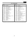
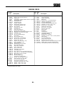
36" CUTTER DECK
Ref. Part
No. Number
Description
1
2
3
4
5
6
7
8
9
10
11
12
13
14
15
16
17
18
19
19A
20
21
22
23
24
25
26
27
28
29
30
31
32
Cutter Deck (Includes Decals)
Capscrew, 3/8-16 x 1.0"Serrated Flange Hex Hd
Bracket, Anti-Scalp Wheel
Lock Nut, 3/8-16 Center Lock
Bushing, 376 ID Oilite
Wheel, Anti-Scalp (Incl. Item 5)
Bolt, Carriage 3/8-16 x 4.0"
Pin Assy., Deck Adj. (Incl. Items 10 & 11)
Spacer, Deck Adjustment Pin
Rod End, Male 3/8-24 RH Thread
Nut, 3/8-24 Jam
Spindle Assembly
Nut, 5/16-18 Elastic Stop
Key,1/4 x 1/4 x 2.0"
Bolt, Hex Head 5/16-18 x 1.50"
Spacer, Spindle
Flatwasher, 5/8 W
Bolt, Hex Head 5/8-11 x 9.50"
Cutter Blade, 18"
Cutter Blade, 18" Hi Lift
Spindle Shaft
Seal, Cutter Spindle Top
Tapered Bearing Set (Two Bearings W/Race)
Grease Fitting
Relief Fitting, Cutter Spindle
Spindle Housing
Spacer, Outside
Spacer, Inside
Seal, Cutter Spindle Bottom
Spindle Bushing
Nut, Spindle
Belt Cover, LH
Wing Nut, 3/8-16
461363
04017-27
422478
04021-05
48100-15
481632
04003-26
481838
43512
481539
04020-25
46631
04021-10
04063-08
04001-10
43309
04040-10
04001-41
481707
48185
43299
481024
481022
48114-04
48677
43294
43312
43296
481025
43297
481035
422762
481625-01
Ref. Part
No. Number
33
34
35
36
37
38
39
39
40
41
42
43
44
45
46
47
48
49
50
51
52
53
54
55
56
57
58
59
60
61
62
63
64
04021-09
04110-03
04001-31
43515
04060-08
48038
04001-12
04001-11
451118
48926
48924
481880
04015-14
04020-09
482245
04021-10
04021-09
04043-04
04019-04
461291
04001-51
04001-136
43510
04001-62
422713
04003-04
461174
48224
04001-154
422763
481597
481962
04030-03
Description
Nut, 3/8-16 Elastic Stop
U-Nut, 3/8-16
Bolt, Hex Head 3/8-16 x 2.50"
Pin, Deck Adj. Rear
Pin, Sloted Spring 3/16 x 1.50"
Guide, Roller
Bolt, Hex Head 5/16-18 x 1.75" Front
Bolt, Hex Head 5/16-18 x 1.50" Rear
Roller Shaft
Tapered Hub
Pulley
Belt, Cutter Deck
Capscrew, Socket Head. 1/4-20 x 1.375"
Hex Nut, 5/8-11
Spring, Chute Return
Hex Nut, 5/16-18 Elastic Stop
Hex Nut, 3/8-16 Elastic Stop
Flatwasher, 3/8 (.938 x .391 x .105) Grade 8
Nut, 3/8-16 Serrated Flange
Discharge Chute, Nylon
Capscrew, Hex Head 3/8-16 x 3.75"
Capscrew, Hex Head 3/8-16 x 1.50" Grage 8
Pivot, Idler - Long
Capscrew, Hex Head 38/16 x 3.25"
Base, Idler Pivot
Bolt, Carriage 5/16-18 x 1.0"
Idler Arm Weldment
Ball Bearing
Bolt, Hex Head 5/16-18 x 4.75"
Belt Cover, RH
Spring, Deck Idler
Pulley, Idler
Lockwasher, 5/16 (.317 x .586 x .078)
* Common hardware which should be purchased locally. All bolts are Grade 5 plated, all other fasteners zinc plated.
17
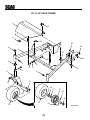
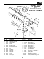
48" & 52" CUTTER DECKS
8
8
51
52
71
52
9
51
67
9
18
56
10
46
18
17
51
61
62
68
13
52
48
"D"
9
46
57
49
50
53
41
54
14
17
59
To"B"
55
48
47
18
60
To "C"
60
46
17
59
45
18
43
59
44
"A"
To "D"
64
58
18
43
1
71
42
"B"
2
59
18
3
70
30
63
31
69
8
4
9 19
5
32
35
6
4
33
20
7
9
65
10
34
66
18
21
11
22
12
17
29
25
27
14
28
28A
16
26
To"A"
36
37
23 22
"C"
13
41
24
15
2001-SWU-CD48, 52
18
32
38
39
40
48" & 52" CUTTER DECKS
Ref. Part
No. No.
1
461368
461373
2
04017-27
3
04021-05
4
48100-15
5
481632
6
422478
7
04003-26
8
04021-09
9
04043-04
10 48224
11 461175
12 43503
13 04003-04
14 422713
15 04001-31
16 04001-45
17 04001-136
18 04019-04
19 48181
20 481838
21 04020-25
22 43512
23 481539
24 46631
25 43309
26 04001-41
27 04040-10
28 481706
28 481707
28A 481710
28A 481711
29 04001-10
30 43298
31 481024
32 481022
33 48114-04
34 43294
Ref. Part
No. No.
Description
Cutter Deck With Decals 48"
Cutter Deck With Decals 52"
Capscrew, 3/8-16 x 1.0" Serrated Flange
Lock Nut, 3/8-16 Center Lock
Bushing, 376 ID Oilite
Wheel, Anti-Scalp
Bracket, Anti-Scalp Wheel
Bolt, Carriage 3/8-16 x 4.0"
Hex Nut, 3/8-16 Elastic Stop
Flatwasher, 3/8 (.938 x .391 x .105) Grade 8
Ball Bearings
Idler Arm RH
Pivot, Idle - Short
Bolt, Carriage 5/16-18 x 1.0"
Base, Idler Pivot
Capscrew, Hex Head 3/8-16 x 2.50"
Capscrew, Hex Head 3/8-16 x 2.0"
Capscrew, Hex Head 3/8-16 x 1.50" Grade 8
Nut, 3/8-16 Serrated Flange
Pulley, Idler
Pin Assembly (Incl. 21 & 23)
Nut, 3/8-24 Jam
Spacer, Deck Adjustment Pin
Rod End, Male 3/8-24
Spindle Assembly
Spacer, Spindle
Bolt,Hex Head 5/8-11 x 9.50"
Flatwasher, 5/8 W
Cutter Blade 16-1/2" 48"
Cutter Blade 18" 52"
Cutter Blade 16-1/2" Hi Lift 48"
Cutter Blade 18" Hi Lift 52"
Bolt, Hex Head 5/16-18 x 1.50"
Spindle Shaft
Seal, Cutter Spindle - Top
Tapered Bearings (Two)
Grease Fitting
Spindle Housing
35
36
37
38
39
40
41
42
43
43
44
45
46
47
48
49
50
51
52
53
53
54
55
56
57
58
59
60
61
62
63
64
65
66
67
68
69
70
71
48677
43312
43296
481025
43297
481035
481625-01
451118
04001-12
04001-11
04060-08
43515
48926
48038
48924
48923
481922
04015-14
04020-09
48087
48285
422745
04001-62
461174
04001-51
461291
04019-03
481597
04001-154
482245
04021-09
04021-10
04001-31
04063-08
481962
43510
422744
04110-03
04030-03
Description
Relief Fitting, Cutter Spindle
Spacer Outside
Spacer, Inside
Seal, Cutter Spindle - Bottom
Spindle Bushing
Nut, Spindle
Wing Nut, 3/8-16
Roller Shaft
Bolt, Hex Head 5/16-18 x 1.0" Front
Bolt, Hex Head 5/16-18 x 1.50" Rear
Pin, Slotted Spring 3/16 x 1.50"
Pin, Deck Adjustment Rear
Tapered Hub
Guide, Roller
Pulley
Pulley, 5.75 Double Groove
Belt, Deck Drive
Capscrew, Socket Head 1/4-20 x 1.375"
Hex Nut, 5/8-11
Belt, RH Blade Drive 48"
Belt, RH Blade Drive 52"
Belt Cover, RH
Capscrew, Hex Head 3/8-16 x 3.25"
Idler Arm Weldment
Capscrew, Hex Head 3/8-16 x 3.75"
Discharge Chute, Nylon
Nut, 5/16-18 Serrated Flange
Spring, Deck Idler
Bolt, Hex Head 5/16-18 x 4.75"
Spring, Chute Return
Nut, 3/8-16 Elastic Stop
Nut, 5/16-18 Elastic Stop
Bolt, Hex Head 3/8-16 x 2.50"
Key, 1/4 x 1/4 x 2.0"
Pulley, Idler
Pivot, Idler - Long
Belt Cover LH
U-Nut, 3/8-16
Lockwasher, 5/16 (.317 x .586 x .078)
* Common hardware which should be purchased locally. All bolts are Grade 5 plated, all other fasteners zinc plated.
19
36"
36"DECK
DeckFRAME
Frame
1
2
6
27
26
30
28
3
22
25
4
5
4
7
24
11
10
9
12
8
7
16
14
13
17
18
19
20
29
21
23
17
15
SWU99DF36
20
36" DECK FRAME
Ref. Part
No. No.
Description
1
2
3
4
5
6
7
8
9
10
11
12
13
14
15
16
17
18
19
20
21
22
23
24
25
26
27
28
29
30
Belt Cover With Decal
Knob With Stud
Knob, Deck Cover Mounting
Bushing, Caster
Frame Weldment, Deck Mounting - 36"
Hair Pin Cotter, .177 x 3.25"
Grease Fitting Str. 1/4-28 Self Tap
Quick Pin .438 Dia
Nut, Push-On - 3/8 Thd.
Flatwasher, 3/8 - (.391 x .938 x .105)
Nut, 3/8-16 Serrated Flange Hex Head
Yoke, Caster Wheel
Capscrew, Hex Head 1/2-13 x 6.50"
Locknut, 1/2-13 Elastic Stop
Wheel Assembly, Caster
Tire, 11 x 4.00-5
Retainer
Roller Bearing
Rim, 5.0 x 2.75 With Zerk & Valve
Grease Fitting Str.1/4-28
Roller Bearing .625 x 3.25"
Capscrew, Hex Head 3/8-16 x 2.25"
Tire Valve, Purchase Locally
Retaining Ring 1.50 Ext.
Bushing, Deck Adjustment Pin
Capscrew, Hex Head 7/16-14 x 1.0"
Nut, 7/16-14 Serrated Flange Hex
U-Nut, 3/8-16
Sleeve, Caster Wheel
Flatwasher, 5/8 - (.688 x 1.75 x .134)
461170
481625-01
04029-03
48100-08
451097
04062-04
48114-04
04066-01
04024-02
04041-07
04019-04
45325
04001-80
04021-07
481843
481845
481770
481846
481844
48114-05
481769
04001-46
**
04050-16
43530
04017-42
04019-05
04110-03
43511
04040-10
* Common hardware which should be purchased locally. All bolts are Grade 5 plated, all other fasteners zinc plated.
** Purchase Locally.
21
48" 48"
& 52"Deck
DECKFrame
FRAME
1
2
3
22
26
4
25
30
5
27
24
28
4
6
10
8
7
9
23
6
11
12
13
16
17
18
19
29
16
15
21
14
20
22
SWU99DF48
48" & 52" DECK FRAME
Ref. Part
No. No.
Description
1
1
2
3
4
5
5
6
7
8
9
10
11
12
13
14
15
16
17
18
19
20
21
22
23
24
25
26
27
28
29
30
Belt Cover With Decal - 48"
Belt Cover With Decal - 52"
Knob With Stud
Knob, Deck Cover Mounting
Bushing, Caster
Frame Weldment, Deck Mounting - 48"
Frame Weldment, Deck Mounting - 52"
Grease Fitting Str. 1/4-28 Self Tap
Quick Pin,.438 Dia
Nut, Push-On - 3/8 Thd.
Flatwasher, 3/8 (.391 x .938 x .105)
Nut, 3/8-16 Serrated Flange Hex Head
Yoke, Caster Wheel
Capscrew, Hex Head 1/2-13 x 6.50"
Locknut, 1/2-13 Elastic Stop
Wheel Assembly, Caster
Tire, 11 x 4.00-5
Retainer
Roller Bearing
Rim, 5.0 x 2.75 With Zerk & Valve
Grease Fitting Str.1/4-28
Roler Bearing .625 x 3.25"
Tire Valve, Purchase Locally
Hair Pin Cotter, .177 x 3.25"
Retaining Ring 1.50 Ext.
Bushing, Deck Adjustment Pin
Capscrew, Hex Head 7/16-14 x 1.0"
Nut, 7/16-14 Serrated Flange Hex
U-Nut, 3/8-16
Capscrew, Hex Head 3/8-16 x 2.25"
Sleeve, Caster Wheel
Flatwasher, 5/8 - (.688 x 1.75 x .134)
461171
461279
481625-01
04029-03
48100-08
451098
451155
48114-04
04066-01
04024-02
04041-07
04019-04
45325
04001-80
04021-07
481843
481845
481770
481846
481844
48114-05
481769
*
04062-04
04050-16
43530
04017-42
04019-05
04110-03
04001-46
43511
04040-10
* Common hardware which should be purchased locally. All bolts are Grade 5 plated, all other fasteners zinc plated.
23
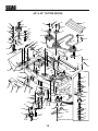
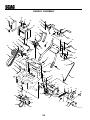
ENGINE DECK
ENGINE DECK
4
34
5
3
15, 17 KA
ONLY
12
57
5A
7
18
13
6
9
8
10
1
To "B"
16
42
18
14
66
2
44
40
41
52
40, 40A
19
43
11
"B"
48
65
17
45
2
39
36
50
16
24
16
48
Pulley
"X"
20
"A"
38
38A
38B
47
39 29
23
28
To "A" 33
26
59
15
25
46
37
56
49
Pulley
"X"
21
27
2
53
22
35
30
31
54
47
32
32A
51
58
55
60
46
62
48
63
61
64
2K SWU ED
2
47
24
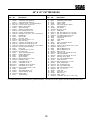
ENGINE DECK
Ref. Part
No. No.
1
1
2
3
4
5
5A
6
7
8
9
10
10
11
12
13
14
15
16
17
18
19
20
21
22
23
24
25
26
27
28
29
30
31
32
32A
33
34
35
36
37
38
38A
38B
39
40
40A
Ref. Part
No. No.
Description
482144
Engine,15HP Kawasaki (FH451V - AS02)
481563
Engine, 17HP Kawasaki (FH500V)
48030-09
Cable Clamp
481580
Transmission, 5-speed (Peerless 700-070, 9 spline)
48231
Neutral Safety Switch
48122-01
Fibre Washer, thin
48122-02
Fibre Washer, thick
481581
Coupler, Jackshaft
48114-05
Grease Fitting, straight 1/4-28
481582
Jackshaft (fits SW32,36 & 48)
04063-09
Key, Hi-Pro #9
422737
Heat Shield, 36" & 48"
422883
Heat Shield, 52"
43085
Wheel Axle (SW36,48) **
481717
Wire Harness Adaptor, 17KA
04017-16
Bolt, 5/16-18 X .75" Serrated Flange Hex Head
04040-14
Flat Washer 1/4" (.312 X .75 X .065)
04030-03
Lock Wshr. 5/16"
04019-04
Nut, 3/8-16 Serrated Flange
46765
Engine Deck
04021-08
Nut, 1/4-20 Elastic Stop
48114-04
Grease Fitting, 1/4-28 Self Tap
04001-51
Bolt, 3/8-16 x 3-3/4" Hex Head
461073
Electric Clutch (Ogura)
04041-07
Washer, 3/8" (.391 x .938 x .105)
48197
Pulley, Transmission Input
04063-07
Key, Woodruff #9
04050-09
Retaining Ring, 5/8" Ext, Basic
48203
Belt, Transmission Drive
481048
Idler Pulley, Transmission
481666
Pulley, Traction Drive
04063-19
Key, 1/4 x 1/4 x 3/4"
04041-28
Flat Washer, 7/16" Special
04030-05
Lock Washer,7/16"
04001-101 Bolt, 7/16-20 x 2-1/2" Hex Head (Kohler Only)
04002-15
Cpsrw, M10-1.5 x 55 Metric Hex Hd (Kawasaki)
04001-12
Bolt, 5/16-18 x 1-3/4" Hex Head
04002-07
Bolt, M8-1.25 x 1.0
04021-09
Nut, 3/8-16 Elastic Stop
*
Valve Stem, Purchase Locally
04018-01
Bolt, M8-1.25 x M25 Metric Hex Hd
481841
Wheel Assembly (incl. 38A-38B)
481842
Tire, 15 x 6.0-6, Turf Saver
481859
Rim & Bearing Assembly (incl. 39)
481858
Wheel Brng. NWC (OD 1.984 - 1.980)
04042-05
Washer, 1-1/16 x 1-3/4 x 12 ga
04041-14
Washer, 1-1/16 x 1-1/2 x 18 ga
* = Purchase Locally
** = Requires welding onto chassis.
25
41
42
43
44
45
46
47
48
49
50
51
52
53
54
55
56
57
58
59
60
61
62
63
64
65
66
66
04050-08
48200
43088
48209
04017-19
04001-22
04021-10
04019-03
04041-07
04001-08
481716
04003-02
461169
422533
48224
43504
04031-09
421370
04003-04
04043-04
422534
04021-05
481835
04001-02
04017-16
12-068-64
49070-7002
Description
Retaining Ring, 1" Ext.- "E"
Pulley, Wheel Drive
Spacer, Wheel Pulley
Brake Drum
Bolt, 5/16-18 x 1-1/2" Serrated Flange
Capscrew, Hex Head 3/8-16 x 2.75"
Nut, 5/16-18 Elastic Stop
Nut, 5/16-18 Serrated Flange Hex Head
Flatwasher, 3/8 (.391 x .938 x .105)
Bolt, 5/16-18 x .75" Hex Head
Rubber Pad, Clutch Stop
Bolt, 1/4-20 x .75" Carriage
Idler Arm, Trans. Drive
Backing Plate
Ball Bearing
Hub Idler Pivot
Lock Washer Internal Tooth
Anti Rotation Bracket
Bolt, 5/16-18 x 1" Carriage
Flatwasher, 3/8 (.391 x .938 x .105 HD) Grade 8
Plate, Backing
Nut, 3/8-16 Elastic Stop
Spring, Return Drive Idler
Bolt, Hex Head 3/8-16 x 2.75"
Capscrew, 5/16-18 x .75 Serrated Flange Hex Head
Muffler, Kohler (Purchase from Kohler Only)
17KA Muffler (Purchase from Kawasaki Only)
HANDLE ASSEMBLY
HANDLE ASSEMBLY
72
24
73
7
71
24
31
8
70
12
44
8
28
75
27
26
29
23
69
50
48
42
66 78
9
30
30A
79
77
80
28
49
51
52
65
20
68
74
66
53
47
1
58
8
45
45A
54
19
55
76
46
25
20
67
11
56
59
3
21
57
61
41
16
22
10
43
13
2
14
13
5
4
17
32
35
14
37
15
15A
60
19
19
82
63
18
33
48
19
22
36
14
38
19
81
19
62
5
34
6
39
19
62
40
26
64
19
2K SWU HA
HANDLE ASSEMBLY
Ref. Part
No. No.
1
2
3
4
5
6
7
8
9
10
11
12
13
14
15
15A
16
17
18
19
20
21
22
23
24
25
26
27
28
29
30
31
32
33
34
35
36
37
38
39
40
41
42
43
Description
49403
Handle Assembly 16" Frame
421360 Belt Guard
04017-27 Capscrw, 3/8-16 x 1" Ser. Flange
04041-07 Flatwasher, 3/8 (.391 x .938 x .105)
04021-09 Nut, 3/8-16 Elastic Stop
481834 Spring, Idler
04001-10 Bolt, 5/16-18 x 1-1/4" Hex Head
04021-10 Nut, 5/16-18 Elastic Stop
04017-05 Capscrew, 1/4-20 x 3/4" Hex Head
44004
Control Rod, Steering
04062-02 Hair Pin, Small
481839 Grip, Shift Lever
43032
Swivel Joint
04062-01 Hair Pin, Large .094 Diameter
45847
Idler Bracket, RH
45846
Idler Bracket, LH
43092
Idler Sleeve
04001-62 Bolt, 3/8-16 x 3/4" Hex Head
04004-17 Support Belt Guard
04019-04 Nut, 3/8-16 Serrated Flange
04019-03 Nut, 5/16-18 Serrated Flange
04017-16 Cpscrw, 5/16-18 x .75" Ser. Flng.
43286
Spacer
48309
Bushing, Fuel Tank
48292
Rubber Pad, (Upper)
46089
Steering Lever
04017-17 Capscrew, 5/16-18 x 1" Ser. Flng.
48312
Bushing, Operator Presence
04040-15 Washer, 5/16 (.375 x .875 x .083)
48951
Spring, Operator Presence
45573
Operator Presence Lever,
LH (Small Frame)
45572
Operator Presence Lever, RH
44005
Brake Rod
45092
Brake Lever
45093
Brake Link
42254
Brake Link Plate
04024-01 Nut, 3/8 Push-on
48114-05 Greese Fitting, Straight 1/4-28
04050-01 Retaining Ring, 5/8 Ext. "E"
48210
Brake Band
04001-45 Bolt, 3/8-16 x 2" Hex Head
04031-08 1/4" Internal Tooth Lockwasher
04032-01 Curved Spring Washer
04001-32 Bolt, Hex Head 3/8-16 x 1.25"
15KA 17KA
x
x
x
x
x
x
x
x
x
x
x
x
x
x
x
x
x
x
x
x
x
x
x
x
x
x
x
x
x
x
x
x
x
x
x
x
x
x
x
x
x
x
x
x
x
x
x
x
x
x
x
x
x
x
x
x
x
x
x
x
x
x
x
x
x
x
x
x
x
x
x
x
x
x
x
x
x
x
x
x
x
x
x
x
x
Ref. Part
No. No.
44
45
45A
46
47
48
49
50
51
52
53
54
55
56
57
58
59
60
61
62
63
64
65
66
67
68
69
70
71
72
73
74
75
76
77
78
79
80
81
82
04020-02
461242
461241
48205
48202A
48198
48199
04012-04
Description
Nut, 1/4-20 Hex
Neutral Latch, RH
Neutral Latch, LH
Rubber Pad (Lower)
Belt, Wheel Drive
Idler Pulley, Wheel Drive
Pulley, Jackshaft (Inc. 50)
Setscrew, Hex Socket Knurl
Cup Pt. 5/16-18 (nylock)
43098
Spacer, Jackshaft Pulley
48223
Flange, Jackshaft Bearing
48224
Bearing, Jackshaft
04050-09 Retaining Ring, 5/8 Ext. Basic
04017-06 Capscrew, 1/4-20 x 1" Ser. Flange
04001-62 Bolt, 3/8-16 x 3.25"
48030-09 Clamp
04001-17 Bolt, 5/16-18 x 2" Hex Head
482314 Choke Control
04040-15 Flatwasher, 5/16 (.375 x .875 x .083)
04021-02 Nut, 1/4-20 Elastic Stop
43212
Spacer
04001-32 Bolt, Hex Head 3/8-16 x 1.25"
422756 Bar
48058
Fuel Hose,1/4"ID, 20" (KA )
48059-01 Clamp, Fuel Hose
421622 Bracket, Choke Mounting
48159
Grip, Handle
48308
Valve, Fuel Shut Off
46846
Fuel Tank Assy.(Incl. Bush. & Val.)
481603 Fuel Tank Cap
421239 Strap, Fuel Tank
04010-10 Screw, 1/4-20 x 2" Rnd Hd Slotted
422279 Shift Lever
461163 Shift Lever (Incl. Item 12)
48144
Grip, Steering Lever
04041-07 Washer, 3/8 (.391x .938 x .105)
04020-14 Nut, 3/8-24 UNF
48028-05 Cable Tie
04001-53 Bolt, 5/16-18 x 2-1/2"
461304 Lever, Traction Adjustment W/Grip
481847 Grip, Traction Adjustment Lever
15KA 17KA
x
x
x
x
x
x
x
x
x
x
x
x
x
x
x
x
x
x
x
x
x
x
x
x
x
x
x
x
x
x
x
x
x
x
x
x
x
x
x
x
x
x
x
x
x
x
x
x
x
x
x
x
x
x
x
x
x
x
x
x
x
x
x
x
x
x
x
x
x
x
x
x
x
x
x
x
x
x
* Common hardware should be purchased locally. All bolts are Grade 5 plated, all other fasteners zinc plated.
27
INSTRUMENT
PANEL
INSTRUMENT
PANEL
3
7
2A
2B
6
5
4
1
8
SW99IP
Ref. Part
No. No.
1
2
3
4
5
6
7
8
NS
48717
48946
481687
48609
48023
*
04019-01
481678
48030-09
Description
Switch, Neutral Interlock
Throttle Control
Engagement Switch, Electric Clutch
Key Switch (Includes hardware)
Hour Meter (Dealer installed)
Screw, #10-32 x .50 Phillips Washer Head
Nut, #10-32 Serrated Flange Hex Head
Handle Wire Harness, Manual Start
Clamp, Wire Harness
15KA
17KA
x
x
x
x
x
x
x
x
x
x
x
x
x
x
x
x
x
x
* Common hardware which should be purchased locally. All bolts grade 5 plated, all other fasteners zinc plated.
28
PEERLESS 700-070
FOR REFERENCE
ONLY
ORDER PARTS FROM
PEERLESS / TECUMSEH
REF. PART
NO. NO.
DESCRIPTION
1
2
2A
3
8
9
10
11
12
20
21
22
24
25
27
28
29
30
32
34
49
Case, Transmisson
Needle Bearing Grease Spec
Needle Bearing
Case, Transmission
Shift Key
Shift Collar
Shift Rod & Fork
Bevel Gear (42 teeth)
Bevel Pinion (14 teeth-steel)
Steel Ball, 5/16" dia.
Set Screw, 3/8-16 x 3/8"
Spring
Thrust Bearing
Screw, 1/4-20 x 1-1/4" (6)
Retaining Ring
Retaining Ring
Washer (6)
Washer (5)
"O" Ring
Flanged Bushing
Spur Gear (37 teeth)
772083A
780086A
780142
770061A
792089A
784266
784376
778154
778176
792077
792078
792079
780071
792073
792035
788040
780072
780108
792001
780105A
778146A
REF. PART
NO. NO.
50
51
52
53
56
57
58
59
60
65
66
67
71
72
81
82
83
90
150
178
179
29
778125
778239A
778124A
778123A
778145
778151
778240
778126A
778127A
780139
776135
776402
788069
792074
786081
786082
786083
788067B
510334
481581
481582
DESCRIPTION
Spur Rear (35 teeth)
Spur Gear (32 teeth-steel)
Spur Gear (30 teeth)
Spur Gear (25 teeth)
Spur Gear (12 teeth-steel)
Spur Gear (15 teeth)
Spur Gear (18 teeth-steel)
Spur Gear (20 teeth)
Spur Gear (25 teeth)
Washer
Input Shaft (3-11/16" long)
Shifter & Brake Shaft
Square Cut Ring
Threaded Plug (Shipping only, not used)
Roller Chain (No. 41 chain, 24 links)
Sprocket (9 teeth)
Sprocket (18 teeth)
Grease (32 oz. bottle Bentonite grease)
Gasket Eliminator (Loctite #515)
Coupler, Jackshaft (Purchase From Scag)
Jackshaft (Purchase From Scag)
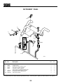
POS
HOURMETER
TO
OPERATOR
PRESENCE
SWITCH
BLK W/RED STRIPE
BLACK
KEY
SWITCH
WHITE
NEG
HOURMETER
BLACK
HANDLE WIRE HARNESS MANUAL START
PART NO. 481678
YELLOW
30
MOWER
ENGAGE
SWITCH
YELLOW
BLACK
BLUE
WHITE
BLK W/RED STRIPE
H
SW99WH481678
TO ENGINE
DECK WIRE
HARNESS
D
F
G
C
E
B
A
BLADE
CLUTCH
NEUTRAL
INTERLOCK
RED STRIPE
BLACK W/RED
E
A
BLACK
BLUE
WHITE
WHITE
YELLOW
F
B
G
C
H
D
GROUND
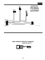
ENGINE DECK
WIRE HARNESS 15 HP KAWASAKI
17 HP KAWASAKI
PART NO. 481073
BLACK
WIRE HARNESS
ADAPTER - ENGINE
INSTRUMENT
PANEL HARNESS
2K SWU WH481073
WIRE HARNESS ADAPTER / KAWASAKI
PART NO. 481717
31
CAUTION
BEFORE OPERATING
MOWER DECK
READ OPERATORS
MANUAL AND SAFETY
INSTRUCTIONS
PULL OUT TO ENGAGE
CAUTION
ON
KEEP BYSTANDERS AWAY
OFF
481684
PUSH IN TO DISENGAGE
481684
R
48314
48314
481863
481905
32
PARKING
BRAKE
FAST
OFF
ON
SLOW
481483
48404
482285
48404
WARNING
INSTALL BELT COVER BEFORE
OPERATING MACHINE
READ OPERATOR'S MANUAL
481039
481039
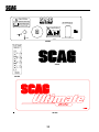
Heavy-Duty
Commercial
MANUFACTURED UNDER ONE OR MORE
OF THE FOLLOWING PATENTS:
4, 487, 006
4, 885, 903
4, 920, 733
4, 967, 543
481971
4, 991, 382
4, 998, 948
5, 118, 617
5, 826, 416
5, 832, 708
5, 865, 018
PATENTS PENDING
481971
48656
33
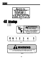
482286
36" - 482297
48" - 481953
52"- 481954
WARNING
FALLING HAZARD
USE ONLY SCAG APPROVED
RIDING ATTACHMENTS
SEE OPERATOR'S MANUAL
481109
R N 1 2 3
4
5
48332
48332
WARNING
DO NOT OPERATE WITHOUT DISCHARGE CHUTE, MULCHING
KIT, OR ENTIRE GRASS CATCHER INSTALLED
482165
482165
34
481109
LIMITED WARRANTY - COMMERCIAL EQUIPMENT
Any part of the Scag commercial mower manufactured by Scag Power Equipment and found, in the reasonable judgment
of Scag, to be defective in materials or workmanship, will be repaired or replaced by an Authorized Scag Service Dealer
without charge for parts and labor. This warranty is limited to the original purchaser and is not transferable. Proof of
purchase will be required by the dealer to substantiate any warranty claims. All warranty work must be performed by an
Authorized Scag Service Dealer.
This warranty is limited to the following specified periods from the date of the original retail purchase for defects in
materials or workmanship:
* Wear items including drive belts, blades, hydraulic hoses and tires are warranted for ninety (90) days.
* Batteries are covered for ninety (90) days.
* Frame and structural components including oil reservoir, fittings, and oil coolers are warranted for 1 year.
* Cutter decks are warranted against cracking for a period of three (3) years. (Parts and labor 1st year; Parts
only 2nd and 3rd year.) The repair or replacement of the cutter deck will be at the option of Scag Power
Equipment. We reserve the right to request components for evaluation. This warranty does not cover any
mower that has been subject to misuse, neglect, negligence, or accident, or that has been operated in any way
contrary to the operating instructions as specified in the Operators Manual.
* Engines and electric starters are covered by the engine manufacturers warranty period.
* Major drive system components (hydraulic pumps and hydraulic motors only) are warranted for two (2)
years by Scag Power Equipment. (Parts and labor 1st year; Parts only 2nd year.) (Two year warranty excludes
fittings, hoses, cooling system, oil reservoir, drive belts, transaxles). The repair or replacement of the
hydraulic pump or hydraulic motor will be at the option of Scag Power Equipment. This warranty does not
cover any mower that has been subject to misuse, neglect, negligence, or accident, or that has been operated in
any way contrary to the operating instructions as specified in the Operators Manual.
* Electric clutches have a Limited Warranty for 2 year (Parts and labor 1st year; Parts only 2nd year).
* Cutter Spindle Assemblies 46631 have a Limited Warranty for three years (Parts and labor 1st year; Parts
only 2nd and 3rd year).
* Any Scag product used for rental purposes is covered by a 90 day warranty.
The Scag mower, including any defective part must be returned to an Authorized Scag Service Dealer within the warranty
period. The expense of delivering the mower to the dealer for warranty work and the expense of returning it to the owner
after repair will be paid for by the owner. Scags responsibility is limited to making the required repairs and no claim of
breach of warranty shall be cause for cancellation or rescission of the contract of sale of any Scag mower.
This warranty does not cover any mower that has been subject to misuse, neglect, negligence, or accident, or that has
been operated in any way contrary to the operating instructions as specified in the Operators Manual. The warranty
does not apply to any damage to the mower that is the result of improper maintenance, or to any mower or parts that have
not been assembled or installed as specified in the Operators Manual and Assembly Manual. The warranty does not
cover any mower that has been altered or modified, changing performance or durability. In addition, the warranty does not
extend to repairs made necessary by normal wear, or by the use of parts or accessories which, in the reasonable judgment
of Scag, are either incompatible with the Scag mower or adversely affect its operation, performance or durability.
Scag Power Equipment reserves the right to change or improve the design of any mower without assuming any obligation to modify any mower previously manufactured. All other implied warranties are limited in duration to the one (1) year
warranty period or ninety (90) days for mowers used for rental purpose. Accordingly, any such implied warranties
including merchantability, fitness for a particular purpose, or otherwise, are disclaimed in their entirety after the expiration
of the appropriate one year or ninety day warranty period. Scags obligation under this warranty is strictly and exclusively
limited to the repair or replacement of defective parts and Scag does not assume or authorize anyone to assume for them
any other obligation. Some states do not allow limitations on how long an implied warranty lasts, so the above limitation
may not apply to you.
Scag assumes no responsibility for incidental, consequential or other damages including, but not limited to, expense for
gasoline, expense of delivering the mower to an Authorized Scag Service Dealer and expense of returning it to the owner,
mechanics travel time, telephone or telegram charges, rental of a like product during the time warranty repairs are being
performed, travel, loss or damage to personal property, loss of revenue, loss of use of the mower, loss of time or inconvenience. Some states do not allow the exclusion or limitation of incidental or consequential damages, so the above limitation or exclusion may not apply to you. This warranty gives you specific legal rights, and you may also have other rights
which vary from state to state.
© 2000
SCAG POWER EQUIPMENT
DIVISION OF METALCRAFT OF MAYVILLE, INC.
PART NO. 03085
PRINTED 10/00
PRINTED IN USA