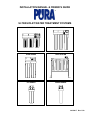
1
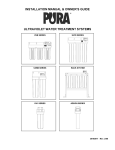
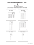
INSTALLATION MANUAL & OWNER’S GUIDE ® ULTRAVIOLET WATER TREATMENT SYSTEMS UVB SERIES UV20 SERIES UVBB SERIES RACK SYSTEM UV1 SERIES ADDON SERIES 36103017 Rev. 5/10 TABLE OF CONTENTS INTRODUCTION DESCRIPTIONS AND DEFINITIONS _________________________________________________ CONDITIONS FOR USE ___________________________________________________________ ROUTINE MAINTENANCE _________________________________________________________ SPECIFICATIONS________________________________________________________________ i i ii ii INSTALLATION MOUNTING BRACKET AND PLUMBING _____________________________________________ 1 UVB SERIES INSTALL CONTROL MODULE______________________________________________________ INSTALL QUARTZ SLEEVE AND DISINFECT SYSTEM__________________________________ INSTALL ULTRAVIOLET LIGHT AND FILTERS ________________________________________ ACTIVATE SYSTEM ______________________________________________________________ SERVICE REQUIREMENTS AND RECOMMENDED INTERVALS__________________________ PARTS ILLUSTRATION ___________________________________________________________ PARTS LIST ____________________________________________________________________ 2 2 2-3 3 3 4 4 UV20 SERIES INSTALL CONTROL MODULE______________________________________________________ INSTALL QUARTZ SLEEVE AND DISINFECT SYSTEM__________________________________ INSTALL ULTRAVIOLET LIGHT AND FILTERS ________________________________________ ACTIVATE SYSTEM ______________________________________________________________ SERVICE REQUIREMENTS AND RECOMMENDED INTERVALS__________________________ PARTS ILLUSTRATION ___________________________________________________________ PARTS LIST ____________________________________________________________________ 5 5 5-6 6 6 7 7 UVBB SERIES INSTALL CONTROL MODULE______________________________________________________ INSTALL QUARTZ SLEEVE AND DISINFECT SYSTEM__________________________________ INSTALL ULTRAVIOLET LIGHT AND FILTERS ________________________________________ ACTIVATE SYSTEM ______________________________________________________________ SERVICE REQUIREMENTS AND RECOMMENDED INTERVALS__________________________ PARTS ILLUSTRATION ___________________________________________________________ PARTS LIST ____________________________________________________________________ 8 8 8-9 9 9 10 10 RACK SYSTEM_______________________________________________________________ 11-12 UV1 SERIES DISINFECT SYSTEM _____________________________________________________________ INSTALL ULTRAVIOLET LIGHT AND FILTERS ________________________________________ ACTIVATE SYSTEM ______________________________________________________________ SERVICE REQUIREMENTS AND RECOMMENDED INTERVALS__________________________ PARTS ILLUSTRATION ___________________________________________________________ PARTS LIST ____________________________________________________________________ 13 13 13 13 14 14 ADDON SERIES DISINFECT SYSTEM _____________________________________________________________ 15 INSTALL ULTRAVIOLET LIGHT_____________________________________________________ 15 INSTALL TUBING ________________________________________________________________ 15-16 ACTIVATE SYSTEM ______________________________________________________________ 16 SERVICE REQUIREMENTS AND RECOMMENDED INTERVALS__________________________ 16 PARTS ILLUSTRATION ___________________________________________________________ 17 PARTS LIST ____________________________________________________________________ 17 MAINTENANCE CLEANING AND DISINFECTION ____________________________________________________ 18-19 FILTER REPLACEMENT __________________________________________________________ 19 UV LAMP REPLACEMENT_________________________________________________________ 19 INTRODUCTION – DESCRIPTIONS AND DEFINITIONS You have purchased one of the most technologically advanced Ultraviolet Water Treatment System available anywhere in the world. It has been designed with you, the consumer, in mind. PURA® products are lightweight, easy to use, and simple to maintain. PURA products will provide you with healthy, clean drinking water for years to come. WHAT IS ULTRAVIOLET? WHAT IS ACTIVATED CARBON? Ultraviolet (UV) light from the sun has long been known for its ability to destroy microorganisms. However, it has only been in recent years that equipment producing UV light has been manufactured for residential use. Activated carbon has been used for hundreds of years to treat taste, odor, and color problems in water. Activated carbon has been proven to be an excellent media to produce better tasting water and to remove harmful water contaminants at a reasonable cost. WARNING: NEVER LOOK DIRECTLY AT A LIGHTED UV LAMP. ULTRAVIOLET RAYS CAN BE HARMFUL TO EYES. Carbon used for filters may be manufactured from wood, coal, or coconut shells. The raw carbon is ground up and “activated” by heating the granules at a controlled temperature and pressure. UV energy is produced by low-pressure mercury vapor enclosed in a tubular lamp. While a UV lamp resembles a standard fluorescent lamp, it is similar in appearance only. This process causes the carbon granules to expand and create active sites where pollutants can be collected by adsorption. These new sites dramatically increase the total surface area and capacity of each granule. Energy produced by the UV lamp has the ability to destroy microorganisms that can live in water. There are five major groups of microorganisms that are altered by a specific spectrum of ultraviolet light: viruses, bacteria, fungi, algae, and protozoa. WHAT IS ADSORPTION? Adsorption is the physical process where certain water pollutants are attached to the surface of carbon particles as the water flows through the filter. The pollutants are removed from the water and locked into the carbon granule. When these microbes are exposed to the proper amount of UV energy, their DNA structure is scrambled, and they are unable to reproduce. Since the cell is now sterile or dead, it is no longer a threat. Activated carbon is also able to filter out sediment through a process of mechanical filtration. The particles are captured in the spaces between carbon granules. PURA SYSTEMS PURA recommends that all UV systems include pre-filters to process the water before it reaches the UV lamp. This will ensure that maximum UV exposure is achieved. PURA Ultraviolet Water Treatment Systems are designed for indoor use only. PURA UVB, UV20 and UVBB series offers integrated filters in a single system. These integrated systems use a two-stage filtration process: PURA Systems are designed to provide complete water treatment in a compact, easy-to-use package. Please follow the directions in this Guide exactly when installing your PURA System to ensure that it operates correctly. First, a string-wound filter removes the suspended solids that may shield the microbes and make it difficult to obtain sufficient UV exposure. Second, an activated carbon filter removes unpleasant tastes and odors. The UV lamp requires a start-up period of one to two minutes in order to achieve full intensity. Repeated starting of the UV lamp will shorten its life. Therefore, it is recommended that the UV lamp remain on at all times during use. CONDITIONS FOR USE Source Water Supply Profile Chemical Parameters Max mg/L Feed Water Pressure† 20 – 75psig (138 – 517kPa) Hardness (CaCO3) < 120 (7 gpg) Feed Water Temperature 38° – 105°F (3.3°– 40.5°C) Iron (Fe) < 0.3 pH Range 6.5 – 9.5 Manganese (Mn) < 0.05 Total Dissolved Solids <1500 mg/L † Water Pressure must not exceed 75 psig Total Suspended Solids Turbidity < 10 mg/L < 5 NTU (517 kPa) or a pressure regulator must be installed. i ROUTINE MAINTENANCE It is important that any water treatment system be properly maintained to ensure consistent water quality. The information provided on this page is of a general nature. See Cleaning, Disinfecting, and Routine Maintenance Procedure on Page 14 for detailed information. Refer to Mounting Bracket and System Plumbing Installation Instructions on Page 1, and the appropriate System Assembly and Activation Procedures for detailed information to install your specific PURA system. Cleaning: The inside of the system and the quartz sleeve should be cleaned each time the filters are changed. Clean all parts (except the filters and electronic parts) with soap and rinse them thoroughly with clean potable water. Dry the inside of the quartz sleeve thoroughly before re-assembling system. Filter Replacement: Filters will normally last approximately four to six months. Filter life will vary due to water conditions. A reduced flow rate or deteriorating water quality indicates that filters must be changed. Use only PURA filters. PURA filters are specially designed to work in the ultraviolet disinfection process. Use of non-PURA filters voids the warranty. NOTE: Presence of iron or general poor water quality will require frequent inspection and cleaning. CAUTION: Use care when changing the filters to avoid breaking the quartz sleeve. “O” Rings: Lubricate each “O” ring with a silicone based “O” ring lubricant to ensure a proper seal. UV Lamp Replacement: Lamps must be changed every twelve months. While UV lamps rarely burn out, they do lose their disinfection power. Use only PURA UV lamps as they are specifically designed for the PURA system to deliver high quality drinking water. NOTE: UV lamp should remain on at all times during use because; repeated starting of UV lamp shortens lamp life, and UV lamp requires a warm up period of 1-2 minutes. PURA ULTRAVIOLET SPECIFICATIONS Model Shipping Weight lbs. (kg) Dimensions◊ Inches (Centimeters) Height x Width x Depth Flow Rate Gallons Per Minute Liters per Minute UVB1 10.0 lbs. (4.5 kg) 15.0” (38.1 cm) x 5.5” (14.0 cm) x 5.5” (14.0 cm) UVB2 15.0 lbs. (6.8 kg) 15.0” (38.1 cm) x 11.0” (27.9 cm) x 5.5” (14.0 cm) UVB3 24.0 lbs. (10.9 kg) 15.0” (38.1 cm) x 16.0” (40.6 cm) x 5.5” (14.0 cm) UV20-1 16.0 lbs. (7.3 kg) 25.0” (63.5 cm) x 5.5” (14.0 cm) x 5.5” (14.0 cm) UV20-2 24.0 lbs. (10.9 kg) 25.0” (63.5 cm) x 11.0” (27.9 cm) x 5.5” (14.0 cm) UV20-3 32.0 lbs. (14.5 kg) 25.0” (63.5 cm) x 16.0” (40.6 cm) x 5.5” (14.0 cm) UVBB-1 20.0 lbs. (9.1 kg) 29.5” (74.9 cm) x 7.5” (19.0 cm) x 9.0” (22.9 cm) UVBB-2 35.0 lbs. (15.9 kg) 28.0” (71.1 cm) x 15.0” (38.1 cm) X 9.0” (22.9 cm) UVBB-3 53 lbs. (24.0 kg) 28.0” (71.1 cm) x 23.0” (58.4 cm) X 9.0” (22.9 cm) UV1 7.0 lbs. (3.2 kg) 13.5” (34.3 cm) x 5.0” (12.7 cm) x 5.0” (12.7 cm) 1 gpm (3.8 L/min) UV A/O-1 5.0 lbs. (2.3 kg) 12.0” (30.5 cm) x 4.0” (10.2 cm) x 3.5” (8.9 cm) 1 gpm (3.8 L/min) UV A/O-3 † ‡ ◊ 7.0 lbs. (3.2 kg) 22.5” (57.2 cm) x 4.0” (10.2 cm) x 3.5” (8.9 cm) 2 gpm (7.6 L/min) 10 gpm (38 L/min) Used Inlet/ Outlet Watts UV Lamp #11 14 Watts UV Lamp #20 22 Watts 3/8” NPT† 3/4" NPT† 8 gpm (30 L/min) 15 gpm (57 L/min) 3 gpm (11.4 L/min) Female thread as recognized by United Sates National Pipe Thread. Push-in Quick Connectors or Quick Connectors (QC). All dimensions of system do not include inlet/outlet piping connections and are rounded up to the nearest 1/2". ii Lamp Type & Power UV Lamp #20 22 Watts UV Lamp #10 10 Watts UV Lamp #10 10 Watts UV Lamp #20 22 Watts 1-1/2” † NPT 1/2" NPT† 3/8 QC‡ WARNING: NEVER LOOK DIRECTLY AT A LIGHTED UV LAMP. ULTRAVIOLET RAYS CAN BE HARMFUL TO EYES. ALWAYS SHUT OFF WATER TO SYSTEM AND DISCONNECT POWER WHEN SERVICING. ASSEMBLY IS REQUIRED BEFORE INSTALLATION. FRAGILE PARTS INSIDE. FOLLOW INSTRUCTIONS CAREFULLY! The system must be installed in accordance with applicable city, country, and local plumbing codes. PURA products are designed to provide years of trouble-free service if properly maintained. Retain these instructions for future reference. MOUNTING BRACKET AND SYSTEM PLUMBING INSTALLATION This Guide covers installation and maintenance of a basic “generic” system. Installer determines configuration of each system and must adapt these instructions to meet the specific requirements for that configuration. Specific component and assembly information is provided only for components that are unique to PURA systems. All inter-component connections use standard plumbing components and tools. INSTALL MOUNTING BRACKET INSTALL SYSTEM PLUMBING CAUTION: Do not use any damaged component. If damage is found, contact your dealer before proceeding. CAUTION: Water pressure must not exceed 75 psig (517 kPa) or a pressure regulator must be used. CAUTION: Do not install pump on outlet side of system as damage to the quartz sleeve may occur. If pump is required, install it on inlet side of system and verify output pressure does not exceed 75 psig (517 kPa). CAUTION: Warranty is void if the unit is used with pressure exceeding 75 psig (517 kPa). Higher pressures may damage equipment and may not allow for proper exposure time with UV lamp or both. CAUTION: The system will not function properly if water flow is reversed. See the Exploded Schematic for your model on the following pages to ensure proper flow direction. 1. Unpack boxes and verify that all required components have been received (see Preparation section for your particular series). 2. Inspect each component for damage. 3. Determine location for installation of the UV system: a. The PURA UV System should be installed with the sumps oriented vertically. CAUTION: The UV system may be installed horizontally, but the quartz sleeve will be in a position that makes it susceptible to breakage. 1. Turn off source water supply. b. Mounting point should allow sufficient room above and below UV system to service the sumps and UV lamp without removing the UV system. CAUTION: PURA recommends using only plastic fittings to connect the inlet and outlet ports of the PURA system. Use of metal male fittings inside of plastic female threaded heads voids the warranty. CAUTION: Do not over tighten fittings connected to inlet/outlet ports of the PURA system. The minimum space is: UVB: 11” (above and below) UV20, UVBB: 20” (above and below) UV1: 10” (above and below) ADDON: 10” or 20” (above) by model 2. Connect inlet of UV system to source water supply using proper fittings and thread sealing tape. 4. For ease of mounting, reduce the weight of the larger systems by removing the sumps and filters prior to installing the mounting bracket. 3. Connect outlet of UV system to water distribution lines using proper fittings and thread sealing tape. CAUTION: Do not install clear or translucent tubing on the outlet side. 5. Select a location and install the mounting bracket using the provided screws. 4. See appropriate System Assembly and Activation Procedures for your system to complete installation. 1 UVB SERIES - SYSTEM ASSEMBLY AND ACTIVATION PROCEDURES PREPARATION – INSPECT ALL PARTS INSTALL QUARTZ SLEEVE AND DISINFECT SYSTEM NOTE: Read Mounting Bracket and System Plumbing Installation instructions on Page 1 and all instructions on this page before installing system. Check page 20 for pictures of Quartz Sleeve. CAUTION: UVB SERIES UVB Ultraviolet System Control Module Box Ultraviolet Lamp #11 (in packing tube) Quartz Sleeve #11 (in packing tube) Mounting Screws (2-4 pieces, varies with model) Installation Manual and Owners Guide Sump Wrench #10/20 QUARTZ SLEEVE IS VERY FRAGILE! For safety, wear a protective glove when handling quartz sleeve. Do not touch quartz sleeve or UV lamp with bare hands. Fingerprints will reduce the effectiveness of the light. NOTE: All Items refer to Figure 1. 1. Remove Sump (Item 1) from UV Head (Item 5). NOTE: Do not remove protective plastic bag from quartz sleeve until so instructed. 2. Remove Quartz Sleeve (Item 17) from packing tube. While holding middle of quartz sleeve with one hand, slide protective bag with other hand to expose open end. 3. Place a small amount of silicone based “O” ring lubricant on the outside of the open end of the quartz sleeve only on the area that will engage with the “O” ring. NOTE: See Page 3 for UVB detailed parts breakdown. Refer to the label affixed to the mounting bracket to identify filter(s) to be installed with UV module. Control Module Installation CAUTION: 4. 5. 6. 7. Apply even pressure to push the quartz sleeve into the UV head. To avoid breakage, make sure quartz sleeve goes in straight by pushing it with a slight twisting motion. Insert quartz sleeve into the UV head. As quartz sleeve passes the “O” Ring (Item 15), resistance will be felt. Remove protective bag from quartz sleeve. Remove EPCB Carbon Filter (Item 3) and EPCB Sleeve (Item 24) from sump and set aside. For UVB2 and UVB3 Models only: Remove Sump (Item 1) from Filter Head (Item 20). Remove Filters (Items 21 and 23) from sump and set aside. Disinfect the system (Pages 15-16, Steps 1-7). INSTALL ULTRAVIOLET LIGHT AND FILTERS 1. Remove Sump (Item 1) from UV Head (Item 5). NOTE: Wipe all fingerprints and excessive lubricant from quartz sleeve with isopropyl alcohol. Figure 1A - * UVB-3 model shown 2. Control Module Installation with safety rod for UVB models without the LOC option 3. Install EPCB Sleeve (Item 24) into EPCB Carbon Filter (Item 3) as shown in Figure 1. Insert filter/sleeve assembly into sump as shown in Figure 1 with both Filter Gaskets (Item 4) in place. CAUTION: 4. 5. TIGHTEN SUMPS BY HAND ONLY. Do not use tools as they will over-tighten and may damage sump. Take care not to cut or pinch “O” Rings (Item 2). Use sump wrench for removal only. Being careful not to dislodge quartz sleeve, install sump with filter/sleeve assembly onto UV head. For UVB2 & UVB3 Models only: Remove Sump (Item 1) from Filter Head (Item 20). Install Filters (Items 21 and 23) as shown in Figure 1. Install sump onto filter head. CAUTION: DO NOT INSTALL A DAMAGED LAMP INSTALL CONTROL MODULE AND UV LAMP NOTE: Hold UV lamp by ceramic ends only. Do not touch the glass. Clean with isopropyl alcohol if necessary. 6. Remove UV Lamp (Item 16) from packing tube and inspect it for damage. If damage is found, contact the dealer for a replacement. Figure 1B - * UVB-3 model shown 2 The UVB control module installation kit includes: a. Control Module – Qty 1 b. Screws , 6/32 X 3/8” (Part# 32701063) - Qty 4 c. Washer, Lock , #8 (Part# 12288) - Qty 1 d. Safety Rod Plunger (Part # 22401015) – Qty 1 (ONLY FOR SYSTEMS WITHOUT THE LAMP OUT CIRCUIT OPTION) e. Installation Guide (#54752) 7. Unpack the carton box and verify that all the required components have been received. 8. Connect UV lamp into four-pin socket located at the bottom of UV Control Module (Item 10). 9. Verify Safety Plunger Rod (Item 18) is in place. NOTE: System with Light-Out Circuit (LOC) does not have a safety plunger rod. ACTIVATE SYSTEM CAUTION: 1. Verify that inlet and outlet ports are connected to appropriate inlet/outlet pipes (see Figure 1). Plug system into an electrical outlet. If the LED Indicator (Item 8) does not light up within one minute, verify UV lamp is securely plugged into UV control module and safety plunger rod is in place (see Note in Step 9 above). It is normal for the LED indicator to flicker slightly. NOTE: The UV lamp should remain on at all times during use because; repeated starting of UV lamp shortens lamp life, and UV lamp requires a warm up period of 1-2 minutes. 10. Carefully insert the UV control module with UV lamp through mounting bracket into the quartz sleeve. 11. Install the UVB control module on top of the ultraviolet disinfection system’s bracket with four screws and one lock washer (for grounding purpose) as shown in the Figure* 1A. 12. For UVB series ultraviolet disinfection systems without the lamp out circuit (LOC) option, install the safety rod plunger as shown in the Figure* 1B. 2. Turn on water supply and check for leaks. 3. Flush system, connectors, and water lines for several minutes to remove carbon fines. NOTE: When an ultraviolet water treatment system is unused for several hours, water within system could become warm. This is a normal condition. To cool the water, dispense water from system. NOTE: System is now ready for use. Service Requirements Recommended Service Intervals To ensure the system operates at its optimum level, certain routine maintenance must be performed. Frequency of maintenance performance will depend on source water quality and level of system usage. CLEAN: Each time filters are replaced. DISINFECT: At least once a year. UV Lamp #11: Change Annually Quartz Sleeve #11: Clean when changing filters. Replace only if damaged or cannot be cleaned by non-abrasive methods. Filters: Normal life 4-6 months. Filter life will vary due to water conditions. A reduced flow rate or deteriorating water quality indicates that filters must be changed. 3 Figure 1 Exploded Schematic, PURA UVB Series Parts List - UVB Series Item 1 2 3 4 6 6A 6B 7 8 † Description Sump, #10 “O” Ring, Sump #10/20 Head UV #10/20 Assy “O” Ring, Housing, UVB Filter, Carbon EPCB™ 10” Gasket, c/w Filter Mounting Bracket, 1 Sump Mounting Bracket, 2 Sump Mounting Bracket, 3 Sump Switch, Safety Indicator, LED Part No. Item 92502 9 10 11 12 13 14 15 92513 33004030 ----31910101 31910201 31910301 ----- ----- 16 17 Description Part No. 31000006 Fuse, 1A Type 3AG † Module, UV Control #11 40200116 32701063 Screw, 6/32 x 3/8” 32701006 Screw, #10 x 3/4” 32701061 Screw, 1/4” x 1-1/2” 32800031 Washer, #14 Nylon 34202021 “O” Ring, Quartz Sleeve, Standard 36002017 Lamp, UV #11 Sleeve Quartz #11 w/”O” Rings 36003034 Consult Factory to determine part number for applications other than 120V/60hz 4 ‡ Item Description Part No. 18 19 20 Rod, Safety Plunger Spacer, Bushing #10/20 Head, Filter 3/4” #10/20, “O” Ring, Sump, Filter #10/20 Filter, Sediment 10” 5 micron Nipple, 3/4” Filter, GC 10” 5 micron Sleeve, Teflon Bushing, 3/4” x 3/8” Wrench, Sump #10/20 22401015 22401016 92501 21 22 23 24 25 ‡ n/s not shown 33003051 33601023 33004024 30120506 33300017 92508 UV20 SERIES - SYSTEM ASSEMBLY AND ACTIVATION PROCEDURES PREPARATION – INSPECT ALL PARTS INSTALL QUARTZ SLEEVE AND DISINFECT SYSTEM NOTE: Read Mounting Bracket and System Plumbing Installation instructions on Page 1 and all instructions on this page before installing system. Check page 20 for pictures of Quartz Sleeve. CAUTION: UV20 SERIES UV20 Ultraviolet System Control Module Box Ultraviolet Lamp #20 (in packing tube) Quartz Sleeve #20 (in packing tube) Mounting Screws (2-4 pieces, varies with model) Installation Manual and Owners Guide Sump Wrench #10/20 QUARTZ SLEEVE IS VERY FRAGILE! For safety, wear a protective glove when handling quartz sleeve. Do not touch quartz sleeve or UV lamp with bare hands. Fingerprints will reduce the effectiveness of the light. NOTE: All Items refer to Figure 2. 1. Remove Sump (Item 1) from UV Head (Item 5). NOTE: Do not remove protective plastic bag from quartz sleeve until so instructed. NOTE: See Page 5 for UV20 detailed parts breakdown. Refer to the label affixed to the mounting bracket to identify filter(s) to be installed with UV module. 2. Remove Quartz Sleeve (Item 17) from packing tube. While holding middle of quartz sleeve with one hand, slide protective bag with other hand to expose open end. 3. Place a small amount of silicone based “O” ring lubricant on the outside of the open end of the quartz sleeve only on the area that will engage with the “O” ring. Control Module Installation CAUTION: 4. Apply even pressure to push the quartz sleeve into the UV head. To avoid breakage, make sure quartz sleeve goes in straight by pushing it with slight twisting motion. Insert quartz sleeve into the UV head. As quartz sleeve passes the “O” Ring (Item 15), resistance will be felt. Remove protective bag from quartz sleeve. 5. For UV20-2 and UV20-3 Models only: Remove Sump (Item 1) from Filter Head (Item 20). Remove Filters (Items 21 and 23) from sump and set aside. 6. Disinfect the system (Pages 15-16, Steps 1-7). INSTALL ULTRAVIOLET LIGHT AND FILTERS 1. Remove Sump (Item 1) from UV Head (Item 5). NOTE: Wipe all fingerprints and excessive lubricant from quartz sleeve with isopropyl alcohol. 2. Figure 2A - * UV20-3 model shown Verify Stainless Steel Channeling Sleeve (Item 3) and Sleeve Gasket (Item 4) are in sump as shown in Figure 2. CAUTION: Control Module Installation with safety rod for UV20 models without the LOC option 3. 4. TIGHTEN SUMPS BY HAND ONLY. Do not use tools as they will over-tighten and may damage sump. Take care not to cut or pinch “O” Rings (Item 2). Use sump wrench for removal only. Being careful not to dislodge quartz sleeve, install sump with stainless steel channeling sleeve and sleeve gasket onto UV head. For UV20-2 & UV20-3 Models only: Remove Sump (Item 1) from Filter Head (Item 20). Install Filters (Items 21 and 23) as shown in Figure 2. Install sump onto filter head. CAUTION: DO NOT INSTALL A DAMAGED LAMP INSTALL CONTROL MODULE AND UV LAMP NOTE: Hold UV lamp by ceramic ends only. Do not touch glass. Clean it with isopropyl alcohol if necessary. 5. Remove UV Lamp (Item 16) from packing tube and inspect it for damage. If damage is found, contact the dealer for a replacement. The UV20 control module installation kit includes: a. Control Module – Qty 1 b. Screws , 6/32 X 3/8” (Part# 32701063) - Qty 4 c. Washer, Lock , #8 (Part# 12288) - Qty 1 Figure 2B - * UV20-3 model shown 5 d. e. 6. 7. Safety Rod Plunger (Part # 22401015) – Qty 1 (ONLY FOR SYSTEMS WITOUT THE LAMP OUT CIRCUIT OPTION) Installation Guide (#54752) ACTIVATE SYSTEM CAUTION: Verify that inlet and outlet ports are connected to appropriate inlet/outlet pipes (see Figure 2). 1. Plug system into an electrical outlet. If the LED Indicator (Item 8) does not light up within one minute, verify UV lamp is securely plugged into UV control module and safety plunger rod is in place (see Note in Step 8 above). It is normal for the LED indicator to flicker slightly. NOTE: The UV lamp should remain on at all times during use because; repeated starting of UV lamp shortens lamp life, and UV lamp requires a warm up period of 1-2 minutes. 2. Turn on water supply and check for leaks. Unpack the carton box and verify that all the required components have been received. Connect UV lamp into four-pin socket located at the bottom of UV control module. 8. Verify Safety Plunger Rod (Item 18) is in place. NOTE: System with Light-Out Circuit (LOC) does not have a safety plunger rod. 9. Carefully insert the UV control module with UV lamp through mounting bracket into the quartz sleeve. 3. Flush system, connectors, and water lines for several minutes to remove carbon fines. NOTE: When an ultraviolet water treatment system is unused for several hours, water within system could become warm. This is a normal condition. To cool the water, dispense water from system. NOTE: System is now ready for use. 10. Install the UV20 control module on top of the ultraviolet disinfection system’s bracket with four screws and one lock washer (for grounding purpose) as shown in the Figure* 2A. 11. For UV20 series ultraviolet disinfection systems without the lamp out circuit (LOC) option, install the safety rod plunger as shown in the Figure* 2B. Service Requirements Recommended Service Intervals UV Lamp #20: Change Annually Quartz Sleeve #20 and Channeling Sleeve: Clean when changing filters. Replace only if damaged or cannot be cleaned by non-abrasive methods. To ensure the system operates at its optimum level, certain routine maintenance must be performed. Frequency of maintenance performance will depend on source water quality and level of system usage. CLEAN: Each time filters are replaced. Filters: Normal life 4-6 months. Filter life will vary due to water conditions. A reduced flow rate or deteriorating water quality indicates that filters must be changed. DISINFECT: At least once a year. 6 Figure 2 Exploded Schematic, PURA UV20 Series Parts List - UV20 Series Item Description Part No. Item 1 Housing, UV, Sump, #20, “O” Ring, Head UV #10/20 “O” Ring, Sump #10/20 Sleeve, Channeling S/S, #20 Gasket, Sleeve Mounting Bracket, 1 Sump Mounting Bracket, 2 Sump Mounting Bracket, 3 Sump 92504 7 8 9 10 11 12 13 14 15 2 3 4 6 6A 6B † 92513 44301007 36099205 31910101 31910201 Description Switch, Safety Indicator, LED Fuse, 1A Type 3AG Module, UV Control #20 Screw, 6/32 x 3/8” Screw, #10 x 3/4” Screw, ¼” x 1-1/2” Washer, #14 Nylon “O” Ring, Quartz Sleeve, Standard Part No. Item --------31000006 † 40200116 32701063 32701006 32701061 32800031 34202021 16 17 31910301 18 19 20 21 22 23 n/s Consult Factory to determine part number for applications other than 120V/60hz 7 ‡ ‡ not shown Description Lamp UV #20 Sleeve Quartz #20, with “O” Rings Rod, Safety Plunger Spacer, Bushing #10/20 Housing, Filter 3/4” #10/20, “O” Ring, Sump, Head Filter, Sediment 20” 5 micron Nipple, 3/4” Filter, Carbon Block 20” EPM 10 micron Wrench, Sump #10/20 Part No. 36002018 36003035 22401015 22401016 92503 33003033 33601023 33004022 92508 UVBB SERIES - SYSTEM ASSEMBLY AND ACTIVATION PROCEDURES PREPARATION – INSPECT ALL PARTS 2. NOTE: Read Mounting Bracket and System Plumbing Installation instructions on Page 1 and all instructions on this page before installing system. Remove Quartz Sleeve (Item 17) from packing tube. While holding middle of quartz sleeve with one hand, slide protective bag with other hand to expose open end. 3. Place a small amount of silicone based “O” ring lubricant on the outside of the open end of the quartz sleeve only on the area that will engage with the “O” ring. UVBB SERIES CAUTION: UVBB Ultraviolet System Control Module Box Ultraviolet Lamp #20 (in packing tube) Quartz Sleeve #22 (in packing tube) Mounting Screws (2-4 pieces, varies with model) Installation Manual and Owners Guide Sump Wrench #20BB NOTE: See Page 7 for UVBB detailed parts breakdown. Refer to label affixed to the mounting bracket to identify filter(s) to be installed with UV module. Apply even pressure to push the quartz sleeve into Quartz Adapter Sleeve (Item 4). To avoid breakage, make sure quartz sleeve goes in straight by pushing it with a slight twisting motion. 4. Insert quartz sleeve into quartz adapter sleeve until the top of red tape meets the bottom of the quartz adapter sleeve. NOTE: Quartz Adapter Sleeve (Item 4) is factory installed into the UV Head (Item 5). 5. Remove Red Tape (Item 23) and protective bag from quartz sleeve. NOTE: Wipe all fingerprints and excessive lubricant from quartz sleeve with isopropyl alcohol. Control Module Installation 6. For UVBB-2 and UVBB-3 Models only: Remove Sump (Item 1) from Filter Head (Item 20). Remove Filters (Items 21 and 22) from sump and set aside. 7. Disinfect the system (Pages 15-16, Steps 1-7). INSTALL ULTRAVIOLET LIGHT AND FILTERS CAUTION: 8. TIGHTEN SUMPS BY HAND ONLY. Do not use tools as they will over-tighten and may damage sump. Take care not to cut or pinch “O” Rings (Item 2). Use sump wrench for removal only. For UVBB-2 and UVBB-3 Models only: Remove Sump (Item 1) from Filter Head (Item 20). Install Filters (Items 21 and 22) as shown in Figure 3. Install sump onto filter head. CAUTION: DO NOT INSTALL A DAMAGED LAMP INSTALL CONTROL MODULE AND UV LAMP NOTE: Hold UV lamp by ceramic ends only. Do not touch the glass. Clean glass with isopropyl alcohol if necessary. 9. Remove UV Lamp (Item 16) from packing tube and inspect it for damage. If damage is found, contact the dealer for a replacement. 10. Unpack the carton box and verify that all the required components have been received. The UVBB control module installation kit includes: a) Control Module – Qty 1 b) Screws , 6/32 X 3/8” (Part# 32701063) - Qty 4 c) Washer, Lock , #8 (Part# 12288) - Qty 1 d) Installation Guide (#54752) 11. Connect UV lamp into four-pin socket that is connected to the UV control module by a cable that allows for correct insertion depth. Figure 3A - * UVBB-3 model shown INSTALL QUARTZ SLEEVE AND DISINFECT SYSTEM Check page 20 for pictures of Quartz Sleeve. CAUTION: QUARTZ SLEEVE IS VERY FRAGILE! For safety, wear a protective glove when handling quartz sleeve. Do not touch quartz sleeve or UV lamp with bare hands. Fingerprints will reduce the effectiveness of the light. 12. Carefully insert the UV control module with UV lamp through mounting bracket into the quartz sleeve making sure the cable does not twist or curl. NOTE: All Items refer to Figure 3. 1. Remove UV Sump (Item 1) from UV Head (Item 5). 13. Install the UVBB control module on top of the ultraviolet disinfection system’s bracket with four screws and one lock washer (for grounding purpose) as shown in the Figure* 3A. NOTE: A band of Red Tape (Item 23) is affixed to quartz sleeve approximately 3” from the top. Do not remove this tape until so instructed. Do not remove protective plastic bag from quartz sleeve until so instructed. 8 ACTIVATE SYSTEM 2. Turn on water supply and check for leaks. 3. Flush system, connectors, and water lines for several minutes to remove carbon fines. NOTE: When an ultraviolet water treatment system is unused for several hours, water within system could become warm. This is a normal condition. To cool the water, dispense water from system. CAUTION: Verify that inlet and outlet ports are connected to appropriate inlet/outlet pipes (see Figure 3). 1. Plug system into an electrical outlet. If the LED Indicator (Item 8) does not light up within one minute, verify UV lamp is securely plugged into UV control module. It is normal for the LED indicator to flicker slightly. NOTE: The UV lamp should remain on at all times during use because; repeated starting of UV lamp shortens lamp life, and UV lamp requires a warm up period of 1-2 minutes. NOTE: System is now ready for use. Service Requirements Recommended Service Intervals To ensure the system operates at its optimum level, certain routine maintenance must be performed. Frequency of maintenance performance will depend on source water quality and level of system usage. CLEAN: Each time filters are replaced. DISINFECT: At least once a year UV lamp #20: Change Annually Quartz Sleeve #22: Clean when changing filters. Replace only if damaged or cannot be cleaned by non-abrasive methods. Filters: Normal life 4-6 months. Filter life will vary due to water conditions. A reduced flow rate or deteriorating water quality indicates that filters must be changed. 9 Figure 3 Exploded Schematic, PURA UVBB Series Parts List - UVBB Series Item Description Part No. Item 1 Sump, UV #20 BB “O” Ring, Sump BB Head UV #20 BB, Assy (3 pieces) “O” Ring, Housing, BB Sleeve, Teflon, Delivery BB c/w clamp Sleeve, Quartz Adapter with “O” Rings “O” Ring, Quartz Adapter Sleeve Inner (2 pieces) “O” Ring, Quartz Adapter Sleeve Outer (2 pieces) Mounting Bracket, 1 Sump BB 92506 6A 2 3 4 n/s ‡ n/s ‡ 6 † 6B 92512 44301015 44301009 34202022 34201039 31910102 7 8 9 10 11 12 13 14 15 Description Mounting Bracket, 2 Sump BB Mounting Bracket, 3 Sump BB Switch, Safety Indicator, LED Fuse, 1A Type 3AG Module, UV Control BB Screw, 6/32 x 3/8” Screw, #14 x 1” Screw, 5/16 x 1-1/4” Washer, 5/16” “O” Ring, Quartz Sleeve BB Consult Factory to determine part number for applications other than 120V/60hz 10 Part No. Item 31910202 16 17 31910302 --------31000006 † 44302403 32701063 32701060 32701074 32800029 34202022 ‡ not shown 18 19 20 21 22 ‡ n/s 23 Description Lamp, UV #20 Sleeve, Quartz #22 with “O” Rings Sleeve, BB, #20, S/S Nipple, 1-1/2” Head, Filter 1-1/2” BB Sump, UV#20 BB, Filter “O” Ring, Sump BB, Filter (3 pieces) Filter, Sediment 20” 5 micron BB Filter, Carbon Block 20” 10 micron BB, EPM Wrench, Sump #20 BB Red Tape Part No. 36002018 36003036 36099106 33601024 92505 33003117 33004015 92509 ----- RACK SYSTEM - ASSEMBLY AND INSTALLATION PROCEDURES PREPARATION - INSPECT ALL PARTS INSTALL UV SYSTEM TO RACK NOTE: Read Assembly and Installation instructions on this page and UVBB System Installation and Activation Procedures on Page 6 before assembling Rack System. NOTE: Items in this section refer to Figure 5 NOTE: Figures 5 and 6 provide examples of configurations that may be applied to your PURA system. These configurations are not intended as a representation of a specific system to be installed. NOTE: Item numbers in the following table refer to Figures 4 and 5. 1. Parts List – Rack System Item Qty 1 Feet (18” / 46cm deep) 2 2 Legs (42” / 107cm high) 2 3 Leg Brace (34-1/4” / 87cm wide) 1 4 Corner Braces 4 5 Top (34-1/4” / 87cm wide) 1 6 Lock Nut, 1/4 – 20 22 7 Flat Washer, 1/4" 44 8 Hex Bolt, 1/4 – 20 x 1” 22 9 Flat Washer, 5/16” 16 10 Lag Bolt, 5/16 x 1–1/4" 16 11 Mounting Adapter Plate 1† 12 † Description Screw, 6/32 x 3/8” 4 Determine location for installation of the Rack System with housing assemblies. Three requirements for consideration are: access to cold water line, access to power, and proper inlet/outlet connection for each housing assembly. NOTE: Each UV control module has its own cord. A power strip may be required if multiple UV control modules are installed on Rack System. 2. Install the Rack System. Unit may be attached to surface or left freestanding. 3. Secure each Mounting Adapter Plate (Item 11) and UV head to Rack System with Lag Bolts (Item 10) and Flat Washers (Item 9). NOTE: To install a system in “SERIES” as shown in Figure 5, connect all heads together with nipples prior to installing heads on Rack System. † Per UV Control Module as specified for applicable configuration. 4. NOTE: See Page 7 for UVBB detailed parts breakdown. Refer to the label affixed to the UVBB mounting bracket to identify housing units to be installed on rack. Plumb heads for specific configuration using proper fittings and thread sealing tape. NOTE: See Page 6 for UVBB Assembly and Activation Procedures to complete installation. RACK ASSEMBLY NOTE: Items in this section refer to Figure 4. CAUTION: Maximum load for the Rack System is 750 lbs. (340 kg). This system is designed for indoor use only. 4 NOTE: Each UVBB-1 housing assembly can process up to 15 gpm (57 L/min). Up to four assemblies may be installed on the Rack System. Four housing assemblies may be plumbed in parallel (See Figure 6) to obtain a maximum flow of 60 gpm (227 L/min). NOTE: Each attachment point requires a Bolt (Item 8), two Flat Washers (Item 7), and a Nut (Item 6). 1. 3 Attach the Feet (Item 1) to the bottom of each Leg (Item 2). 2 NOTE: Snug, but do not tighten the bolts and nuts connecting the legs and top to the Corner Braces (Item 4) until assembly has been squared. 2. Attach two corner braces to the upper end of each leg. 3. Attach the Leg Brace (Item 3) to the back of each leg. 4. Attach the Top (Item 5) to the corner braces. 5. Square top to the legs. Tighten all 16 nuts securing corner braces. 6 7 1 8 7 Figure 4: Rack Components and Location 11 SERIES 12 11 10 SERIES TO PARALLEL PARALLEL PARALLEL TO SERIES Figure 5: Module Attachment Points DATE INSTALLED CONFIGURATION: Figure 6: UVBB Rack System Configurations. SYSTEM OUTPUT RATING SERIES SERIES TO PARALLEL PARALLEL MODULE #1 TYPE: PURA PART NUMBER: MODULE #2 TYPE: PURA PART NUMBER: MODULE #3 TYPE: PURA PART NUMBER: MODULE #4 TYPE: PURA PART NUMBER: Table 1: System Configuration and Component Parts, Initial Installation 12 LPM/GPM PARALLEL TO SERIES UV1 SERIES - SYSTEM ASSEMBLY AND ACTIVATION PROCEDURE 5. PREPARTATION – INSPECT ALL PARTS NOTE: Read Mounting Bracket and System Plumbing Installation instructions on Page 1 and all instructions on this page before installing system. CAUTION: DO NOT INSTALL A DAMAGED LAMP UV1 SERIES NOTE: Hold UV lamp by ceramic ends only. Do not touch the glass. Clean glass with isopropyl alcohol if necessary. UV1 Ultraviolet System Ultraviolet Lamp #10 (in packing tube) Mounting Screws (2 pieces) Installation Manual and Owners Guide NOTE: See Page 11 for UV1 detailed parts breakdown. Refer to label affixed to mounting bracket to identify filter to be installed. DISINFECT SYSTEM CAUTION: QUARTZ SLEEVE IS VERY FRAGILE! For safety, wear a protective glove when handling quartz sleeve. Do not touch quartz sleeve or UV lamp with bare hands. Fingerprints will reduce the effectiveness of the light. 6. Remove the UV Lamp (Item 17) from packing tube and inspect it for damage. If damage is found, contact the dealer for a replacement. 7. Connect UV lamp into the four-pin socket that is connected to the UV Control (Item 11). 8. Carefully insert the UV lamp through mounting bracket into the quartz sleeve as far as possible. NOTE: End of UV lamp will touch bottom of quartz sleeve. 9. NOTE: Sump wrench not included. Slide Finish Cap (Item 13) on UV control cable and snap finish cap into Spacer Bushing (Item 12). 10. Rotate UV lamp retainer towards UV lamp such that the retainer will secure the UV lamp. Replace the screw removed in Step 5. Tighten screw loosened in Step 5. NOTE: Quartz sleeve (Item 14) is factory installed. NOTE: All Item callouts refer to Figure 7. 1. Loosen Screw (Item 9) securing slotted side of UV Lamp Retainer (Item 7). Remove the other screw securing the UV lamp retainer to UV head. Rotate UV lamp retainer away from center of UV head. ACTIVATE SYSTEM Remove Sump (Item 1) from UV Head (Item 5). CAUTION: Verify that inlet and outlet ports are connected to appropriate inlet/outlet pipes (see Figure 7). 2. Remove EPCB Carbon Filter (Item 3) and EPCB Sleeve (Item 15) from sump and set aside. 3. Disinfect the system (Pages 15-16, Steps 1-7). WARNING: NEVER LOOK DIRECTLY AT A LIGHTED UV LAMP. ALWAYS LOOK AT LAMP THROUGH FINISH CAP ONLY. INSTALL ULTRAVIOLET LIGHT AND FILTERS 1. 1. Remove Sump (Item 1) from UV Head (Item 5). NOTE: Wipe all fingerprints and excessive lubricant from quartz sleeve with isopropyl alcohol. Plug system into an electrical outlet. The finish cap should illuminate within one minute, indicating UV lamp is on. If it does not, unplug system, verify the UV lamp is securely plugged into four-pin socket, and repeat this Step. 2. Install EPCB Sleeve (Item 15) into EPCB Carbon Filter (Item 3) as shown in Figure 7. NOTE: UV lamp should remain on at all times during use because; repeated starting of UV lamp shortens lamp life, and UV lamp requires a warm up period of 1-2 minutes. 3. Insert filter/sleeve assembly into sump as shown in Figure 7 with both Filter Gaskets (Item 4) in place. 2. Turn on water supply and check for leaks. 3. Flush system, connectors, and water lines for several minutes to remove carbon fines. CAUTION: TIGHTEN SUMPS BY HAND ONLY. Do not use tools as they will over-tighten and may damage sump. Take care not to cut or pinch “O” Rings (Item 2). 4. NOTE: When an ultraviolet water treatment system is unused for several hours, water within system could become warm. This is a normal condition. To cool the water, dispense water from system. Being careful not to dislodge quartz sleeve, install sump with filter/sleeve assembly onto UV head. NOTE: System is now ready for use. Service Requirements Recommended Service Intervals To ensure the system operates at its optimum level, certain routine maintenance must be performed. Frequency of maintenance performance will depend on source water quality and level of system usage. UV lamp #10: Change Annually Quartz Sleeve #10: Clean when changing filters. Replace only if damaged or cannot be cleaned by non-abrasive methods. Filter: Normal life 4-6 months. Filter life will vary due to water conditions. A reduced flow rate or deteriorating water quality indicates that filters must be changed. CLEAN: Each time filters are replaced. DISINFECT: At least once a year 13 Figure 7 Exploded Schematic, PURA UV1Series Parts List - UV1 Series Item 1 2 3 4 5 6 Description Part No. 92500-1 Housing, UV1, Pura* 92060 “O” Ring, UV1, Pura Filter, Carbon EPCB 10” 33004030 ----Gasket, c/w Filter 32701010 Spacer, UV1, Pura 31910107 Mounting Bracket, UV1, Pura Item 7 8 9 10 11 12 Description Retainer, UV Lamp UV1 Washer, #14 Nylon Screw, #10-16 x 1" Screw, #10 x 3/4" UV Control, with Finish Cap Bushing, Spacer #10 SL † Part No. Item 31910408 32800031 32701007 32701006 † 40200080 13 14 22401017 Consult Factory to determine part number for applications other than 120V/60hz *92500-1 includes Items 1, 2, 5, 8, 9 &16. 14 15 16 17 Description Cap, Finish, c/w Control Sleeve, Quartz #10 with “O” Rings Sleeve, Teflon “O” Ring Quartz Sleeve UV1 Lamp, UV #10 Part No. ----36003033 30120506 34202020 36002016 ADDON SERIES - SYSTEM ASSEMBLY AND ACTIVATION PROCEDURES PREPARATION – INSPECT ALL PARTS DISINFECT SYSTEM NOTE: Read Mounting Bracket and System Plumbing Installation instructions on Page 1 and all instructions on this page before installing system. CAUTION: ADDON SERIES 1. Addon Ultraviolet System Ultraviolet Lamp (in packing tube, #10 or #20 varies with model) Quartz Sleeve (in packing tube, only for #20, 3GPM Model) Mounting Screws (2 pieces) Installation Manual and Owners Guide TIGHTEN COLLAR BY HAND ONLY. Do not use tools as they will over-tighten and may damage sump. Take care not to cut or pinch Addon Sump Gasket (Item 2). For ADDON 1GPM Model Only: Remove Collar (Item 15) from UV Head (Item 5). NOTE: Wipe all fingerprints and excessive lubricant from quartz sleeve with isopropyl alcohol. 2. NOTE: See Page 14 for Addon detailed parts breakdown. Disinfect the system (Pages 15-16, Steps 1-7). INSTALL ULTRAVIOLET LIGHT INSTALL QUARTZ SLEEVE (ONLY FOR 3GPM MODEL) NOTE: Quartz sleeve (Item 13) is factory installed for the 1GPM model only. CAUTION: DO NOT INSTALL A DAMAGED LAMP NOTE: All Items refer to Figure 8. NOTE: Hold UV lamp by ceramic ends only. Do not touch the glass. Clean glass with isopropyl alcohol if necessary. CAUTION: 1. QUARTZ SLEEVE IS VERY FRAGILE! For safety, wear a protective glove when handling quartz sleeve. Do not touch quartz sleeve or UV lamp with bare hands. Fingerprints will reduce effectiveness of the light. Remove Collar (Item 15) from UV Head (Item 5A). NOTE: Do not remove protective plastic bag from quartz sleeve until so instructed. 2. 3. Remove Quartz Sleeve (Item 13A) from packing tube. While holding middle of quartz sleeve with one hand, slide protective bag with other hand to expose open end. 4. Remove the UV Lamp (Item 16 or 16A) from packing tube and inspect it for damage. If damage is found, contact the dealer for a replacement. 2. Connect UV lamp into the four-pin socket that is connected to the UV Control (Item 10). 3. Carefully insert the UV lamp through “O” Ring Retainer (Item 11) into the quartz sleeve as far as possible. NOTE: End of UV lamp will touch the bottom of quartz sleeve. 4. Place a small amount of silicone based “O” ring lubricant on the outside of the open end of the quartz sleeve only on the area that will engage with the “O” ring. CAUTION: 1. Slide Finish Cap (Item 12) on UV control cable and snap finish cap into “O” Ring Retainer (Item 11). INSTALL TUBING Apply even pressure to push the quartz sleeve into the UV head. To avoid breakage, make sure quartz sleeve goes in straight by pushing it with slight twisting motion. PLASTIC TUBING Insert quartz sleeve into the UV head. As quartz sleeve passes the “O” Ring (Item 9), resistance will be felt. Remove protective bag from quartz sleeve. 15 1. Cut tube ends square and straight. Do not deform tube (i.e., cause tube to compress its diameter so it is no longer round). 2. Make sure outer surface of tube is clear of marks or scratches for a length equal to twice tube diameter. This allows “O” rings to seat properly against tube. 3. Avoid sharp changes in direction when routing tubing. Sharp turns case tubing to flex and deform which reduces flow capacity and may increase lateral stress on the fittings, causing leakage. ADDON SERIES - SYSTEM ASSEMBLY AND ACTIVATION PROCEDURES CONT’D INSTALL TUBING cont’d ACTIVATE SYSTEM QUICK CONNECT FITTINGS CAUTION: Verify that inlet and outlet ports are connected to appropriate inlet/outlet pipes (see Figure 8). Fittings consist of two parts: a Body and a collet. 1. To install a tube, push it through Collet until it seats firmly at the bottom of fitting (Figure 8.A. and 8.B.) 2. To remove a tube, push and hold Collet against Body while pulling tube out (Figure 8.C.). WARNING: NEVER LOOK DIRECTLY AT A LIGHTED UV LAMP. ALWAYS LOOK AT LAMP THROUGH FINISH CAP ONLY. 1. Plug system into an electrical outlet. The finish cap should illuminate within one minute, indicating UV lamp is on. If it does not, unplug system, verify the UV lamp is securely plugged into four-pin socket, and repeat this Step. NOTE: UV lamp should remain on at all times during use because; repeated starting of UV lamp shortens lamp life, and UV lamp requires a warm up period of 1-2 minutes. 2. Turn on water supply and check for leaks. If there are leakages in the quick connect fittings, check for the “O” ring placement and make sure that the tube is inserted properly (refer to Figure 8). 3. Flush system, connectors, and water lines for several minutes to remove carbon fines. NOTE: When an ultraviolet water treatment system is unused for several hours, water within system could become warm. This is a normal condition. To cool the water, dispense water from system. NOTE: System is now ready for use. Figure 8 How to Use Quick-Connect Fittings Service Requirements Recommended Service Intervals UV lamp #10 or #20: Change Annually To ensure the system operates at its optimum level, certain routine maintenance must be performed. Frequency of maintenance performance Quartz Sleeve #11 or #20: Clean when changing lamp. Replace only if will depend on source water quality and level of system usage. damaged or cannot be cleaned by non-abrasive methods. CLEAN: Every 3 to 6 months DISINFECT: At least once a year 16 UV ADDON 1GPM Figure 9 UV ADDON 3GPM Exploded Schematic PURA ADDON System Parts List - UV ADDON Item 1 1A 2 3 4 5 5A † Description Sump, 1gpm Addon Sump, 3gpm Addon Gasket, Sump Addon Plug, Bottom “O” Ring, Bottom Plug Head, UV Addon White 1gpm Head, UV Addon White 3gpm Part also available in black Part No. Item 31910007 31910006 21001004 22401031 34202037 † 44301002 6 7 8 9 44301005 ‡ † 10 11 12 Description Mounting Bracket, Addon Screw, #10 x 3/4” Screw, #10 x 5/8” “O” Ring, Quartz Sleeve Standard UV Control, with Finish Cap Retainer, “O” Ring Cap, Finish, c/w Control Part No. Item 31910401 32701006 00318526 34202021 13 ‡ 40200080 22401012 ----- Description Sleeve, Quartz #11 with “O” Rings 13A Sleeve, Quartz #20 with “O” Rings 14 Tube, Delivery 1gpm 14A Tube, Delivery 3gpm 15 Collar, Addon White 16 Lamp, UV #10 16A Lamp, UV #20 Consult Factory to determine part number for applications other than 120V/60hz 17 Part No. 36003034 36003035 35817019 22403202 † 22401011 36002016 36002018 CLEANING, DISINFECTING, AND ROUTINE MAINTENANCE PROCEDURE RECOMMENDATIONS HAVE ALL COMPONENTS ON HAND AND READY BEFORE BEGINNING PROCEDURE A CLEAN WORK AREA AND EQUIPMENT ARE ESSENTIAL TO PROPERLY CLEAN AND/OR DISINFECT THE SYSTEM (i.e., CLEAN HANDS, TOOLS, WORK SURFACE, AND CONTAINERS) EQUIPMENT NEEDED Safety Glasses Rubber Gloves, Sanitary Wash Cloth, Clean and Lint-Free Liquid Dish Soap Household Bleach – Unscented Only (5 ¼% Sodium Hypochlorite) Plastic Bucket “O” Ring Lubricant, Silicone Based REPLACEMENT FILTERS REPLACEMENT UV COMPONENTS Refer to system Parts List for specific component part numbers Refer to system Parts List for specific component part numbers CLEANING PROCEDURE 10. Inspect head and sump “O” ring groove area for damage (i.e., nicks or scratches). Replace damaged components. NOTE: Refer to individual System Assembly and Activation Procedures to identify specific components matching the descriptions shown in this procedure. 11. Place a small amount of silicone based “O” ring lubricant on the filter sump “O” ring. Install the “O” ring into the filter sump groove. 1. Disconnect system from electrical outlet. DISINFECTION PROCEDURE 2. Mix a mild cleaning solution of dish soap and clean potable water in the plastic bucket. CAUTION: WEAR SAFETY GLASSES AND SANITARY RUBBER GLOVES WHILE PERFORMING THIS PROCEDURE. 3. Close feed water supply valve and open downstream faucet to relieve system pressure. CAUTION: EXCESSIVE CONCENTRATIONS OF BLEACH WILL DAMAGE PLASTIC AND RUBBER COMPONENTS. Rinse all parts that contact bleach thoroughly with clean potable water. CAUTION: Read the "WARNINGS" on the bleach container before using. CAUTION: Handle sanitizing solution carefully. Avoid contact with unprotected areas. CAUTION: Do not attempt to remove sumps until water flow stops. This reduces pressure inside the system so sumps may be safely removed. NOTE: For UVB and UV1 Models only: Remove and save Teflon Sleeve as it will be used again with replacement EPCB Carbon Filter. 4. Remove each sump. Remove each filter as its sump is removed. Discard the filters. Use sump wrench to remove stubborn sumps. NOTE: Use sanitary rubber gloves for this procedure to avoid contaminating cleaning solution or filters. Wear gloves whenever cleaning components or handling new filters. 5. Clean quartz sleeve carefully using vinegar to remove hardness. Do not use abrasive materials. Rinse sleeve thoroughly with clean potable water. Replace any sleeve that is damaged or will not come completely clean. 6. Remove sump “O” rings and wash with cleaning solution. Rinse them well with clean potable water. Inspect “O” rings for damage (i.e., nicks or scratches). Replace damaged “O” rings. CAUTION: 7. 1. Disconnect system from electrical outlet. 2. Mix sanitizing solution: a. For UVB, UV1, and Addon Models only : Mix 59 ml (1/4 cup) of household bleach and 177 ml (3/4 cup) of clean, potable water in the bucket. Mix the solution well. b For UV20 and UVBB Models only: Mix 237 ml (1 cup) of household bleach and 237 ml (1 cup) of clean, potable water in the bucket. Mix the solution well. CAUTION: Use care when sanitizing UV head. Do not get the UV control module or connectors wet. CAUTION: Use care when cleaning UV head. Do not get the UV control module or connectors wet. 3. Clean sumps and heads, inside and outside with washcloth and cleaning solution. Do not use abrasive materials. 8. Rinse sumps and heads with clean potable water. 9. For UV20 Model only: Clean and rinse the Stainless Steel Channeling Sleeve (Item 3) and Sleeve Gasket (Item 4) shown in Figure 2. 18 TIGHTEN SUMPS BY HAND ONLY. Do not use tools as they will over-tighten and may damage sump. Take care not to cut or pinch “O” rings or gaskets. Use sump wrench for removal only. Add sanitizing solution into system: a. For UVB, UV1, and Addon Models only: Add 237 ml (1 cup) of sanitizing solution to the sump that contains the UV lamp. b. For UV20 and UVBB Models only: Add 473 ml (2 cups) of sanitizing solution to the sump that contains the UV lamp. 4. Slowly open the feed water supply valve. CAUTION: 5. Open all downstream faucets. Keep faucets open until a chlorine smell is detected at each faucet, then close faucets. Do not attempt to remove sumps until water flow stops. This reduces pressure inside the system so sumps may be safely removed. CAUTION: Use care when sanitizing UV head. Do not get the UV control module or connectors wet. NOTE: Water lines downstream from UV housing must be disinfected to destroy any bacteria that might remain in the pipes. 3. Remove sump from UV head and set aside. CAUTION: 6. Verify disinfection solution has reached every water outlet downstream of UV system. Solution must remain in the system for at least four hours. WARNING: Do Not Attempt to Remove Quartz Sleeve. Damage to system and personal injury may occur if the sleeve is removed incorrectly. Contact your dealer if quartz sleeve is broken or needs replacement. 7. Open outlet valve and let water flow for 5 minutes to flush disinfection solution from the water lines. ROUTINE MAINTENANCE FILTER REPLACEMENT PROCEDURE 1. 4. Clean quartz sleeve carefully using vinegar to remove hardness. Do not use abrasive materials. Rinse sleeve thoroughly with clean potable water. Replace any sleeve that is damaged or that will not come completely clean. 5. Gain access to UV lamp: Perform Cleaning Procedure (Page 15, step1-11). NOTE: Do not remove protective plastic bag from filters. Open bottom of bag only enough to expose bottom of filter. NOTE: Refer to Exploded Schematic for your system to ensure each filter is installed in the correct position. a. For UVB, UV20, and UVBB Models only. Remove UV Control Module (Item 10) from Mounting Bracket (Item 6, 6A, 6b) by removing four Screws (Item 11). b. For UV1 Model only: Loosen Screw (Item 9) securing slotted side of UV Lamp Retainer (Item 7). Remove other screw securing UV lamp retainer to UV head. Rotate bracket away from UV lamp. Remove and slide Finish Cap (Item 12) on cable towards UV control. NOTE: For UVB and UV1 Models only: Refer to the Exploded Schematic to ensure proper position of Teflon Sleeve removed in Cleaning Procedure. 2. Install the filters into the appropriate sump. Hold filter by its protective plastic bag and insert the filter into the sump. 6. CAUTION: For UVBB Model only: Be sure sump with metal liner is installed onto UV head. CAUTION: TIGHTEN SUMPS BY HAND ONLY. Do not use tools as they will over-tighten and may damage sump. Take care not to cut or pinch “O” rings or gaskets. Use sump wrench for removal only. 3. Slide bag from filter and discard. Replace each sump as each filter is installed. 4. Plug system into electrical outlet. Turn on water supply and check for leaks. Flush system for several minutes to remove carbon fines. ROUTINE MAINTENANCE UV LAMP REPLACEMENT PROCEDURE NOTE: Refer to individual System Assembly and Activation Procedures to identify specific components matching the descriptions shown in this procedure. 1. Disconnect system from electrical outlet. 2. Shut feed water supply valve and open downstream faucet to relieve system pressure. Do not touch quartz sleeve or UV lamp with bare hands. Fingerprints will reduce the effectiveness of the light. Remove UV lamp from system being careful not to break UV lamp or dislodge quartz sleeve: a. For UVB and UV20 Models only: Remove UV control module with UV lamp by gently lifting control module straight up from mounting bracket. Grasp UV lamp firmly and remove lamp from the four-pin socket. b. For UVBB Model only: Remove UV control module with UV lamp by lifting the control module straight up from mounting bracket. The four-pin socket is attached to the UV control module by a short cable that allows for correct insertion depth. Grasp UV lamp and four-pin socket firmly and separate lamp from connector. c. For UV1 and Addon Models Only: Remove UV lamp by gently lifting the cable connecting the four-pin socket to the UV lamp. Grasp UV lamp and four-pin socket firmly and separate lamp from connector. During replacement, be sure UV lamp is inserted as far as possible into the quartz sleeve. NOTE: The inside of quartz sleeve must be completely dry before installing the replacement UV lamp. NOTE: Hold replacement UV lamp by the ceramic ends only. Do not touch the glass. Clean glass with isopropyl alcohol if necessary. 7. 19 Install the replacement UV lamp by reversing steps 5 and 6 of this procedure. INSTALL QUARTZ SLEEVE CAUTION: 1. 5. QUARTZ SLEEVE IS VERY FRAGILE! For safety, wear a protective glove when handling quartz sleeve. Do not touch quartz sleeve or UV lamp with bare hands. Fingerprints will reduce the effectiveness of the light. Remove Sump from UV Head. NOTE: Do not remove protective plastic bag from quartz sleeve until so instructed. 2. Remove Quartz Sleeve from packing tube. While holding middle of quartz sleeve with one hand, slide protective bag with other hand to expose open end. 3. Place a small amount of silicone based “O” ring lubricant supplied in the small packet on the outside of the open end of the quartz sleeve only on the area that will engage with the “O” ring. CAUTION: Apply even pressure to push the quartz sleeve into the UV head. To avoid breakage, make sure quartz sleeve goes in straight by pushing it with a slight twisting motion. 20 Insert quartz sleeve into the UV head. As quartz sleeve passes “O” Rings, resistance will be felt. Remove protective bag from quartz sleeve. PURA® LIMITED WARRANTY Subject to the conditions and limitations described below, the manufacturer warrants its ultraviolet drinking water systems (“Product”) (excluding filters) when installed in accordance with PURA® specifications, to be free from defects in materials and workmanship under normal use within the operating specifications for a period of (3) years from the date of purchase with the exception of the electrical components which are warranted for (1) year. This warranty shall apply only to the original end-user of the Product. If the Product or any warranted component is found defective, the manufacturer, at its sole option, will repair or replace such Product or warranted component, or will refund all or a pro-rata portion of the Product’s purchase price. You pay only freight for repaired or replaced parts from our factory and local dealer charges, including but not limited to labor charges, travel and transportation expenses, and handling fees. This warranty shall not apply to any part damaged by accident, fire, flood, freezing, Act of God, bacterial attack, filter fouling and/or scaling, sediment, misapplication, neglect, alteration, installation, or operation contrary to our printed instructions, or by use of accessories or components which do not meet PURA specifications. If the drinking water system is modified by anyone other than an authorized PURA dealer, the warranty shall be void. ALL IMPLIED WARRANTIES, INCLUDING WITHOUT LIMITATION WARRANTIES OF MERCHANTABILITY AND FITNESS FOR PARTICULAR PURPOSE, ARE LIMITED IN DURATION TO THE PERIOD SPECIFIED ABOVE FOR PRODUCT AND COMPONENTS DESCRIBED IN THIS LIMITED WARRANTY. As a manufacturer, we do not know the characteristics of your water supply. The quality of water supplies may vary seasonally or over a period of time. Your water usage may vary as well. Water characteristics can also change if the Product is moved to a new location. For these reasons, we assume no liability for the determination of the proper equipment necessary to meet your requirements, and we do not authorize others to assume such obligations for us. Further, we assume no liability and extend no warranties, expressed or implied, for the use of this product with a water source that does not meet the Conditions For Use in the Installation Guide & Owner’s Manual. THE MANUFACTURER’S OBLIGATIONS UNDER THIS WARRANTY ARE LIMITED TO THE REPAIR OR REPLACEMENT OF THE FAILED PRODUCT OR COMPONENTS OR THE REFUND OF THE PURCHASE PRICE (AT WATERGROUP’S OPTION), AND WE ASSUME NO LIABILITY WHATSOEVER FOR DIRECT, INDIRECT, INCIDENTAL, CONSEQUENTIAL, SPECIAL, GENERAL, OR OTHER DAMAGES, WHETHER FROM CORROSION OR OTHER CAUSES. Some states do not allow limitations on how long an implied warranty lasts, so the above limitation may not apply to you. Similarly, some states do not allow exclusion of incidental or consequential damages, so the above limitations or exclusions may not apply to you. This warranty gives you specific legal rights, and you may also have other rights, which vary from state to state. Consult your authorized PURA Dealer for warranty and service information. WaterGroup Inc. WaterGroup Companies Inc. 193 Osborne Road Fridley, MN U.S.A. 55432 580 Park Street Regina, SK Canada, S4N 5A9 For parts and service, contact: 265 Industrial Road P.O. Box 5000 Cambridge, ON Canada N3H 5N3 U.S. Patent #6,740,235 21