1
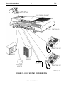
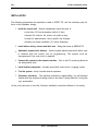
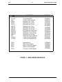
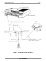
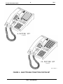
SPIRIT™ 308/616
COMMUNICATION SYSTEMS
Product Information Guide
AT&T
SERVICES DIVISION EDUCATION
MAY 1987
Select Code 999-903
Copyright © 1987 AT&T
AT&T PROPRIETARY
Use Pursuant to Company Instructions
SPIRIT™ MODEL 308/616
COMMUNICATIONS SYSTEM
Product Information Guide
AT&T Technical Training Services
Dublin, Ohio
First Edition
February 1987
Developed by
AT&T Technical Training Services
5151 Blazer Memorial Parkway
Dublin, Ohio 43017-1392
© 1987 AT&T Technical Training Services. All rights reserved. This material may not be
reproduced, stored in a retrieval system, or transmitted in whole or in part, in any form or by
any means, electronic, mechanical, photocopying, recording, or otherwise, without prior
written permission of the publisher.
Printed in the United Sates of America.
Product Information Guide
T217
TABLE OF CONTENTS
Page
OVERVIEW
1
SYSTEM CONFIGURATION
3
SPIRIT COMPETITION
5
SYSTEM DOCUMENTATION
5
GROUNDING REQUIREMENTS
6
INSTALLATION
7
SPIRIT WIRING PLAN
8
PIN ASSIGNMENTS
8
MODULAR WIRING
11
EXTERNAL PAGING EQUIPMENT
15
AUXILIARY LINES
15
EXTERNAL ALERT
17
MULTIFUNCTION STATION SETS
19
INITIAL SYSTEM TEST
20
FEATURE TONES AND RINGING
20
SPEEDCALLING
21
SPIRIT FEATURE ADMINISTRATION
23
SYSTEM MAINTENANCE
25
WARRANTY AND MAINTENANCE OPTIONS
26
AT&T – PROPRIETARY
T217
Product Information Guide
LIST OF FIGURES
FIGURE 1 - SPIRIT SYSTEM CONFIGURATION
2
FIGURE 2 - SPIRIT COMPETITION MATRIX
4
FIGURE 3 - TYPICAL SPIRIT WIRING PLAN
9
FIGURE 4 - MODULAR WIRING
10
FIGURE 5 - SBDS WIRING MATERIALS
13
FIGURE 6 - PAGING SYSTEM WIRING
14
FIGURE 7 - EXTERNAL ALERT INTERFACE
16
FIGURE 8 - 24-BUTTON MULTIFUNCTION STATION SET
18
FIGURE 9 - SYSTEM ADMINISTRATION OVERLAY MODEL
308/616
22
FIGURE 10 - HARDWARE REPLACEMENT INFORMATION
AT&T – PROPRIETARY
24
1
T217
Product Information Guide
SPIRIT™ MODEL 308/616
COMMUNICATlONS SYSTEM
OVERVIEW
The SPIRIT Model 308/616 CS is a low-cost, high-quality, high-reliability product with fixed
features and modular equipment. AT&T is the only company offering a system with a full
range of features and services in one package:
●
Call Pick-Up
●
Idle-Line Preference
●
Hands-Free Answering Intercom
●
Power Failure Operation
and many other features, providing a product without equal in the telecommunications
marketplace.
You will become thoroughly familiar with these features, so you can teach your customers to
use them when you install the system. You, the Systems Technician, are another aspect of
our edge on the competition. By taking the time to study this INFORMATION GUIDE fully, and
attending the hands-on session you are scheduled for in a few weeks, you will be able to
install and maintain the SPIRIT system and teach your customers how to use it to the best
advantage in their businesses. Your professional skills and familiarity with AT&T products
return true value for our customers’ service dollars.
AT&T — PROPRIETARY
Product Information Guide
2
T217
2500 SET
POWER FAILURE
616 EXPANSION UNIT
308 CONTROLLER
24-BUTTON SET
MUSIC
PUBLIC
ADDRESS
EXTERNAL
ALERTER
NETWORK
INTERFACE
6-BUTTON SET
217-3 2/87 1
FIGURE 1 - SPIRIT SYSTEM CONFIGURATION
AT&T – PROPRIETARY
T217
3
Product Information Guide
SYSTEM CONFIGURATION
The 308 SPIRIT CS is the smallest configuration; it has up to three CO lines and eight station
lines. Adding the optional expansion unit allows growth up to six CO lines and sixteen
stations, yielding the 308/616 Spirit system.
The model 308 control unit consists of a textured, gray plastic housing and base, enclosing
the PWB (printed wiring board) and power supply. The open grillwork on the control unit
allows proper system ventilation. The control unit is approximately 16 inches wide, 8 inches
high, and 5 inches deep. A fully equipped unit (308/616) weighs less than 10 pounds.
The system functions over 2-pair wiring and uses loop-start lines for the CO (central office)
facilities. The SPIRIT CS can be configured behind another PBX or cross-connected directly
to the CO. Stations cabled with tinsel cord, which does not have the twisted-pair structure
required to transmit data, have to be within 25 feet of the controller to function properly. If
stations are wired with twisted-pair solid-conductor cable, the working limits are 1000 feet
from the controller.
The ALERT, PAGE, LINE AUX, TELCO LINES, and STATIONS connectors are positioned and
labeled as shown in Figure 1. An RCA phono jack interfaces MOH (Music-On-Hold). The
MOH volume control can be easily adjusted by hand.
AT&T – PROPRIETARY
FEATURE
CO LINES
STATIONS
INTERCOM PATHS
SPEAKERPHONE
CONFERENCE w/DROP
SYSTEM SPEEDCALL
PERSONAL SPEEDCALL
DO NOT DISTURB
TRANSFER
HFAI/DISABLE
STATION MSG ACTIVATION
MUSIC-ON-HOLD INTERFACE
PAGING INTERFACE
PROGRAMMABLE FEATURES
IDLE LINE PREFERENCE
RINGING LINE PREFERENCE
DISTINCTIVE RINGING
TOLL RESTRICTION
0/1 restrict
allowed list
CALL PICKUP
NIGHT SERVICE
CENTRALIZED ADMIN
BRIDGING INDICATION
PWR FAILURE OPERATION
PWR FAILURE PHONES
CUSTOMER INSTALLABLE
T217
4
Product Information Guide
AT&T
SPIRIT
308/616
TIE
ULTRACOM
CKI
ITT
ARIES
401
TOSHIBA
STRATA
VI
6
16
2
yes
yes
70#
16#
yes
yes
yes
yes
yes
yes
yes
yes
yes
yes
yes
yes
yes
yes
yes
yes
yes
yes
yes
yes
8
18
0
yes
no
100#
14#
yes
yes
no
no
opt
opt
no
no
no
yes
yes
no
no
no
yes
no
no
opt
opt
opt
6
16
3
no
yes
yes
no
no
no
no
yes
yes
yes
yes
no
no
no
no
yes
no
no
no
no
no
no
no
no
6
16
2
yes
no
opt
opt
no
yes
yes
opt
opt
yes
yes
no
yes
yes
no
no
no
no
yes
yes
no
no
no
no
FIGURE 2 - SPIRIT COMPETITION MATRIX
AT&T – PROPRIETARY
5
T217
Product Information Guide
SPIRIT COMPETITION
The SPIRIT CS faces major competition for small business customers needing an electronic
key telephone system. Three companies; TIE, ITT, and TOSHIBA, are top competitors with
systems in that communications market. A feature-comparison matrix is shown on the
opposite page.
SYSTEM DOCUMENTATION
A complete set of documentation is included with this package. You will use it as part of
your study material, and it is yours to keep for future reference. SPIRIT CS control unit
documentation includes:
●
●
Administration Manual - Provides detailed information on customizing the system.
Customer Installation Instructions - Details the materials needed and instructions on
cabling and wiring.
Station set documentation includes:
●
●
●
User Manual - Details information about system features and operation of the
station sets.
Quick Reference Chart - A two page job aid outlining station set method-ofoperation.
Designation Strips - Used to designate the station and line appearance buttons on
each station set.
AT&T – PROPRIETARY
Product Information Guide
6
T217
GROUNDING REQUIREMENTS
Proper grounding is fundamental as protection against lightning/power surges, power
crosses on CO lines, and static discharge to equipment. The green-wire ground of the AC
outlet is the only ground serving the SPIRIT system. It must be connected to the building
ground. Use the following procedures to verify grounding:
1. Check the AC outlet wiring with an Ideal 61-035 tester or equivalent. The tester
comes with instructions.
2. Visually inspect the telco protection bonding to the AC power ground. Ensure that
local practices have been followed. To minimize costs, no more than 10 minutes
are allowed for this inspection. If more than 10 minutes is required, do not
complete the inspection.
3. If you find inadequate grounding/protection, and the the customer owns the
equipment or has a sales-type lease, warn him/her that lightning and power-surge
damage are excluded from warranty and contract coverage. Also tell the customer
that the risk from operating equipment without adequate protection is quite high.
4. The customer can buy a TII1428 AC power line surge protector (PEC 8310-001).
While surge protection purchase is not required when buying the system, remind
the customer that lightning and power surge damage are excluded from warranty
and contract coverage. Purchase of the surge protector is a way to reduce, but
not eliminate, the customer’s risk, If s/he is under a term plan, the surge protector
can be installed at AT&T expense, if local practice calls for it.
AT&T – PROPRIETARY
7
T217
Product Information Guide
INSTALLATION
The following procedures are required to install a SPIRIT CS, and the customer pays for
them in the installation charge:
1. Install the control unit - Special consideration should be given to:
●
Local telco CO line terminations (within 25 feet)
●
Nearest AC outlet for the control unit (within 6 feet)
●
Access for administration, future growth, and changes
●
Allowing for proper ventilation (21 inches clearance)
®
2. Install station wiring, connect and label sets - Wiring plan same as MERLIN CS.
3. Administer system-level features - Use the system planner and ensure that a copy
is retained with the control unit for programming. The system must be
reprogrammed if the control unit is replaced.
4. Connect the system to the network interface - Wire to the RJ connecting blocks at
the demarcation point.
5. Install auxiliary equipment - Includes remote bell, music source, or paging system.
6. Test the system - Verify controller and set operation.
7. Customer education - The systems technician’s responsibility; you will become
familiar with the customer training outline in the User Training Manual. lt will guide
your presentation.
At this point, take time to read the Customer Installation Instructions Manual in its entirety.
AT&T – PROPRIETARY
8
Product Information Guide
T217
SPIRIT WIRING PLAN
The SBDS (Small-Business Distribution System) wiring plan for the SPIRIT is the same plan
used for the MERLIN CS. The SPIRIT system requires two-pair wiring, but four-pair wiring is
used to facilitate migration to four-pair systems in the future. Unlike MERLIN CS control
units, SPIRIT control units ship WITHOUT 267C adapters. If these are needed, you must
provide them from your supply. Their cost is covered in the flat-rate wiring billed to the
customer. Station sets ship WITH mounting cords.
PIN ASSIGNMENTS
The modular pin assignments for the station jack on the control unit and station set are
shown below:
PIN
NUMBER
1
2
3
4
5
6
7
8
CONTROLLER JACK
8-position
No-connection
No-connection
Data/Ring
Voice Ring
Voice Tip
Data/Tip
No-connection
No-connection
PIN
NUMBER
STATION JACK
6-position
1
2
3
4
5
6
No-connection
Data/Tip
Voice Tip
Voice Ring
Data/Ring
No-connection
AT&T – PROPRIETARY
T217
Z601A
ADAPTER
Z601A
ADAPTER
Z601A
ADAPTER
9
COLOR CODES FOR 4–PR.
DIW CABLE OR DW8A-SE
CORD
COLOR CODES FOR 3–PR.
DISTRIBUTION CABLE
( H-STATION WIRE )
COLOR CODES FOR 4–PR.
DIW CABLE OR DW8A–SE
CORD
Product Information Guide
103A, 104A, 105A,
630B CONNECTING
BLOCK
103A, 104A, 105A,
630B CONNECTIN6
BLOCK
625, 725, 630B,
830B CONNECTING
BLOCK
FIGURE 3 - TYPICAL SPIRIT WIRING PLAN
AT&T – PROPRIETARY
217–8 3/87 .89
10
Product Information Guide
T217
CONTROLLER
POWER CORD
GREEN–WIRE
GROUND
AC OUTLET
ADD SURGE PROTECTOR
WHERE APPROPRIATE
NETWORK INTERFACE
JACK
RJ11, RJ14, OR RJ21
D4CH
A JACK F1ELLD INSTALLED
NEAR YOUR CONTROL
UNIT LOCATION
JUMPER CORDS
PLUGGED INTO THE
JACK FIELD AND INTO
THE CONTROL UNIT
Z122C
APPARATUS BOXES
W/Z600 SERIES ADAPTERS
CABLE EXTENDING FROM
THE JACK FIELD TO EACH
TELEPHONE LOCATION
DW8A CORD
4–PR DIW OR
REUSED 25–PR CABLE
A MODULAR JACK AT THE END OF
EACH CABLE (TELEPHONES WILL BE
PLUGGED IN LATER)
D4BU CORD
103A CONNECTOR
BLOCK
FIGURE 4 - MODULAR WIRING
AT&T – PROPRIETARY
D4BU CORD
217–7 3/87 1
11
T217
Product Information Guide
MODULAR WIRING
The method of connection depends on the building wiring termination. Use the following
station and distribution wire:
●
Tinsel Cord - A 2-pair double-ended modular cord used primarily for sets.
●
D-Station Wire - A 22-gauge, two-pair distribution wire.
●
H-Station Wire - A 24-gauge, three-pair distribution wire.
●
D-Inside Wire - DIW is a 24-gauge, multiple-paired cable.
When reusing existing building wiring, adapters can be used but will require a Z122C
apparatus box.
AT&T – PROPRIETARY
Product Information Guide
12
NOTES
T217
T217
13
Product Information Guide
ITEM
DESCRIPTION
COMCODE
103A-50
258A
D2R-29
D2R-29
D2R-29
D4BU-29
D4BU-29
D4BU-29
D4CE-50
DW8A-SE
DW8A-SE
D8W-87
DIW
D-Station
H-Station
Connecting Block
25-pair to Mod. Adapter
Mounting Cord 7 foot
Mounting Cord 14 foot
Mounting Cord 25 foot
Mounting Cord 7 foot
Mounting Cord 14 foot
Mounting Cord 25 foot
Set Extension Cord 50 foot
Distribution Cord 100 foot
Distribution Cord 200 feet
Mounting Cord 2.5 feet
Inside Wire Spool 1000 feet
2-Pair wire Ivory 600 feet
3-Pair wire Gray 600 feet
103104220
102605136
103732541
103732566
103732582
102479904
102479896
102479888
103951570
103895694
103736138
104160148
403101140
401836580
401836598
Z122C
Z600A
Z601A
Z602A
Z610A
Apparatus Box
Mod to Mod Adapter
Mod to Cut-down Adapter
Mod to 25-pair Adapter
Cut-down to Mod Adapter
103980843
103946646
103946653
103946661
103950556
FIGURE 5 - SBDS WIRING MATERIALS
AT&T – PROPRIETARY
T217
14
Product Information Guide
CONTROLLER
PAGE
SIX–POSITION
MODULAR CORD
WIRING LABEL
25' RCA–ENDED
CORD
PAGE INPUT
Y CONNECTOR
MUSIC IN
MALE–MALE
RCA–ENDED
CORD
POWERMATE
25' RCA-ENDED
CORD
TUNER
Y CONNECTOR
SPEAKER
217-9 3/87 1
FIGURE 6 - PAGING SYSTEM WIRING
AT&T – PROPRIETARY
15
T217
Product Information Guide
EXTERNAL PAGING EQUIPMENT
The PagePac 1 (for systems with optional public address system) is a loudspeaker paging
system with 1-way transmission. Answerback paging is not supported by the SPIRIT CS.
Typical hardware provided with the system is a PowerMate amplifier, speakers and wiring.
The amplifier connects to the control unit via a 4-conductor, 6-position modular cord. We
recommend a direct connection from the control unit whenever possible. The speakers
connect through 2-conductor, RCA-jack ended cords. The PowerMate is supplied with six
24-foot cords, “Y” adapters and three speakers.
AUXILIARY LINES
There are two LINE AUX jacks on the 308 controller, and one on the 616 expansion unit. The
jacks bridge the CO lines at the control unit, and are the connection to an outside line
during a power failure. A standard (tip/ring) 2500 set or equivalent must be used for
power-failure telephones. In the event of a commercial power failure, programmed system
information will be retained in memory indefinitely.
The jacks are also useful as dedicated lines for answering machines, facsimile machines,
and modems. If an answering machine is cabled to LINE AUX jack 1 on the 308 and is inuse (off-hook), the incoming line 1 button appearance cannot be accessed at the station set.
LINE AUX jack 2 on the 308 control unit bridges line 2, and the LINE AUX jack on the 616
expansion unit bridges incoming line 4.
AT&T – PROPRIETARY
T217
16
Product Information Guide
616 EXPANSION UNIT
308 CONTROLLER
BELL
7–FOOT MODULAR CORD ( 4–WIRE )
DCI–48–48
6–POSITION
OUTPUT JACK
6–POSITION
INPUT JACK
25–FOOT MODULAR CORD ( 4-WIRE )
SUPPLIED WITH ALERTS
6–FOOT POWER CORD
AC OUTLET
217-5 3/87 1
FIGURE 7 - EXTERNAL ALERT INTERFACE
AT&T – PROPRIETARY
T217
17
Product Information Guide
EXTERNAL ALERT
The Wheelock DCI-48-48 is an interface unit for powering 48 V DC telephone bells, chimes,
horns, strobes, and other external alerts for electronic key systems. The 6-position modular
INPUT connects to the control unit ALERT jack while the 6-position OUTPUT connects to the
alert device.
The DCI-48-48 should be wall-mounted within seven feet of the control unit and within six
feet of the AC outlet. This unit should use the same AC duplex outlet as the control unit, to
ensure that the ground wire is common to both units.
AT&T – PROPRIETARY
T217
18
Product Information Guide
6–BUTTON SET
CS6501
24–BUTTON SET
CS6502
217-2 2/87 1
FIGURE 8 - 24-BUTTON MULTIFUNCTION STATION SET
AT&T – PROPRIETARY
19
T217
Product Information Guide
MULTIFUNCTION STATION SETS
The first six buttons on the 6-button and the 24-button sets correspond to the control unit
TELCO LINE jacks.
Buttons labeled 10 through 25 correspond to the sixteen control unit STATION jacks. These
buttons are used for autodialing the 2-digit extension numbers on the 24-button set. The
numbers 7, 8, and 9 are omitted, since they have no meaning in the system.
Buttons 26 and 27 of the 24-button set are user-programmable buttons for Loudspeaker
Paging, Paging to all extensions, or for Manual Signaling others in the system. These two
buttons cannot be used for speedcalling.
Station set volume control adjustments affect three modes:
1.
Speakerphone - can be changed when the speaker is ON.
2.
Ringer - can be changed when the set is ringing, or when the set is on-hook and
the speaker is OFF.
3.
Receiver (handset) - can be changed when the set is off-hook and the speaker is
OFF. (The K2N2 handsets are clearly marked and are usable ONLY on the SPIRIT
station sets).
The system software remembers the last volume level set for each mode.
Refer to the SPIRIT User Manual, Pages 2 and 3, for a complete description of the control
keys and LEDs on the station sets.
AT&T – PROPRIETARY
20
Product Information Guide
T217
INITIAL SYSTEM TEST
Power is applied to the control unit through a line cord plugged into a standard 110 V AC
outlet. A lighted green LED, visible in the upper left corner of the control unit, serves as the
POWER ON indicator. The control unit software checks all its common hardware
immediately after the powerup. At this point, test the CO lines and stations at the controller.
FEATURE TONES AND RINGING
Refer to User’s Manual, Page 4, for information on distinctive ringing and the meaning of
various LED patterns.
Seven distinctive tones interact with system features:
1.
Intercom dial
2.
Central office dial
3.
Splash
4.
Busy
5.
Intercept or error
6.
Confirmation
7.
Manual signaling
Distinctive ringing allows you to identify:
1.
One ring as an inside or intercom call.
2.
Two rings as a call from outside the system.
3.
One short and one long ring as call transfer.
4.
Three rings as line reserve or returned transfer.
5.
One short, low volumn ring as incoming call when station is busy.
AT&T – PROPRIETARY
21
T217
Product Information Guide
SPEEDCALLlNG
All speedcall numbers are assigned a 2-digit dial access code. There are two kinds of
speedcall numbers:
1. Personal numbers are assigned by individual station users, and are accessed with
digits 10 through 25. Each user may store 16 speedcall numbers.
2. System numbers are stored in the system memory and are accessed by all users. A
maximum of 70 system numbers can be assigned; 50 unrestricted and 20 restricted.
Refer to the System Administration Manual, Pages 24 and 25, for storing and erasing
speedcall numbers.
AT&T – PROPRIETARY
Product Information Guide
22
T217
ADMINISTRATION
SWITCH
POWER
INDICATOR
OPEN
GRILLWORK
616 EXPANSION HEADER
308 CONTROL UNIT
616 CONTROL UNIT
217-4 3/2 1
FIGURE 9 - SYSTEM ADMINISTRATION OVERLAY MODEL
308/616
AT&T – PROPRIETARY
23
T217
Product Information Guide
SPIRIT FEATURE ADMINISTRATION
The system will function with the assigned default values when power is applied Changes
may be administered to system features affecting each CO line appearance or each station
set. If choices for programmable features are administered, each feature should be tested
to assure proper operation.
SPIRIT CS administration may be carried out from either a 6-button or a 24-button set.
Three important steps are required for entering the administration mode:
1. The control unit ADMIN switch must be ON.
2. The administration overlay must be in place on station 10.
3. The set must be plugged into control unit jack 10 (call processing is interrupted only
at station 10).
Take time now to read Pages 4 through 17 of the Administration Manual. Pay special
attention to the flowchart on Page 9; it is an excellent 1-page reference when you are
administering a system. You will practice administration when you attend the class.
AT&T – PROPRIETARY
Product Information Guide
24
T217
MANUFACTURER’S
DESCRIPTION
COMCODE
PEC CODE
308 CONTROLLER
CNTRL-CS308A1
103985396
6030-308
616 EXPANSION UNIT
CNTRL-CS616A1
103985404
60301
6-BUTTON SET
SET TEL-CS6501C01A-215
104372339
3130-006
24-BUTTON SET
SET TEL-CS6502C01A-215
104372347
3130-024
K2N2-215 HANDSET
103985701
6' HANDCORD
H4DU-215
104211305
12' HANDCORD
H4DU-215
104211339
EXTERNAL ALERT INTFC
405291568
COMMON
DESCRIPTION
HANDSET
WHEELOCK DCI-48-48
60314
FIGURE 10 - HARDWARE REPLACEMENT INFORMATION
AT&T – PROPRIETARY
T217
25
Product Information Guide
SYSTEM MAINTENANCE
Read Pages 17 and 18 of the Customer Installation Instructions. You will have a hands-on
exercise to try these tests when you attend class.
CAUTION: Initiating system self-test interrupts call-processing.
Control unit self-tests are made at connector location 10 from the ADMIN mode.
Software changes/corrections cannot be made in the field: all software-related problems
are cleared by hardware replacement.
The programmable memory in the SPIRIT system is NOT replaceable. Therefore, replacement
of the control unit requires readministration of the system. A copy of the customer SYSTEM
PLANNER form (from the Administration Manual) MUST be retained at the control unit.
AT&T – PROPRIETARY
26
Product Information Guide
T217
WARRANTY AND MAINTENANCE OPTIONS
Maintenance options include on-premises service with business-day and 24-hour choices,
with depot service as a secondary choice. Maintenance contracts cover the entire system,
not just parts of it. During the ONE-YEAR warranty period or the term plan, business-day
coverage is included in the purchase or term plan price, and 24-hour coverage, on-premises
service is offered as an option. Post-warranty maintenance options include on-premises
service with business-day, 24-hour coverage or depot service.
Station sets are shipped from the factory with information stickers affixed to each set. For
tracking, note the installation date, and if a defective set is returned for repair, enter that
date on the sticker.
DATE INST:
DATE REM:
Attach the AT&T Information Hotline sticker to the control unit where it is visible, to provide
important information to the customer.
EXAMPLE – STICKER
AT&T
HOTLINE - 1-800-628-2888
for Repair Information or Operation
and Programming Assistance
BUSINESS SALES OFFICE – 1–800–247–7000
for Equipment Addition or Changes
AT&T – PROPRIETARY