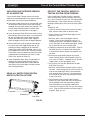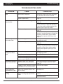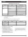
1
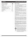
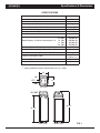
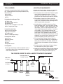
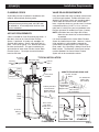
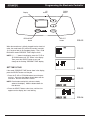
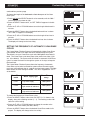
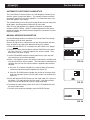
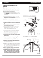
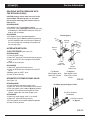
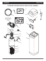
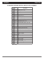
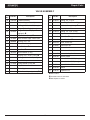
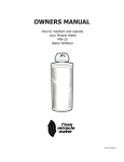
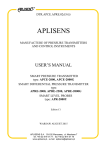
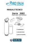
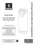
OWNER’S MANUAL
How to install, operate and maintain your
EcoWater Systems
Central Water Filtration System
Model ECWS
System tested and certified by NSF International
against NSF/ANSI Standard 42.
See performance data sheet for details.
Printed on recycled paper
EcoWater Systems LLC
P.O. Box 64420, St. Paul MN 55164-0420
PRINTED IN U.S.A.
Part No. 7308784 (Rev. D 9/3/09)
ECOWATER
Table of Contents & Safety Guides
S Y S T E M S
TABLE OF CONTENTS
SAFETY GUIDES
Page
Specifications & Dimensions . . . . . . . . . . . . . . . . . . . 3
Installation Requirements . . . . . . . . . . . . . . . . . . . . 4-5
Installation . . . . . . . . . . . . . . . . . . . . . . . . . . . . . . . 6-9
How a Central Water Filtration System Works . . . . 10
Start Up Procedure . . . . . . . . . . . . . . . . . . . . . . . . . 11
Programming the Electronic Controller . . . . . . . . . . 12
Customizing Features / Options . . . . . . . . . . . . . 13-15
Care of the Central Water Filtration System . . . . . . 16
Troubleshooting . . . . . . . . . . . . . . . . . . . . . . . . . 17-18
Service Information . . . . . . . . . . . . . . . . . . . . . . 19-22
Repair Parts . . . . . . . . . . . . . . . . . . . . . . . . . . . . 24-27
Warranty . . . . . . . . . . . . . . . . . . . . . . . . . . . . . . . . . 28
Follow the installation instructions carefully. Failure to
install the EcoWater Systems Central Water Filtration
System properly voids the warranty.
Before you begin installation, read this entire manual.
Then, obtain all the materials and tools you will need to
make the installation.
Check local plumbing and electrical codes.
installation must conform to them.
The
Use only lead-free solder and flux for all sweat-solder
connections, as required by state and federal codes.
Use care when handling the EcoWater Systems Central
Water Filter. Do not turn upside down, drop, or set on
sharp protrusions.
Do not locate the EcoWater Systems Central Water Filter
where freezing temperatures occur. Do not attempt to
treat water over 120°F. Freezing, or hot water damage
voids the warranty.
Avoid installing in direct sunlight. Excessive sun heat
may cause distortion or other damage to non-metallic
parts.
The EcoWater Systems Central Water Filter requires a
minimum water pressure of 30 psi at the inlet. Maximum
allowable inlet water pressure is 125 psi. If daytime
pressure is over 80 psi, nighttime pressure may exceed
the maximum. Use a pressure reducing valve if necessary (Adding a pressure reducing valve may reduce the
flow).
The EcoWater Systems Central Water Filter works on
24 volt, 60 Hz electrical power only. Be sure to use the
included transformer and plug it into a nominal 120V,
60 Hz household outlet that is in a dry location only,
grounded and properly protected by an over current
device such as a circuit breaker or fuse. If transformer is
replaced, use only the authorized service, Class II, 24V,
10 VA transformer.
This system is not intended to be used for treating water
that is microbiologically unsafe or of unknown quality
without adequate disinfection before or after the system.
European Directive 2002/96/EC requires all
electrical and electronic equipment to be disposed of according to Waste Electrical and
Electronic Equipment (WEEE) requirements.
This directive or similar laws are in place
nationally and can vary from region to region.
Please refer to your state and local laws for
proper disposal of the equipment.
2
ECOWATER
Specifications & Dimensions
S Y S T E M S
SPECIFICATIONS
Model ECWS
Model Code
Nominal Mineral Tank Size
Rated Service Flow Rate
Pressure Drop at Rated Service Flow
Pressure Drop at 12 gpm
Water Pressure Limits (minimum / maximum)
Water Temperature Limits (minimum / maximum)
0.50
0.75
Rated Capacity at Chlorine Concentration** of: 1.0
1.5
2.0
EC
8” dia. x 35”
6.0 gpm
4 psig*
9 psig*
30 - 125 psi
40 - 120 °F
ppm
ppm
ppm
ppm
ppm
2,780,000
1,850,000
1,390,000
925,000
695,000
Backwash Time, default (length is adjustable)
Fast Rinse Time, default (length is adjustable)
Drain Flow Rate (during Backwash & Fast Rinse)
gal.*
gal.*
gal.*
gal.*
gal.*
2 minutes
1 minute
3.0 gpm
12 pounds
(0.40 cu. ft.)
Amount of Activated Carbon
Amount of Filter Sand
Amount of Gravel
5 pounds
6 pounds
* From independent laboratory test data.
** Typical residential chlorine concentration is 0.5 to 1.0 ppm.
14"
14”
IN
IN
3-3/4"
3-3/4”
14”
14"
OUT
OUT
TOP VIEW
TOP
VIEW
IN IN
- OUT
- OUT
44-3/4”
44-3/4"
39-1/4”
39-1/4"
SIDEVIEW
VIEW
SIDE
FRONT VIEW
FRONT
VIEW
3
FIG. 1
ECOWATER
Installation Requirements
S Y S T E M S
TOOLS NEEDED
LOCATION REQUIREMENTS
Assemble the required tools before starting installation. Read and follow instructions provided with any
tools listed here.
Consider the following when selecting an installation
location for the Central Water Filtration System.
Do not operate the Central Water Filtration System
where freezing temperatures occur. Do not
attempt to treat water over 120ºF. Freezing temperatures or hot water damage voids the warranty.
Screwdriver
Tape measure
Pliers
To condition all water in the home, install the
Central Water Filtration System close to the water
supply inlet, and before all other plumbing connections, except outside water pipes.
If using Soldered Copper Pipe
Tubing cutter
Lead-free solder and flux
Propane torch
Emery cloth, sandpaper or steel wool
Misc. copper pipe fittings
If using CPVC Plastic
A nearby drain is needed to carry away Clean
Rinse discharge water. Use a floor drain, laundry
tub, sump, standpipe, or other options (check your
local codes). See "Air Gap Requirements" and
"Valve Drain Requirements" sections. If a drain is
not available, it is still possible to operate the
Central Water Filtration System in a manual Clean
Rinse mode. See “Operating in Manual Clean
Rinse Mode.” The automatic Clean Rinse must be
disabled if the Central Water Filtration System will
not be connected to a drain (See Page 15).
Pipe cutter
Solvent cement
Hacksaw
Primer
Adjustable wrench
The Central Water Filtration System works on
24 volt, 60 Hz electrical power only, supplied by a
direct plug-in transformer (included). Provide an
electrical outlet in accordance with NEC and local
codes.
If using Other
Do not install the Central Water Filtration System
on a hot water line (See Figure 2 below).
Other pipe and fittings suitable for potable water as
required by piping system manufacturer and local
codes and/or ordinances.
Install the Central Water Filtration System between
the home’s incoming water supply and the water
softener, if one is being used (See Figure 2).
If using Threaded Pipe
Pipe cutter or hacksaw
Pipe joint compound
Threading tool
Misc. threaded pipe fittings
THE PROPER ORDER TO INSTALL WATER TREATMENT EQUIPMENT
Untreated Water to
Outside Faucets
Cold Water
to House
Hot Water
to House
City Water Supply
Optional
Sediment
Filter
Water
Heater
Water
Softener
Pressure
Tank
OR
Well Water Supply
Central
Water
Filtration
System
Well
Pump
FIG. 2
4
ECOWATER
Installation Requirements
S Y S T E M S
PLUMBING CODES
VALVE DRAIN REQUIREMENTS
All plumbing must be completed in accordance with
national, state and local plumbing codes.
Using the flexible drain hose (included), measure and
cut to the length needed. Flexible drain hose is not
allowed in all localities (check your plumbing codes).
If local codes do not allow use of a flexible drain
hose, a rigid valve drain run must be used. Purchase
a compression fitting (1/2 NPT x 1/2 in. minimum
tube) and 1/2" tubing from your local hardware store.
Plumb a rigid drain as needed (see Figure 3, below).
In the state of Massachusetts: The Commonwealth
of Massachusetts plumbing code 248-CMR shall
be adhered to. A licensed plumber shall be used
for this installation.
NOTE: Avoid drain hose runs longer that 30 feet.
Make the valve drain line as short and direct
as possible.
AIR GAP REQUIREMENTS
A drain is needed for Clean Rinse discharge water. A
floor drain, close to the Central Water Filtration
System, is preferred. A laundry tub, standpipe, etc.
are other drain options. Secure valve drain hose in
place. Leave an air gap of 1-1/2” between the end of
the hose and the drain. This gap is needed to prevent backflow of sewer water into the Central Water
Filtration System . Do not put the end of the drain
hose into the drain.
To Outside
Faucets
Incoming
Unfiltered
Water
Drain
Fitting
It is recommended that the Central Water Filtration
System be installed near a drain. However, if a drain
is not available, it is still possible to operate the
Central Water Filtration System in a manual Clean
Rinse mode. See “Operating in Manual Clean Rinse
Mode” section. The automatic Clean Rinse function
must be disabled if the Central Water Filtration
System will not be connected to a drain.
TYPICAL INSTALLATION
Main Water Pipe
IN
OUT
Filtered
Water
120V, 60
Hz Outlet
SUBSTITUTING RIGID DRAIN LINE
To Electronic
Controller
Hose
Clamp
1/2 NPT Threads
Barbs
1/2” Outside Dia.
Copper Tube
(not included)
Clip
To drain point other
than floor drain.
Support tubing in
place as needed.
Cut barbs from
drain fitting (pull
clip to remove
fitting from valve) Comp Fitting. 1/2
NPT x 1/2” O.D.
Tube (not included)
Valve
Drain
Hose
Direct end of
hose down
toward center of
floor drain
Tie or wire
tubing in
place
1-1/2”
air gap
1-1/2”
air gap
1-1/2”
air gap
LAUNDRY TUB
FLOOR DRAIN
5
STANDPIPE
FIG. 3
ECOWATER
Installation
S Y S T E M S
1. UNPACKING
Copper
Tubes (2)
Clips (4)
EcoWater Systems Central Water Filtration System is
shipped from the factory in one master carton. The
carton also includes a bag of small parts needed to
assemble and install the unit, plus this manual.
O-Rings
(4)
Thoroughly check the Central Water Filtration System
for possible shipping damage and parts loss. Also
inspect and note any damage to the shipping carton.
Notify the transportation company if damage is present. EcoWater Systems is not responsible for in-transit damages.
Valve
Remove and discard (RECYCLE) all packing materials. We suggest you keep the small parts in the
bag(s) until you are ready to use them.
Bypass
Valve
2. INSTALL BYPASS VALVE and/or COPPER TUBES
FIG. 4
NOTE: Before installing the bypass valve or copper
tube into the valve’s OUTLET, make sure that the turbine and support are firmly in place, as shown in
Figure 6.
Clips (2)
a. If installing an EcoWater Systems Bypass Valve,
put lubricated o-ring seals onto both bypass valve
ports (See Figure 4). Carefully slide the bypass valve
into the filter valve and install the "C" clips.
Copper
Tubes (2)
Valve
O-Rings (2)
b. Slide a lubricated o-ring seal onto each of the copper tubes. Carefully insert the copper tubes into the
bypass valve (See Figure 4), or into the filter valve
(Figure 5). Then install the “C'' clips.
NOTE: For lubrication, use silicone grease approved
for potable water supplies.
3. TURN OFF WATER SUPPLY
FIG. 5
a. Close the main water supply valve near the well
pump or water meter.
b. Shut off the electric or fuel supply to the water
heater.
c. Open high and low faucets to drain all water from
the house pipes.
Turbine
Support
Turbine
6
Valve
Outlet
FIG. 6
ECOWATER
Installation
S Y S T E M S
4. INSTALLING THREE-VALVE BYPASS
3 VALVE BYPASS
If installing a 3-valve bypass system, plumb as needed using Figure 7 as a guide. When installing sweat
copper, be sure to use lead-free solder and flux,
required by federal and state codes. Use pipe joint
compound on outside pipe threads.
5. ASSEMBLE INLET & OUTLET PLUMBING
Measure, cut, and loosely assemble pipe and fittings
from the main water pipe (or from the bypass valves
installed in Step 4), to the inlet and outlet copper
tubes, installed in Step 2b.
Be sure incoming water supply pipe goes to the
valve inlet side. Trace the water flow direction to be
sure.
Central Water Filtration
System OUTLET
Central Water Filtration
System INLET
6. CONNECT INLET & OUTLET PLUMBING
FIG. 7
a. SOLDERED COPPER
(1) Thoroughly clean and flux all joints.
(2) Pull the plastic “C'' clips and remove the inlet and
outlet tubes from the valve. Remove o-rings from the
tubes. DO NOT solder with tubes in the valve.
Soldering heat will damage the valve.
CROSS OVER
In what direction does the water flow?
NOTE: If installing a ground as shown in Figure 9,
place ground clamps on copper tubes before soldering (See Step 6a).
Be sure to plan piping so water flow is to the
Central Water Filtration System valve INLET.
Plan a crossover if flow is from left to right.
(3) Make all solder connections. Be sure to keep fittings fully together, and pipes square and straight.
Main
b. THREADED PIPE
(1) Apply pipe joint compound to all outside pipe
threads.
Wate
r
Pipe
(2) Tighten all threaded joints.
(3) If soldering to the inlet and outlet tubes, observe
Step 6a above.
c. CPVC PLASTIC PIPE
(1) Clean, prime and cement all joints, following the
manufacturer's instructions supplied with the plastic
pipe and fittings.
Treated
Water from
Valve
OUTLET
(2) If soldering to the inlet and outlet tubes, observe
Step 6a above.
To Central Water
Filtration System
7
Untreated
Water to
Valve
INLET
FIG. 8
ECOWATER
Installation
S Y S T E M S
7. COLD WATER PIPE GROUNDING
The house cold water pipe (metal only) is often used
as a ground for the house electrical system. The 3valve bypass type of installation, shown in Figure 7,
will maintain ground continuity. If you use the plastic
bypass, continuity is broken. To restore the ground,
do either step 7a or 7b following.
Ground
Clamp
a. Use the ground clamp kit (included) to make a
jumper across the inlet and outlet copper tubes (See
Figure 9).
FIG. 9
b. Install a #4 copper wire across the removed section of main water pipe, securely clamping at both
ends (See Figure 10) – parts not included.
Ground
Wire
8. INSTALL VALVE DRAIN HOSE
NOTE: See valve drain options on Page 5.
a. Connect a length of 1/2" I.D. hose (check codes) to
the valve drain elbow, on the controller. Use a hose
clamp to hold the hose in place. Route the hose out
through the notch in the back of the top cover.
Clamp (2)
b. Avoid drain hose runs longer that 30 feet. Make
the valve drain line as short and direct as possible.
FIG. 10
c. Run the hose to the floor drain, and as typically
shown in Figure 3, tie or wire the end to a brick or
other heavy object. This will prevent “whipping” during recharges. Be sure to provide a 1-1/2" minimum
air gap, to prevent possible sewer water backup (See
“Air Gap Requirements” section).
Drain Line
Connection
Pull handle
OUT for normal
operation
Push handle IN
for BYPASS
FIG. 11
8
ECOWATER
Installation
S Y S T E M S
9. PRESSURE TESTING FOR LEAKS
10. CONNECT TRANSFORMER
To prevent excessive air pressure in the EcoWater
Central Water Filtration System and plumbing
system, do the following steps EXACTLY in order:
a. During installation, the Central Water Filtration
System wiring may be moved or jostled from place.
Check to be sure all leadwire connectors are secure
on the back of the electronic control board (See
Figure 31 on Page 21) and be sure all wiring is away
from the valve gear and motor area, which rotates
during Clean Rinse cycles.
a. Fully open two or more filtered cold water faucets
nearby the EcoWater Systems filter.
b. Place the bypass valve(s) in bypass position (See
Figures 32 & 33 on Page 22).
b. Plug the transformer into a continuously “live,”
grounded, 120V, 60Hz house electrical outlet, in a dry
location and approved by local codes. The unit
works on 24V only. Do not connect without the
transformer.
c. Fully open the main water supply valve. Watch
until the flow from the opened faucets becomes
steady, with no spurting or air bubbles.
d. EXACTLY as follows, place bypass valve(s) into
service:
(1) SINGLE BYPASS VALVE: Slowly move the
valve stem toward service position, pausing several times to allow the unit to pressurize slowly.
11. SET PRESENT TIME ON THE ELECTRONIC CONTROLLER
In the display, the words “PRESENT TIME” appear
and 12:00 PM begins to flash. Set the clock according to the “Set Time of Day” section on Page 12.
(2) 3-VALVE BYPASS: Fully close the bypass valve
and open the outlet valve. Slowly open the inlet
valve, pausing several times to allow the unit to
pressurize slowly.
12. RUN START UP PROCEDURE
e. After about three minutes, open a hot water faucet
for one minute, or until all air is expelled, then close.
Run the Start Up Procedure, as detailed on Page 11,
to purge the system of fine carbon particles.
f. Close all cold water faucets and check your plumbing work for leaks.
13. RESTART THE WATER HEATER
IMPORTANT: Start up procedure must be run prior to
using any filtered water. Follow the instructions at
right and on Page 11.
Once the Start Up Procedure has been completed,
turn on the electric or fuel supply to the water heater,
and light the pilot, if applies.
NOTE: The water heater is filled with unfiltered water
and, as hot water is used, it refills with filtered water.
In a few days, the hot water will be fully filtered. To
have fully filtered hot water immediately, wait until the
start up procedure (Step 12) is complete, then drain
the water heater until water runs cold.
9
ECOWATER
S Y S T E M S
How a Central Water Filtration System Works
NORMAL OPERATION
APPLICATIONS FOR A CENTRAL WATER
FILTRATION SYSTEM
During normal operation water enters the Central
Water Filtration System and flows through several filtration processes where tastes, odors and sediment
are reduced.
Do not use the Central Water Filtration System with
water that is microbiologically unsafe or of unknown
quality without adequate disinfection before or after
the system.
The Central Water Filtration System may not be an
effective treatment method for water sources with a
hydrogen sulfide problem (rotten egg odor or taste).
CLEAN RINSE CYCLE
A Clean Rinse cycle will automatically be initiated
based on how many gallons of water have been filtered through the system (or after 14 days if no water
has passed through the system in that time). The
Clean Rinse cycle lifts and expands the media bed to
rejuvenate the media and then repacks the bed for
continued use. During the Clean Rinse cycle, dirt,
sediment, etc. are flushed from the Central Water
Filtration System down the drain.
The Central Water Filtration System will not remove
iron and is not intended to replace iron treatment
equipment.
Although the Central Water Filtration System has
sediment filter capabilities, additional sediment filtration may be needed in problem water applications.
10
ECOWATER
Start Up Procedure
S Y S T E M S
IMPORTANT:
Run the start up cycle immediately after
completing installation, before using any
water in the home.
During the start up cycle:
Throughout the start up cycle you will hear the valve
changing position and notice the flow of water to drain
starting and stopping. The start up cycle will take
approximately 20 minutes. Avoid using water during
this time. Do not set the time of day or press other
buttons during the start up cycle, as this will interrupt
the start up cycle. Do not unplug the transformer during the start up cycle. If the start up cycle is interrupted, it should be initiated again and allowed to run to
completion.
The filtration media in this Central Water Filtration
System contains a small number of harmless activated
carbon particles generated during shipping that are
small enough to exit the system with water flow. It is
normal for these particles to cause a temporary discoloration of the water coming out of the system. To
avoid discolored water at your home’s faucets the system’s start up cycle should be initiated to rinse the particles and any discolored water down the drain.
If the Central Water Filtration System is used without
first running the start up cycle, you will notice that the
water will temporarily have a gray color until the particles have exited the system.
After the start up cycle:
Once the start up procedure completes successfully, it
cannot be initiated a second time. The Central Water
Filtration System will automatically return to the normal
operation position. Once the start up cycle has run, a
faucet in the home should be opened and water
allowed to run for 10 minutes at the system’s rated
flow. If, after running the start up cycle, the water still
appears discolored, manually run Clean Rinse cycles
(See Page 13) until the water is clear.
To Initiate the start up cycle:
1. Make sure the drain hose is attached to the Central
Water Filtration System and the other end is
secured over a drain (see Figure 3 on Page 5).
2. Make sure bypass valve is in the “service” (open or
filtered water) position and the home’s water supply
is turned on.
If the time of day was not set before the start up cycle,
set it now (See Page 12).
3. Press and hold the RECHARGE button to initiate
the start up cycle. The button can be released
when you hear the valve changing position and
“RECHARGE NOW” flashes in the display.
Check the new plumbing connections and joints once
more for leaks.
11
ECOWATER
Programming the Electronic Controller
S Y S T E M S
Display
UP
button
RECHARGE
button
DOWN
button
SELECT
button
FIG. 12
When the transformer is initially plugged into the electrical
outlet, the model code (EC) and a test number (example:
J1.4), begin to flash in the faceplate display. Then, 12:00
PM and the words “PRESENT TIME" begin to flash.
NOTE: If “- - - -” shows in the display, press the UP or
DOWN button until “EC” shows in the display.
Then, press the SELECT button to set, and
change to the flashing “PRESENT TIME" display.
SET TIME OF DAY
FIG. 13
If the words “PRESENT TIME" do not show in the display,
press the SELECT button until they do.
1. Press the UP or DOWN buttons to set the present time. Up moves the display ahead; down sets the
time back. Be sure AM or PM is correct.
NOTE: Press buttons and quickly release to slowly
advance the display. Hold the buttons down for
fast advance.
2. Press the SELECT button a few times, until the time
appears on the display, but is not flashing.
FIG. 14
12
ECOWATER
Customizing Features / Options
S Y S T E M S
START A CLEAN RINSE CYCLE
To manually start a Clean Rinse cycle, press and hold the RECHARGE button for a few seconds, until “RECHARGE NOW” flashes in the display. This
Clean Rinse cycle takes 3 minutes (unless the factory settings for backwash
and fast rinse times have been changed, as shown below).
FIG. 15
SET CLEAN RINSE START TIME
By default the Central Water Filtration System will Clean Rinse at 1:00 a.m.
The system will not filter water during the Clean Rinse cycle. It is recommended that the Clean Rinse start time be set for when water is not likely to
be used in the household.
NOTE: If you also have a water softener, set the Central Water Filtration
System’s Clean Rinse time for either one hour before or two hours
after the water softener’s scheduled regeneration time.
To change the Clean Rinse start time:
1. Press the SELECT button a few times until “RECHARGE TIME” is shown
in the display.
2. Press the UP or DOWN buttons to set the Clean Rinse time in 1
hour increments. Be sure AM or PM is correct.
FIG. 16
3. When the desired Clean Rinse time is displayed, press the SELECT button a few times, until the time appears in the display, but is not flashing.
12 OR 24 HOUR CLOCK
The electronic controller has been factory preset to display a 12 hour clock
(AM / PM). If you prefer, you may change this to display a 24 hour clock.
1. Press and hold the SELECT button for a few seconds, until the “000--”
screen appears, as shown at right.
2. Press the SELECT button once and “12 hr" will flash in the display.
3. Use the
UP button to change to a 24 hour clock display.
4. Press the SELECT button several times to advance through the remaining screens and return to the normal operation (time of day) display.
5. To change back to a 12 hour clock, follow Steps 1 through 4, above,
except use the DOWN button in Step 3.
SET LENGTH OF CLEAN RINSE
By default the Central Water Filtration System’s Clean Rinse cycle will consist of a 2 minute backwash followed by a 1 minute fast rinse. This should
be sufficient for most applications.
Increasing the length of Clean Rinse time will increase the amount of water
flushed to drain during each Clean Rinse cycle. Increasing the length of
Clean Rinse should only be done in cases of very high amounts of sediment, or other water issues.
continued on next page
13
FIG. 17
ECOWATER
Customizing Features / Options
S Y S T E M S
continued from previous page
To change the length of the backwash or fast rinse parts of the Clean
Rinse cycle:
1. Press and hold the SELECT button for a few seconds, until the “000--”
screen appears, as shown at right.
2. Press the SELECT button twice, so “SET TIME bA” appears in the display.
3. Press the
minutes.
UP or DOWN buttons to set the length of backwash in
4. Press the SELECT button when the desired backwash time is shown.
“SET TIME Fr” appears in the display.
5. Press the
minutes.
UP or DOWN buttons to set the length of fast rinse in
6. Press the SELECT button when the desired fast rinse time is shown.
The display will change to the time of day.
SETTING THE FREQUENCY OF AUTOMATIC CLEAN RINSE
CYCLES
FIG. 18
The Central Water Filtration System will automatically initiate Clean Rinse
cycles based on how much water has been filtered through the system.
The default is to run a Clean Rinse cycle after 3000 gallons have been filtered. The Clean Rinse cycle takes place at the preset time of day (1:00
a.m. is the default). The system also will initiate an automatic Clean Rinse
cycle if no water has been run through the system in 14 days, to keep the
filter bed fresh.
The Central Water Filtration System allows the frequency of automatic
Clean Rinse cycles to be increased for systems where the water supply
may have more sediment than in a typical municipal water supply. The table
below shows the three settings available. The unit is shipped with “CLn 1”
as the default.
Clean Rinse
mode
Water supply type
Clean Rinses
every
CLn 1
City water supply
3000 gallons
CLn 2
Well water with a
light amount of sediment
2000 gallons
CLn 3
Well water with a
high amount of sediment
1000 gallons
To change the frequency of Clean Rinse cycles:
1. Press the SELECT button a few times until “SET CLn” is shown in the
display, along with a flashing number (1 - 3). The flashing number indicates the current setting.
2. Press the UP or DOWN buttons to change the number to the
desired Clean Rinse mode (see table, above).
3. Press the SELECT button when the desired Clean Rinse mode is displayed. The display will change to the time of day.
14
FIG. 19
ECOWATER
Customizing Features / Options
S Y S T E M S
OPERATING IN MANUAL CLEAN RINSE MODE
Clean Rinse cycles will run automatically, unless the automatic Clean Rinse
function has been disabled. If this function has been disabled, it will be necessary to manually initiate any Clean Rinse cycles. It is recommended that a
Clean Rinse cycle should be run at least once each month, or more frequently if
necessary.
A manual Clean Rinse mode may be used when a drain (required for automatic
Clean Rinse) is not available. However, it is recommended that automatic
Clean Rinse be used if the drain requirements can be met.
IMPORTANT: During the Clean Rinse cycle, whether manually or automatically
initiated, water will flow from the valve drain port at 3 gallons per min. for 3 minutes. If a permanent drain line has not been installed, provisions must be made
for the drain flow prior to initiating a Clean Rinse cycle You must have empty
containers ready that will hold at least 12 gallons of water.
DISABLING AUTOMATIC CLEAN RINSE
To disable the automatic Clean Rinse function:
1. Press and immediately release the RECHARGE button (pressing and holding
the button a few seconds would initiate a Clean Rinse cycle).
2. “VAC” will flash in the display, as shown in Figure 20 indicating that the
Central Water Filtration System is in the manual Clean Rinse mode (the automatic Clean Rinse function has been disabled).
FIG. 20
MANUALLY STARTING A CLEAN RINSE CYCLE
To manually start a Clean Rinse cycle:
1. If the drain line is not set up to discharge into a drain, you must have empty
containers ready that will hold at least 12 gallons of water.
2. Press and hold the RECHARGE button for a few seconds, until “RECHARGE
NOW” flashes in the display, as shown in Figure 21.
3. When the Clean Rinse cycle is complete, the Central Water Filtration System
will remain in the manual Clean Rinse mode.
FIG. 21
RE-ENABLING AUTOMATIC CLEAN RINSE
To return the Central Water Filtration System to its automatic Clean Rinse function:
1. Press and immediately release the RECHARGE button.
2. The flashing “RECHARGE OFF” on the display should be replaced by the
normal time of day screen, as shown in Figure 22.
FIG. 22
POWER OUTAGE MEMORY
If electrical power to the Central Water Filtration System is lost, “memory'' built
into the controller circuitry will keep all settings for up to eight hours. While the
power is out, the display is blank and the Central Water Filtration System will
not Clean Rinse.
When electrical power is restored, you have to reset the time of day only if the
display is flashing. The Clean Rinse TIME never requires resetting unless a
change is desired. Even if the clock is incorrect after a long power outage, the
Central Water Filtration System works as it should to keep your water treated.
However, Clean Rinse cycles may occur at the wrong time of day until you reset
the clock to the correct time of day.
NOTE: If the Central Water Filtration System was in a Clean Rinse cycle when
power was lost, it will now finish the cycle.
15
ECOWATER
Care of the Central Water Filtration System
S Y S T E M S
VACATIONS AND EXTENDED PERIODS
OF NO WATER USE
PROTECT THE CENTRAL WATER FILTRATION SYSTEM FROM FREEZING
If your Central Water Filtration System will not be
used for an extended period of time (several months),
please follow one of these recommendations:
If the Central Water Filtration System is installed
where it could freeze (summer cottage, lake home,
etc.), you must drain all water from it to stop possible
freeze damage. If the system freezes, cracks may
develop in plastic parts, which will leak causing damage.
If the water supply to the unit is not turned off, and
the automatic Clean Rinse function has not been
disabled, then no further actions are required. The
Central Water Filtration System will clean itself
every 14 days if no water has run through it.
To drain the unit:
1. Close the shut-off valve on the house main water
pipe, near the water meter or pressure tank.
If you do not want Clean Rinse cycle to be running
automatically while you are gone, it is recommended that you unplug the Central Water Filtration
System and either shut off the water supply or
place the bypass valve(s) into the bypass position.
2. Open a faucet in the filtered water pipes to vent
pressure in the unit.
3. Move the stem in the single bypass valve to
bypass. Close the inlet and outlet valve in a 3
valve bypass system, and open the bypass valve.
If you want water in the house pipes again, reopen
the shut-off valve on the main water pipe.
If the Clean Rinse cycle cannot be automatically
run, due to the water supply being shut off, the
transformer being unplugged or the automatic
Clean Rinse function being disabled, then it is recommended that a minimum of 2 manually initiated
Clean Rinse cycles be performed when the system
is placed back into operation (see Start a Clean
Rinse Cycle section on Page 13).
4. Unplug the transformer at the wall outlet. Take off
the drain hose if it will interfere with moving the
Central Water Filtration System into position over
the drain.
5. Remove the large holding clips at the Central
Water Filtration System inlet and outlet (See Figures 4 & 5 on Page 6). Separate the unit from the
copper tubes, or from the bypass valve.
In any installation where there is a possibility of
freezing, the Central Water Filtration System
should be disconnected and the water drained
(see Protect the Central Water Filtration System
from Freezing section).
6. Lay a piece of 2 inch thick board near the floor
drain (See Figure 23).
7. Move the Central Water Filtration System close to
the drain. Slowly and gently, tip it over until the rim
rests on the wood block with the inlet and outlet
over the drain (See Figure 23). Do not allow the
unit’s weight to rest on the inlet and outlet fittings
or they may break.
DRAIN ALL WATER FROM CENTRAL
WATER FILTRATION SYSTEM
8. Tip the bottom of the Central Water Filtration
System up a few inches and rest it on something
like a wood block that will allow water to drain.
Rest the bottom on two stacked wood blocks.
Leave the unit laying like this until you are ready to
use it. Plug the inlet and outlet with clean rags to
keep dirt, bugs, etc. out.
Wood Block
Floor Drain
FIG. 23
16
ECOWATER
Troubleshooting
S Y S T E M S
TROUBLESHOOTING GUIDE
PROBLEM
Water has black or gray
color
Low water pressure at
house faucets
CAUSE
CORRECTION
(NEW SYSTEM) Start up procedure
has not been completed
Run start up procedure (See Page 11) or run
consecutive Clean Rinse cycles (See Page
13) until water color returns to normal.
(NOT A NEW SYSTEM) Normal abrasion of filtration media
Manually initiate a Clean Rinse cycle (See
Page 13).
Sediment filter screen is clogged
Manually initiate a Clean Rinse cycle (See
Page 13).
If the filter screen is frequently plugging, it
may be necessary to adjust the frequency of
Clean Rinse cycles or add a sediment filter
upstream (See Figure 2 on Page 4).
Filtration media pores are blocked
Manually initiate a Clean Rinse cycle (See
Page 13).
If the filtration media pores are frequently
blocking, it may be necessary to increase the
frequency of Clean Rinse cycles or add a
sediment filter upstream (See Figure 2 on
Page 4).
Water has objectionable
taste and/or odor
System is in bypass
Move bypass valve(s) to normal operating
(non-bypass) position.
Filtration media pores are blocked
Manually initiate a Clean Rinse cycle (See
Page 13).
If the filtration media pores are frequently
blocking, it may be necessary to increase the
frequency of Clean Rinse cycles or add a
sediment filter upstream (See Figure 2 on
Page 4).
No water flow to drain
during Clean Rinse
cycle
System is in bypass
Move bypass valve(s) to normal operating
(non-bypass) position.
Drain flow control is plugged
Clean drain flow control (See Page 21).
Drain hose is plugged or kinked
Straighten drain hose.
Transformer is unplugged from wall
electrical outlet (display will be blank)
Check for loss of power and correct.
If display reads “VAC”, then Clean
Rinse function has been disabled
Press and release the RECHARGE button
until display no longer reads “VAC” (See
Page 15).
If display is blank, transformer may be
unplugged from wall electrical outlet
Check for loss of power.
Clean Rinse cycle does
not run at the programmed time of day
If time display is flashing, then a long
power loss caused the clock to lose
its time setting
Reset the clock to the correct time of day
(See Page 12).
Valve motor stalled or
clicking
Motor is defective or inner valve
defect is causing high torque on the
motor
Replace rotor/seal kit (instructions included
with kit).
Clean Rinse cycle does
not run automatically
17
Replace motor and switch (See parts list at
end of this manual).
ECOWATER
Troubleshooting
S Y S T E M S
TROUBLESHOOTING GUIDE (cont.)
PROBLEM
CAUSE
CORRECTION
“VAC” is flashing in the
display
The automatic Clean Rinse function
has been disabled (See Page 15)
If you want the Clean Rinse function to run
automatically, press and release the
RECHARGE button until display no longer
reads “VAC” (See Page 15).
Error Code E1, E3 or E4
appears
Wiring harness or connections to
position switch
Replace wiring harness or connection to
position switch (See parts list at end of this
manual).
Switch
Replace switch (See parts list at end of this
manual).
Valve defect causing high torque
Replace rotor/seal kit (instructions included
with kit).
Motor inoperative
Replace motor (instructions included with
motor)
Electronic control
Replace electronic control board (PWA)
(instructions included with PWA).
Error Code E5 appears
Procedure for removing error code from display:
1. Unplug transformer from electrical outlet.
2. Correct problem.
3. Plug in transformer.
4. Wait 6 minutes. The error code will return if the problem was not corrected.
Assistance from customer service may be needed with the following:
PROBLEM
CAUSE
CORRECTION
Water running to the
drain (while unit is not in
the Clean Rinse cycle)
Inner valve defect causing leak
Replace seals and rotor
Filter media in household plumbing
Crack in distributor or riser tube
Replace distributor or riser tube.
TROUBLESHOOTING - INITIAL CHECKS
Always make these initial checks first:
1. Is display blank? Check power source.
2. Is Error code displayed? If so, go to “Automatic
Electronic Diagnostics” on the next page.
3. Is correct time displayed? If not, recharges occur
at the wrong time. Set current time (See Page 12.)
4. Are plumbing bypass valve(s) in service position
(See Figures 32 & 33 on Page 22)?
5. Are inlet and outlet pipes connected to the Central
Water Filtration System inlet and outlet respectively?
6. Is valve drain hose free of kinks and sharp bends,
and not elevated over 8 feet above the floor.
If no problem is found after making the initial checks,
proceed to “Manual Advance Diagnostics” on the next
page.
18
ECOWATER
Service Information
S Y S T E M S
AUTOMATIC ELECTRONIC DIAGNOSTICS
This Central Water Filtration System has a self-diagnostic function for the
electrical system (except input power). The controller monitors electronic
components and circuits for correct operation. If a malfunction occurs, an
error code appears in the display.
The troubleshooting chart on the previous page shows the error codes that
could appear, and the possible malfunctions for each code.
While an error code appears in the display, all buttons are inoperable
except the SELECT button. SELECT remains operational so the service
person can perform the Manual Advance Diagnostics, see below, to further
isolate the problem.
MANUAL ADVANCE DIAGNOSTICS
Use the following procedures to advance the Central Water Filter through
the recharge cycles to check operation.
Remove the top cover by unlocking the two tabs along the back side and
lifting, to observe cam and switch operation during valve rotation.
1. Press and hold SELECT for 3 seconds until “000” shows in the display.
2. The letter “P” and a dash (or dashes) indicate POSITION switch operation (See Figure 24). If the letter appears, the switch is closed. If the
dash shows, the switch is open.
3. Use the RECHARGE button to manually advance the valve into each
cycle and check correct switch operation.
4. While in this diagnostic screen, the following information is available and
may be beneficial for various reasons. This information is retained by the
computer from the first time electrical power is applied to the electronic
controller.
FIG. 24
a. Press the UP button to display the number of days this electronic
control has had electrical power applied (See Figure 25).
b. Press the DOWN button to display the number of recharges initiated by this electronic control since the code number was entered (See
Figure 26).
5. Press and hold the SELECT button until the model code (“EC”) shows in
the display. This code identifies the filter model. If the wrong number
shows, the filter will operate on incorrect configuration data.
6. To change the code number, press the
the correct code shows.
FIG. 25
UP or DOWN button until
7. To return to the present time display, press the SELECT button.
FIG. 26
19
ECOWATER
Service Information
S Y S T E M S
CLEANING THE SEDIMENT FILTER
SCREEN
This procedure is not required if the Central Water
Filtration System is operating normally. It should be
performed only if a problem with low water pressure
at household faucets is encountered, as detailed in
the troubleshooting table on Page 17.
FIG. 27
1. Press and hold the RECHARGE button for a few
seconds, until “RECHARGE NOW” begins to flash
in the display.
2. When water begins to flow from the valve drain
hose, place the bypass valve(s) in bypass position
(See Figures 32 & 33 on Page 22).
REMOVING VALVE ASSEMBLY
IMPORTANT: Be sure to do Steps 1 and 2, as
instructed, to relieve water pressure in
the tank.
Clamp
Sections (2)
Clips (2)
Bypass
Valve
Valve
3. Unplug the transformer from the wall electrical outlet.
4. Remove the top cover by unlocking the two tabs
along the back side and lifting.
Retainers (2)
5. Pull the two clips at the inlet and outlet fittings.
Slide the adaptors, or bypass valve, from the
Central Water Filtration System valve.
6. Remove the clamp retainers (2) and clamp sections (2) that hold the valve to the tank (See
Figure 28). Lift upward to remove the valve.
7. Remove the small o-ring (See Figure 29).
FIG. 28
8. Remove the screen from the top distributor. Rinse
off the screen.
9. Use water to flush the tank top opening. Then,
replace the top distributor and o-ring. Be sure to
locate o-ring seal correctly (See Figure 29).
REASSEMBLING FILTER SCREEN
Filter Screen
Small O-ring
Large O-ring
10. Install the valve assembly and retaining clamps.
Double check to be sure clamps and retainers are
securely fastened in place.
Rim
11. Referring to the installation instructions, reconnect
the Central Water Filtration System to the plumbing. Be sure the plumbing is held firmly in place
in the valve inlet and outlet.
12. Return the plumbing bypass valve(s) to normal
operating position (non-bypass).
Tank
Top
Distributor
13. Plug the transformer back into the wall electrical
outlet. The Central Water Filtration System will
complete the Clean Rinse cycle initiated in Step 1,
and will automatically return to normal operation.
Stand pipe
FIG. 29
20
ECOWATER
Service Information
S Y S T E M S
REMOVING DRAIN FITTING TO CLEAN
FLOW CONTROL
CLEANING THE DRAIN FLOW CONTROL
This procedure is not required if the Central Water
Filtration System is operating normally. It should be
performed only if a problem with lack of water flow to
drain is encountered, as detailed in the troubleshooting table on Page 17.
Drain
Hose
Clip
1. Remove the clip holding the drain fitting into the
valve (See Figure 30).
2. Remove the drain fitting from the valve
3. Clear any obstruction.
4. Reinstall the drain fitting into the valve.
Flow
Control
5. Reinstall the clip to secure the drain fitting in the
valve.
Drain
Fitting
Hose
Clamp
FIG. 30
WIRING SCHEMATIC
BACK OF
ELECTRONIC
CONTROLLER
TRANSFORMER
120VAC
60Hz
24VAC
24VDC
MOTOR
TURBINE
SENSOR
NC
NO
POSITION
SWITCH
21
FIG. 31
ECOWATER
Service Information
S Y S T E M S
RELIEVING WATER PRESSURE WITH
THE BYPASS VALVE(S)
CAUTION: Always relieve water pressure in the
Central Water Filtration System, as described
below, before removing parts from the valve or
mineral tank.
DE-PRESSURIZE
1. Put bypass valve(s) into Bypass position.
2. Place filter valve in Backwash position by pressing
and holding the RECHARGE button for a few seconds to start a recharge.
PRESSURIZE
1. Put bypass valve(s) into Service position.
2. Return filter valve to Service position by pressing
the RECHARGE button several times to advance
the valve through the remaining cam positions of
the recharge cycle.
3-Valve Bypass
BYPASS
VALVE
Wat
er
OUTLET
VALVE
ALTERNATE METHODS:
3-VALVE BYPASS (See Figure 32)
DE-PRESSURIZE
1. Close the INLET valve.
2. Open HOT and COLD filtered water house faucets.
3. Close the OUTLET valve and open the BYPASS
valve.
4. Close all house faucets.
INLET
VALVE
From
Central
Water Filter
PRESSURIZE
1. Open HOT and COLD house faucets.
2. Close the BYPASS valve and open the OUTLET
valve.
3. Slowly, open the INLET valve.
4. Close all house faucets.
For Service
Close Bypass Valve.
Open Inlet & Outlet
Valves.
ECOWATER SYSTEMS BYPASS VALVE
Flow
To
Central
Water Filter
For Bypass
Open Bypass Valve.
Close Inlet & Outlet
Valves.
FIG. 32
(See Figure 33)
DE-PRESSURIZE
1. Close the house main water supply valve.
2. Open HOT and COLD filtered water house faucets.
3. Push the bypass valve handle to Bypass position.
4. Optional: For unfiltered water bypass to house
faucets, reopen the main water supply valve.
EcoWater Systems Bypass Valve
Pull Stem Outward
for Service
PRESSURIZE
1. Open main water supply valve if it is closed.
2. Open HOT and COLD house faucets.
3. Pull the bypass valve handle to Service position.
4. Close all house faucets.
Push Stem Inward
for Bypass
FIG. 33
22
ECOWATER
Notes
S Y S T E M S
23
ECOWATER
Repair Parts
S Y S T E M S
ECOWATER SYSTEMS CENTRAL WATER FILTER ASSEMBLY
20
16
24
13
23
14
Valve Assembly
See Pages 26 & 27
for parts
17
21
1
22
2
4
3
18
5
6
19
7
8
9
10
11
12
24
15
ECOWATER
Repair Parts
S Y S T E M S
ECOWATER SYSTEMS CENTRAL WATER FILTER ASSEMBLY
Key
No.
Part No.
1
7170296
O-Ring, 2-7/8” x 3-1/4”
2
7170254
O-Ring, 13/16” x 1-1/16”
3
7077870
Top Distributor
4
7265025
Filter Screen
5
7170270
O-Ring, 2-3/4” x 3”
6
7105047
Repl. Bottom Distributor
7
7088033
Retainer Clip (2 req.)
8
7176292
Clamp Section (2 req.)
9
7304235
Repl. Mineral Tank, 8” x 35”
10
7301619
Activated Carbon, 30 lbs. (12 lbs. req.)
11
0501783
Filter Sand, 10 lbs. (5 lbs. req.)
12
7124415
Gravel, 17 lbs. (6 lbs. req.)
13
7210478
Cover
14
7210509
Faceplate (order decal below)
-
7308970
Faceplate Decal
15
7308938
Repl. Electronic Control Board (PWA)
16
7275907
Transformer
17
7211173
Support, Faceplate
18
7274286
Rim
19
7218638
Outer Shroud Tank
20
7248706
Ground Clamp Kit
21
7214383
Bypass Valve
22
7112882
Hose Clamp
23
7108118
Drain Hose, 1/2” I.D.
24
1103200
Adaptor Elbow
Description
Not included
25
ECOWATER
Repair Parts
S Y S T E M S
VALVE ASSEMBLY
65
66
56
64
63
54
62
55
61
60
57
59
68
69
58
70
65
53
52
51
73
50
72
61
71
75
74
76
86
85
62
84
63
83
77
79
78
80
81
82
26
67
ECOWATER
Repair Parts
S Y S T E M S
VALVE ASSEMBLY
Key
No.
Part No.
Key
No.
Part No.
50
7101548
Turbine Assembly
68
7170327
O-Ring, 5/8” x 13/16”
51
7094898
Turbine Support Assembly
69
7097969
Flow Plug, Fast Rinse, 3.0 gpm
52
7170262
O-Ring, 1.109” x 1.387” (2 req.)
70
7088033
Retainer, Clamp (4 req.)
53
7077642
Copper Tube, 1” pipe (2 req.)
71
7100940
Plug, Aspirator Port
54
7234553
Copper Tube, 1-1/4” pipe
(optional) 72
7170319
O-Ring, 1/4” x 3/8” (2 req.)
73
7081201
Clip, Nozzle & Venturi
55
7089306
Clip Retainer (2 req.)
74
7214278
Outlet Disc
56
7276084
Wire Harness w/pos. switch conn.
75
7078274
Outlet End Seal
57
0900060
O-Ring, 3/8” x 1/2”
76
7091329
Driver, Outlet Disc
58
7159949
Disc Valve Housing
77
7159965
Outlet End Cap
59
7078282
Inlet End Seal
78
7283497
Cam & Gear
60
7214286
Inlet Disc
79
7203104
Washerhead Screw, #8-18 x 1/2”
61
7058216
Wave Washer (2 req.)
80
7281275
Motor, incl. Key No. 81
62
7170220
O-Ring, 3/4” x 15/16” (3 req.)
81
7289702
Bracket, Motor
63
7170296
O-Ring, 2-7/8” x 3-1/4” (2 req.)
82
7168524
Screw, #10-32 x 5/16” (3 req.)
64
7077498
Inlet End Cap
83
7103972
Screw, #8-18 x 7/16” (2 req.)
65
7176292
Clamp Section (4 req.)
84
7140738
Screw, #4-24 x 3/4”
66
7142942
Clip, Drain
85
7145186
Switch
67
7219066
Drain Nipple
86
7140746
Expansion Pin
-
7141239
Drain Hose Adaptor (optional)
Description
Description
Not included
Included in Disc Kit, #7218688
Not all parts are shown
27
ECOWATER
Warranty
S Y S T E M S
LIMITED WARRANTY
EcoWater Systems LLC Advantage Warranty
Central Water Filtration System
Congratulations! You have just purchased the highest quality water conditioning product on the market. To register your warranty, complete the enclosed Warranty Registration Card and mail it within 30 days of purchase.
To whom is this warranty extended?
EcoWater Systems LLC warrants its products to the original owner and guarantees that the products will be free from defects
in materials and workmanship from the original date of installation.
How does my warranty work?
If, during the respective warranty period, a part proves, after inspection by EcoWater, to be defective, EcoWater will, at its sole
option repair or replace that part at no charge, other than normal shipping, installation or service charges.
What is covered by the warranty?
EcoWater Systems LLC guarantees that,
for the LIFETIME of the original owner, the MINERAL TANK will not rust, corrode, leak, burst, or in any other manner fail to perform its proper function and that,
for the LIFETIME of the original owner, the media bed will be free of defects in materials and workmanship and will perform its
proper function and that,
for a period of FIVE YEARS after installation, the VALVE BODY will be free of defects in materials and workmanship and will
perform its proper function and that,
for a period of THREE YEARS after installation, the ELECTRONIC FACEPLATE will be free of defects in materials and workmanship and will perform its normal function and that,
for a period of ONE year after installation, ALL OTHER PARTS will be free of defects in materials and workmanship and will
perform their normal functions.
How do I obtain warranty service?
Should you need service, your local, independent EcoWater Dealer is only a phone call away.
PHONE:_____________________________________________________
To obtain warranty service, notice must be given, within thirty (30) days of the discovery of the defect, to your local EcoWater
Systems dealer.
If I need a part replaced after the factory warranty expires, is the replacement part warranted?
Yes, EcoWater Systems LLC warrants FACTORY REPAIRS as well as all REPLACEMENT PARTS for a period of 90 DAYS.
This warranty does not include normal shipping, installation or service charges.
General Provisions
The above warranties are effective provided the water filter is operated at water pressures not exceeding 125 psi, and at water
temperatures not exceeding 120°F; provided further that the water filter is not subject to abuse, misuse, alteration, neglect,
freezing, accident or negligence; and provided further that the water filter is not damaged as the result of any unusual force of
nature such as, but not limited to, flood, hurricane, tornado or earthquake. EcoWater Systems LLC is excused if failure to perform its warranty obligations is the result of strikes, government regulation, materials shortages, or other circumstances beyond
its control.
*THERE ARE NO WARRANTIES ON THE WATER FILTER BEYOND THOSE SPECIFICALLY DESCRIBED ABOVE. ALL IMPLIED WARRANTIES, INCLUDING ANY IMPLIED WARRANTY OF MERCHANTABILITY OR OF FITNESS FOR A PARTICULAR PURPOSE, ARE DISCLAIMED TO THE EXTENT THEY MIGHT EXTEND BEYOND THE ABOVE PERIODS. THE SOLE OBLIGATION OF ECOWATER SYSTEMS
LLC UNDER THESE WARRANTIES IS TO REPLACE OR REPAIR THE COMPONENT OR PART WHICH PROVES TO BE DEFECTIVE
WITHIN THE SPECIFIED TIME PERIOD, AND ECOWATER IS NOT LIABLE FOR CONSEQUENTIAL OR INCIDENTAL DAMAGES. NO
ECOWATER DEALER, AGENT, REPRESENTATIVE, OR OTHER PERSON IS AUTHORIZED TO EXTEND OR EXPAND THE WARRANTIES
EXPRESSLY DESCRIBED ABOVE.
Some states do not allow limitations on how long an implied warranty lasts or exclusions or limitations of incidental or consequential damage, so the limitations and exclusions in this warranty may not apply to you. This warranty gives you specific legal
rights, and you may have other rights which vary from state to state. This warranty applies to consumer-owned installations only.
28