1
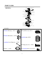
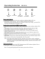
COOKER HOOD INSTRUCTION MANUAL Warning………………………………………………. Parts Name…………………………………………… NAME PAGE Model:RH-9021A Installation……………………………………………. Products and accessory …..………1 Installation Instruction………………………………. Caution………………………………………………... Dimensions………………………...2 Operation Instruction………………………………… Instruction…………………….…...3 Maintenance & Cleaning…………………………….. Caution…………………………….4 Trouble Shooting……………………………………… Operating Instruction……….…...5 Warranty & Wiring Diagram………………………. Maintenance & Cleaning…........6 Trouble Shooting…………………7 Wiring Diagram………………..…8 Specification………………………9 PART NAME Capacitor RH-9021A Control Board Electric Box Cover Electric Box Power cable Fan Blade (Right) Tube top cover Fan Blade (Left) Motor Ventilator Body Ventilator seal Oil Plate Main Tube Unit Glass Body Oil Cup LED Light Switch cover Body Press Button Control Panel Mesh Filter Switch Base Accessories Aluminium Tube (up) (1 PCS) Aluminium Tube (down) Charcoal Filter Assy (1 PCS) (1 PCS) Aluminium pipe (1 PCS) Aluminium Cover Fixing Assy (1 PCS) For Fixing Assy screw Connector (1 PCS) (2 PCS) For Aluminium Tube screw (3 PCS) 1 Dimensions MODEL A RH-9021A B 153(6") 510 300 mm min 460 max 900 mm (*Excluding with height of main unit) C mm 298 60mm 896 mm mm 510 2 C 210mm 896mm 510mm 896 Hook Location A 210 B Installation 1. Main Set Installation: The minimum distance between the cooker and the appliance is 75-90CM, and drill holes on the wall. Screw the main set by using screw nut together. Adjust the main set till horizontal line. min 75-90CM 650mm Keep it horizontal (level) 保持水平 2. Aluminium Tube Installation: Aluminium Tube Set Installation Diagram Install aluminium tube bracket according to the kitchen cabinet design. Find the suitable location and install it on the wall.(fig 1) mm 298 F ig.1 300 mm Aluminium tube install(1) Adjust alum inium tube height according to the kitchen cabinet design.Insert the alumin ium tube into the indentation.(fig 2 ) Fig. 2 Aluminiu m tube install(2) Screw the upper aluminium tube and the bracket(fig 3) 60mm 896 mm mm 510 Fig. 3 3 min 460 max 900 mm (*Excluding with height of main unit) Alumin ium tube bracket install Caution Surrounding Environment: The cooker hood should install near outdoor window. Let the exhaust air from the tube blow out easily thru the window. Alternatively, make a hole on the wall, and let the exhaust air from the aluminium tube blow out. Do not squash the aluminium tube into the hole. However, do not select a place, where has too many windows. That is because excess ventilation might affect the result of the (fig1) cooker hood.(fig1) Warning: Unplug the power socket before uninstall. 1. Please keep a minimum 75 –90 cm distance between cooker hood and cooker. Different types of cooker might require a bigger space.(fig2) min 75-90cm 650mm (fig2) 2. Do not flame under the cooker hood. (fig3) (fig3) 3. Adjust the aluminium tube to make sure all the exhaust air has blown out successful. 4. There shall be adequate ventilation of the room when the cooker hood is used at the same time as appliances burning gas or other fuels. 5. Accessible parts may become hot when used with cooking appliances. 6. The air must not be discharged into a flue that is used for exhausting fumes from appliances burning gas or other fuels. 7. The screw must tighten up after fixing the cooker hood. 4 Operating Instruction Light Control Button Turbo Button RH-9021A Middle Speed Control Button Low Speed Control Button Power. Control Button Power control button 1. Push this button to turn on the power and power indicator light will be on . 2. Push again to turn off power、power indicator light and all functions. Note:If power has been turned on over 9 minutes without any setting , system will be shut down automatically for energy-saving. Speed setting control button &Delay timer setting 1. Push turbo button to start extremely turbo ventilation and turbo indicator light will be on. * Push again will turn to extremely turbo delay function and turbo indicator light will be blink, system will shut down automatically after 3 minutes. 2. Push middle speed button to turn on middle speed ventilation and middle speed indicator light will be on . * Push again will turn to low speed delay function, low speed indicator light will be blink and shut down automatically after 90 seconds. 3. Push low speed button to turn on low speed ventilation and low speed indicator light will be on. * Push again will turn to low speed delay function and low speed indicator light will be blink, system will shut down automatically after 90 seconds. Note: Push turbo button during the delay function will set back to turbo ventilation; push middle speed button during the delay function will set back to middle speed ventilation; push low speed button during the delay function will set back to low speed ventilation. Light control button 1. Push this button to turn on the LED illumination and LED indicator light will be on. 2. Push again to turn off the LED illumination. Note : If only push Light/Speed/Turbo button, power also will be on. 5 Maintenance & Cleaning…. 1. There is a fire risk if cleaning is not carried out in accordance with the instructions. 2. Be careful of the flame when cooking alcoholic food. It might cause to burn the cooker hood. 3. Make sure the ventilation is good when using glass hob and cooker hood together. 4. Wipe the cooker hood with a soft damp cloth. 5. Do not spray water directly on the cooker hood to avoid electric shock or damage to it. 6. Use mild detergent to clean the impeller. Pull out the oil cup, and wash it. 7. Always wash or change the filter, and clean up the cooker hood regularly. 8. Minimum clean up the cooker hood once a week. 9. Kindly follow this cleaning instruction to avoid dangerous. 10. If the supply cord is damaged, it must be replaced by the manufacturer, its service agent or similarly qualified persons in order to avoid a hazard. 11. While having grease to filter, please pull down and wash. 6 Trouble Shooting 1. Motor Malfunction: Check the electrical wiring. Check the power plug, On / Off switch, or fuse. Check the impeller. If can move by hand when power is on, means the condenser capacitor needed to be changed. When turn on the motor, it stops immediately, or only 1 motor works, means you need to change a new motor. 2. Main Set Shaking: Check on the welding spots for losing points. Have the motor and impeller screwed properly. Has the impeller deformed? 3. Weak Suction: Far distance between cooker hood and glass hob? Check if aluminum pipe is too long or curve. Change to 7-inch diameter if necessary. Check if there is excess ventilation. Check the aluminum pipe, make sure exhaust air and flame blow out smoothly. Window should be closed while operating cooker hood. 4. Oil Plate Broke: Please get the original parts from any authorize dealers. 5. Oil Cup Broke: Please get the original parts from any authorize dealers. 6. Light Failure: Check if wiring is ok. Remove the light lampshade, and change a new LED light. 7. While filter have damaging, please pull down and change the new filter. 7 Wiring Diagram RH-9021A BLACK MOTOR BLACK ( BROWN) FUSE POWER WHITE ELECTRIC BOARD WHITE GRAY BLACK BLUE WHITE LAMP CONDENSER YELLOW Control Board LAMP 8 YELLOW WHITE ( BLUE) GRAY BLACK BLUE BROWN WHITE Specification MODEL RH-9021A DATA MATERIAL SIZE OUTLET DIA FAN SIZE MOTOR, S INSULATION VOLTTAGE/FREQUENCY AMP LIGHT SPEED MOTOR SPEED CONSUMPTION POWER AIR FLOW MAX C.O.O SUS430+Glass W896xD510xH520~960mm (*Height: From button of main unit) 153mm 14CMx2 1 E 240V/50Hz 1.5A 2W Ⅰ Ⅱ 1200rpm 180W 600m³/hr 1800rpm 220W 900m³/hr TAIWAN 9 Ⅲ 2400rpm 270W 1200m³/hr