1
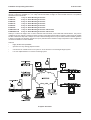
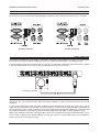
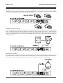
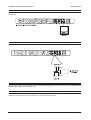
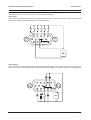
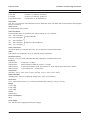
IP Series Codec Installation Instructions Please read this manual before installing your equipment IP Series Codec Installation and Operating Instructions IMPORTANT The first few pages of these instructions contain important information on safety and product conformity. Please read, and ensure that you understand this information before continuing. TO PREVENT FIRE OR SHOCK HAZARD, DO NOT EXPOSE THIS APPLIANCE TO RAIN OR MOISTURE Page 2 Installation and Operating Instructions IP Series Codec CONTENTS Product Safety ............................................................................................................................................................................................ 4 Electromagnetic Compatibility (EMC) ...................................................................................................................................................... 4 EU Conformance Statement ...................................................................................................................................................................... 4 Regulatory Notices ..................................................................................................................................................................................... 4 Unpacking ..................................................................................................................................................................................................... 4 Overview ....................................................................................................................................................................................................... 5 IP-CODEC General Layout .......................................................................................................................................................................... 6 Front Panel Indicators .................................................................................................................................................................................. 6 Connectors Overview ................................................................................................................................................................................... 7 Power Connections ...................................................................................................................................................................................... 7 19 Rack Mounting ....................................................................................................................................................................................... 7 Camera Connections (Encoder Only) .......................................................................................................................................................... 8 Video Output Connections (Decoder Only) .................................................................................................................................................. 9 Audio Connections (Encoder and Decoder) ................................................................................................................................................ 9 Setting the IP Address .................................................................................................................................................................................. 9 MAC Address ................................................................................................................................................................................................ 9 Serial Port Connections .............................................................................................................................................................................. 10 Configuration Switches ............................................................................................................................................................................... 11 Video Mode Switches ................................................................................................................................................................................. 11 Serial Data Connector Pin-out Diagram ..................................................................................................................................................... 12 Alarm I/O Connector Pin-out Diagram ....................................................................................................................................................... 13 Specifications .............................................................................................................................................................................................. 14 Page 3 IP Series Codec Installation and Operating Instructions PRODUCT SAFETY Please follow these instructions as you install your IP Series Codec and retain them for its lifetime. If you encounter any problems contact your agent. Installation is only to be carried out by competent, qualified and experienced personnel. Wire in accordance with the National Wiring regulations applicable to the country of installation. Failure to do so can result in death or injury by electric shock. A means of disconnecting the equipment from the mains supply must be provided as part of the installation and must be situated close by. BEFORE UNDERTAKING ANY INSTALLATION OR MAINTENANCE, THE MAINS SUPPLY MUST BE DISCONNECTED. Each internal printed circuit board carries a replaceable fuse. For continued protection against the risk of fire, replace with a fuse of the same type - 1.5 A (T) 125V. The equipment supplied with this manual is designed for use in a general purpose CCTV installation and has no other function. Do not exceed the voltage and temperature limits given in the specifications. Only use your IP Series Codec in a clean, dry, dust-free environment unless a suitable protective housing is provided. Electrical Safety British Standard BSEN60950:2000 Safety of information technology equipment, including electrical business equipment. ELECTROMAGNETIC COMPATIBILITY (EMC) Radio Frequency Emmissions Federal Communications Commission Code of federal regulations part 15. British Standard BSEN55022:1998 Limits and methods of measurement of radio disturbance characteristics of information technology equipment. This is a Class A product. In a domestic environment this product may cause radio interference in which case the user may be required to take adequate measures. Immunity British Standard BSEN50130-4 Alarm Systems Part 4 Electromagnetic compatibility Product family standard: Immunity requirements for components of fire, intruder and social alarm systems. MANUFACTURERS DECLARATION OF CONFORMANCE A Declaration of Conformity in accordance with the above EU standards has been made and is on file at Baxall Limited, Stockport SK6 2SU, England. The manufacturer declares that the product supplied with this document is compliant with the provisions of the EMC Directive 89/336 and associated amendments, and the Low Voltage Directive LVD 73/23 EEC. UNPACKING Keep your packaging for use if the product is to be stored for an extended period or needs to be returned for any reason. The packaging should contain: IP Series Codec Mains cable 19 rack mounting brackets and screws These Instructions Check the product code on the serial number label. If you have an incorrect item or it is damaged then inform the suppliers and carriers immediately. If this is the case then do not attempt to use the equipment. Page 4 Installation and Operating Instructions IP Series Codec OVERVIEW Baxall Destiny IP Series Codecs comprise a single hardware unit that may be configured to function as an encoder or as a decoder. Codecs are available in 1, 2 or 4-way units housed within a single 19 rack-mounted enclosure. The products described in this manual are: IP-ENC1-R 1-way 19 Rack Mounting IP Encoder IP-ENC2-R 2-way 19 Rack Mounting IP Encoder IP-ENC4-R 4-way 19 Rack Mounting IP Encoder IP-DEC1-R 1-way 19 Rack Mounting IP Decoder IP-DEC2-R 2-way 19 Rack Mounting IP Decoder IP-DEC4-R 4-way 19 Rack Mounting IP Decoder IP-ENC1DEC1-R 1-way 19 Rack Mounting IP Encoder and Decoder IP-ENC2DEC2-R 2-way 19 Rack Mounting IP Encoder and Decoder Destiny IP Codecs can support PAL or NTSC multicast video and audio, control data and external alarms. They can be configured over the network to function as either encoders or decoders and are able to transmit a video stream at variable bit rates of between 8 Kbps and 1.5 Mbps. The codecs data channel(s)can be set up for RS232, RS422 or RS485 operation to allow for integration of third party pan-tilt-zoom (PTZ) units and dome cameras. Image compression is pre-configured to use either the MJPEG or H261 standard. Features: Highly flexible and expandable. Operates over any existing physical network. Can function as a stand-alone CCTV system or as an extension to an existing analogue system. Low-cost implementation of a remote monitoring system. IP System Schematic Page 5 IP Series Codec Installation and Operating Instructions IP-CODEC GENERAL LAYOUT Single-way IP CODEC Front and Rear Panels (IP-ENC1-R and IP-DEC1-R) Two-way IP CODEC Front and Rear Panels (IP-ENC2-R, IP-DEC2-R and IP-ENC1DEC1-R) Four-way IP CODEC Front and Rear Panels (IP-ENC4-R, IP-DEC4-R and IP-ENC2DEC2-R) Note: On combined Encoder/Decoder units, the decoder modules are always on the right hand side of the unit when viewed from the front. Powering-up the unit will allow this to be determined by observing the state of the ENC/DEC led. EN C /D AU EC D IO SE R IA SE L I R N IA L O N U TS T C /P VI AL D ST AT PO W E AC R TI VE FRONT PANEL INDICATORS NETWORK Each channel of the IP-Codec has a common set of led indicators whose function is described below. POWER This led indicates that power is supplied to the unit. ACTIVE This led flashes to indicate that the unit is functioning correctly ENC/DEC This led indicates the functional mode of the IP-Codec. If the led is off, the unit is in the DECODER mode. If the led is ON, the unit is in the ENCODER mode. AUDIO This led indicates that audio streaming is taking place from, or to the unit. SERIAL IN This led indicates that serial data streaming to the unit is taking place. SERIAL OUT This led indicates that serial data streaming from the unit is taking place. NTSC/PAL This led indicates the video mode of the unit. If the led is OFF, the unit is in NTSC video mode. If the led is ON, the unit is in PAL video mode. If the led flashes, this indicates video-loss or no video to the unit. VID STAT This led indicates the video streaming status of the unit. If the led is off, there is no video input to the device. If the led is on, video streaming is taking place. Page 6 Installation and Operating Instructions IP Series Codec CONNECTORS OVERVIEW Each channel of the IP-Codec has a common set of input and output connectors whose function is described below. Note that certain connectors are used differently depending on whether the unit is functioning as an Encoder or a Decoder. Encoder Connectors Decoder Connectors POWER CONNECTIONS The encoder is powered from an AC supply of 120-240VAC at 50-60Hz via the supplied IEC connector. The stripped and tinned end of the connector must be fitted with a 3 pole (Live, Neutral and Earth) Class 1 grounding-type plug. The power supply cord should be routed so that it is not likely to be walked on or pinched by items placed upon or against it. Pay particular attention to the cord at the plug, and the point where it exits from the unit. 120-240 VAC, 50-60Hz 19 RACK MOUNTING Brackets and screws are supplied to enable the IP Codec to be rack mounted. They must be fitted prior to installation of the unit into the rack. If the unit has had the rubber feet fitted for desktop use, these are best removed for ease of rack installation. It is also recommended that a cable outlet plate or blanking plate be fitted between each pair of IP Codec units. This will assist with cable management and maintain good airflow between IP Codecs thus providing adequate heat dissipation. Where large numbers of IP Codecs are fitted into an enclosure (particularly along with other equipment), it is important that an overall heat calculation is performed to ensure that all the equipment is kept within its rated temperature range. Mains power distribution and system earthing should be carried out in accordance with national standards (BS7671 in the UK). Note that if miniature circuit breakers (MCBs) are used, they must be of a type suitably rated to accommodate the switch-on surge current of the power supply. Page 7 IP Series Codec Installation and Operating Instructions CAMERA CONNECTIONS (ENCODER ONLY) Analogue Camera Connection Analogue cameras are connected to an IP Codec that is configured to function as an Encoder. Up to four analogue cameras can be connected to each channel of an IP Codec as shown below. Note that only one camera can be viewed at any one time i.e. the unit does not provide multiplexing functionality. Pan/Tilt/Zoom Camera Connection A camera equipped with a pan/tilt/zoom head may be connected to the IP Codec (configured as an Encoder) as shown below. The video output from the camera is always connected to the number one video input (VID IN 1). Telemetry signals for the PTZ head are passed by an IP Receiver via the 9 way Data input/output connector on the rear of the encoder. A single PTZ camera/receiver may be connected to each channel of an IP Codec. The remaining video inputs can be used for other video sources. Dome Camera Connection Dome cameras are connected to an IP Codec configured to function as an Encoder as shown below. The video output from the camera is always connected to the number one video input (VID IN 1). Refer to the dome cameras instructions for the control data connection details. A single dome camera may be connected to each channel of an IP Codec. Page 8 Installation and Operating Instructions IP Series Codec VIDEO OUTPUT CONNECTIONS (DECODER ONLY) A system monitor is connected to the VID I/O BNC connecter of an IP Codec that is configured to function as a Decoder as shown below. AUDIO CONNECTIONS (ENCODER AND DECODER) Audio Line in and Line out signals are available on each channel of an IP Codec via a stereo 3.5mm jack socket. SETTING THE IP ADDRESS The user may configure the IP address, sub-net mask and default gateway. This is achieved by use of the Properties and Network options within the administrator tool. MAC ADDRESS The MAC address is normally transparent to the user and is pre-programmed at the factory. The programmed address is indicated on a label located on the underside of the unit towards the rear panel. Page 9 IP Series Codec Installation and Operating Instructions SERIAL PORT CONNECTIONS Destiny IP Codec units can be connected via an RS232, RS422 or RS485 network. The illustrations below show the different connection details for each of these protocols. The DIP switches shown set the biasing/termination for each type of network. Note that depending on whether the IP Codec is at the beginning or end of the network, or whether it is located somewhere between the beginning and end points of the network, the biasing/termination settings will be different. RS232 Network Connection RS485 (2-wire) Network Connection and Biasing/Termination Details Note that the switch settings for all END units are the same, and for all MID units. Page 10 Installation and Operating Instructions IP Series Codec SERIAL PORT CONNECTIONS RS422 (4-wire) Network Connection and Biasing/Termination Details Note that the switch settings for all END units are the same, and for all MID units. CONFIGURATION SWITCHES Each channel of the IP Codec contains two rows of eight DIP switches. The basic function of the dip switches is described below. Video Mode Switches This switch allows you to select the video standard (PAL or NTSC) of the connected video source or monitor. The factory default setting is for PAL. Config Switches These switches are used in conjunction with the configuration software and allow you to select whether the IP Codec functions as an Encoder or as a Decoder. The switches route the video signals to the VID4 BNC connector allowing a common connector to be used as either an input or an output. Note, however, that the correct software must be installed and the switches set correctly for each unit to operate. Page 11 IP Series Codec Installation and Operating Instructions CONFIGURATION SWITCHES Video Termination Switches These switches allow you to individually select whether each video source is terminated or not. The termination impedance is 75W. The default setting for a device configured as an Encoder is for each video source to be terminated. Note, where the Codec is configured as a Decoder, these switches should always be set to OFF (i.e. not terminated). SERIAL DATA CONNECTOR PIN-OUT DIAGRAM 1 2 3 4 5 SERIAL PIN RS232 RS422 RS485 2 Rx Rx- Rx- 3 Tx Tx- Tx- 5 Ground - - 7 RTS Tx+ Tx+ 8 CTS Rx+ Rx+ 6 7 8 9 Serial Connector Pin-out Details Note: For RS485 connections, the installer must link pin 2 to pin 3, and pin 7 to pin 8 on the back of the connector itself. Pins 1, 4, 6 and 9 are not connected. Page 12 Installation and Operating Instructions IP Series Codec ALARM I/O CONNECTOR PIN-OUT DIAGRAM Connections for the alarm inputs and outputs for each channel are provided by a 15-way D-type connector. The input pinouts and output pin-outs for the connector are shown separately for clarity. Alarm Inputs Alarm inputs are via internal opto-isolators. The example below is shown connected to volt-free contacts and an external isolated power supply. Note that pins 8 and 15 are internally linked. Alarm Outputs Alarm outputs are via internal open collector transistor rated at 24V, 250mA. The example below shows connections to lamps, an LED and a relay all powered via an external isolated power supply. Note that pins 8 and 15 are internally linked. Page 13 IP Series Codec Installation and Operating Instructions SPECIFICATIONS Part Number IP Encoder: IP-ENC1-R; IP-ENC2-R; IP-ENC4-R IP Decoder: IP-DEC1-R; IP-DEC2-R; IP-DEC4-R IP Encoder/Decoder IP-ENC1DEC1-R; IP-ENC2DEC2-R Description One, two or four channel video transmitter/receiver with duplex audio, full duplex data communications and integrated Ethernet connection. Video Format Pre-programmed H.261; MJPEG. Video Resolutions Interchangeable choice of resolutions from 704 x 576 pixels to 176 x 144 pixels. 4CIF: 704 x 576 pixels VGA: 640 x 480 pixels CIF: 352 x 288 pixels SIF: 352 x 240 pixels Supports MJPEG Supports H.261 and MJPEG QCIF: 176 x 144 pixels Video performance Up to 25/30 fps at CIF resolution with H.261; up to 15 fps at CIF resolution with MJPEG Audio Bi-directional. Pre-configured to G711 (or optionally G728) compression Network Protocols Internet IP, TCP, UDP, ICMP, ARP and IGMP with configuration via administrations tools Interfaces LAN data rate: 8 Kbps up to 1.5 Mbps Data Interface: RS232, RS422 or RS485 at 120 bps - 11.5 Kbps Alarm Interface: 6 inputs and 6 outputs. Inputs opto-isolated, TTL level; Outputs open collector 24V, 250mA Audio interface: Line-in and line-out, 1 V peak-peak. Temperature Operating: -10OC to +50OC (14OF to 122OF); Storage: -10OC to +70OC (14OF to 158OF) Relative humidity Operating: 20% - 80% non-condensing; Storage: 20% - 90% non-condensing Dimensions 1U 19 metal unit that houses 1, 2 or 4 video encoder/decoders. 482.6 (L) x 44 (H) x 138 (W) Weight 1-way: 2.2kg 2-way: 2.4kg 4-way: 2.8kg Colour Graphite grey Power consumption 50 W Power supply 120 - 240 VAC (auto-ranging) 50/60Hz (auto-ranging) Page 14 Installation and Operating Instructions IP Series Codec Page 15 Baxall Limited, Stockport, England. Visit our Web site: http://www.baxall.com Baxall Limited reserve the right to make changes to the product and specification of the product without prior notice to the customer. HB-IP-CODEC-2 Issue 2 10/01