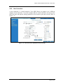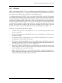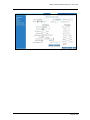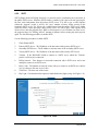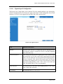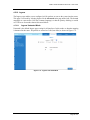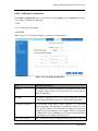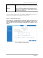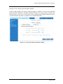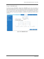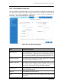
1
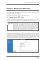
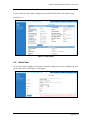
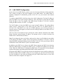
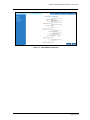
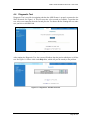
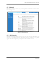
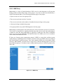
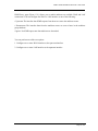
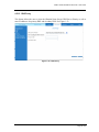
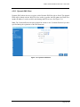
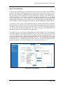
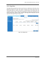
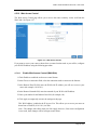
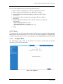
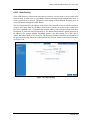
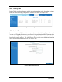
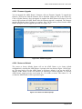
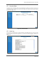
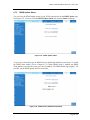
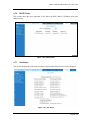
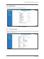
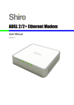
ADSL2+ Ethernet USB Combo Router - User Guide
Page 1 of 67
ADSL2+ Ethernet USB Combo Router - User Guide
Table of Contents
Preliminary Pages
Page
Table of Contents............................................................................................................. 2
List of Illustrations .......................................................................................................... 5
Chapter 1 - About this Manual ...................................................................................... 9
1.1
Introduction .................................................................................. 9
1.2
Scope and Purpose ........................................................................ 9
1.3
Targeted Audience ........................................................................ 9
1.4
Manual Organization..................................................................... 9
Chapter 2 – ADSL Ethernet Router Description......................................................... 10
2.1
ADSL Router Overview.............................................................. 10
Chapter 3 - Your Gateway At A Glance ...................................................................... 11
3.1
Ports and Buttons ........................................................................ 11
3.2
ADSL Router Overview.............................................................. 12
3.2.1
Front Indicators........................................................................... 12
3.2.2
Back Panel .................................................................................. 13
Chapter 4 - Setting Up the ADSL Router .................................................................... 14
4.1
Logging into your ADSL Router ................................................. 14
4.2
Quick Start.................................................................................. 15
4.3
LAN / DHCP Configuration........................................................ 16
4.4
Diagnostic Test ........................................................................... 18
4.4.1
Ping Test..................................................................................... 19
4.4.2
Modem Test................................................................................ 19
4.5
Advanced.................................................................................... 20
4.5.1
WAN Connection........................................................................ 20
4.5.2
New Connection ......................................................................... 21
4.5.3
ADSL Modulation ...................................................................... 22
4.5.4
Connection Scan ......................................................................... 23
4.5.5
Quickstart ................................................................................... 24
4.5.6
LAN Configuration ..................................................................... 26
4.5.7
LAN Clients................................................................................ 27
4.5.8
Application (UPnP)..................................................................... 28
4.5.9
SNTP .......................................................................................... 29
4.5.10
IGMP Proxy................................................................................ 30
Page 2 of 67
ADSL2+ Ethernet USB Combo Router - User Guide
4.5.11
TR-068 WAN Access ................................................................. 32
4.5.12
DNS Proxy.................................................................................. 33
4.5.13
Dynamic DNS Client .................................................................. 34
4.5.14
Port Forwarding .......................................................................... 35
4.5.15
Bridge Filters .............................................................................. 36
4.5.16
Web Access Control.................................................................... 37
4.5.16.1 Enable Web Access Control (WAN-Side)................... 37
4.5.17
QoS............................................................................................. 39
4.5.18
Egress ......................................................................................... 40
4.5.18.1 No Egress Mode ......................................................... 40
4.5.18.2 Egress Layer 2 Configuration ..................................... 41
4.5.18.3 Egress Layer 3 Configuration ..................................... 42
4.5.19
Ingress ........................................................................................ 43
4.5.19.1 Ingress Untrusted Mode.............................................. 43
4.5.19.2 Ingress Layer 2 Configuration..................................... 44
4.5.19.3 Ingress Layer 3 Configuration..................................... 46
4.5.19.4 Ingress Static Configuration........................................ 48
4.5.20
QoS Shaper Configuration .......................................................... 49
4.5.21
Policy Routing Configuration...................................................... 53
4.5.22
Static Routing ............................................................................. 56
4.5.23
Routing Table ............................................................................. 57
4.5.24
System Password ........................................................................ 57
4.5.25
Firmware Upgrade ...................................................................... 58
4.5.26
Restore to Default ....................................................................... 58
4.6
Security....................................................................................... 59
4.6.1
IP Filters ..................................................................................... 59
4.6.2
LAN Isolation ............................................................................. 60
4.7
Status .......................................................................................... 61
4.7.1
Connection Status ....................................................................... 62
4.7.2
System Log ................................................................................. 62
4.7.3
Remote Log Settings ................................................................... 63
4.7.4
Network Statistics ....................................................................... 63
4.7.5
DDNS Update Status................................................................... 64
4.7.6
DHCP Clients ............................................................................. 65
4.7.7
QoS Status .................................................................................. 65
4.7.8
Modem Status ............................................................................. 66
Page 3 of 67
ADSL2+ Ethernet USB Combo Router - User Guide
4.7.9
Product Information .................................................................... 66
4.8
Help ............................................................................................ 67
Page 4 of 67
ADSL2+ Ethernet USB Combo Router - User Guide
List of Illustrations
Figure
Page
Figure 1-1 : ADSL Router Configuration Diagram .......................................................... 10
Figure 1-2 : Front Panel Indicators (For Ethernet USB Combo Router) ........................... 12
Figure 1-3 : Back Panel Indicators (For Ethernet USB Combo Router)............................ 13
Figure 1-4 : Quick Start ................................................................................................... 14
Figure 1-5 : Basic Home.................................................................................................. 15
Figure 1-6 : Quick Start Page........................................................................................... 15
Figure 1-7 : LAN / DHCP Configuration ......................................................................... 17
Figure 1-8 : Diagnostics Test Screen................................................................................ 18
Figure 1-9 : Diagnostics Test Result Screen..................................................................... 18
Figure 1-10 : Ping Test Screen......................................................................................... 19
Figure 1-11 : Modem Test ............................................................................................... 19
Figure 1-12 : Advanced Screen........................................................................................ 20
Figure 1-13 : New Connection (PPPoE Connection Setup) .............................................. 21
Figure 1-14 : ADSL Modulation (Modem Setup)............................................................. 22
Figure 1-15 : Connection Scan......................................................................................... 23
Figure 1-16 : Quickstart (PPPoE Connection Setup) ........................................................ 25
Figure 1-17 : LAN Configuration .................................................................................... 26
Figure 1-18 : LAN Clients ............................................................................................... 27
Figure 1-19 : UPnP.......................................................................................................... 28
Figure 1-20 : SNTP ......................................................................................................... 29
Figure 1-21 : IGMP Proxy ............................................................................................... 30
Figure 1-22 : TR-068 WAN Access................................................................................. 32
Figure 1-23 : DNS Proxy................................................................................................. 33
Figure 1-24 : Dynamic DNS Client.................................................................................. 34
Page 5 of 67
ADSL2+ Ethernet USB Combo Router - User Guide
Figure 1-25 : Port Forwarding ......................................................................................... 35
Figure 1-26 : Bridge Filters ............................................................................................. 36
Figure 1-27 : Web Access Control................................................................................... 37
Figure 1-28 : No Egress................................................................................................... 40
Figure 1-29 : Egress Layer 2............................................................................................ 41
Figure 1-30 : Egress Layer 3............................................................................................ 42
Figure 1-31 : Ingress Untrusted Mode.............................................................................. 43
Figure 1-32 : Ingress Layer 2 Configuration .................................................................... 44
Figure 1-33 : Ingress Layer 3 Configuration .................................................................... 46
Figure 1-34 : Ingress Static Configuration ....................................................................... 48
Figure 1-35 : QoS Shaper Configuration.......................................................................... 49
Figure 1-36 : HTB Queue Discipline enabled .................................................................. 50
Figure 1-37 : Low Latency Queue Discipline enabled...................................................... 51
Figure 1-38 : PRIOWRR enabled .................................................................................... 52
Figure 1-39 : Policy Routing Configuration ..................................................................... 53
Figure 1-40 : Static Routing............................................................................................. 56
Figure 1-41 : Routing Table............................................................................................. 57
Figure 1-42 : System Password........................................................................................ 57
Figure 1-43 : Firmware Upgrade...................................................................................... 58
Figure 1-44 : Restore to Default prompt .......................................................................... 58
Figure 1-45 : Security...................................................................................................... 59
Figure 1-46 : IP Filters..................................................................................................... 59
Figure 1-47 : LAN Isolation ............................................................................................ 60
Figure 1-48 : Status ......................................................................................................... 61
Figure 1-49 : Connection Status....................................................................................... 62
Figure 1-50 : System Log ................................................................................................ 62
Figure 1-51 : Remote Log Settings .................................................................................. 63
Figure 1-52 : Network Statistics ...................................................................................... 63
Page 6 of 67
ADSL2+ Ethernet USB Combo Router - User Guide
Figure 1-53 : DDNS Update Status.................................................................................. 64
Figure 1-54 : DDNS Status (DDNS Client Enabled) ........................................................ 64
Figure 1-55 : DHCP Clients............................................................................................. 65
Figure 1-56 : QoS Status.................................................................................................. 65
Figure 1-57 : Modem Status ............................................................................................ 66
Figure 1-58 : Product Information ................................................................................... 66
Figure 1-59 : Help Screen................................................................................................ 67
Page 7 of 67
ADSL2+ Ethernet USB Combo Router - User Guide
Safety Summary Messages
WARNING
HIGH VOLTAGE
is used in the equipment. Make sure equipment is properly grounded
BEFORE opening. Failure to observe safety precautions may result in electric
shock to user.
CAUTION
Check voltages before connecting equipment to power supplies. Wrong
voltages applied may result in damage to equipment.
Page 8 of 67
ADSL2+ Ethernet USB Combo Router - User Guide
Chapter 1 - About this Manual
1.1
Introduction
This manual provides a general product overview and description of its subsystems and
components and basic operation and preventive maintenance instructions of the ADSL2+
Ethernet & USB Combo Router.
1.2
Scope and Purpose
This manual provides the following:
•
An overview of the ADSL2+ Ethernet & USB Combo Router system configuration and
connectivity;
•
General description and specifications of the ADSL2+ Ethernet & USB Combo Router
system components;
•
Operating instructions of the system and equipment;
1.3
Targeted Audience
This manual is designed and developed for the operators and users who are required to operate
and perform first-level maintenance of the ADSL2+ Ethernet & USB Combo Router. It assumes
the user of this manual has basic knowledge and experience in operating similar modem
configuration and computer systems equipment.
1.4
Manual Organization
The manual is divided into the following chapters:
1.
Chapter 1 – About this Manual; this chapter provides an introduction to the manual’s
scope and purpose, targeted audience and contents organisation.
2.
Chapter 2 – ADSL Ethernet Router Description; this chapter provides the system
description and system configuration diagram of ADSL Router connection.
3.
Chapter 3 – Your Gateway At A Glance; this chapter provides an overview of ports and
LEDs, Front and Back indicators of the ADSL Router.
4.
Chapter 4 – Setting Up the ADSL Router; this chapter provides description of all function
within the Web User Interface.
Page 9 of 67
ADSL2+ Ethernet USB Combo Router - User Guide
Chapter 2 – ADSL Ethernet Router Description
The ADSL2+ Ethernet & USB Combo Router is the perfect high-speed WAN bridge/router.
This full-featured product is specifically designed to connect to the Internet and directly connect
to your local area network via high speed 10/100 Mbps Ethernet. The ADSL Router has also full
NAT firewall and DMZ services to block unwanted users from accessing your network.
For game users, the ADSL Router had already pre configured for several low latency game ports.
Just click on the game you are playing on line and the rest is done for you.
The ADSL Router is fully compatible with all PCs; as long as the PC supports an Ethernet
interface and is running a TCP/IP protocol stack, your PC can have high-speed WAN access.
So, plug in the ADSL Router (refer to easy start guide), configure it (per your ISP’s
requirements) and enjoy the fast Internet access like never before.
2.1
ADSL Router Overview
Figure 1-1 shows the system configuration diagram of a typical ADSL Router connection.
Computer/Notebook with
USB Port
USB
Ethernet Switch/Hub
Ethernet
Computer/Notebook with
Ethernet Network Card
Figure 1-1 : ADSL Router Configuration Diagram
Page 10 of 67
ADSL2+ Ethernet USB Combo Router - User Guide
Chapter 3 - Your Gateway At A Glance
The ADSL2+ Ethernet & USB Combo may have different ports and LEDs. Let’s take a look at
the different options. Depending on your model, it may have some or all of the features listed
below.
3.1
Ports and Buttons
Reset and Restore to Factory Defaults: The restore to factory defaults feature will set the
ADSL Router to its factory default configuration by resetting the ADSL Router. You may need
to place the ADSL Router into its factory defaults if the configuration is changed; you lose the
ability to interface to the ADSL Router via the web interface, or following a software upgrade.
To reset the ADSL Router, simply press the reset button for about ~ 10 seconds. The ADSL
Router will be reset to its factory defaults and after about 30 ~ 40 seconds the ADSL Router will
become operational again.
LAN (local area network) ETHERNET port: connects to Ethernet network devices, such as a
PC, hub, switch, or routers. Some ADSL Router came with a single LAN connection and some
come with four LAN connections. Depending on the connection, you may need a cross over
cable or a straight through cable.
Power is where you connect the power. Make sure to observe the proper power requirements.
The required power is 9 volts.
USB (universal serial port): connects to a PC’s USB port. The ADSL Router only supports
Window’s based PCs via an RNDIS driver (included in the software). For model with USB port
ONLY.
DSL port: This is the WAN interface that connects directly to your phone line.
Page 11 of 67
ADSL2+ Ethernet USB Combo Router - User Guide
3.2
ADSL Router Overview
3.2.1
Front Indicators
Figure 1-2 shows the front indicators of the ADSL Router.
2
1
3
4
5
Figure 1-2 : Front Panel Indicators (For Ethernet USB Combo Router)
LED Name
Status & Meaning
1 PPP
Lights up when the PPP connection is established.
2 PWR
Lights up when power is supplied to the Router.
3 DSL
Lights up when the ADSL connection is established.
Flickers when the ADSL Router is trying to establish a connection with
the ADSL Service Provider.
4 ETH/ACT
Lights up when the Ethernet cable is properly connected from your
ADSL Router to the Ethernet Card.
Flickers when the ADSL is transmitting / receiving data.
5 USB
Lights up when the USB device driver is successfully installed in your
Computer/ Notebook.
Page 12 of 67
ADSL2+ Ethernet USB Combo Router - User Guide
3.2.2
Back Panel
Figure 1-3 shows the back panel indicators of the ADSL Router.
2
1
4
3
5
Figure 1-3 : Back Panel Indicators (For Ethernet USB Combo Router)
Label
Description
1 DSL
Telephone jack (RJ-11) to connect to your Telephone Wall Socket
(ADSL line).
2 USB
USB Port to connect to the USB port on your Computer/Notebook.
3 ETHERNET
10/100 Base-T Auto-MDI/MDIX (allows either cross or straight
cable) Ethernet jack (RJ-45) to connect to your Ethernet Network
card or Ethernet Hub/Switch.
4 RESET
To reset the ADSL Router, simply press the reset button for about
10 seconds (all customised settings that you have saved will be
lost!).
5 DC 9V
To connect to the Power Adapter that comes with your package.
Page 13 of 67
ADSL2+ Ethernet USB Combo Router - User Guide
Chapter 4 - Setting Up the ADSL Router
This section will guide you through your ADSL Router’s configuration. The ADSL Router is
shipped with a standard PPP configuration.
The basic tabs consist of features which are catered for basic users.
4.1
Logging into your ADSL Router
To configure your ADSL Router, open your web browser. You may get an error message at this
point; this is normal. Type the default IP address (10.0.0.138) on the web address bar.
NOTE: Before setting up your ADSL Router, make sure you have followed the
easy start guide. You should have your computers configured for DHCP
mode and have proxies disabled on your browser. Upon accessing the
ADSL Router, if the browser still displays a login redirection screen, you
should check your browser's setting and ensure that the JavaScript support
is enabled. If the screen shown in Figure 1-4 is not attainable, you must
delete your temporary Internet files to clear the web cache.
Upon entering the default IP address or the short-cut name (login.router), if the user is logging
for the first time, the user will be brought to the “Quick Start” page. See Figure 1-4. The Quick
Start page is meant for basic users whom only require easy connectivity to the Internet without
worrying about any other advance configuration setting. If you are in doubt for what content to
enter for the Protocol, VPI and VCI, please contact your Service Provider for assistance.
Figure 1-4 : Quick Start
Page 14 of 67
ADSL2+ Ethernet USB Combo Router - User Guide
For those who have their routers configured, you will be directed to the “Basic Home” page.
See Figure 1-5.
Figure 1-5 : Basic Home
4.2
Quick Start
If you have already configured your router and wish to change your current configuration, click
on the ‘Quick Start’ link. Figure 1-6 will appear.
Figure 1-6 : Quick Start Page
Page 15 of 67
ADSL2+ Ethernet USB Combo Router - User Guide
4.3
LAN / DHCP Configuration
On one side of your ADSL Router, you have your own Local Area Network (LAN) connections.
This is where you plug in your local computers to the ADSL Router. The ADSL Router is
normally configured to automatically provide all the PC's on your network with Internet
addresses.
To enable or disable DHCP, click Basic, then select LAN Configuration. The Start IP Address is
where the DHCP server starts issuing IP addresses. This value must be greater than the ADSL
Router IP address value. For example if the ADSL Router IP address is 192.168.1.1 than the
starting IP address must be 192.168.1. 2 (or higher).
The End IP Address is where the DHCP server stops issuing IP addresses. The ending address
cannot exceed a subnet limit of 254. Hence the max value for our default gateway is
192.168.1.254. If the DHCP server runs out of DHCP addresses, users will not get access to
network resources. If this happens you can increase the Ending IP address (to the limit of 255) or
reduce the lease time.
The Lease Time is the amount of time a network user will be allowed connection to the ADSL
Router with their current dynamic IP address. The amount of time is in units of minutes; the
default value is 3600 minutes (60 hours).
Note: If you change the start or end values, make sure the values are still within the same subnet
as the gateways IP address. In other words, if the gateways IP address is 192.168.1.1 and you
change the DHCP start/end IP addresses to be 192.128.1.2/192.128.1.100, you will not be able to
communicate to the ADSL Router if your PC has DHCP enabled.
In addition to the DHCP server feature, the ADSL Router supports the DHCP relay function.
When the ADSL Router is configured as DHCP server, it assigns the IP addresses to the LAN
clients. When the ADSL Router is configured as DHCP relay, it is responsible for forwarding the
requests and responses negotiating between the DHCP clients and the server.
By turning off the DHCP server and relay the network administrator must carefully configure the
IP address, Subnet Mask and DNS settings of every computer on your network. Do not assign
the same IP address to more than one computer and your ADSL Router must be on the same
subnet as all the other computers. See Figure 1-7.
Page 16 of 67
ADSL2+ Ethernet USB Combo Router - User Guide
Figure 1-7 : LAN / DHCP Configuration
Page 17 of 67
ADSL2+ Ethernet USB Combo Router - User Guide
4.4
Diagnostic Test
Diagnostic Test is used for investigating whether the ADSL Router is properly connected to the
WAN Network. See Figure 1-8. This test may take a few seconds to complete. To perform the
test, select your connection from the list and press the Test button. Before running this test, make
sure you have a valid DSL link.
Figure 1-8 : Diagnostics Test Screen
After running the Diagnostic Test, the screen will indicate that the portion which pass or fail the
test. See Figure 1-9. Please click on the Help links, which will provide remedy to the problem.
Figure 1-9 : Diagnostics Test Result Screen
Page 18 of 67
ADSL2+ Ethernet USB Combo Router - User Guide
4.4.1
Ping Test
Once you have your ADSL Router configured, ensure you can ping the network. Type the target
address that you want to ping. If your PC is connected to the ADSL Router via the default DHCP
configuration, you should be able to ping the network address 192.168.1.1. See Figure 1-10. If
your ISP has provided their server address, try to ping the address. If the pings for both the WAN
and the LAN sides are complete and you have the proper protocols configured, you should be
able to surf the Internet. By default when you select ping test, the ADSL Router will ping itself 3
times. The ADSL Router passed the Ping test; this basically means that the TCP/IP protocol is up
and running. If the first Ping test does not pass, the TCP/IP protocol is not loaded for some
reason; you should restart the ADSL Router.
Figure 1-10 : Ping Test Screen
4.4.2
Modem Test
This test can be used to check whether your Modem is properly connected to the Network. Select
your connection from the list and press the ‘Test’ button. See Figure 1-11.
Figure 1-11 : Modem Test
Page 19 of 67
ADSL2+ Ethernet USB Combo Router - User Guide
4.5
Advanced
This mode is catered for advance users, a brief explanation of the links are listed as shown
below. See Figure 1-12.
Figure 1-12 : Advanced Screen
4.5.1
WAN Connection
The Wide Area Network (WAN) connection exists on the other side of the ADSL Router, also
referred to as a broadband connection. This WAN connection is different for every WAN
supplier. Most of the configuration you will perform will be for WAN connection.
Page 20 of 67
ADSL2+ Ethernet USB Combo Router - User Guide
4.5.2
New Connection
A new connection is a virtual connection. Your ADSL Router can support up to 8 different
(unique) virtual connections. If you have multiple different virtual connections, you may need to
utilize the static and dynamic routing capabilities of the modem to pass data correctly. Refer to
Figure 1-13.
Figure 1-13 : New Connection (PPPoE Connection Setup)
Page 21 of 67
ADSL2+ Ethernet USB Combo Router - User Guide
4.5.3
ADSL Modulation
To configure the DSL modulation type, click WAN, ADSL Modulation. This will bring up the
modem setup screen. Leave the default value if you are unsure or the DSL/ISP did not provide
this information. In most cases, this screen should not be modified. See Figure 1-14.
Figure 1-14 : ADSL Modulation (Modem Setup)
Page 22 of 67
ADSL2+ Ethernet USB Combo Router - User Guide
4.5.4
Connection Scan
This feature helps users to detect the PVC settings provided by the ISP. Before the router can
begin scanning the connection, the telephone line has to be plugged into the router. Click on
Scan to begin. See Figure 1-15.
Figure 1-15 : Connection Scan
Page 23 of 67
ADSL2+ Ethernet USB Combo Router - User Guide
4.5.5
Quickstart
PPPoE is also known as RFC 2516. It is a method of encapsulating PPP packets over Ethernet.
PPP or Point-to-Point protocol is a method of establishing a network connection/session between
network hosts. It usually provides a mechanism of authenticating users.
To configure the gateway for PPPoE, click on Advanced. Under WAN, select New Connection.
The default PPPoE connection setup is displayed. At the Type field select PPPoE and the PPPoE
connection setup page is displayed. Give your PPPoE connection a unique name; the name must
not have spaces and cannot begin with numbers. In this case the unique name is called quickstart.
Select the encapsulation type (LLC or VC); if you are not sure just use the default mode. Select
the VPI and VCI settings; your DSL service provider or your ISP will supply these. In this case
the DSL service provider is using 0, 100. Also select the quality of service (QoS); leave the
default value if you are unsure or the ISP did not provide this information. See Figure 1-16.
Following is a description of the different options:
1.
Username: The username for the PPPoE access; this is provided by your DSL service
provider or your ISP.
2.
Password: The password for the PPPoE access; this is provided by your DSL service
provider or your ISP.
3.
On-Demand: Enables on-demand mode. The connection will disconnect if no activity is
detected after the specified idle timeout value.
4.
Idle Timeout: Specifies that PPPoE connection should disconnect if the link has no activity
detected for n seconds. This field is used in conjunction with the On-Demand feature. To
ensure that the link is always active, enter a 0 in this field.
5.
Keep Alive: When on-demand option is not enable, this value specifies the time to wait
without being connected to your provider before terminating the connection. To ensure that
the link is always active, enter a 0 in this field.
6.
Enforce MTU: Check this box if you experience problems accessing the Internet over a
PPPoE connection. This feature will force all TCP traffic to conform with PPP MTU by
changing TCP Maximum Segment Size to PPP MTU.
Page 24 of 67
ADSL2+ Ethernet USB Combo Router - User Guide
Figure 1-16 : Quickstart (PPPoE Connection Setup)
Page 25 of 67
ADSL2+ Ethernet USB Combo Router - User Guide
4.5.6
LAN Configuration
You can change the ADSL Router’s IP address by, clicking LAN, and then LAN Configuration.
Select the options from LAN group 1 and click Configure.
Your ADSL Router’s default IP address and subnet mask are 192.168.1.1/255.255.255.0; this
subnet mask will allow the ADSL Router to support 254 users. If you want to support a larger
number of users you can change the subnet mask; but remember that the DHCP server is
defaulted to only give out 255 IP addresses. Further remember that if you change your gateways’
IP address and you have DHCP enabled, the DHCP configuration must reside within the same
subnet. The default gateway is the routing device used to forward all traffic that is not addressed
to a station within the local subnet. Your ISP will provide you with the default gateway address.
The hostname can be any alphanumeric word that does not contain spaces. The domain name is
used to in conjunction with the host name to uniquely identify the gateway. To access the ADSL
Router’s web pages, the user can type 192.168.1.1 (the default IP address) or type login.router.
The apply button will temporarily save this connection. To make the change permanent you need
to click on Save Settings (at the side of the page). See Figure 1-17.
Figure 1-17 : LAN Configuration
Page 26 of 67
ADSL2+ Ethernet USB Combo Router - User Guide
4.5.7
LAN Clients
To add a LAN client, select LAN clients option under LAN. If DHCP was enabled in the
configuration, all DHCP clients are automatically assigned with IP address. If a fixed IP address
server is on the LAN and you want this server to be visible via the WAN, you must add its IP
address. Once the IP address has been added, you can apply Port Forwarding and Access Control
rules to this IP address. See Figure 1-18.
Figure 1-18 : LAN Clients
Page 27 of 67
ADSL2+ Ethernet USB Combo Router - User Guide
4.5.8
Application (UPnP)
UPnP, NAT and Firewall Traversal allow traffic to pass-thru the ADSL Router for applications
using the UPnP protocol. This feature requires one active DSL connection. In presence of
multiple DSL connections, select the one over, which the incoming traffic will be present, for
example the default Internet connection.
To enable UPnP, you must first have a WAN connection configured. Once a WAN connection is
configured, click Advanced and under Application, select UPnP. You must enable UPnP and
then select which connection will utilize UPnP. See Figure 1-19.
Figure 1-19 : UPnP
Page 28 of 67
ADSL2+ Ethernet USB Combo Router - User Guide
4.5.9
SNTP
SNTP (Simple Network Timing Protocol) is a protocol used to synchronize the system time to
the public SNTP servers. When the SNTP feature is enabled, your router will start querying for
the time clock information from the primary SNTP server. If it fails to get a valid response
within the “timeout” period, it will try for “retry” number of times, before moving to the
Secondary SNTP server. If it fails to get a valid response from Secondary STNP server within
valid retry times, it starts querying Tertiary SNTP server. If it fails to get a valid response from
all the servers, then the program stops. When a valid response is received from one of the server,
the program sleeps for “Polling_interval” amount of minutes, before starting the whole process
again. Use the following procedures to enable SNTP.
Use the following procedures to enable SNTP.
1.
Check Enable SNTP.
2.
Primary SNTP Server - The IP address or the host name of the primary SNTP server.
3.
Secondary SNTP Server - The IP address or the host name of the secondary SNTP server.
4.
Tertiary SNTP Server - The IP address or the host name of the tertiary SNTP server.
5.
Timeout - If the DSL600EU failed to connect to a SNTP server within the ‘Timeout’
period, it will retry the connection.
6.
Polling Interval - Time between a successful connection with a SNTP server and a new
attempt to connect to an SNTP server.
7.
Retry Count - The number of times the router will try to connect to an SNTP server before
it try to connect to the next server in line.
8.
Time Zone - The time zone of the router.
9.
Day Light - Check/uncheck this option to enable/disable day light saving. See Figure 1-20.
Figure 1-20 : SNTP
Page 29 of 67
ADSL2+ Ethernet USB Combo Router - User Guide
4.5.10 IGMP Proxy
Multicasting is a form of limited broadcast. UDP is used to send datagrams to all hosts that
belong to what is called a Host Group. A host group is a set of one or more hosts identified by a
single IP destination address. The following statements apply to host groups:
• Anyone can join or leave a host group at will.
• There are no restrictions on a host’s location.
• There are no restrictions on the number of members that may belong to a host group.
• A host may belong to multiple host groups.
• Non-group members may send UDP datagrams to the host group.
Multicasting is useful when the same data needs to be sent to more than one device. For instance,
if one device is responsible for acquiring data that many other devices need, then multicasting is
a natural fit. Note that using multicasting as opposed to sending the same data to individual
devices uses less network bandwidth. The multicast feature also enables you to receive multicast
video streams from multicast servers.
IP hosts use Internet group management protocol (IGMP) to report their multicast group
memberships to neighboring routers. Similarly, multicast routers use IGMP to discover which of
their hosts belong to multicast groups. Your router supports IGMP proxy that handles IGMP
messages. When enabled, your router acts as a proxy for a LAN host making requests to join and
leave multicast groups, or a multicast router sending multicast packets to multicast groups on the
WAN side.
Figure 1-21 : IGMP Proxy
Page 30 of 67
ADSL2+ Ethernet USB Combo Router - User Guide
IGMP Proxy page (Figure 1-21) allows you to enable multicast on available WAN and LAN
connections. You can configure the WAN or LAN interface as one of the following:
• Upstream: The interface that IGMP requests from hosts are sent to the multicast router.
• Downstream: The interface data from the multicast router are sent to hosts in the multicast
group database.
• Ignore: No IGMP request nor data multicast are forwarded.
You can perform one of the two options:
1. Configure one or more WAN interface as the upstream interface.
2. Configure one or more LAN interface as the upstream interface.
Page 31 of 67
ADSL2+ Ethernet USB Combo Router - User Guide
4.5.11 TR-068 WAN Access
The TR-068 WAN Access page (Figure 1-22) enables you to give temporary permission to
someone (such as technical support staff) to be able to access your router from the WAN side.
From the moment the account is enabled, the user is expected to log in within 20 active minutes,
otherwise the account expires. Once the user has logged in, if the session remains inactive for
more than 20 minutes, the user will be logged out and the account expires.
Figure 1-22 : TR-068 WAN Access
To create a temporary user account for a remote access to your router, follow the procedure
below.
1.
Check WAN Update to enable write privilege of the router.
2.
Check WAN Access to enable read privilege of the router.
3.
Enter a user name and password in the User Name and Password fields.
4.
Enter a port number In the Port field (for example, 51003).
5.
Click Apply to temporarily activate the settings on the page.
Note—The changes take effect when you click Apply; however, if the router configuration is not
saved, these changes will be lost upon reboot.
6.
To make the change permanent, click Save Settings.
7.
To access your router remotely, enter the following in the URL:
http(s)://WAN IP of router:Port Number
Page 32 of 67
ADSL2+ Ethernet USB Combo Router - User Guide
4.5.12 DNS Proxy
This feature allows the user to select the (Domain Name Server) DNS Server Priority as well as
enter IP addresses for primary DNS and secondary DNS. See Figure 1-23.
Figure 1-23 : DNS Proxy
Page 33 of 67
ADSL2+ Ethernet USB Combo Router - User Guide
4.5.13 Dynamic DNS Client
Dynamic DNS allows the user to register with a Dynamic DNS Provider as listed. The dynamic
DNS will be linked with the WAN IP of the router even after the ISP update the WAN IP to
another IP address. It can be useful in web hosting and FTP services. See Figure 1-24.
Note: The Username/Password entered should be similar to the Username/Password you have
specified during the registration of the DNS hostname.
Figure 1-24 : Dynamic DNS Client
Page 34 of 67
ADSL2+ Ethernet USB Combo Router - User Guide
4.5.14 Port Forwarding
Using the Port Forwarding page, you can provide local services (for example web hosting) for
people on the Internet or play Internet games. When users send this type of request to your
network via the Internet, the ADSL Router will forward those requests to the appropriate PC.
Port forwarding can be used with DHCP assigned addresses but remember that a DHCP address
is dynamic (not static). For example, if you were configuring a Netmeeting server, you would
want to assign this server a static IP address so that the IP address is not reassigned. Also
remember that if an Internet user is trying to access an Internet application, they must use the
WAN IP address. The port forwarding will translate the WAN IP address into a LAN IP address.
To configure a service, game, or other application select the external connection (for example the
Internet connection), from the Home screen, click Advanced and under Application, select Port
Forwarding. Next select the computer hosting the service and add the corresponding firewall
rule. If you want to add a custom application, select the User category, click New and fill in the
Rule Name, Protocol and Port number for your application.
For example, if you want to host a Netmeeting session, from the Home screen, click Advanced
and under Application, select Port Forwarding. First select the IP address for your Netmeeting
server. Next select the Audio/Video category and add Netmeeting to the applied rules box. To
view the management rules, highlight Netmeeting and select view; this will display the pre
configured protocols and ports that Netmeeting will use. Now assuming that your WAN
connection is correct, you can run Netmeeting from your server and call users that are on the
Internet. If you know your WAN IP address, users can call you. See Figure 1-25.
Figure 1-25 : Port Forwarding
Page 35 of 67
ADSL2+ Ethernet USB Combo Router - User Guide
4.5.15 Bridge Filters
The bridge filtering mechanism provides a way for the users to define rules to allow/deny frames
through the bridge based on source MAC address, destination MAC address and/or frame type.
When bridge filtering is enabled, each frame is examined against each defined filter rules
sequentially. When a match is determined, the appropriate filtering action (determined by the
access type selected i.e. allow or deny) is performed. Please note that the bridge filter will only
examine frames from interfaces, which are part of the bridge itself. Twenty filter rules are
supported with bridge filtering. See Figure 1-26.
Figure 1-26 : Bridge Filters
Page 36 of 67
ADSL2+ Ethernet USB Combo Router - User Guide
4.5.16 Web Access Control
The Web Access Control page allows you to access the router remotely via the web from the
WAN side. See Figure 1-27.
Figure 1-27 : Web Access Control
If you want to access your router at home from a remote location such as your office, configure
your WAN IP address using the following procedure.
4.5.16.1
Enable Web Access Control (WAN-Side)
1. Check Enable to enable the web access control feature.
2. In the Choose a connection field, select the connection used to connect to the Internet.
3. In the Remote Host IP field, enter the WAN-side IP address you will use to access your
router (for example, 10.10.10.1).
4. In the Remote Netmask field, enter the netmask of your WAN-side IP address.
5. Enter a port number In the Redirect Port field (for example, 80).
6. Click Apply to temporarily activate the settings on the page.
This WAN address is added to the IP Access List. This allows you to access you router at
home from a WAN IP (10.10.10.1) via Web.
Note—The changes take effect when you click Apply; however, if the router configuration
is not saved, these changes will be lost upon router reboot.
Page 37 of 67
ADSL2+ Ethernet USB Combo Router - User Guide
7. To access your router from the remote IP (10.10.10.1), enter the following in the
URL: http(s)://WAN IP of router:Port Number
Page 38 of 67
ADSL2+ Ethernet USB Combo Router - User Guide
4.5.17 QoS
QoS stands for Quality of service. The QoS framework allows network administrators to
configure the routers to meet the real time requirements for voice and video.
Different QoS marking is used in different network:
• ToS network: ToS bits in the IP header
• VLAN network: priority bits in the VLAN header
• DSCP network: uses only 5 bits of the CoS
• WLAN: WLAN QoS header
The QoS framework is supported on all the above domains. How do you make them talk to each
other? How can you make sure the priority from one network is carried over to another network?
Class of service (CoS) is introduced as the common language for the QoS mappings. When QoS
is enabled, the router has full control over packets from the time they enter the router till they
leave the router. This is how it works: The domain mapping (ToS bits, priority bits, etc.) of a
packet needs to be translated to CoS when the packet enter the router, and vice versa, the CoS of
a packet needs to be translated back to the domain mapping when the packet leaves the router.
There are 6 types of CoS (in descending priority):
•
•
•
•
•
•
CoS1
CoS2
CoS3
CoS4
CoS5
CoS6
The rules are:
1. CoS1 has absolute priority and is used for expedited forwarding (EF) traffic. This is always
serviced till completion.
2. CoS2-CoS5 are used for assured forwarding (AF) classes. They are serviced in a strict round
robin manner using the following priority scheme:
CoS2 > CoS3 > CoS4 > CoS5
3. CoS6 is for best effort (BE) traffic. This is only serviced when there is no other class of
service. If QoS is not enabled on your router, all traffic will be treated as best effort.
Page 39 of 67
ADSL2+ Ethernet USB Combo Router - User Guide
There are some additional terms you should get familiarize with:
•
•
•
•
•
•
Ingress: Packets arriving into the router from a WAN/LAN interface.
Egress: Packets sent from the router to a WAN/LAN interface.
Trusted mode: Honors the domain mapping (ToS byte, WME, WLAN
user priority).
Untrusted mode: Does not honor domain mapping. This is the default
QoS setting.
Traffic Conditioning Agreement (TCA): The TCA needs to be defined for
each interface:
– Ingress mappings (Domain =>CoS)
– Egress Mappings (CoS => Domain)
– By default, all interfaces are in Untrusted mode.
Shaper
4.5.18 Egress
For packets going out of the router, the marking (CoS) need to be translated to the mappings
understood by the network domains. The reverse CoS and domain mapping is configured using
the Egress page. This page is access by selecting Egress on the Advanced main page under QoS.
4.5.18.1
No Egress Mode
The default Egress page setting for all interfaces is No Egress. In this mode, the domain
mappings of the packets are untouched.
Figure 1-28 : No Egress
Page 40 of 67
ADSL2+ Ethernet USB Combo Router - User Guide
4.5.18.2
Egress Layer 2 Configuration
The Egress Layer 2 page allows you to map the CoS of an outgoing packet to user priority bits,
which is honoured by the VLAN network. Again, this feature is only configurable on the WAN
interfaces as VLAN is only supported on the WAN side in the current release.
Figure 1-29 : Egress Layer 2
Field
Definition/ Description
Interface
Select the WAN interface to configure the QoS for outgoing packets,
LAN interface cannot be selected as VLAN is currently supported
on the WAN side only.
Unclassified Packet
Some locally generated packets might not have been classified and
thus do not have a CoS value, such as PPP control packet and ARP
packet. You can define the CoS for all unclassified outgoing packets
on layer 2 using this field, which will then pick up the user priority
bits based on the mapping rules you create. The selections are (in the
order of descending priority): CoS1, CoS2, CoS3, CoS4, CoS5, and
CoS6. The default value is CoS1 (recommended).
Class of Service
The selections are (in the order of descending priority): CoS1, CoS2,
CoS3, CoS4, CoS5, and CoS6.
User Priority
The selections are 0, 1, 2, 3, 4, 5, 6, 7.
Page 41 of 67
ADSL2+ Ethernet USB Combo Router - User Guide
4.5.18.3
Egress Layer 3 Configuration
The Egress Layer 3 page enables you to map CoS to ToS so that the priority marking of outgoing
packets can be carried over to the IP network.
Figure 1-30 : Egress Layer 3
Field
Definition/ Description
Interface
Select the WAN/LAN interface here to configure the QoS for
outgoing traffic to the IP network.
Default Non-IP
Locally generated packets (such as ARP packets) do not have a CoS
marking. You can define the CoS for all unclassified outgoing
packets on layer 3 using this field. The selections are in the order of
descending priority): CoS1, CoS2, CoS3, CoS4, CoS5, and CoS6.
The default value is CoS1 (recommended).
Class of Service
The selections are (in the order of descending priority): CoS1, CoS2,
CoS3, CoS4, CoS5, and CoS6.
Translated ToS
The Type of Service field takes values from 1 to 255. The selections
are 0, 1, 2, 3, 4, 5, 6, 7.
Page 42 of 67
ADSL2+ Ethernet USB Combo Router - User Guide
4.5.19 Ingress
The Ingress page enables you to configure QoS for packets as soon as they come into the router.
This page is accessed by selecting Ingress on the Advanced main page under QoS. The domain
mappings are converted to CoS (the common language) so that the priority marking is carried
over. There are four modes that are discussed below:
4.5.19.1
Ingress Untrusted Mode
Untrusted is the default Ingress page setting for all interfaces. In this mode, no domain mapping
is honoured in the router. All packets are treated as CoS6 (best effort) as shown in Figure 1-31.
Figure 1-31 : Ingress Untrusted Mode
Page 43 of 67
ADSL2+ Ethernet USB Combo Router - User Guide
4.5.19.2
Ingress Layer 2 Configuration
Layer 2 page allows you to map an incoming packet with VLAN priority to CoS. This feature is
only configurable on the WAN interfaces as VLAN is only supported on the WAN side in the
current software release.
Figure 1-32 : Ingress Layer 2 Configuration
Field
Definition/ Description
Interface
Select the WAN interface here to configure the CoS for incoming
traffic. Only WAN interface can be selected as VLAN is currently
supported only on the WAN side.
Class of Service
The selections are (in the order of descending priority): CoS1, CoS2,
CoS3, CoS4, CoS5, and CoS6.
User Priority
The selections are 0, 1, 2, 3, 4, 5, 6, 7.
Page 44 of 67
ADSL2+ Ethernet USB Combo Router - User Guide
Ingress Layer 2 Priority Bits to CoS Configuration
1.
From Interface drop-down box, select quickstart.
You are configuring QoS on this WAN interface.
2.
Select CoS1 in Class of Service and 5 in Priority Bits.
Any packets with priority marking 5 is mapped to CoS1, the highest priority that is
normally given to the voice packets.
3.
Click Apply to temporarily activate the settings.
4.
Select CoS2 in the Class of Service field and 1 in the Priority Bits field. Any packets that
have a priority bits of 1 is mapped to CoS2, which is the second highest priority. This is
given to the high priority packets such as video.
5.
Click Apply to temporarily activate the settings.
Note—The changes take effect when you click Apply; however, if the router configuration
is not saved, these changes will be lost upon reboot.
6.
Repeat step 2-5 to add more rules to quickstart.
Up to eight rules can be configured for each interface.
Note—Any priority bits that have not been mapped to a CoS default to CoS6, the lowest
priority.
7.
Repeat step 1-6 to create rules to another WAN interface.
Note—Any WAN interface that is not configured has the default Untrusted mode.
Page 45 of 67
ADSL2+ Ethernet USB Combo Router - User Guide
4.5.19.3
Ingress Layer 3 Configuration
The Layer 3 page allows you to map ToS bits of incoming packets from the IP network to CoS
for each WAN/LAN interface.
Figure 1-33 : Ingress Layer 3 Configuration
Field
Definition/ Description
Interface
For both WAN and LAN interfaces, you can configure QoS for layer
3 (IP) data traffic.
Class of Service
This CoS field allows you to map incoming layer 3 WAN/LAN
packets to one of the following CoS (in the order of descending
priority): CoS1, CoS2, CoS3, CoS4, CoS5, and CoS6.
ToS
The Type of Service field takes values from 0 to 255.
Default Non-IP
A static CoS can be assigned to all layer 3 incoming packets (per
interface) that do not have an IP header, such as PPP control packets
and ARP packets. The default is CoS1 (recommended).
Page 46 of 67
ADSL2+ Ethernet USB Combo Router - User Guide
Ingress Layer 3 ToS to CoS Configuration
1.
From Interface drop-down box, select LAN Group 1.
You are configuring QoS on this interface.
2.
Select CoS1 in Class of Service and enter 22 in Type of Service (ToS).
Any incoming packet from LAN Group 1 (layer 3) with a ToS of 22 is mapped to CoS1,
the highest priority, which is normally given to the voice packets.
3.
Leave the default value CoS1 in Default Non-IP.
Any incoming packet from LAN Group 1 without an IP is mapped to CoS1, the highest
priority.
4.
Click Apply to temporarily activate the settings.
Note—The changes take effect when you click Apply; however, if the router configuration
is not saved, these changes will be lost upon reboot.
5.
Repeat step 2-4 to add more rules to LAN Group 1.
Up to 255 rules can be configured for each interface.
Note—Any ToS that have not been mapped to a CoS is treated as CoS6, the lowest
priority.
6.
Repeat step 1-5 to create rules to another WAN/LAN interface.
Note—Any WAN/LAN interface that is not configured has the default Untrusted mode.
7.
To make the change permanent, click Save Settings.
Page 47 of 67
ADSL2+ Ethernet USB Combo Router - User Guide
4.5.19.4
Ingress Static Configuration
The Ingress - Static page enables you to configure a static CoS for all packets received on a
WAN or LAN interface.
Figure 1-34 : Ingress Static Configuration
To configure, follow the following procedure to configure Ingress static QoS settings.
Ingress Static Configuration
1.
At the Interface drop-down box, select USB.
You are configuring QoS on this interface only. Any WAN/LAN interface that isnot
configured has the default Untrusted mode.
2.
Select CoS1 in Class of Service.
All incoming traffic from the USB interface receives CoS1, the highest priority.
3.
Click Apply to temporarily activate the settings.
Note—The changes take effect when you click Apply; however, if the router configuration
is not saved, these changes will be lost upon reboot.
Page 48 of 67
ADSL2+ Ethernet USB Combo Router - User Guide
4.5.20 QoS Shaper Configuration
The Shaper Configuration page is accessed by selecting Shaper on the Advanced main page.
Three shaper algorithms are supported:
• HTB
• Low Latency Queue Discipline
• PRIOWRR
Note—Egress TCA is required if shaper is configured for that interface.
Figure 1-35 : QoS Shaper Configuration
Field
Definition/ Description
Interface
The selections are WAN/LAN interfaces except WLAN, which does
not support Shaper feature. This field needs to be selected before
shaper configuration.
Max Rate
This field is applicable for the HTB Queue Discipline and Low
Latency Queue Discipline, both are rate-based shaping algorithms.
HTB Queue Discipline
The hierachical token bucket queue discipline is a rate-based
shaping algorithm. This algorithm rate shapes the traffic of a class
over a specific interface. All CoSx traffic is assigned a specific rate
to which data will be shaped to. For example: If CoS1 is configured
to 100Kbps then even if 300Kbps of CoS1 data is being transmitted
to the interface only 100Kbps will be sent out.
Low Latency Queue
This is similar to the above algorithm except that CoS1 is not rate
Page 49 of 67
ADSL2+ Ethernet USB Combo Router - User Guide
Discipline
limited. So in the example above CoS1 data is not rate limited to
100Kbps but instead all 300Kbps is transmitted. The side effect is
that a misconfigured stream can potentially take all bandwidth.
PRIOWRR
This is a priority based weighted round robin algorithm operating on
CoS2-CoS6. CoS1 queues have the highest priority and are not
controlled by the WRR algorithm.
Of the three shaping algorithms available on the Shaper Configuration page, only one can be
enabled at a time. An example of each configuration is given as follows.
Example 1: HTB Queue Discipline Enabled
In the example below, HTB Queue Discipline is enabled. The PPPoE1 connection has a total of
300 kbits of bandwith, of which 100 kbits is given to CoS1 and another 100 kbits is given to
CoS2. When there is no CoS1 or CoS2 packets, CoS6 packets have the whole 300 kbits of
bandwith.
Figure 1-36 : HTB Queue Discipline enabled
Page 50 of 67
ADSL2+ Ethernet USB Combo Router - User Guide
Example 2: Low Latency Queue Discipline Enabled
In this second example, Low Latency Queue Discipline is enabled. CoS1 is not rate controlled
(hence the field is disabled). CoS2 takes 100 kbits when there is no CoS1 packets. CoS6 has 300
kbits when there is no CoS1 or CoS2 packets. This is similar to the HTB queue discipline as they
are both rate-based algorithm, except that CoS1 is handled differently.
Figure 1-37 : Low Latency Queue Discipline enabled
Page 51 of 67
ADSL2+ Ethernet USB Combo Router - User Guide
Example 3: PRIOWRR Enabled
In this third example, PRIOWRR is enabled. Since PRIOWRR operates only on the number of
packets being transmitted, the max rate field has been disabled. Only percentage can be assigned
to the CoS2 - CoS6. CoS1 is not rate controlled (hence the field is not displayed). When there is
no CoS1 packets, CoS2, CoS3, CoS4 each has 10 percent, and CoS6 has 70 percent. This is
similarly to the Low Latency Queue discipline, except that one is packet-based, and the other is
rate-based.
Figure 1-38 : PRIOWRR enabled
Page 52 of 67
ADSL2+ Ethernet USB Combo Router - User Guide
4.5.21 Policy Routing Configuration
The Policy Routing Configuration page is accessed by selecting Policy Routing Configuration on
the Advanced home page under QoS. This page enables you to configure policy routing and
QoS. The policy routing configuration is discussed as follows. The QoS configuration is
discussed in ‘‘Ingress Payload Database Configuration’’.
Figure 1-39 : Policy Routing Configuration
Field
Definition/ Description
Ingress Interface
The incoming traffic interface for a Policy Routing rule. Selections
include LAN interfaces, WAN interfaces, Locally generated (traffic),
and not applicable. Examples of Locally generated traffic are: voice
packets, packets generated by applications such as DNS, DHCP, etc.
Destination Interface
The outgoing traffic interfaces for a Policy Routing rule. Selections
include LAN Interfaces and WAN interfaces.
DiffServ Code Point
The diffServ code point (DSCP) field value ranges from 1 to 255.
This field cannot be configured alone, addtional fields like IP,
Source MAC, and/or Ingress Interface should be configured.
Class of Service
The selections are (in the order of priority): CoS1, CoS2, CoS3,
CoS4, CoS5, CoS6, and N/A.
Source IP
The IP address of the traffic source.
Mask
The source IP netmask. This field is required if the source IP has
been entered.
Page 53 of 67
ADSL2+ Ethernet USB Combo Router - User Guide
Destination IP
The IP address of the traffic destination.
Mask
The netmask of the destination. This field is required if the
destination IP has been entered.
Protocol
The selections are TCP, UDP, ICMP, Specify, and none. If you
choose Specify, you need to enter the protocol number in the box
next to the Protocol field.
This field cannot be configured alone, addtional fields like IP,
Source MAC, and/or Ingress Interface should be configured.
This field is also required if the source port or destination port has
been entered.
Source Port
The source protocol port. You cannot configure this field without
entering the protocol first.
Destination Port
The destination protocol port or port range. You cannot configure
this field without entering the protocol first.
Source MAC
The MAC address of the traffic source.
Local Routing MAC
This field is enabled only when Locally Generated is selected in the
Ingress Interface field. The mark for DNS traffic generated by
different applications are described below:
• Dynamic DNS: 0xE1
• Dynamic Proxy: 0xE2
• Web Server: 0xE3
• MSNTP: 0xE4
• DHCP Server: 0xE5
• IPtables Utility: 0xE6
• PPP Deamon: 0xE7
• IP Route: 0xE8
• ATM Library: 0xE9
• NET Tools: 0xEA
• RIP: 0xEB
• RIP v2: 0xEC
• UPNP: 0xEE
Page 54 of 67
ADSL2+ Ethernet USB Combo Router - User Guide
• Busybox Utility: 0xEF
• Configuration Manager: 0xF0
• DropBear Utility: 0xF1
• Voice: 0
Currently routing algorithms make decision based on destination address, i.e. only Destination IP
address and subnet mask is supported. The Policy Routing page enables you to route packets on
the basis of various fields in the packet. The following fields can be configured for Policy
Routing:
•
Destination IP address/mask
• Source IP address/mask
• Source MAC address
• Protocol (TCP, UDP, ICMP, etc)
• Source port
• Destination port
• Incoming interface
•
DSCP
Page 55 of 67
ADSL2+ Ethernet USB Combo Router - User Guide
4.5.22 Static Routing
If the ADSL Router is connected to more than one network, you may need to set up a static route
between them. A static route is a pre-defined pathway that network information must travel to
reach a specific host or network. You can use static routing to allow different IP domain users to
access the Internet through the ADSL Router.
The New Destination IP is the address of the remote LAN network or host to which you want to
assign a static route. Enter the IP address of the host for which you wish to create a static route
here. For a standard Class C IP domain, the network address is the first three fields of the New
Destination IP, while the last field should be 0. The Subnet Mask identifies which portion of an
IP address is the network portion, and which portion is the host portion. For a full Class C
Subnet, the Subnet Mask is 255.255.255.0. The Gateway IP address should be the IP address of
the gateway device that allows for contact between the Gateway and the remote network or host.
See Figure 1-40.
Figure 1-40 : Static Routing
Page 56 of 67
ADSL2+ Ethernet USB Combo Router - User Guide
4.5.23 Routing Table
Routing Table shows the information used by routers when making packet forwarding decisions.
Packets are routed according to the packet's destination IP address. See Figure 1-41.
Figure 1-41 : Routing Table
4.5.24 System Password
You can change your ADSL Router’s username and password by clicking on System Password.
You can also change the idle timeout; you will need to log back onto the ADSL Router once the
timeout expires. If you forget your password, you can press and hold the reset to factory defaults
button for 10 seconds (or more). The ADSL Router will reset to its factory default configuration
and all custom configurations will be lost. See Figure 1-42.
Figure 1-42 : System Password
Page 57 of 67
ADSL2+ Ethernet USB Combo Router - User Guide
4.5.25 Firmware Upgrade
You can upgrade the ADSL Router’s firmware; click on Firmware Upgrade. To upgrade the
firmware, click browse, find the firmware file to download. Make sure this is the correct file.
Click on Update Gateway. Once the upgrade is complete the ADSL Router will reboot. You will
need to log back onto the ADSL Router after the firmware upgrade is completed. The firmware
upgrade should take about 5 minutes to complete. Note: Do not remove power from the ADSL
Router during the firmware upgrade procedure. See Figure 1-43.
Figure 1-43 : Firmware Upgrade
4.5.26 Restore to Default
The restore to factory defaults feature will set the ADSL Router to its factory default
configuration by resetting the ADSL Router. A prompt as the one shown in Figure 1-44 will popup. You may need to reset the ADSL Router to its factory default if you lose the ability to
interface ADSL Router via the web interface (or following a software upgrade). To reset the
ADSL Router, simply press the reset button for ~10 seconds (or more). After about 30 ~ 40
seconds the ADSL Router will be operational again.
Figure 1-44 : Restore to Default prompt
Page 58 of 67
ADSL2+ Ethernet USB Combo Router - User Guide
4.6
Security
The security feature section allows users to configure the following: See Figure 1-45.
•
IP Filters
•
LAN Isolation
Figure 1-45 : Security
4.6.1
IP Filters
IP filter is identical to Port blocking in Access Control. The router will block workstations with
defined IP range and port range. See Figure 1-46.
Figure 1-46 : IP Filters
Page 59 of 67
ADSL2+ Ethernet USB Combo Router - User Guide
4.6.2
LAN Isolation
LAN isolation allows you to disable the flow of packets up to three user-defined LAN groups
(WLAN, USB, and Ethernet). This allows you to secure information in private portions of the
LAN from other publicly accessible LAN segments.
Figure 1-47 : LAN Isolation
Page 60 of 67
ADSL2+ Ethernet USB Combo Router - User Guide
4.7
Status
This status section allows users to view the following connections and interfaces:
•
Connection Status
•
System Log
•
Remote Log
•
Network Statistics
•
DDNS Update Status
•
DHCP Clients
•
QoS Status
•
Modem Status
•
Product Information
Figure 1-48 : Status
Page 61 of 67
ADSL2+ Ethernet USB Combo Router - User Guide
4.7.1
Connection Status
Connection Status will display all the relevant information regarding your Internet Connection. It
will display the type of protocol used, the WAN IP address, the connection state and the duration
connected. See Figure 1-49.
Figure 1-49 : Connection Status
4.7.2
System Log
You can view the ADSL Router’s logged information. Depending upon the severity level, this
logged information will generate log reports to a remote host (if remote logging is enabled). See
Figure 1-50.
Figure 1-50 : System Log
Page 62 of 67
ADSL2+ Ethernet USB Combo Router - User Guide
4.7.3
Remote Log Settings
This feature is for users to enable remote logging. Settings mentioned below are essential for this
feature to work:
•
Log Level
•
Adding / Deleting IP address
•
Logging destination
Figure 1-51 : Remote Log Settings
4.7.4
Network Statistics
Information regarding the Status and Statistics of your Ethernet, USB and DSL line will be
displayed. See Figure 1-52.
Figure 1-52 : Network Statistics
Page 63 of 67
ADSL2+ Ethernet USB Combo Router - User Guide
4.7.5
DDNS Update Status
You can view the DDNS update status of your WAN connection from the DDNS Status page.
See Figure 1-53. To access, click the DDNS Update Status link from the Status main page.
Figure 1-53 : DDNS Update Status
As you can see from this page, the DDNS client is disabled by default for your router. To enable
the DDNS client feature, refer to Chapter 4.5.13. When DDNS client is enabled, the DDNS
client updates every time the router gets a new IP address. The DDNS Status page (Figure 1-54)
provides you the DDNS update status of your router.
Figure 1-54 : DDNS Status (DDNS Client Enabled)
Page 64 of 67
ADSL2+ Ethernet USB Combo Router - User Guide
4.7.6
DHCP Clients
This section shows the users connected. It also shows the MAC address, IP address, host name
and lease time.
Figure 1-55 : DHCP Clients
4.7.7
QoS Status
This section displays the QoS status and shows which packets have been received or dropped.
Figure 1-56 : QoS Status
Page 65 of 67
ADSL2+ Ethernet USB Combo Router - User Guide
4.7.8
Modem Status
This section displays the Modem status and DSL statistics.
Figure 1-57 : Modem Status
4.7.9
Product Information
This screen will show a summary of all the product information and software version that comes
bundled with the ADSL Router.
Figure 1-58 : Product Information
Page 66 of 67
ADSL2+ Ethernet USB Combo Router - User Guide
4.8
Help
The Help screen takes you to the different Help Sections for Firewall, Bridge Filters, LAN
Clients, LAN Group Configurations, PPP Connection, UPnP, IP QoS and RIP Help.
Figure 1-59 : Help Screen
© Copyright May 2006. All Rights Reserved
Page 67 of 67