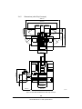
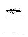
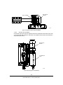
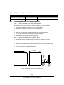
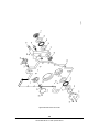
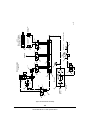
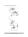
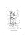
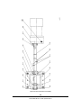
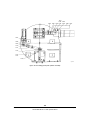
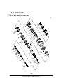
1
Copyright © 2008, XYZ Machine Tools, All rights are reserved. No part of this publication may be
reproduced, stored in a retrieval system, or transmitted, in any form or by any means, mechanical,
photocopying, recording or otherwise, without the prior written permission of XYZ Machine Tools.
While every effort has been made to include all the information required for the purposes of this guide,
XYZ Machine Tools, assumes no responsibility for inaccuracies or omission and accepts no liability for
damages resulting from the use of the information contained in this guide.
All brand names and products are trademarks or registered trademarks of their respective holders.
XYZ Machine Tools
Woodlands Business Park,
Burlescombe,
Nr Tiverton,
Devon, UK
EX16 7LL
UK and International Sales Enquiries
Tel: 01823 674 200
Fax: 01823 674 201
Overseas - All Enquiries
Tel: +44 (0)1823 674 200
Fax: +44 (0)1823 674 201
Spares Shop and Stores Department
Tel: +44 (0)1823 674 215
Fax: +44 (0)1823 672 919
Programming and Technical Support
Tel: +44 (0)1823 674 200
Fax: +44 (0)1823 674 201
Service Department
Tel: +44 (0)1823 674 214
Fax: +44 (0)1823 674 201
Used Machinery Department
Tel: +44 (0)1823 674 210
Fax: +44 (0)1823 674 201
Table of Contents
1.0
Introduction
1.1
2.0
Safety
2.1
3.0
May 08
Manual Organization ........................................................................................ 1
Safety Publications .......................................................................................... 3
2.2
Warnings, Cautions and Notes .......................................................................... 3
2.2.1
Warnings, Cautions and Notes Used in this Manual ............................................ 3
2.2.2
List of Warnings in this Manual ......................................................................... 3
2.3
Safety Precautions ..........................................................................................15
2.3.1
Operator Safety .............................................................................................15
2.3.2
Health and Safety at Work ..............................................................................15
2.3.3
Noise Level ....................................................................................................15
2.3.4
Operating Hazards .........................................................................................15
2.3.5
Operational Safety Precautions ........................................................................16
2.3.6
General Principles for Operator Safety when Operating the Machine ..................17
2.3.7
Safety Precautions for Operating the Centralized Lubrication System ..................19
Description
3.1
Vertical Machining Center Specifications ...........................................................22
3.1.1
Standard Equipment .......................................................................................22
3.1.2
Optional Equipment ........................................................................................23
3.1.3
Machine Specifications ....................................................................................23
3.1.4
Standard Dimensions ......................................................................................24
3.1.5
Dimensions (with Chip Conveyor) ....................................................................28
3.1.6
Head Assembly ..............................................................................................30
3.1.7
Feed Motion Transmission Mechanism .............................................................32
3.1.8
Automatic Tool Change (ATC) Mechanism (560 Mini Mill) ..................................36
3.1.9
Enclosure ......................................................................................................38
3.1.10
Dimensions of the Tool Holder ........................................................................39
3.2
Rotary Type Tool Changer Specifications ..........................................................40
3.3
Centralized Lubrication System Specifications ...................................................42
3.4
Control Specifications .....................................................................................44
3.4.1
System Configuration .....................................................................................44
3.4.2
Control Design ...............................................................................................44
3.4.3
Functionality ..................................................................................................44
3.4.4
Operating Modes ............................................................................................45
3.4.5
Contours and Compensations ..........................................................................45
3.4.6
Safety Functions ............................................................................................46
3.4.7
Programming .................................................................................................46
3.4.8
PLC ...............................................................................................................47
3.4.9
Operator Control Components .........................................................................47
3.4.10
Displays .........................................................................................................48
i
XYZ Machine Tools
KR-MF560 Operation Manual
Issue 01
4.0
5.0
Issue 01
3.4.11
Operation ......................................................................................................48
3.4.12
Communication ..............................................................................................48
3.4.13
Symbols and Abbreviations .............................................................................49
Shipping and Handling
4.1
Equipment .....................................................................................................51
4.2
Safety Precautions ..........................................................................................51
4.3
Machine weights and packing crate dimensions ................................................52
4.4
Lifting the Machine in it’s packing crate ............................................................52
4.4.1
Safety Precautions for Lifting the Machine ........................................................52
4.4.2
Lifting the Machine with a Forklift Truck ...........................................................52
4.4.3
Lifting the Machine with a Sling Crane or Other Lifting Equipment .....................53
4.5
Securing the Machine during transportation .....................................................53
4.5.1
Head .............................................................................................................53
4.5.2
Tool Magazine (560 Mini Mill Only) ..................................................................53
4.5.3
Operation Panel .............................................................................................54
4.5.4
Power Cabinet ...............................................................................................54
4.5.5
Miscellaneous .................................................................................................54
4.6
Remove transit fixtures from the Machine ........................................................54
4.7
Storage .........................................................................................................54
4.7.1
Storing the Machine with packaging .................................................................54
4.7.2
Storing the Machine without packaging ............................................................54
Installation
5.1
Preparation ....................................................................................................57
5.1.1
Space Requirements .......................................................................................57
5.2
Installation Location .......................................................................................59
5.2.1
Environmental Requirements ...........................................................................59
5.3
Foundation and Construction Plan ...................................................................59
5.3.1
Foundation Construction .................................................................................59
5.3.2
Foundation Construction Plan Two ...................................................................60
5.4
Levelling the Machine Vertical Machining Center ...............................................62
5.4.1
Adjusting the Machine ....................................................................................62
5.4.2
Adjusting the Square between the Spindle Centreline and the Working Table Surface
62
5.4.3
Adjust the Square Along the X, Y, Z Axis ..........................................................63
5.5
Electrical Requirement ....................................................................................64
5.5.1
Power Supply .................................................................................................64
5.5.2
Power Wiring .................................................................................................65
5.5.3
Grounding .....................................................................................................65
5.6
Installing the Lubrication System .....................................................................67
5.6.1
Installing the Lubricator ..................................................................................67
5.6.2
Filling the Centralized Lubrication System .........................................................68
5.6.3
Connecting the Oil Pipe ..................................................................................69
ii
XYZ Machine Tools
KR-MF560 Operation Manual
May 08
6.0
May 08
5.6.4
Installation of Power and Alarm to the Lubrication System ................................70
5.7
Inspection .....................................................................................................73
5.7.1
Before Power Start-up ....................................................................................73
5.7.2
After Power Start-up .......................................................................................73
Basic Operation
6.1
Machine Safety Equipment ..............................................................................75
6.2
Prior to Start Up .............................................................................................75
6.2.1
Pre-operation Inspection .................................................................................75
6.2.2
Safety Precautions ..........................................................................................75
6.2.3
Notices ..........................................................................................................75
6.3
Starting and Stopping the Machine ..................................................................76
6.3.1
Starting Procedure .........................................................................................76
6.3.2
Emergency Stop Procedure .............................................................................76
6.3.3
Normal Stop Procedure ...................................................................................76
6.4
Warm Up .......................................................................................................76
6.4.1
Notices ..........................................................................................................76
6.5
Preparation ....................................................................................................77
6.5.1
Safety Precautions ..........................................................................................77
6.5.2
Notices ..........................................................................................................77
6.5.3
Alarm messages .............................................................................................77
6.6
Operational Safety Precautions ........................................................................77
6.7
Referencing the Machine ................................................................................78
6.8
Manual Operation Procedure ...........................................................................78
6.8.1
Manual Operation Mode ..................................................................................78
6.8.2
Manual Feed Motion .......................................................................................78
6.8.3
Manual Rapid Traverse Feed ...........................................................................78
6.8.4
MPG Feed Motion ...........................................................................................78
6.9
Starting and Stopping the Spindle Rotation ......................................................79
6.10
Automatic Tool Change (ATC) Procedure .........................................................79
6.10.1
Tool Mounting ................................................................................................79
6.10.2
Manual Tool Change .......................................................................................79
6.10.3
Tool Change in MDI Mode ...............................................................................79
6.10.4
ATC Edged Tool Change .................................................................................84
6.11
Automatic Operation .......................................................................................86
6.11.1
Preparation ....................................................................................................86
6.11.2
Automatic Operation Procedure .......................................................................86
6.11.3
No Load Test Run Procedure ...........................................................................86
6.11.4
Automatic Cutting Operation ...........................................................................86
6.12
Switching Off Procedure .................................................................................87
6.13
Post-operation Maintenance ............................................................................87
6.13.1
Notices ..........................................................................................................87
iii
XYZ Machine Tools
KR-MF560 Operation Manual
Issue 01
7.0
8.0
Adjustment
7.1
Spindle Transmission Belt Tension ...................................................................89
7.2
Adjustment of Table Gib .................................................................................90
7.3
Adjustment of Saddle Gib ...............................................................................90
7.4
Adjustment of Headstock Gib ..........................................................................91
7.5
Adjustment of the Square Between the Spindle Centre Line and the Table Surface
92
7.6
Adjust the Square Along the X, Y and Z Axes ...................................................93
7.7
Adjustment of Cam and Bearings .....................................................................94
7.8
Adjustment of the Rotary Tool Changer Arm ....................................................96
Maintenance
8.1
9.0
10.0
Issue 01
Preparation Before Maintenance ......................................................................97
8.2
Centralized Lubrication System Maintenance ....................................................97
8.2.1
Warning System for the Centralized Lubrication System ....................................97
8.3
Lubrication ....................................................................................................97
8.3.1
Lubrication for the X, Y and Z Axis Bearings .....................................................97
8.3.2
Lubrication for the X, Y and Z Axis Ballscrews ...................................................98
8.3.3
Lubrication and Cooling of the Spindle System .................................................98
8.3.4
Oil Guide Table ..............................................................................................98
8.4
Machine Maintenance .....................................................................................98
8.4.1
Notices ..........................................................................................................98
8.4.2
Cleaning the Machine .....................................................................................98
8.5
Preventative Maintenance ...............................................................................99
8.5.1
Daily Maintenance ..........................................................................................99
8.5.2
Weekly Maintenance .......................................................................................99
8.5.3
Monthly Maintenance ......................................................................................99
8.5.4
Half Yearly Maintenance .................................................................................99
8.5.5
Yearly Maintenance ...................................................................................... 100
8.5.6
Three Yearly Maintenance ............................................................................. 100
8.6
Rotary Tool Changer Maintenance ................................................................. 100
8.6.1
To Remove a Tool from the Rotary Tool Changer ........................................... 100
8.6.2
Remove the Spline (Output) Shaft ................................................................. 103
Fault Finding
9.1
Fault Finding the BT40 Rotary Tool Changer .................................................. 107
9.2
Fault Finding the Centralised Lubrication System ............................................ 108
Parts List
10.1
XYZ Mini Mill 560 Parts List ........................................................................... 111
10.1.1
XYZ Mini Mill 560 Assembly ........................................................................... 112
10.1.2
Spindle Drive Assembly ................................................................................. 114
10.1.3
Head Assembly ............................................................................................ 117
10.1.4
Table Assembly ............................................................................................ 120
iv
XYZ Machine Tools
KR-MF560 Operation Manual
May 08
11.0
May 08
10.1.5
Saddle Assembly .......................................................................................... 123
10.1.6
Base Assembly ............................................................................................. 126
10.1.7
Column Assembly ......................................................................................... 128
10.1.8
Magazine Assembly ...................................................................................... 131
10.1.9
ATC Sensor Assembly ................................................................................... 134
10.1.10
ATC Cam Box Assembly ................................................................................ 140
10.1.11
Lubricator Assembly ..................................................................................... 144
10.1.12
Guard Assembly ........................................................................................... 147
10.1.13
Coolant Tank ............................................................................................... 149
10.1.14
Chip and Swarf Conveyors ............................................................................ 152
10.1.15
Pneumatic Assembly ..................................................................................... 154
10.2
Rotary Type Tool Changer Parts List .............................................................. 155
10.2.1
Tool Magazine Transmission .......................................................................... 156
10.2.2
Driving Sprocket Assembly ............................................................................ 158
10.2.3
Motor Transmission Assembly ....................................................................... 161
10.2.4
Tool Falling Cylinder Assembly ...................................................................... 163
10.2.5
Tool Falling Guide Plate Cylinder Assembly ..................................................... 165
10.2.6
Support Block Assembly ................................................................................ 167
10.2.7
ATC Adjusting Block Assembly ....................................................................... 169
10.2.8
ATC Protector Assembly ................................................................................ 171
10.2.9
ATC Sensor Assembly ................................................................................... 173
10.2.10
Tool Change Arm Assembly ........................................................................... 175
10.2.11
Input Shaft .................................................................................................. 177
10.2.12
Output Shaft ................................................................................................ 179
10.2.13
Idler Sprocket and Rocker ............................................................................. 181
10.2.14
Signal .......................................................................................................... 183
Parts List
11.1
XYZ VMC 710 Parts List ................................................................................. 185
11.1.1
Spindle Drive Assembly ................................................................................. 186
11.1.2
Head Assembly ............................................................................................ 189
11.1.3
Table Assembly ............................................................................................ 192
11.1.4
Saddle Assembly .......................................................................................... 195
11.1.5
Base Assembly ............................................................................................. 198
11.1.6
Column Assembly ......................................................................................... 200
11.1.7
Magazine Assembly ...................................................................................... 202
11.1.8
ATC Assembly .............................................................................................. 205
11.1.9
ATC Cam Box Assembly ................................................................................ 211
11.1.10
Lubricator Assembly ..................................................................................... 215
11.1.11
Guard Assembly ........................................................................................... 218
11.1.12
Coolant Tank ............................................................................................... 220
11.1.13
Chip Conveyor ............................................................................................. 222
11.1.14
Pneumatic Assembly ..................................................................................... 224
v
XYZ Machine Tools
KR-MF560 Operation Manual
Issue 01
12.0
13.0
11.2
Rotary Type Tool Changer Parts List .............................................................. 225
11.2.1
Tool Magazine Transmission .......................................................................... 226
11.2.2
Driving Sprocket Assembly ............................................................................ 228
11.2.3
Motor Transmission Assembly ....................................................................... 231
11.2.4
Tool Falling Cylinder Assembly ...................................................................... 233
11.2.5
Tool Falling Guide Plate Cylinder Assembly ..................................................... 235
11.2.6
Support Block Assembly ................................................................................ 237
11.2.7
ATC Adjusting Block Assembly ....................................................................... 239
11.2.8
ATC Protector Assembly ................................................................................ 241
11.2.9
ATC Sensor Assembly ................................................................................... 243
11.2.10
Tool Change Arm Assembly ........................................................................... 245
11.2.11
Input Shaft .................................................................................................. 247
11.2.12
Output Shaft ................................................................................................ 249
11.2.13
Idler Sprocket and Rocker ............................................................................. 251
11.2.14
Signal .......................................................................................................... 253
Machine Wiring
12.1
Machine Wiring ............................................................................................ 255
12.2
Rotary Tool Changer Wiring .......................................................................... 306
12.2.1
Electrical Action Sequence ............................................................................ 308
Warranty
13.1
Issue 01
Warranty for the Machine ............................................................................. 313
vi
XYZ Machine Tools
KR-MF560 Operation Manual
May 08
1.0 Introduction
The machine is one product of the Vertical Machining Center series which is supplied by XYZ
Machine Tools Ltd.
The machine consists of a bed base, headstock, main column, saddle, working table, operation
panel, hydraulics, lubrication system, chip conveyor, chip collecting equipment, safety guards
and CNC controllers, etc.
The machine is designed to machine workpieces that do not generate powder chips, corrosion
or flammable substances, such as magnesium alloy.
The machine has a centralized lubrication system which is designed to lubricate various
components such as ball bearings, flat bearings, flat slideways, circular slideways, linear
guides, cams, gears, chains, etc.
This manual gives details of how to install, operate, adjust and maintain the machine.
Please carefully read all of the manuals provided. Do not use the machine unless you
understand how to operate and stop the machine, and also understand all of the safety
matters. Please contact us with any queries you may have.
1.1
Manual Organization
Section 2 of this manual provides important safety information. All operators of this product
must review this safety information.
Section 3 describes the functions of the machine, rotary type tool changer and centralized
lubrication system, complete with a full technical specification.
Section 4 gives details on the shipping and handling of the machine.
Section 5 introduces the operator to the installation procedure.
Section 6 gives an overview of the operation modes available and general operational
procedures.
Section 7 gives details of adjustments which the operator may be required to make.
Section 8 gives details of the maintenance procedures to be done by the operator.
Section 9 lists the common faults for the rotary type tool changer and the centralized
lubrication system.
Section 10 gives details of the parts lists for the 560 Mini Mill, rotary tool changer and
centralized lubrication system.
Section 11 gives details of the parts lists for the 710 Vertical Maching Center, rotary tool
changer and centralized lubrication system.
Section 12 provides an overview of the wiring for the machine.
Section 13 contains the standard warranty for the machine.
July 08
1
XYZ Machine Tools
XYZ 560 Mini Mill and 710 VMC Operation Manual
Issue 01
Issue 01
2
XYZ Machine Tools
XYZ 560 Mini Mill and 710 VMC Operation Manual
July 08
2.0 Safety
The safe operation of the machine depends on its correct use and the precautions taken by the
operator.
2.1
•
Read and understand this manual. Make sure the operator understands the operation
and safety requirements of the machine before operating it.
•
Always wear the correct personal protective equipment.
•
Do not wear gloves, rings, watches, long sleeves, neckties, jewellery or any other loose
items when around or operating the machine.
•
Obey the necessary COSHH and risk assessments.
•
The machine is to be only used for the milling and drilling of cold metal within the stated
capacity of the machine and axes movement by manual use of handwheels, jogstick or
CNC control.
•
The machine must only be operated by trained and experienced operators.
•
The machine must be used in a standard workshop environment and is not suitable for
potentially explosive atmosphere.
•
Any other use of the machine must be subjected to a risk assessment by a responsible
person.
Safety Publications
The following publications must be obeyed to ensure the safe use of the machine.
EC Machinery Directive 2006/42/EC and Power Provision and Use of Work Equipment
Regulations.
2.2
Warnings, Cautions and Notes
2.2.1
Warnings, Cautions and Notes Used in this Manual
WARNING - Hazards or unsafe practices that may result in severe personal injury
or death. These are orange in colour.
Caution - Hazards or unsafe practices that could result in minor personal injury and/
or damage to the equipment. These are yellow in colour.
Note - Calls attention to specific issues regarding special attention or understanding.
2.2.2
List of Warnings in this Manual
WARNING - The machine is equipped with safety devices. Do not modify any safety
devices on this machine. If changes to these safety devices are made, XYZ Machine
Tools will not be responsible for any issues of product liability. Any changes will also
invalidate any remaining warranty entitlement.
July 08
3
XYZ Machine Tools
XYZ 560 Mini Mill and 710 VMC Operation Manual
Issue 01
WARNING - When the noise level is high in the working environment, wear earplugs
and appropriate personal protective equipment to prevent injury.
WARNING - Make sure the machine has fully stopped before opening the one-piece
door. If the door is opened during operation the machine stops to protect the
operator from debris, cutting coolant and moving parts. Make sure you close the onepiece front door before you start the machine.
WARNING - Do not lift the machine with lifting equipment that does not conform to
the load capacity. This can result in personal injury and damage to the machine and
equipment.
WARNING - Lethal Voltages. Use suitably qualified electricians to install and
maintain the machine electrical equipment. Failure to do so will result in a lethal
electric shock or serious injury.
WARNING - Danger of electrical shock. Do not turn on power before the protective
grounding has been correctly connected. Failure to do so will result in a lethal electric
shock or serious injury.
WARNING - Before operating the machine, make sure the wires and cables are
insulated correctly to prevent electric shock and serious injury.
WARNING - Risk of serious injury. Make sure the main power supply to the machine
is isolated and warning signs are displayed before inspecting the belt tension. Failure
to isolate the main power supply can result in serious injury.
Issue 01
4
XYZ Machine Tools
XYZ 560 Mini Mill and 710 VMC Operation Manual
July 08
xyz-173
Figure 1 Warning and danger signs on the machine
July 08
5
XYZ Machine Tools
XYZ 560 Mini Mill and 710 VMC Operation Manual
Issue 01
xyz-174
Figure 2 Warning and danger signs on the machine (continued)
Issue 01
6
XYZ Machine Tools
XYZ 560 Mini Mill and 710 VMC Operation Manual
July 08
xyz-175
Figure 3 Warning and danger signs on the machine (continued)
July 08
7
XYZ Machine Tools
XYZ 560 Mini Mill and 710 VMC Operation Manual
Issue 01
xyz-176
Figure 4 Warning and danger signs on the machine (continued)
Issue 01
8
XYZ Machine Tools
XYZ 560 Mini Mill and 710 VMC Operation Manual
July 08
CAUTION
To ensure the spindle continues to run smoothly and have a long life, please
run up the spindle as recommended below.
(1) Only run the spindle carrying a tool. Never run the spindle without tool.
Please note the dynamical balance requirements of tools for high speed.
(O)
(X)
(2) Procedure for warming up the spindle
Situation
Spindle Speed
Time
(Max Speed= 100%rpm)
(Minute)
Check Items
A
Daily Running
30%
15
1. Any noise
2. Any abnormal vibration
3.Temperature rise less than 20°C
B
Spindle has been
idled over 72hrs
1.30%
2.60%
15
15
1. Any noise
2. Any abnormal vibration
3.Temperature rise less than 20°C
C
Spindle has been
idled over two weeks
1.25%
2.50%
3.65%
4.30%
5.100%
15
15
15
15
15
1. Any noise
2. Any abnormal vibration
3.Temperature rise less than 20°C
Please notice every step of the process. If the temperature rise exceeds 20%, then decrease
the speed to 1000rpm
If the speed exceeds 8000rpm, then the dynamical balance of the tool must below 2.5 μ
KRPE0063
xyz-177
Figure 5 Warning and danger signs on the machine (continued)
July 08
9
XYZ Machine Tools
XYZ 560 Mini Mill and 710 VMC Operation Manual
Issue 01
DANGER
Keep hands, clothing and body
clear or rotating spindle, Machine
starts and moves automatically.
Can cause severe injury.
1. Set control in manual mode
before working near spindle.
2. Turn off and lock out power
at electrical panel before
servicing.
xyz-178
Figure 6 Warning and danger signs on the machine (continued)
Z
X
X
Z
xyz-179
Figure 7 Warning and danger signs on the machine (continued)
Issue 01
10
XYZ Machine Tools
XYZ 560 Mini Mill and 710 VMC Operation Manual
July 08
DANGER
Rotating tool supporter may cause
injury when changing tools
manually.
1. Set control in manual mode
before changing tools.
2. Take care when changing tools.
xyz-180
Figure 8 Warning and danger signs on the machine (continued)
xyz-181
Figure 9 Warning and danger signs on the machine (continued)
July 08
11
XYZ Machine Tools
XYZ 560 Mini Mill and 710 VMC Operation Manual
Issue 01
xyz-182
Figure 10 Warning and danger signs on the machine (continued)
Issue 01
12
XYZ Machine Tools
XYZ 560 Mini Mill and 710 VMC Operation Manual
July 08
ISO 32
OIL
ONLY
xyz-183
Figure 11 Warning and danger signs on the machine (continued)
July 08
13
XYZ Machine Tools
XYZ 560 Mini Mill and 710 VMC Operation Manual
Issue 01
xyz-184
Figure 12 Warning and danger signs on the machine (continued)
Issue 01
14
XYZ Machine Tools
XYZ 560 Mini Mill and 710 VMC Operation Manual
July 08
2.3
Safety Precautions
2.3.1
Operator Safety
The machine is intended to be used by trained and experienced operators.
Safety devices are installed in the machine to protect the operator from injury. The machine is
fast and powerful, and can be dangerous if used under incorrect conditions.
Please read the following health and safety guidance notes to fully understand how to operate
the machine before use.
WARNING - The machine is equipped with safety devices. Do not modify any safety
devices on this machine. If changes to these safety devices are made, XYZ Machine
Tools will not be responsible for any issues of product liability. Any changes will also
invalidate any remaining warranty entitlement.
2.3.2
Health and Safety at Work
In accordance with the requirements of the EC Machinery Directive, this manual contains the
necessary information to make sure that the machine tool can be operated correctly and safely.
It is assumed that the operator is correctly trained, has the required skill and is approved to
operate the machine, or, if undergoing training, is under the close supervision of a skilled and
approved operator.
Sufficient information is also provided to ensure the machine is properly serviced and
maintained by persons with the necessary skills and authority.
2.3.3
Noise Level
The noise level of this machine is less than 85dB(A). The noise level could be higher than
85dB(A) due to the environment the machine is installed in.
WARNING - When the noise level is high in the working environment, wear earplugs
and appropriate personal protective equipment to prevent hearing damage.
2.3.4
Operating Hazards
When using the machine make sure you are aware of the following operating hazards.
2.3.4.1
Metal Cutting Fluids
Cancer of the skin can result from continuous contact with oil, particularly with straight cutting
and soluble oils. Obey the necessary COSHH and risk assessments and make sure the following
precautions are taken:
July 08
1.
Avoid unnecessary contact with coolant.
2.
Wear protective clothing.
3.
Do not wear oil soaked or contaminated clothing.
4.
After work, thoroughly wash all parts of the body that have made contact with oils.
5.
Avoid mixing different types of oils.
6.
Change oils regularly.
7.
Dispose of oils correctly.
8.
Always follow the manufacturer’s instructions.
15
XYZ Machine Tools
XYZ 560 Mini Mill and 710 VMC Operation Manual
Issue 01
2.3.4.2
Variable Speed Drive
The machine is designed to allow fast and easy change of the spindle speed. Make sure the
workpiece is secure and the maximum safe speed for the operation is not exceeded by setting
the MAX RPM for each job.
2.3.4.3
Hazardous Areas
Keep away from the areas which have moving or rotating machine parts. Do not touch or reach
over moving or rotating objects. The moving or rotating parts are shielded by guarding doors
or covers and will cause serious injury if not used correctly. Understand the safety procedures
before you use the machine. Be aware of potentially dangerous areas and obey warnings to
avoid injury.
2.3.4.4
Machine Safety Guard
The machine is equipped with a fully-enclosed sheet metal enclosure guard. These guards are
interlocked through the machine logic to all essential Health and Safety requirements of the EC
Machinery Directive, necessary for CE marking.
WARNING - The machine is equipped with safety devices. Do not modify any safety
devices on this machine. If modifications to these safety devices are made, XYZ
Machine Tools will not be responsible for any issues of product liability. Any changes
will also invalidate any remaining warranty entitlement.
2.3.5
Operational Safety Precautions
1.
Do not use the machine without adequate lighting, or if the machine light is broken.
2.
Clean any spillages from oil coolant etc., to eliminate slip hazards.
3.
The floor area can become hazardous if water or oil is spilled. Make sure the floor is
clean, dry and free from contamination.
4.
Keep the machine and work area clean and tidy.
5.
Make sure you have sufficient working space.
6.
Keep all guards and cover plates in position and all machine cabinet doors closed.
7.
Keep the working surfaces of the machine clear, where moving or rotating parts could
make contact.
8.
Do not touch or reach over moving or rotating machine parts.
9.
Operate all switches carefully.
10. Before use, make sure you understand the function of each switch and how to use it.
11. Do not operate the machine in excess of its rated capacity.
12. Stop the machine immediately if anything unusual occurs.
13. Make sure you understand how to stop the machine before starting it.
14. Eye protection must be worn by all exposed persons and the operator of the machine.
Do not rely on the Lexan Vision Panels for eye protection.
15. Reset the coordinates before operating the machine. It is not necessary to reset the
common coordinates when personnel share the machine operation.
16. Electrically isolate the machine when leaving it unattended.
Issue 01
16
XYZ Machine Tools
XYZ 560 Mini Mill and 710 VMC Operation Manual
July 08
17. Do not operate the machine after consuming alcohol, taking strong medications or using
non-prescription drugs.
18. Before operating the machine, remove all jewellery, neckties and any loose items of
clothing.
19. Keep your hair away from moving parts. Where a risk exists, wear adequate head
protection.
20. Wear safety shoes with oil resistant anti-skid soles and steel toe caps to protect your
feet.
21. To protect your hands, stop the spindle and make sure that the CNC control is in the
STOP mode:
•
Before changing tools.
•
Before changing components.
•
Before removing chips, swarf and coolant.
Note - Always use a chip scraper or brush to remove chips and swarf.
•
Before making adjustments or taking measurements.
22. Do not use compressed air to remove chips and swarf, or to clean the machine.
2.3.6
General Principles for Operator Safety when Operating the Machine
1.
Do not wear jewellery, watches, ties or loose sleeved clothing.
2.
Wear personal protective equipment when operating the machine.
•
Do not remove personal protective equipment when operating the machine.
•
Wear personal protective equipment correctly.
3.
Always use the recommended or equivalent hydraulic oil, lubricant oil and grease.
4.
Any working table installed adjacent to the machine must be secured to prevent the
workpiece from falling onto the machine.
5.
Make sure the machine has stopped and the power is isolated before replacing a fuse.
Fuses must be replaced by a qualified electrician.
6.
For fuse replacement, always use a fuse with the same specification.
7.
Do not use other workholding devices without checking the machine for compatibility.
8.
Do not touch the handset with wet hands as this may cause an electric shock.
9.
Do not touch the electrical equipment and operating panel with wet hands as this will
cause an electric shock.
10. Do not clamp a workpiece contaminated with grease or oil.
July 08
•
Clamp all workpieces.
•
Do not operate the machine until the workpiece is correctly clamped.
•
Do not clamp workpieces that exceed the specification of the machine.
•
Use correct handling technique when installing or removing components, vices etc.
to the machine.
17
XYZ Machine Tools
XYZ 560 Mini Mill and 710 VMC Operation Manual
Issue 01
11. Remove oil and grease from hand tools, levers and handles.
12. For safe operation, make sure there is enough texture on the surface of the hand tool or
lever handle.
13. Hold hand tools and lever handles correctly.
•
Always select the correct hand tool and applicable grip position on the lever handle.
•
Do not use hand tools or lever handles in difficult positions.
•
Do not apply excessive force to hand tools or lever handles.
14. Hold hand tools and lever handles in the recommended holding position.
15. Do not use broken, chipped or defective tools.
16. Make sure the workpiece is correctly clamped in a vice or other holding device.
17. Be careful of irregular workpieces when clamping.
18. Be careful if large burrs exist on workpieces.
19. Select the correct tool for the job.
20. Wear gloves when handling a sharp tool.
21. Pay attention when changing the tool to ensure the tool is not dropped.
22. Do not leave the machine unattended.
23. Do not use tools without handles.
24. Do not rush when operating the machine.
25. Do not use alternative tools if the correct sized tool is not available or cannot be located
in the workshop.
26. Do not open the guards while the machine is in operation.
27. Do not put any part of your body in the path of moving objects.
•
Be careful of moving machine parts that can fall.
•
Make sure you are aware of where you are moving your hands or body in relation to
the machine.
•
Make sure your hands or other parts of the body are not in a position to be hit by
the spindle or workpiece.
28. Understand the function of all controls.
29. Do not put your hands on a spindle or workpiece when it is in motion.
30. Make sure power is isolated when the machine is not in use.
31. Do not start the spindle with the tool key in the tool.
32. Do not get distracted when operating the machine.
33. Be careful of machine hazards when attending to other features of machine operation.
34. Keep long hair and loose clothing away from the rotating parts of the machine.
35. Make sure the spindle is not in operation when using gauges on the machine.
36. Be careful of material and tool ejection from the machine.
Issue 01
18
XYZ Machine Tools
XYZ 560 Mini Mill and 710 VMC Operation Manual
July 08
37. Do not leave tools in the machine during setup.
38. Do not reach over, under or around a workpiece to make an adjustment when the
spindle and workpiece are in motion.
39. Do not reach over, under or around a workpiece to retrieve any item.
40. Do not reach over, under or around a workpiece to tighten a machine part.
41. Do not reach over, under or around a workpiece to move a hand tool to a different
position.
42. Do not reach over, under or around a workpiece to remove swarf.
43. Understand the correct procedure for applying loads. Do not apply force from a difficult
position.
44. Do not install a workpiece which is too large for the machine.
45. Do not install a workpiece, which is too large for the operator to handle, without lifting
equipment.
46. Use the correct equipment for handling workpieces.
47. Secure all workpieces.
48. Secure all jaws, nuts, bolts and blocks.
49. Use the correct equipment.
50. Do not take cuts more than the machine’s capability.
51. Use the correct hand tool to remove swarf.
•
Do not rush to remove swarf.
•
Be careful of swarf wrapped around the spindle or workpiece.
52. Do not change the original setting parameters unless instructed by XYZ Machine Tools
personnel. Keep a record of the original setting values before change.
53. Do not block or remove any warning signs or information plates. Please contact XYZ
Machine Tools or our local dealer to purchase replacement signage if they become
damaged.
54. Disconnect the isolator of the main power immediately if the power supply is unstable.
July 08
2.3.7
Safety Precautions for Operating the Centralized Lubrication
System
2.3.7.1
Prior to Installation.
•
Prior to installation of the centralized lubrication system, refer to Section 5.6.1 of this
manual for the correct connection of the power.
•
Make sure the correct electrical specification is adhered to.
•
Do not use the centralized lubrication system for any other function except lubrication of
the machine with oil.
19
XYZ Machine Tools
XYZ 560 Mini Mill and 710 VMC Operation Manual
Issue 01
2.3.7.2
Prior to filling the centralized lubrication system with oil.
Caution - Only fill the centralized lubrication system with new oil.
•
Only use ISO 32 Oil.
•
Do not fill the centralized lubrication system with chemical substances or water.
•
Remove all particles and dirt from the oil tank to maintain the correct lubrication.
•
Do not spill oil on the display and control panel when filling the oil tank.
2.3.7.3
•
Make sure the control panel does not come in contact with water or oil.
2.3.7.4
Issue 01
Safety precautions for the centralized lubrication system control panel.
If a failure occurs in the centralized lubrication system, only XYZ Machine Tools
are approved to repair the centralized lubrication system.
20
XYZ Machine Tools
XYZ 560 Mini Mill and 710 VMC Operation Manual
July 08
3.0 Description
Item
9
7
6
8
1
10
3
Nomenclature
1
HEAD
2
MAIN COLUMN
3
BED BASE
4
WORKING TABLE
5
SADDLE
6
SHIELD COVER
7
COOLANT TANK
8
TOOL MAGAZINE
9
CHIP CONVEYOR
10
OPERATION PANEL
11
ELECTRICAL CABINET
5
4
2
11
xyz-052
Figure 13 Mini Mill 560 main parts
July 08
21
XYZ Machine Tools
XYZ 560 Mini Mill and 710 VMC Operation Manual
Issue 01
The machine consists of:
3.1
•
Head
•
Main column
•
Bed base
•
Working table
•
Saddle
•
Shield cover
•
Coolant tank
•
Tool magazine
•
Chip conveyor (optional equipment)
•
Operation panel
•
Electrical cabinet
Vertical Machining Center Specifications
The machine has a:
•
Head assembly
•
Feed-motion transmission mechanism
•
Y and Z axis cable carrier
•
Automatic Tool Change (ATC) mechanism
•
Fully-enclosed sheet metal enclosure
3.1.1
Issue 01
Standard Equipment
•
Adjustable levelling screws and pads
•
Solid square slideway construction
•
Automatic lubrication system
•
Flood coolant
•
CNC controller system
•
Full enclosed machine guard
•
Rigid induction hardened slides
•
Halogen working light
•
Spindle air blast
•
Steel slideway covers on all axes
•
Tool Box
•
12/24 station carousel
•
Three axes AC servo motor
•
Precision ground ballscrews
•
Air purge system
22
XYZ Machine Tools
XYZ 560 Mini Mill and 710 VMC Operation Manual
July 08
•
Electronic handwheels
•
Automatic power off
3.1.2
Optional Equipment
•
12000 rpm spindle
•
Spindle oil cooler
•
4th axis rotary table
•
Swarf conveyor
•
Chip auger
•
Table and spindle probes
3.1.3
Machine Specifications
XYZ 560 MINI MILL
XYZ 710 VMC
X Travel 560 mm
710 mm
Y Travel 400 mm
450 mm
Z Travel 500 mm
500 mm
Table size 610 x 370 mm
Spindle centre to column 455 mm
Spindle to table 100 - 600 mm
Column front to table centre 340 mm - 740 mm
760 x 430 mm
492 mm
100 - 610 mm
492 mm
Rapid feed XYZ axis 20 M/min Box Way
20 M/min Box Way
Cutting feed rates 1 - 20000 mm/min
1 - 20000 mm/min
Max table load 300 kg
500 kg
T slot size 16 mm
16 mm
T slot number & pitch 4 @ 80 mm
Spindle speed 5 - 8000 rpm
4 @ 100 mm
5 - 8000 rpm
Spindle motor 15 hp
20 hp
Spindle taper BT 40
BT 40
Tool magazine capacity 12 station
Tool change time tool to tool 8 sec
Max tool diameter 100 mm
24 station
2.5 sec
80 mm
Max tool weight 7 kg
7 kg
Coolant capacity 180 L
160 L
Ball screw size (grade C3) 32 mm P8
AC servo motor size X and Y 8 Nm, Z 12 Nm
Machine weight 3100 kg
Footprint W x D x H 2000 x 2060 x 2530 mm
32 mm P8
X and Y 8 Nm, Z 12 Nm
4000 kg
2250 x 2220 x 2550 mm
Note - Specifications and dimensions are subject to change without prior notice.
July 08
23
XYZ Machine Tools
XYZ 560 Mini Mill and 710 VMC Operation Manual
Issue 01
3.1.4
Standard Dimensions
2900 mm
2831.39 mm
561.78 mm
R5
00
1980 mm
00
R5
1814.56 mm
R6
74
.14
.14
74
R6
382.01 mm
359.54 mm
1432.55 mm
674.14 mm
561.78 mm
898.85 mm
786.5 mm
1900 mm
xyz-040
Figure 14 560 Mini Mill standard dimensions
Issue 01
24
XYZ Machine Tools
XYZ 560 Mini Mill and 710 VMC Operation Manual
July 08
2089.83mm
2530 mm
MAX:600 mm
MIN: 100 mm
854 mm
2224.66mm
xyz-041
Figure 15 560 Mini Mill standard dimensions (continued)
July 08
25
XYZ Machine Tools
XYZ 560 Mini Mill and 710 VMC Operation Manual
Issue 01
2140mm
R5
00
R5
00
1556.14mm
R8
98.
85
2005.57mm
449.43mm
800 mm
1056.15 mm
3100 mm
876.38 mm
2359.49 mm
xyz-185
Figure 16 710 Vertical Machining Center standard dimensions
Issue 01
26
XYZ Machine Tools
XYZ 560 Mini Mill and 710 VMC Operation Manual
July 08
2719.03 mm
1825 mm
MAX:620 mm
MIN:110 mm
915.71 mm
1966.24 mm
2120 mm
xyz-186
Figure 17 710 Vertical Machining Center standard dimensions (continued)
July 08
27
XYZ Machine Tools
XYZ 560 Mini Mill and 710 VMC Operation Manual
Issue 01
3.1.5
Dimensions (with Chip Conveyor)
2900 mm
2520 mm
R5
00
1615 mm
600 mm
00
R5
1275 mm
R6
00
00
R6
340 mm
500 mm 320 mm 500 mm
520 mm
185 mm
1135 mm
800 mm
700 mm
710 mm
756 mm
1900 mm
xyz-042
Figure 18 560 Mini Mill dimensions with chip conveyor
Issue 01
28
XYZ Machine Tools
XYZ 560 Mini Mill and 710 VMC Operation Manual
July 08
921.32mm
2140mm
500mm
500mm
1556.14mm
800mm
2005.57mm
449.43mm
3452mm
1056.15mm
617 mm
1201 mm
3280.82mm
876.38 mm
164.04 mm
921.32 mm
2359.49 mm
xyz-187
Figure 19 710 Vertical Machining Center dimensions with chip conveyor
July 08
29
XYZ Machine Tools
XYZ 560 Mini Mill and 710 VMC Operation Manual
Issue 01
3.1.6
Head Assembly
3.1.6.1
Power Transmission Mechanism
The spindle motor drives the spindle through belts and pulleys. Tool clamping and unclamping
is done through the use of a disk spring, draw bar, and a pneumatic system.
PNEUMATIC
SYSTEM
DRAWBAR
DISC SPRING
xyz-060
Figure 20 Power transmission mechanism
Issue 01
30
XYZ Machine Tools
XYZ 560 Mini Mill and 710 VMC Operation Manual
July 08
3.1.6.2
Tool Clamping and Unclamping Mechanism
The disc spring applies a clamping force of approximately 800 kgf. To grip the tool holder, the
draw bar is pulled up by the disc spring set which pulls the tool retention knob upwards. To
release the tool, the retention knob is released pneumatically. A stream of compressed air
blows through to clean the taper hole and tool.
DISC SPRING
xyz-079
Figure 21 Tool clamping and unclamping mechanism
July 08
31
XYZ Machine Tools
XYZ 560 Mini Mill and 710 VMC Operation Manual
Issue 01
3.1.6.3
Spindle Positioning Mechanism
A sensor tracks the spindle rotation motion and feeds the positioning signal to the spindle
motor controller which accurately controls the spindle position.
SENSOR
xyz-055
Figure 22 Spindle position mechanism
3.1.7
Feed Motion Transmission Mechanism
The encoder monitors the position of the feed motion in a semi-closed loop. You can, however,
select linear scales if installed (optional part), which is a fully closed control loop.
3.1.7.1
X-Axis Feed-motion Transmission Mechanism
The table sits on the guide rails of the saddle and is driven by the AC servo motor through the
connection of a coupling and a ballscrew.
Limit switches stop the saddle from over-travelling. When the working table travels over the
limit, the positioning blocks operate the limit switch on the saddle. The limit switch transmits
the over-limit signal to the AC servo motor's controller to stop the feed motion.
Issue 01
32
XYZ Machine Tools
XYZ 560 Mini Mill and 710 VMC Operation Manual
July 08
BALLSCREW
AC SERVO MOTOR
xyz-056
Figure 23 X Axis feed-motion transmission mechanism
3.1.7.2
Y-Axis Feed-motion Transmission Mechanism
The saddle sits on the guide rails of the bed base and is driven by the AC servo motor through
the connection of a coupling and a ballscrew.
Limit switches stop the saddle from over-travelling. When the working table travels over the
limit, the positioning blocks operate the limit switch on the saddle. The limit switch transmits
the over-limit signal to the AC servo motor's controller to stop the feed motion.
July 08
33
XYZ Machine Tools
XYZ 560 Mini Mill and 710 VMC Operation Manual
Issue 01
AC SERVO MOTOR
BALLSCREW
xyz-064
Figure 24 Y Axis feed-motion transmission mechanism
3.1.7.3
Z-Axis Transmission Mechanism
The headstock sits on the guide rails of the main column and is driven by the AC servo motor
through the connection of a coupling and a ballscrew.
The maximum travelling range in the Z direction is 500 mm. Limit switches stop the headstock
from over-travelling. When the headstock travels over the limit, the positioning blocks operate
the limit switch on the headstock. The limit switch transmits the over-limit signal to the AC
servo motor's controller to stop the feed motion.
Issue 01
34
XYZ Machine Tools
XYZ 560 Mini Mill and 710 VMC Operation Manual
July 08
AC SERVO MOTOR
BALLSCREW
xyz-063
Figure 25 Z Axis transmission mechanism
3.1.7.4
Y and Z Axis Cable Carrier
All the electrical wires and oil hoses that connect between the saddle and guard pass through
the Y-axis cable carrier and connect to connectors located on the saddle.
All the electrical wires, air hoses and oil hoses that connect between the headstock and the
electrical cabinet pass through the Z-axis cable carrier and connect to connectors located on
the head.
July 08
35
XYZ Machine Tools
XYZ 560 Mini Mill and 710 VMC Operation Manual
Issue 01
Z - AXIS CABLE
CARRIER
Y- AXIS CABLE CARRIER
xyz-057
Figure 26 Y and Z axis cable carrier (xyz-057)
3.1.8
Automatic Tool Change (ATC) Mechanism (560 Mini Mill)
The pneumatic system and proximity switch is used to select tools.
As the tool exchange command is issued, the swivel disk rotates to the selected tool position
according to NC or manual commands. A proximity switch connected to the electrical motor
controls the magazine's positioning. When the selected tool reaches the target location, the
electrical motor stops immediately. The air cylinder moves the tool magazine.
The rotation direction could be either clockwise or anti-clockwise.
The tool is selected randomly based on the shortest path. This minimizes the tool selection
time.
3.1.8.1
Armless Carousel ATC Mechanism (710 VMC)
An electrical motor drives the tool magazine through the gear that rotates the swivel disk.
Issue 01
36
XYZ Machine Tools
XYZ 560 Mini Mill and 710 VMC Operation Manual
July 08
ELECTRICAL
MOTOR
AIR CYLINDER
xyz-059
Figure 27 Armless carousel ATC mechanism
3.1.8.2
Arm Type ATC Mechanism
An electrical motor drives the tool magazine through the cylindrical cam that drives the roller
on the swivel disk that rotates the swivel disk. The cylindrical cam has both the transmission
and positioning functions.
ELECTRICAL
MOTOR
CYLINDRICAL
CAM
xyz-058
Figure 28 Arm type ATC mechanism
July 08
37
XYZ Machine Tools
XYZ 560 Mini Mill and 710 VMC Operation Manual
Issue 01
3.1.9
Enclosure
The fully enclosed sheet metal enclosure is designed to protect the operator from the running
machine, moving parts, cutting coolant and any swarf generated. Swarf is conveyed through
the swarf conveying tunnel to the swarf collection bucket. The circulating cutting coolant is
pumped through the coolant filters to the coolant distributors.
The sheet metal enclosure has a one-piece front door so that you can inspect the machine or
install the workpiece easily.
WARNING - Make sure the machine has fully stopped before opening the one-piece
door. If the door is opened during operation the machine stops to protect the
operator from debris, cutting coolant and moving parts. Make sure you close the onepiece front door before you start the machine.
xyz-061
Figure 29 Enclosure (xyz-061)
Issue 01
38
XYZ Machine Tools
XYZ 560 Mini Mill and 710 VMC Operation Manual
July 08
3.1.10
Dimensions of the Tool Holder
3.1.10.1
BT-40 and CT-40 Specification
ø15 mm
45° 30°
M16xP2
35 mm
ø10 mm
92.4 mm
16.6 mm 65.4 mm
28 mm
3 mm
ø53 mm
25 mm
ø16.1 mm
2 mm
25 mm
7/24-TAPER
10 mm
BT-40
ø63 mm
ø15 mm
ø16.38 mm
ø56.36 mm
ø63.5 mm
3.835 mm
ø44.46 mm
60°
9.195 mm
7/24-TAPER
25.15 mm
68.25 mm
ø10 mm
15.875 mm
5/8"-11UNC
3.175 mm
32.15 mm
3
45° 0°
CT-40
xyz-067
Figure 30 BT-40 and CT-40 specification
July 08
39
XYZ Machine Tools
XYZ 560 Mini Mill and 710 VMC Operation Manual
Issue 01
3.2
Rotary Type Tool Changer Specifications
No
Item Description
Specification
1
Maximum diameter
75 mm
2
Maximum length
300 mm
3
Maximum clamping force
8 kg
4
Moving time between tool pocket
0.3 sec/pocket
5
Tool capacity
16
20
24
6
Tool weight (does not include changer)
450 kg
7
Gap between tool pockets
77.01 mm
8
Tool changing angles
65°
25°
Issue 01
40
XYZ Machine Tools
XYZ 560 Mini Mill and 710 VMC Operation Manual
July 08
165 mm
185 mm
125 mm
70 mm
110 mm
Ø120 mm
20 mm
M12=P1.75
=30DP
98 mm
266 mm
(4) 14=40L
22 mm
330 mm
(4)M6=
P1=12DP
PCD
81 mm
147 mm
115 mm
36 mm
125 mm
228 mm
325 mm
Ø160 mm
352 mm
28 mm
125 mm
137 mm
125 mm
115 mm 82 mm 115 mm
32 mm 77 mm
Ø50 mm
24 mm
(2)Ø8 mm
Ø40 mm H6
266 mm
62 mm
165 mm
185 mm
771 mm
xyz-017
Figure 31 Rotary type tool changer specifications
July 08
41
XYZ Machine Tools
XYZ 560 Mini Mill and 710 VMC Operation Manual
Issue 01
3.3
Centralized Lubrication System Specifications
1
Electrical specification for POWER port
11 / 220 - 240 VAC
50 or 60 Hz
2
Electrical specification for ALARM ports
6 A @ 220 VAC
10 A @ 120 VAC
6 A @ 30 V DC
3
Fuse at power input
3.5 A for 110 VAC
1.3 A for 220 - 240 VAC
4
Maximum power
100 W
5
Permissible operating viscosity
0.03 - 0.25 Pa S (30 - 250 cSt)
6
Discharge rate
200 c.c./min for YET-C1 model
100 c.c./min for YET-C2 model
7
Maximum discharge pressure
5 ± 1 bar for YET-C1 model
15 ± 1 bar for YET-C2 model
8
Diameter of elbow joint
4 mm or 6 mm
9
Dimension
W 225 mm x D 167 mm x H 297 mm
10
Oil tank capacity
3, 6, 8 or 20 Litres
(0.66, 1.32, 1.76, or 4.4 UK Gal)
11
Operating temperature
0 - 50°C
12
Operating range for pressure sensor (bar)
2 - 4 bar for YET-C1 model
10 - 12 bar for YET-C2 model
227 mm
205 mm
190 mm
170 mm
140 mm
300 mm
R35 mm
xyz-039
Figure 32 Centralised lubrication system specifications
Issue 01
42
XYZ Machine Tools
XYZ 560 Mini Mill and 710 VMC Operation Manual
July 08
6
8
5
7
M
4
3
2
1
xyz-038
Figure 33 Fluid power diagram
Number
Item
Number
Item
1
Oil tank
5
Pressure gauge
2
Inlet filter
6
Metered distribution
3
Gear pump
7
Non - return valve
4
Oil level switch
8
Pressure switch
July 08
43
XYZ Machine Tools
XYZ 560 Mini Mill and 710 VMC Operation Manual
Issue 01
3.4
Control Specifications
•
Shopmill - easy to convert part drawings into part program software.
•
Fast editing of large programs
•
Simple, graphically supported setup
•
Extensive tool management
•
10.4 in. LCD screen
3.4.1
System Configuration
•
Operator control components
•
SINUMERIK 810D integrated in SIMODRIVE packaging
•
Compact 32-bit microprocessor CNC continuous-path control
-
SIMATIC S7 CPU
-
Up to 6 digital SIMODRIVE 611 drive controls
-
2 or 3 SIMODRIVE power sections
•
Add SIMODRIVE 611 power supply modules and power modules, if required, for a
complete system
•
1FK6, 1FT6, 1PH, 1FN, 1FE, and 1FW motors
•
SINUMERIK 64E/32A simple I/O module
•
SIMATIC S7 I/O modules in S7-300 design and PROFIBUS I/O
3.4.2
Control Design
The control is packaged in a 150 mm wide SIMODRIVE 611 housing and consists of two
components: the CCU module (Compact Control Unit) and the CCU power section box. The
control system has a range of intelligent, external operator panels for a wide variety of operator
requirements. The SINUMERIK HT6 extends the area of application of the operator elements
for handling.
3.4.3
Issue 01
Functionality
•
Compact digital overall solution using integrated SIMODRIVE 611 power sections, digital
drive control, SIMATIC S7 PLC, and SIMODRIVE 611D modules
•
Feed and rapid traverse: 0.001 mm/min to 20,000 mm/min
•
2D+2 helical interpolation
•
Spindle package with comprehensive functionality, including various thread-cutting
functions, variable pulse evaluation, oriented spindle stop
•
Smoothed acceleration
•
Coupled axes motion
•
Programmable acceleration
•
NURBS universal interpolator
•
Spline interpolation
•
Polynomial interpolation up to the 5th degree
44
XYZ Machine Tools
XYZ 560 Mini Mill and 710 VMC Operation Manual
July 08
•
Master value coupling and cam interpolation
•
Involute interpolation
•
Axis and spindle movements from synchronous actions
•
Operating mode independent actions (ASUPS)
•
Evaluation of internal drive variables
•
Coordinate transformation and inclined machining with FRAME
•
Cartesian PTP travel
•
Direct/indirect measurement system switchover for high precision and high-speed
positioning
•
Comprehensive motion control for highspeed machining with look-ahead function and
dynamic feed-forward control
•
Follow-up mode
•
Axis/spindle exchange
•
Limit switch signals/cam switching
•
Time-reciprocal feed
3.4.4
•
AUTOMATIC
•
JOG (set-up)
•
TEACH-IN (interactive program development with machine)
•
MDA (execute manual input block)
•
The operating modes are supported by machine functions:
•
-
PRESET for setting a new coordinate reference point
-
Simultaneous traversing of axes with up to 2 handwheels
-
Overstore of machine functions in set-up and AUTOMATIC mode
-
Program selection via directory
-
Automatic teach-in via handheld terminal
SINUMERIK HT6
3.4.5
July 08
Operating Modes
Contours and Compensations
•
Contour violation prediction system
•
Configurable number of intermediate blocks for tool radius compensation
•
Tool radius compensation with approach and retraction strategies and intersection point
calculation
•
Interpolatory spindle pitch and measurement system error compensation
•
Backlash compensation
•
Quadrant error compensation
•
Automatic quadrant error compensation
45
XYZ Machine Tools
XYZ 560 Mini Mill and 710 VMC Operation Manual
Issue 01
•
Electronic counterweight
•
Acceleration-dependent feed-forward control
•
Temperature compensation
•
Multi-dimensional sag compensation
3.4.6
•
Safety routines continuously active for measurement circuits, excess temperature,
battery, voltage, memory, limit switches, fan monitoring, EPROM
•
Working area limitation
•
Two software limit switches
•
Contour monitoring
•
Spindle monitoring
•
Diagnostic functions for interface, PLC, and NC with plain text display on screen
3.4.7
Issue 01
Safety Functions
Programming
•
Convenient DIN 66025 programming language editor with comprehensive high-level
language elements
•
Technology cycles for drilling, milling, and turning
•
Measuring cycles
•
Rigid tapping
•
Measurement specification in meters, inches, or mixed
•
Comprehensive parameter assignment features
•
Program development parallel to machining
•
Fast NC-PLC data exchange via dual-port RAM
•
Contour and cycle programming
•
Reference point approach via program
•
Interactive programming on PCU 50/70 with graphical contour generation, technology
memory, user-configured displays
•
Simulation for turning and milling on PCU 50/70
•
Simple ShopMill operating and programming software for 21/2 D machining on vertical
and universal milling machines with simulation and contour processing
•
SinuTrain (Optional)
•
On-line ISO dialect interpreter
•
Dynamic FIFO preprocessing buffer
•
Configurable number of zero offsets (Optional)
•
NC user memory (RAM) up to 2.5 MB for part programs, tool compensations, offsets
46
XYZ Machine Tools
XYZ 560 Mini Mill and 710 VMC Operation Manual
July 08
3.4.8
PLC
•
Integrated SIMATIC S7-compatible CPU
•
Program and data memory expandible up to 288/480 Kilobytes
•
STEP 7 programming language
•
I/O peripherals expandible up to 768 digital I/Os
•
I/O peripherals with PROFIBUS-DP expandible up to 2048 digital I/Os
•
Position or stepper motor for PLC positioning axis
•
HiGraph programming
•
Up to 4096 flags, 64/256 counters, 128/256 timers, 256 FBs/FCs, and 399 DBs
3.4.9
Operator Control Components
The operator panels are modular in structure and can be combined for specific performance
requirements.
July 08
•
OP 010S operator panel (310 mm wide), 10.4 in. TFT display, VGA, mechanical keys
•
OP 032S full CNC keyboard (310 mm wide)
•
OP 010 operator panel, 10.4 in. STN color display, membrane keyboard
•
OP 010C operator panel, 10.4 in. TFT color display, mechanical keys
•
OP 012 operator panel, 12.1 in. TFT color display, membrane keyboard, and integral
mouse, vertical soft keys can be used as direct keys in the PLC
•
OP 015 operator panel, 15 in. TFT color display, membrane keyboard, TP 012 operator
panel (400 mm wide)
•
Machine control panel with 30 unlabelled customer keys and key switch
•
MPI interface module for customer machine control panel
•
Full CNC keyboard
•
MFII standard PC keyboard
•
OP 030 slimline operator panel (280 mm wide)
•
Handheld unit
•
HT6 handheld control unit and programmer
•
PCU 20
-
COM 1 (V.24/TTY), COM 2 (V.24)
-
PS/2 mouse, PS/2 keyboard
-
Multi-point interface (MPI)
-
USB, 2 channels (1 x internal/1 x external)
-
Ethernet 10/100 Mbit/s (optional)
-
Cardbus (max. Type III)
-
Disk drive interface (optional)
47
XYZ Machine Tools
XYZ 560 Mini Mill and 710 VMC Operation Manual
Issue 01
•
•
PCU 50
-
Removable hard disk with transportation lock (1 Gbyte for user data)
-
MS Windows NT 4.0 operating system (US)
-
COM 1 (V.24/TTY), COM 2 (V.24)
-
LPT1 parallel interface
-
PS/2 mouse, PS/2 keyboard
-
Multi-point interface (MPI)
-
USB, 2 channels (1 x internal/1 x external)
-
Ethernet 10/100 Mbit/s (optional)
-
Cardbus (max. Type III)
-
Disk drive interface
-
Expansion slots: 1 x PCI/ISA + 1 x PCI
PCU 70
-
3.4.10
Displays
•
Screen texts in several languages, switchover function between any two (English,
German, Spanish, French, Italian). Other languages available on request
•
Program window for block display
•
Actual position value in 2 to 5 fold character size
•
Screen saver
•
Plain text display of operational states
3.4.11
Operation
•
Transparent operation: operating areas with both horizontal and vertical softkeys
•
Operator panel disable
•
User-oriented, hierarchical access protection
•
OEM-definable user interface configurable under Windows
•
Complete user interface (user-specific)
3.4.12
Issue 01
Expansion slots: 1 x PCI/ISA + 3 x PCI (otherwise PCU 70 is identical to PCU 50)
Communication
•
Universal RS232C (V.24)/TTY interface, configuration via plaintext screen
•
Reading in/out via universal interface parallel to operation
•
Comprehensive archiving
•
Data communication with PCIN
•
Calculation of tool requirements via SINTDI
•
Communication to host via SINCOM
•
Data exchange between production planning and production via WINBDE
48
XYZ Machine Tools
XYZ 560 Mini Mill and 710 VMC Operation Manual
July 08
•
Program coordination through CNC high-level language
•
Multi-point interface (MPI)
•
Second serial interface (HMI via external PC)
•
Data exchange between channels I/O interface via PROFIBUS-DP (CCU as master or
slave)
3.4.13
Symbols and Abbreviations
AC - Alternating Current
CCU - Compact Control Unit
CNC - Computer Numerical Control
CPU - Central Processing Unit
FIFO - First In First Out
HMI - Human-Machine Interface
I/O - Input/Output
LCD - Liquid Crystal Display
MPI - Multi-point Interface
NC - Numerical Control
PCI - Peripheral Component Interconnect
PCU - Personal Computer Unit
PLC - Programmable Logic Control
OA - Open Architecture
RAM - Random Access Memory
July 08
49
XYZ Machine Tools
XYZ 560 Mini Mill and 710 VMC Operation Manual
Issue 01
Issue 01
50
XYZ Machine Tools
XYZ 560 Mini Mill and 710 VMC Operation Manual
July 08
4.0 Shipping and Handling
Lifting, shipping and positioning of machine tools requires specialized knowledge and should
only be attempted by experienced operators.
During transportation, the Machine body and coolant tank are stored separately. The shipping
and handling equipment used must be capable of lifting the gross weight of the Machine (See
Chart). Due to the construction of these Machines, the Machine must be lifted with a crane.
Only use the lifting frame supplied by XYZ Machine Tools. Please read the following section
carefully before handling the Machine.
4.1
Equipment
Make sure the lifting and handling equipment used is certified to a minimum of a load capacity
of 5 tons.
WARNING - Do not lift the Machine with lifting equipment that does not conform to
the load capacity. This can result in personal injury and damage to the Machine and
equipment.
Use only the specially designed lifting frame provided. Use of slings or other lifting frames are
prohibited as they may damage the Machine and result in personal injury. Ensure wire ropes
and shackles are certified for the Machine, refer to Section 4.3.
Only use the specially designed lifting frame provided by XYZ Machine Tools to lift the Machine.
Use of any slings or other lifting frames are prohibited as they could result in serious personal
injury and also damage to the Machine and equipment. Make sure wire ropes and shackles are
certified for the Machine, refer to Section 4.3.
4.2
July 08
Safety Precautions
1.
When lifted, make sure the Machine is balanced before moving it.
2.
Do not make sudden changes to the lifting and lowering speed as this can cause
instability. This could also result in serious personal injury and damage to the machinery
packaging.
3.
Do not go under the lifted package.
4.
Make sure no personnel are in the work area when lifting the package.
5.
Make sure the lifting area is not blocked and all personnel are told to leave the lifting
area before proceeding.
6.
Do not stop the lifting motion suddenly. Rapid changes in direction could unbalance the
load and cause a serious accident and personal injury.
7.
Do not hold on to the sling frame or wire ropes.
8.
To prevent accidents, only approved personnel are permitted to operate the lifting
equipment when handling this machinery package.
51
XYZ Machine Tools
XYZ 560 Mini Mill and 710 VMC Operation Manual
Issue 01
4.3
Machine weights and packing crate dimensions
Machine
With Pallet
Package Weight
Width (cm)
Depth (cm)
Height (cm)
Kg
Mini Mill 560
200
230
244
3,100
Vertical Machining Center 710
230
230
250
3,800
4.4
Lifting the Machine in it’s packing crate
4.4.1
Safety Precautions for Lifting the Machine
The following safety precautions must be obeyed when lifting or moving the Machine.
1.
Use a forklift of sufficient capacity to raise or move the Machine.
2.
When lifting the Machine, make sure it is correctly balanced.
3.
When lifting the Machine, use a second person to give lifting instructions.
4.
Make sure the forks of the forklift protrude the edge of the Machine bottom.
5.
Do not raise the Machine too high as this can cause instability.
6.
The forklift must be operated by qualified personnel.
4.4.2
Lifting the Machine with a Forklift Truck
1.
The loading capacity of the lifting equipment must be a minimum as specified in
Section 4.3.
2.
Please refer to Section 4.3 for packing crate dimensions.
3.
Make sure the forklift truck is of sufficient capacity to avoid overturning because of the
abnormal height. Always keep the load as close as possible to the ground.
4.
Use a second person to give lifting instructions.
Width
Height
Depth
LOAD
CAPACITY
xyz-044
Figure 34 Lifting the Machine with a forklift truck
Issue 01
52
XYZ Machine Tools
XYZ 560 Mini Mill and 710 VMC Operation Manual
July 08
4.4.3
Lifting the Machine with a Sling Crane or Other Lifting Equipment
Caution - Crane lifting and sling must only be attempted by trained and experienced
personnel.
1.
The loading capacity of the lifting equipment must be sufficient for the Machine, refer to
Section 4.3.
2.
Please refer to Section 4.3 for packing crate dimensions.
3.
Make sure no personnel are in the work area.
4.
When lifting the Machine, make sure it is correctly balanced.
5.
Do not lift the Machine too high as the Machine could overturn and cause serious injury
and/or damage to the Machine.
6.
Use a second person to give lifting instructions.
xyz-045
Figure 35 Lifting the Machine with a sling frame
4.5
Securing the Machine during transportation
4.5.1
Head
Position the working table to the middle and move the saddle as close as possible to the main
column. Put the head stand provided on top of the working table and bolt the head stand in
position. Lower the headstock slowly until it rests on the head stand.
4.5.2
Tool Magazine (560 Mini Mill Only)
The carousel is supplied with a fixing bracket which should be secured before transporting the
machine.
July 08
53
XYZ Machine Tools
XYZ 560 Mini Mill and 710 VMC Operation Manual
Issue 01
4.5.3
Operation Panel
To support the operation panel, install the transit plate under the operation panel pivot.
4.5.4
Power Cabinet
To support the power cabinet, put sufficient wooden blocks under it.
4.5.5
Miscellaneous
Secure all loose parts inside the crate.
4.6
Remove transit fixtures from the Machine
Before operating the Machine, take care to remove all fixtures including the following:
4.7
1.
Raise the head and remove the head stand from under the head.
2.
Remove the fixture which secures the working table.
3.
Remove the transit plate from the operation panel.
4.
Remove the fixture from the sliding doors.
5.
Remove ATC bracket.
Storage
4.7.1
1.
Secure loose parts.
2.
Apply anti-rust treatment to the Machine.
3.
Secure the Machine inside the storage crate to prevent the Machine from moving.
4.
Protect the Machine with a waterproof cover to prevent damage to the mechanical and
electrical parts and to withstand moisture and corrosive substances.
5.
Apply anti-moisture substance to the inside of the storage crate.
6.
Do not put the storage crate directly under sunlight or near any heat source.
7.
Do not put the storage crate near corrosive substance or equipment which causes
unusual vibration.
8.
The Machine must be stored at ambient temperature.
4.7.2
Issue 01
Storing the Machine with packaging
Storing the Machine without packaging
1.
Secure loose parts.
2.
Apply anti-rust treatment to the Machine.
3.
Secure the sliding guards and doors.
4.
Protect the Machine with a waterproof cover to prevent damage to the mechanical and
electrical parts and to withstand moisture and corrosive substances.
5.
Apply anti-moisture substance to the inside of the electrical cabinet, operating panel and
to all enclosures.
6.
Do not put the Machine directly under sunlight or near any heat source.
7.
Do not put the Machine near corrosive substance or equipment which causes unusual
vibration.
54
XYZ Machine Tools
XYZ 560 Mini Mill and 710 VMC Operation Manual
July 08
8.
July 08
Isolate the power supply and remove the main power supply cables.
55
XYZ Machine Tools
XYZ 560 Mini Mill and 710 VMC Operation Manual
Issue 01
Issue 01
56
XYZ Machine Tools
XYZ 560 Mini Mill and 710 VMC Operation Manual
July 08
5.0 Installation
5.1
Preparation
Ensure the site space and the path width is large enough to transport and install the whole
machine before its arrival. If there are access problems or the recommended floor space is not
available, please contact your agent or XYZ Machine Tools for advice as early as possible to
avoid the possibility of costly siting charges.
Please clear the space in advance for the machine to be moved in and for installation (optional).
Note - Please remember to reserve space for optional equipment.
5.1.1
Space Requirements
A distance of at least 500 mm is required from the Machine to any wall (or other object) and
between machines. This allows easy repair, cleaning and maintenance of the Machine. Refer
to Figure 36 for recommended space requirements.
2800 mm
500 mm
500 mm
500 mm
R5
00
00
R5
1900 mm
2055 mm
R6
00
00
R6
xyz-046
Figure 36 560 Mini Mill recommended space requirements
July 08
57
XYZ Machine Tools
XYZ 560 Mini Mill and 710 VMC Operation Manual
Issue 01
3452mm
921.32mm
2140mm
2005.57mm
1556.14mm
500mm
500mm
449.43mm
800mm
1056.15mm
3280.82mm
xyz-188
Figure 37 710 Vertical Machining Center recommended space requirements
Issue 01
58
XYZ Machine Tools
XYZ 560 Mini Mill and 710 VMC Operation Manual
July 08
5.2
Installation Location
Caution - Do not install the Machine near any vibration sources, for example air
compressors, punch press etc. Vibration sources will cause machining inaccuracies.
Caution - Do not expose the Machine and its NC controller to direct sunlight, moisture
or corrosion substances etc.
The Machine must be installed on a correctly prepared installation site. This will ensure the
Machine will operate efficiently and accurately.
The Machine should be installed in a damp, chemical, dust and shock free environment with
an ambient temperature of about 20 °C (68 °F).
5.2.1
Environmental Requirements
The environmental requirements for the Machine are:
5.3
•
Voltage: 85% to 110% of rated voltage.
•
Frequency: Rated frequency ± 2 Hz.
•
Temperature: 0 °C to 45 °C (32 °F to 113 °F).
•
Relative humidity - less than 90%.
•
Do not install the Machine in a dusty or corrosive environment.
•
Do not install the Machine in direct sunlight, near a heat source, or where there are large
environmental temperature changes.
•
Do not install the Machine near any abnormal vibrations.
•
Do not install the Machine near magnetic or static electricity fields.
•
Do not install the Machine near air compressors or presses.
•
Do not install the Machine near any equipment that produces electronic noise.
Foundation and Construction Plan
The Machine must be installed on a solid foundation to maintain machining accuracy during
long operations.
5.3.1
Foundation Construction
The foundation construction work must be completed at least 12 days prior to the installation
of the Machine. Refer to Figure 38 for details.
July 08
1.
Dig the site foundations to 1000 mm depth.
2.
Pave the site bottom with a 200 mm layer of pebble stone.
3.
Make sure 6 spaces are reserved for the installation of the L shaped fixing studs and
foundation pads before filling with concrete. Make sure the 6 surfaces are level and flat.
4.
After the concrete has set and is dry and solid, put temporary foundation pads on the 6
reserved spaces. Position the Machine over the foundation pads. Make sure there is a
space of 50 mm between the machine base bed and the ground to install the L shape
fixing stud.
59
XYZ Machine Tools
XYZ 560 Mini Mill and 710 VMC Operation Manual
Issue 01
5.
Put the foundation pads on the reserved spaces. Insert the L shape fixing stud through
the foundation pad and the foundation bolt and fasten the fixing stud with the nut, refer
to Figure 38.
6.
Adjust the L shaped fixing studs based on the dimensions shown in Figure 38. Fill the
reserved spaces with concrete.
7.
Level the Machine after the concrete has set and is dry and solid.
5.3.2
Issue 01
Foundation Construction Plan Two
1.
Make sure the ground is solid enough to install the Machine.
2.
Position the levelling blocks.
3.
Install the Machine on the levelling blocks.
4.
Level the Machine as necessary, refer to Figure 38.
60
XYZ Machine Tools
XYZ 560 Mini Mill and 710 VMC Operation Manual
July 08
1230 mm
106 mm
800 mm
509 mm
730 mm
509 mm
CONCRETE
PEBBLE
xyz-047
Figure 38 Foundation construction plan
July 08
61
XYZ Machine Tools
XYZ 560 Mini Mill and 710 VMC Operation Manual
Issue 01
5.4
Levelling the Machine Vertical Machining Center
5.4.1
Adjusting the Machine
1.
Position the temporary foundation pads or levelling blocks on the foundation.
2.
Insert the L-shape fixing stud through the pad and foundation bolt.
3.
Attach the fixing stud with the nut.
4.
Adjust the foundation bolts until the space between the base bed and foundation pad is
5 mm.
5.
Place two horizontal levels at right angles on the working table. Level the machine until
the differences between the levels in both directions are within 0.05 mm/m.
6.
Attach the setup nuts for the foundation pads and L shape-fixing studs.
7.
Fill the foundation with concrete.
8.
Allow the concrete to set for seven days until the concrete is dry and solid.
9.
Place two 200 mm long horizontal levels at right angles on the working table. Level the
machine until the difference between the levels in both directions are within 0.02 mm/m.
xyz-049
Figure 39 Adjusting the Machine
5.4.2
Issue 01
Adjusting the Square between the Spindle Centreline and the
Working Table Surface
1.
Set and hold the dial gauge directly under the spindle.
2.
Make sure the distance between the dial gauge probe and spindle centerline is 160 mm.
3.
Move the headstock along the Z direction until the dial gauge probe touches the working
table surface.
4.
Rotate the spindle and measure the value.
5.
If any value is over the standard value, adjust the Machine.
62
XYZ Machine Tools
XYZ 560 Mini Mill and 710 VMC Operation Manual
July 08
xyz-050
Figure 40 Adjusting the square between the spindle centreline and the working table
5.4.3
July 08
Adjust the Square Along the X, Y, Z Axis
1.
Prepare the dial gauge set and square rule.
2.
Position the square rule on the working table.
3.
Fix the dial gauge set directly under the spindle, refer to Figure 41.
4.
Move in the X, Y and Z direction to level the machine until the readings at both ends are
the same.
5.
Measure the square along the three axes.
6.
If the values are over the standard value, adjust the leveling screws.
63
XYZ Machine Tools
XYZ 560 Mini Mill and 710 VMC Operation Manual
Issue 01
DIAL GAUGE
SQUARE
RULE
xyz-051
Figure 41 Adjusting the square along the X, Y, Z axis
5.5
Electrical Requirement
For the machine to perform reliably and safely throughout its working life it is essential the
following information is followed by a qualified electrician with machine tool experience.
5.5.1
Power Supply
Ensure all wiring including the ground between the consumer unit and the machine comply with
local wiring regulations.
WARNING - This work should only be carried out by a qualified electrician.
Take care to install an adequate circuit breaker (see table below) at the consumer unit and the
wall isolator.
Thread the power supply cable through the cable inlet positioned at the lower right side of the
machine, rest the cable upon the electric cabinet frame, then connect the cable to the mains
isolator switch and ground of this machine.
These machines are phase sensitive. After checking the tool carousel and cooling fans and if
their direction is wrong, electrically isolate the machine and change over two incoming phases
at the machine isolator.
Total power capacity of the equipment: 18 kW
No.
Voltage
1
2
3
Rated Capacity
560
710
220 V
65 A
75 A
380 V
38 A
44 A
415 V
35 A
40 A
Wire
Current-fault breaker
560
710
≥ 22 mm²
70 A
80 A
≥ 10 mm²
40 A
50 A
≥ 10 mm²
40 A
50 A
Rest the cable on the electrical cabinet frame.
Issue 01
64
XYZ Machine Tools
XYZ 560 Mini Mill and 710 VMC Operation Manual
July 08
Connect the cable to the main power supply switch of the Machine.
5.5.2
Power Wiring
WARNING - Only qualified engineers are allowed to install or maintain the electrical
equipment of this machine. Failure to do so may result in serious accident.
1.
Ensure the electrical cables have the same or better power rating as prescribed in the
electrical document.
2.
Only qualified engineers are allowed to connect the power cable to this machine.
3.
Do not connect any power cable that might generate signal noises on the power panel of
this machine.
4.
Do not connect the power cable of this machine to any power source that may be subject
to an abrupt voltage drop.
5.
Remove all the anti-moisture substances placed inside the cabinets or panels.
6.
Always turn off all the power at the wall isolator or consumer unit and place ‘Under
Installation High Voltage Equipment. Do not turn on the power in front of the consumer
unit or wall isolator before connecting the power supply.
5.5.3
Grounding
The grounding conductor should be connected to the ground point in the electrics cabinet,
marked PE (or displaying a ground symbol) adjacent to the main isolator. If there is no ‘PE’
wiring connection on the factory power supply please ask the electrics supply company to
provide a certified ground.
1.
The minimum cross section area of the grounding wire is 10 mm². The grounding wire of
this machine should be connected to its own grounding terminal individually. This kind of
arrangement could prevent external grounding current into this machine. This current
may result in serious damage on this machine and is prohibited.
2.
Do not share the grounding terminal of this machine with other equipment, such as
welding equipment and high frequency induction machines.
3.
Ensure the power rating of the grounding terminal is compatible to the power rating of
the machine.
WARNING - Don't turn on the power before the protective grounding has been
connected and tested, otherwise this may result in a serious incident.
July 08
65
XYZ Machine Tools
XYZ 560 Mini Mill and 710 VMC Operation Manual
Issue 01
POWER
ISOLATION
SWITCH
L1
L2
L3
ON
OFF
POWER SUPPLY
CABLE
PE
L1
L2
L3
EARTH BAR
ON
OFF
xyz-048
Figure 42 Electrical connection
Issue 01
66
XYZ Machine Tools
XYZ 560 Mini Mill and 710 VMC Operation Manual
July 08
5.6
Installing the Lubrication System
5.6.1
Installing the Lubricator
Install the lubricator to the machine at the suspension holes with two screws, refer to Figure 43
items 1, 2 and 3. Set the holes distance to 188 - 206 mm on the machine. Install the lubricator
at a height of 600 mm - 1700 mm above the ground level.
3
3
2
2
1
1
xyz-031
Figure 43 Installing the lubricator
July 08
67
XYZ Machine Tools
XYZ 560 Mini Mill and 710 VMC Operation Manual
Issue 01
5.6.2
Filling the Centralized Lubrication System
Caution - The lubricator may burn if oil with a viscosity higher than 250 cSt is used.
Note - Only use ISO 32 oil.
Remove the oil tank cap and use clean oil to fill the tank until the oil level reaches the ‘HIGH’
line, refer to Figure 44. The oil tank has an capacity of 3 litres. After filling the system with oil
to the correct level, replace and lock the oil tank filler cap.
xyz-032
Figure 44 Filling the centralized lubrication system
Issue 01
68
XYZ Machine Tools
XYZ 560 Mini Mill and 710 VMC Operation Manual
July 08
5.6.3
Connecting the Oil Pipe
To connect the oil pipe:
1.
Locate the elbow joint on the right side of the lubricator, refer to Figure 45 item 3.
2.
Remove the compression nut, refer to Figure 45 item 1.
3.
Carefully remove the olive, refer to Figure 45 item 2.
4.
Insert the hose, refer to Figure 45 item 4, through the compression nut (1).
5.
Insert the olive (2) into the hose (4).
6.
Connect the oil pipe, together with the compression nut and olive, to the elbow joint,
refer to Figure 45 item 3.
Note - To avoid oil leakage during operation, the olive (2) should be inserted into the
hose (4), so that at least 1 mm of the hose protrudes over the olive before connecting
the hose to the elbow joint.
1
4
2
3
xyz-033
Figure 45 Connection of oil pipe
July 08
69
XYZ Machine Tools
XYZ 560 Mini Mill and 710 VMC Operation Manual
Issue 01
5.6.4
Installation of Power and Alarm to the Lubrication System
Note - A fuse must be installed between the power supply and the lubricator.
To connect the cable for power and alarm:
1.
Remove the screws from the control box casing, refer to Figure 46.
2.
Remove the upper cover of the control box.
3.
Remove the cable gland that fastens the cable to the left side of the control box, refer to
Figure 47.
4.
Push the cable through the opening into the casing, refer to Figure 48.
5.
Loosen the earthing point screw at position P1 6, refer to Figure 49.
6.
Connect the ground cable and tighten the fixing screw.
7.
Connect the positive and negative cables for “POWER” at position P1 4 and P1 5, refer to
Figure 49.
Note - In this configuration, the motor will start when you operate the restart key.
Note - The YET-C1 / YET - C2 lubricators are designed to lubricate by external
control.
8.
Connect the external control system or computer to the external ports at position P1 3
and P1 4, refer to Figure 49.
Note - You can also connect the controller to the alarm adaptors at position P1 1 and
P1 2, refer to Figure 49. The warning system for YET-C1 is suggested as the oil-level
switch and for the YET-C2 model the pressure switch. The Alarm will activate when
the oil level is low for the YET-C1 model and when the pressure is low for the YETC2 model.
9.
Connect your alarm system as necessary with the lubricator.
10. Install the cover after having connected all cables.
11. Install the cover screws.
12. Install the cable securing gland to secure the cables.
13. Connect the lubricator to the power supply.
When connected correctly, the lubrication indicating lamp will illuminate and the lubricator will
start to lubricate.
Issue 01
70
XYZ Machine Tools
XYZ 560 Mini Mill and 710 VMC Operation Manual
July 08
xyz-034
Figure 46 Control box
xyz-035
Figure 47 Cable gland
July 08
71
XYZ Machine Tools
XYZ 560 Mini Mill and 710 VMC Operation Manual
Issue 01
xyz-036
Figure 48 Push cable through casing
AC INPUT
EXTERNAL
CONTROLLER
ALARM
P1
6
5
4
3
2
1
P2
4
M MOTOR
3
2
RES
MS LEVEL SWITCH
1
xyz-037
Figure 49 Power and alarm connection points
Issue 01
72
XYZ Machine Tools
XYZ 560 Mini Mill and 710 VMC Operation Manual
July 08
5.7
Inspection
5.7.1
Before Power Start-up
1.
Make sure the power supply specification is correct (check transformer tappings are set
for the supply voltage).
2.
Make sure electric cables and connections are correct to local safety regulations.
3.
Make sure connections between the machine and grounding terminals are correct.
4.
Make sure the circuit breaker or fuse required by the local safety regulations is installed
and the correct rating on the power supply side.
5.
Make sure the temporary fastening equipment used during the transportation process
are removed.
6.
Make sure there are no loose components on the working table.
7.
Make sure there are no loose components on the folding guard.
8.
Make sure all the fixing studs are attached correctly.
9.
Check all nuts, bolts, locks, and other components are secure.
10. Make sure the hydraulic, pneumatic, and cutting coolant systems are connected
correctly.
11. Make sure the safety-guarding shields and doors are in a good working order.
12. Make sure the hydraulic oil, lubricant, and cutting coolant are filled to the required levels.
13. Make sure all the over-travel limit switches are working.
14. Make sure the tension of the spindle driver’s belt is correct.
15. Make sure there are no personnel or substance around the Machine before starting.
16. Read the Machine manuals carefully and understand the safety instructions and
operating procedures before starting up the machine.
5.7.2
After Power Start-up
WARNING - Lethal Voltages. Use suitably qualified electricians to install and
maintain the Machine electrical equipment. Failure to do so may result in a lethal
electric shock or serious injury.
Make sure the power supply wiring is connected to the correct connection points. Follow the
instructions below to check the power wiring.
July 08
1.
Make sure the power supply switches operate normally.
2.
Make sure the hydraulic pump and cutting coolant pump operate normally. Stop the
machine immediately if the pressure indications are not correct. Check the power supply
wiring connection if necessary.
3.
Make sure the emergency stop switch operates correctly.
4.
Make sure the lubrication pump operates and all the machine parts are lubricated
properly.
5.
Make sure the stroke-limiting functions specified by the NC programming codes and
over-travel limit switch work correctly.
73
XYZ Machine Tools
XYZ 560 Mini Mill and 710 VMC Operation Manual
Issue 01
Issue 01
6.
Run the test program to ensure the Machine operates in a normal condition.
7.
Wait a minimum of 30 seconds between power switch off and power on at the mains
isolator. This allows the machine self checking circuits to fully reset.
74
XYZ Machine Tools
XYZ 560 Mini Mill and 710 VMC Operation Manual
July 08
6.0 Basic Operation
The Machine can be operated in manual or automatic mode. Read this section carefully to
understand how to operate the MACHINE.
6.1
Machine Safety Equipment
The safety equipment installed on the Machine includes:
6.2
•
Fully-enclosed splash guard.
•
Over-travelling limit switches for moving in the X, Y and Z directions.
•
Emergency stop push button.
•
NC programming codes which limit the travelling distance.
•
Interlock relationships specified by the NC software codes which prevent incorrect
operation of the Machine.
Prior to Start Up
WARNING - Before operating the Machine, make sure the wires and cables are
insulated correctly to prevent electric shock and serious injury.
6.2.1
1.
Make sure there are no loose wires or connections.
2.
Make sure the electrical cabinet, NC controller doors and other safety guard doors are
closed.
3.
Make sure all machine parts are secure.
4.
Make sure the Machine oil levels are correct.
6.2.2
Safety Precautions
1.
Fully understand how to operate the Machine before use.
2.
Wear personal protective equipment when operating the Machine.
3.
Make sure the doors, safety guards, operating panel and the main power supply panel
are closed before operating the Machine.
6.2.3
July 08
Pre-operation Inspection
Notices
1.
Make sure the power supply is sufficient to operate the Machine.
2.
All cables must be protected from contact with debris.
3.
Before operating the Machine, lubricate the sliding parts sufficiently with the centralized
lubrication system.
4.
Use the correct lubrication oil, refer to Section 8.3.4.
5.
Make sure all switches, push buttons and operating levers operate correctly.
6.
Check the oil level of the oil tank regularly. If necessary, fill the oil tank with the correct
oil, refer to Section 8.3.4.
7.
Check the coolant level of the coolant tank regularly. If necessary, fill the coolant tank
with the correct cutting fluid, refer to Section 8.3.4.
75
XYZ Machine Tools
XYZ 560 Mini Mill and 710 VMC Operation Manual
Issue 01
8.
The Rotary Tool Changer gear speed reduction motor power is 220 V/60 Hz, 200 V/50
Hz.
9.
An additional air filter should be installed in the Rotary Tool Changer to remove
unwanted substances and water.
10. Regularly grease the contact faces of the Rotary Tool Changer tool pockets.
6.3
Starting and Stopping the Machine
6.3.1
1.
Starting Procedure
Connect the power supply.
Caution - Before switching on the power supply, make sure the load capacity is
correct.
2.
Switch on the main power supply switch.
3.
To switch on the main power:
•
Switch on the main power supply.
•
Switch on the isolator. Press reset.
•
Press the servo on button, located on the side of the pendant.
•
To reference the machine, press the cycle start button (ensure feed overrid is on
100%).
Note - Make sure the standby signal light is on after switching on the main power supply.
6.3.2
Emergency Stop Procedure
Push the emergency stop button on the main operation panel to stop the machine immediately.
Pull the emergency stop button to release, refer to Figure 52, and then press reset and servo
on.
6.3.3
6.4
Normal Stop Procedure
1.
Stop all machine movements.
2.
Push the ‘Stop’ button on the NC equipment, refer to Figure 50.
3.
Switch off the main power supply switch.
Warm Up
Prior to the operation of the Machine, warm up the machine, as the sudden thermal expansion
of the casting parts can damage the contact surfaces of the sliding parts.
6.4.1
Issue 01
Notices
1.
Warm up the Machine in automatic mode for 10 to 20 minutes by running a program.
Make sure the Machine has an appropriate spindle speed and feed rate.
2.
Make sure the Machine is operating correctly during the warm up of the machine in
automatic mode.
76
XYZ Machine Tools
XYZ 560 Mini Mill and 710 VMC Operation Manual
July 08
6.5
Preparation
6.5.1
Safety Precautions
1.
Use the correct cutting tools.
2.
Do not use broken or defective cutting tools.
3.
Make sure the work area has adequate lighting.
4.
Keep the tools and equipment around the Machine in position.
5.
Keep the Machine and the work area clean.
6.
Do not put any items on the work surfaces, headstock, working tables, guideways,
saddle or safety guards.
6.5.2
Notices
Caution - Before switching on the power supply, make sure the load capacity is
correct.
1.
Make sure the alarm indicator messages are off before operating the Machine.
2.
Check the oil level of the oil tank regularly. If necessary, fill the oil tank with the correct
oil, refer to Section 8.3.4.
3.
Use the correct cutting tools.
4.
Test the Machine with a trial test piece before normal operation.
6.5.3
1.
6.6
Alarm messages
Refer to alarm message page.
Operational Safety Precautions
1.
Keep long hair and loose clothing away from the rotating parts of the Machine.
2.
Do not wear gloves when operating the Machine.
3.
Use appropriate manual handling techniques to handle large workpieces.
4.
The forklift, crane and lifting equipment must be operated by qualified personnel.
5.
Use the correct lifting equipment.
6.
Be careful of the surroundings when operating the lifting equipment.
7.
Make sure the workpiece is correctly clamped in the holding device before operating the
Machine.
8.
Stop the Machine before adjusting the coolant nozzles.
9.
Do not touch or reach over moving or rotating machine parts.
10. Do not remove any safety equipment.
11. Use the correct tools to remove the debris from the cutting tool.
12. Stop the Machine before installing or removing the cutting tool from the chuck or other
tool holding equipment.
13. Wear appropriate personal protective equipment when working in a dusty environment.
July 08
77
XYZ Machine Tools
XYZ 560 Mini Mill and 710 VMC Operation Manual
Issue 01
14. Wear a safety mask and open the dust collecting equipment when machining a
workpiece made from graphite or other materials which create dust.
15. Do not open the safety guard doors when operating the Machine.
16. Monitor the swarf build-up during machining and make sure the build-up does not
become excessive.
6.7
6.8
Referencing the Machine
1.
Stop all machine movements.
2.
Push the ‘Stop’ button on the NC equipment, refer to Figure 50.
3.
Switch off the main power supply switch.
Manual Operation Procedure
6.8.1
Manual Operation Mode
Set the mode select switch to JOG mode to enable manual operation mode, refer to Figure 52.
Note - Setting the mode select switch to manual mode will interrupt the automatic
operation process. The manual operation will stop if any mode other than manual
mode has been selected.
6.8.2
1.
Set the mode select switch to JOG mode to enable the manual feed motion, refer to
Figure 52.
2.
Adjust the feedrate, refer to Figure 53.
3.
Select the axis to feed (X, Y or Z).
4.
Push the + or - button to start the feed motion. With the button pushed, the feed motion
will continue and when the button is released the feed motion will stop, refer to
Figure 53.
6.8.3
Manual Rapid Traverse Feed
1.
Set the mode select switch to JOG mode to enable the manual rapid traverse feed, refer
to Figure 52.
2.
Push the rapid traverse speed button and select the feed direction to start the manual
rapid traverse feed. The feed movement will stop when the rapid traverse speed button
is released, refer to Figure 53.
6.8.4
Issue 01
Manual Feed Motion
MPG Feed Motion
1.
Set the mode select switch to JOG mode, refer to Figure 52.
2.
Use the MPG scale select to set the correct speed and select the motion direction, refer
to Figure 52.
3.
Use the hand wheel to control the feed motion. Press dead mans button on back of hand
wheel.
78
XYZ Machine Tools
XYZ 560 Mini Mill and 710 VMC Operation Manual
July 08
6.9
Starting and Stopping the Spindle Rotation
To start and stop the spindle rotation:
6.10
1.
Set the mode select switch to JOG mode, refer to Figure 52.
2.
Push the spindle clockwise or anticlockwise switch to rotate the spindle, refer to
Figure 52.
3.
Adjust the spindle override switch to select the correct spindle speed, refer to Figure 53.
4.
Push the spindle stop button to stop the spindle rotation, refer to Figure 53.
5.
The spindle motion can also start and stop in MDI mode by using the M functions, for
example:
•
Spindle rotation speed - Sxxxx
•
Spindle clockwise rotation start - M03
•
Spindle anticlockwise rotation start - M04
•
Spindle stop - M05
Automatic Tool Change (ATC) Procedure
6.10.1
Tool Mounting
The regulations for tool mounting are:
1.
The maximum tool weight is 8 kg.
2.
The maximum tool length is 100 mm.
6.10.2
Manual Tool Change
To change the tool in manual mode:
1.
Set the mode select switch to JOG mode, refer to Figure 52.
2.
Make sure the spindle has stopped.
Caution - Before pushing the tool clamp/unclamp button, hold the tool holder to
prevent the tool from falling.
3.
Push the tool clamp/unclamp button to release the tool, refer to Figure 53. When the tool
clamp/unclamp button is pushed, a stream of air flows from the spindle hole to clean the
tool holder.
Note - Prior to clamping the tool, clean the tool and the tapered portion of the tool
holder.
4.
Align the tool holder with the drive key on the spindle and insert the tool in the spindle
taper hole.
5.
Hold the tool and push the tool clamp/unclamp button to clamp the tool. Make sure the
tool holder is clamped correctly.
6.10.3
July 08
Tool Change in MDI Mode
1.
Select JOG on control.
2.
Press Menu Select.
3.
Press Machine.
79
XYZ Machine Tools
XYZ 560 Mini Mill and 710 VMC Operation Manual
Issue 01
Issue 01
4.
Select TSM.
5.
Highlight ‘Tool’ and press the ‘Tool’ soft key.
6.
A menu with possible tools is shown on the screen.
7.
Highlight the required tool and press ‘In Manual’ soft key.
8.
Push the cycle start button to start the tool change process, refer to Figure 52.
80
XYZ Machine Tools
XYZ 560 Mini Mill and 710 VMC Operation Manual
July 08
xyz-139
Figure 50 Machine control panel
July 08
81
XYZ Machine Tools
XYZ 560 Mini Mill and 710 VMC Operation Manual
Issue 01
Channel
Button
Alarm Cancel
Help Button
Alpha Keypad
Numerical
Keypad
Directional
Buttons &
Navigation
Formatting
Buttons
Input
Button
Machine
Function
USB port for
Keyboard/Mouse
(840 only)
xyz-140
Figure 51 Machine control panel
Issue 01
82
XYZ Machine Tools
XYZ 560 Mini Mill and 710 VMC Operation Manual
July 08
Machine
Reference
Jog
M30
Emergency
Stop
M20 Coolant
Conveyor
For / Rev
Air Blast
M08 Coolant
MDA
Chip Flush
Worklight
Machine Auto
RESET
Single Block
Operation
Cycle
Start / Stop
Feedrate
Settings
Spindle
Operations
xyz-141
Figure 52 Machine control panel
July 08
83
XYZ Machine Tools
XYZ 560 Mini Mill and 710 VMC Operation Manual
Issue 01
Spindle
Override
Axis Select
Feed
Override
Axis Select
Tool Changer
Functions
Door Open
Lube MCS
Feed Direction
with Rapid
Spindle Start / Stop
Feed Start / Stop
xyz-142
Figure 53 Machine control panel
6.10.4
Issue 01
ATC Edged Tool Change
1.
In the tool holding position, turn the edged tool 60° when the shaft is in position, refer to
Figure 54.
2.
Pull edged tool down.
3.
Turn the edged tool 180°.
4.
At the start of tool holding, pull the edged tool up.
5.
Turn the edged tool 60° to the opposite to finish the edged tool change.
84
XYZ Machine Tools
XYZ 560 Mini Mill and 710 VMC Operation Manual
July 08
Figure 54 ATC edged tool change
July 08
85
XYZ Machine Tools
XYZ 560 Mini Mill and 710 VMC Operation Manual
Issue 01
(2)
(1)
180°
60°
240°
240°
0°
180°
Shaft position
0°
180°
90°
60°
90°
60°
(4)
(3)
60°
240°
240°
0°
180°
Start of Shaft
0°
180°
60°
90°
60°
90°
xyz-027
6.11
Automatic Operation
The two types of automatic operation are:
•
Auto mode
•
MDI mode manual data input
6.11.1
Preparation
To prepare for the automatic operation procedure:
1.
Decide on the correct way to machine and mount the jigs and fixture equipment.
2.
Plan the machining sequence.
3.
Select the correct machine tools and set the tool sequence.
4.
Select the correct cutting conditions.
Note - Make sure the cutting conditions meet the specifications of the Machine.
6.11.2
Automatic Operation Procedure
To machine a workpiece in automatic operation mode:
1.
Prepare the workpiece drawings, tool sequence schedule and programming codes.
2.
Prepare the workpiece, jigs and fixture equipment.
3.
Install the tools into the pockets.
4.
Identify each machine tool with a tool description and set offsets.
5.
Do a test run with no load.
6.
Do a cutting test.
7.
Measure the workpiece dimensions for further adjustments and modifications.
8.
Continue with normal operation.
6.11.3
No Load Test Run Procedure
To test run new programs before machining the workpiece:
1.
Remove the workpiece from the jig.
2.
Press the Auto switch to select Auto mode.
3.
Push the single block operation button to test the programs block by block.
4.
Push the cycle start button to start the process. When the commands in one block are
tested correctly, push the cycle start button to resume the process. Repeat until all of the
new programs are tested.
6.11.4
Automatic Cutting Operation
When the no load test run is complete and correct, start the cutting test:
Note - Reference the Machine after starting the Machine.
1.
Set the feed override switch to 100%.
2.
Set the spindle override switch to 100%.
Note - The feed and spindle override can be reduced (if required).
Issue 01
86
XYZ Machine Tools
XYZ 560 Mini Mill and 710 VMC Operation Manual
July 08
6.12
6.13
3.
Press the Auto switch to select Auto mode.
4.
Secure the workpiece.
5.
Push the cycle start button to start the process.
6.
If an emergency occurs, push the feed hold button or the emergency stop button.
Switching Off Procedure
1.
To power down the Machine, press the E-stop on the pendant.
2.
Switch off the main power supply switch located on the electrical cabinet wall.
3.
Isolate the Machine at the isolator.
Post-operation Maintenance
1.
Make sure all components of the Machine are in good working order.
2.
Check the centralized lubrication system and if necessary, fill the oil tank with the correct
oil, refer to Section 8.3.4.
3.
Make sure no leakage has occurred in the pipelines.
4.
Make sure all screws are secure.
5.
Make sure all gauges and indication meters are in good working order.
6.
Clean the Machine and work area.
6.13.1
Notices
1.
Switch off the power supply of the Machine and put ‘Under Maintenance. Do not switch
on the power supply’ warning signs in visible locations.
2.
Clean the Machine and the work area. Put all items in their correct position.
3.
Apply anti-rust oil to the machine bed and all moving parts to protect from rust and dirt.
4.
Return the moving parts of the Machine to the original zeroing position.
5.
Check the wipers and replace if broken.
6.
Check the lubricant and hydraulic oil and replace if dirty or emulsified.
7.
Check the coolant and replace if dirty.
8.
Check the lubricant, hydraulic oil and coolant and refill if necessary.
9.
Clean the filters of the lubrication, hydraulic, and coolant systems.
10. Switch off all power switches and main power circuit breakers.
July 08
87
XYZ Machine Tools
XYZ 560 Mini Mill and 710 VMC Operation Manual
Issue 01
Issue 01
88
XYZ Machine Tools
XYZ 560 Mini Mill and 710 VMC Operation Manual
July 08
7.0 Adjustment
WARNING - Risk of serious injury. Make sure the main power supply to the Machine
is isolated and warning signs are displayed before inspecting the belt tension. Failure
to isolate the main power supply can result in serious injury.
Note - Check the Machine pressure readings regularly to make sure all system
pressures are normal.
Note - Check regularly for any abnormal noises from the internal moving parts.
Note - Make sure rotating parts are lubricated correctly.
Note - Make sure all safety guards are installed correctly.
Note - Adjust the belt tension in accordance with the values given in this manual.
7.1
Spindle Transmission Belt Tension
Note - Check the main drive belt tension every 6 months.
To adjust the belt tension:
1.
Loosen the four screws (marked ‘A’, refer to Figure 55) on the motor stand (without gear
box) and the nut ‘B’.
2.
Turn screw ‘C’ to adjust the belt tension.
3.
Tighten the nut ‘B’ and four fastening screws ‘A’.
Caution - Make sure the spindle transmission belt tension is correct. If you can’t
adjust the belt tension contact XYZ Machine Tools.
BELT
A
B
C
xyz-054
Figure 55 Spindle transmission belt tension
July 08
89
XYZ Machine Tools
XYZ 560 Mini Mill and 710 VMC Operation Manual
Issue 01
7.2
Adjustment of Table Gib
The taper gib ‘A’ is used for precise adjustment of the moving table, refer to Figure 56. The
screw ‘B’ and ‘C’ is used to set the gib. To adjust the gib:
1.
Turn the screw ‘C’ anti-clockwise to loosen the gib.
2.
Turn the screw ‘B’ clockwise to adjust the gib until the table moves smoothly and
precisely.
3.
After adjustment is completed, tighten the screw ‘C’ to set the gib.
A
B
C
xyz-065
Figure 56 Adjustment of table gib
7.3
Adjustment of Saddle Gib
The taper gib ‘A’ is used for precise adjustment of the moving saddle, refer to Figure 57. The
screw ‘B’ and ‘C’ is used to set the gib. To adjust the gib:
1.
Turn the screw ‘C’ anti-clockwise to loosen the gib.
2.
Turn the screw ‘B’ clockwise to adjust the gib until the table moves smoothly and
precisely.
3.
After adjustment is completed, tighten the screw ‘C’ to set the gib.
B
A
C
xyz-138
Figure 57 Adjustment of saddle gib
Issue 01
90
XYZ Machine Tools
XYZ 560 Mini Mill and 710 VMC Operation Manual
July 08
7.4
Adjustment of Headstock Gib
The taper gib ‘A’ is used for precise adjustment of the moving headstock, refer to Figure 58.
The screw ‘B’ and ‘C’ is used to set the gib. To adjust the gib:
1.
Turn the screw ‘C’ anti-clockwise to loosen the gib.
2.
Turn the screw ‘B’ clockwise to adjust the gib until the table moves smoothly and
precisely.
3.
After adjustment is completed, tighten the screw ‘C’ to set the gib.
Note - Make sure you do the headstock gib adjustment at least once every month.
Failure to do so can result in machine inaccuracy.
B
A
C
xyz-066
Figure 58 Adjustment of the headstock
July 08
91
XYZ Machine Tools
XYZ 560 Mini Mill and 710 VMC Operation Manual
Issue 01
7.5
Adjustment of the Square Between the Spindle Centre Line
and the Table Surface
1.
Set and hold the dial gauge directly under the spindle, refer to Figure 59.
2.
Make sure the distance between the dial gauge probe and spindle center line is 160 mm.
3.
Move the headstock along the Z direction until the dial gauge probe touches the working
table surface.
4.
Rotate the spindle and measure the value.
5.
If any value is over the standard value, adjust the Machine.
xyz-050
Figure 59 Adjusting the square between the spindle centre line and the working table
Issue 01
92
XYZ Machine Tools
XYZ 560 Mini Mill and 710 VMC Operation Manual
July 08
7.6
Adjust the Square Along the X, Y and Z Axes
1.
Prepare the dial gauge set and square rule.
2.
Position the square rule on the working table.
3.
Fix the dial gauge set directly under the spindle, refer to Figure 60.
4.
Move in X, Y and Z direction to level the machine until the readings at both ends are the
same.
5.
Measure the square along the three axes.
6.
If the values are over the standard value, adjust the Machine.
DIAL GAUGE
SQUARE
RULE
xyz-051
Figure 60 Adjusting the square along the X, Y, Z axes
July 08
93
XYZ Machine Tools
XYZ 560 Mini Mill and 710 VMC Operation Manual
Issue 01
7.7
Adjustment of Cam and Bearings
1.
Loosen the screws of the left and right tuneup caps, see Figure 61.
2.
Adjust the caps to move the cam up. The cam will make contact with the bearings.
3.
Adjust the nut to move the cam left or right, see Figure 62.
4.
Tighten the screws of the left and right tuneup caps.
Power output
Narrow side
Wide side
tuneup cap
* The wide side of
the tuneup cap
must be on the
power output side.
xyz-022
Figure 61 Adjustment of cam and bearings
Issue 01
94
XYZ Machine Tools
XYZ 560 Mini Mill and 710 VMC Operation Manual
July 08
Bearings
Before adjustment
Gap
Gap
cam
Adjustment steps:
Bearings
After adjustment
Adjusting direction
Up
Cam
Adjusting direction
Narrow
side
Left tuneup cap
Right tuneup cap
xyz-023
Figure 62 Adjustment of cam and bearings continued
July 08
95
XYZ Machine Tools
XYZ 560 Mini Mill and 710 VMC Operation Manual
Issue 01
7.8
Adjustment of the Rotary Tool Changer Arm
To do the adjustment of the arm on the rotary tool changer:
1.
Push the clutch link down, refer to Figure 63.
2.
Use the wrench to rotate the motor.
3.
Turn the arm to the angle of the set up edged tool, refer to Section 6.10.4, Figure 54.
4.
Adjust the arm to hold the edged tool.
5.
Tighten the setup screws.
Wrench
Rotate
Clutch link
Motor
Rotate
Arm
xyz-024
Figure 63 Adjustment of the rotary tool changer arm
Issue 01
96
XYZ Machine Tools
XYZ 560 Mini Mill and 710 VMC Operation Manual
July 08
8.0 Maintenance
8.1
8.2
Preparation Before Maintenance
1.
Understand the safety instructions in this manual.
2.
Maintain the Vertical Machining Center correctly.
3.
Understand the maintenance procedures in this manual.
4.
Obey the maintenance procedures and complete the maintenance records after the
maintenance procedures have been done.
Centralized Lubrication System Maintenance
The operating conditions of the Machine depend heavily on maintenance of the centralized
lubrication system. Check the lubrication system regularly to keep the Machine in a good,
serviceable condition.
Regularly clean the oil tank of the centralized lubrication system. The oil tank will also require
cleaning if any impurity is found at the bottom of the tank or in the filter of the oil suction set.
To clean the oil tank:
1.
Loosen the screws which secure the oil tank to the lubricator.
2.
Separate the oil tank from the lubricator.
3.
Clean the oil tank.
4.
Tighten the screws to secure the oil tank to the lubricator.
Keep the oil level between high and low. If the oil level is less than low, the centralized
lubrication system will stop, and the alarm will sound or give a visual indication.
To fill the centralized lubrication system with oil, refer to Section 5.6.2.
The recommended lubrication oil to use in the pneumatic system, and the recommended
lubrication grease and cutting coolant to use are listed in the oil guide table, refer to
Section 8.3.4.
8.2.1
Warning System for the Centralized Lubrication System
The warning system is designed to inform users of when to check and fill up the slideway
lubrication system. When the warning alarm message shows on the control panel, fill the tank
immediately. The warning alarm will continue if the warning status is not stopped. Check the
centralized lubrication system weekly, and fill the tank if necessary. The recommended
lubrication oil is listed in the oil guide table, refer to Section 8.3.4.
8.3
Lubrication
8.3.1
Lubrication for the X, Y and Z Axis Bearings
Lubricate the bearings of the X-axis, Y-axis or Z-axis with grease. The recommended grease
(Nbu 15) can be used in high temperature conditions and has a good lubrication property.
July 08
97
XYZ Machine Tools
XYZ 560 Mini Mill and 710 VMC Operation Manual
Issue 01
8.3.2
Lubrication for the X, Y and Z Axis Ballscrews
The working table, saddle, and headstock travel along the X,Y, and Z directions. The X-axis, Yaxis or Z-axis movement is driven by an AC servo motor through the connection of a coupling
and a ballscrew. The ballscrews are pre-tensioned and lubricated with oil to avoid positional
error which can result from thermal deformation.
8.3.3
Lubrication and Cooling of the Spindle System
1.
Lubricate the spindle bearings with grease. The recommended grease (Nbu 15) can be
used in high temperature conditions and has a good lubrication property.
2.
Maintain a sufficient lubrication oil cooling level in the cooling system. Fill the system if
necessary.
3.
The spindle cooler (optional equipment) is used to cool the spindle bearing and protects
the spindle system from thermal deformation.
8.3.4
Oil Guide Table
Note - Use the recommended fluid listed in the Oil Guide Table.
Lubricant Position
Slideway and Ballscrew
Cutting Coolant
Lubricant Characteristic
Viscosity ISO 32
Good heat conductor
Anti-wear, Anti-pressure Good lubricant
performance
Lubrication Method
Centralized Lub
Circulating Lub
Oil Change Period
As required
As required
Tank Capacity
3 Litres
100 Litres
Recommended Grade of ISO 32
Oil
8.4
Pressure Cylinder
Viscosity ISO VG32
Anti-rust, anti-oxidation
Good stability
Every year
CPC Cutting Oil 31C
BP Energol HLP 32 AW
Mobil Esultran
Mobil DTE 13
Esso Pennex 44 or
Esso Auto A32
Kulwell 30 or Dortan 32 Shell Tellus 32
Shell Dromus B or
Chevron Ed Hydraulic 32
Macron 32
Machine Maintenance
Switch off the main power switch, the power switch of the Machine panel and the main power
circuit breaker. Put ‘Under Maintenance. Do not touch any power switch’ warning signs in
visible locations before starting the maintenance.
8.4.1
1.
Only qualified engineers are allowed to maintain or install the electrical equipment.
2.
Do not remove or alter the over-travel limit switches and related mechanical components
without permission.
3.
Use a ladder when working in a high place.
4.
Make sure all appliances operate correctly.
8.4.2
1.
Issue 01
Notices
Cleaning the Machine
Clean the anti-rust treatment on the contact surfaces of the moving machine parts with
suitable cleaning agent.
98
XYZ Machine Tools
XYZ 560 Mini Mill and 710 VMC Operation Manual
July 08
8.5
2.
Do not use compressed air to remove debris from the machine, especially to
remove swarf from the slideways.
3.
Remove the anti-moisture substances from the enclosures.
4.
Clean the Machine and the work area. Put all items in their correct position.
5.
Contact XYZ Machine Tools if any incorrect conditions are found during maintenance. Do
not disassemble the Machine.
Preventative Maintenance
To keep the Machine in a good serviceable condition, follow the maintenance procedures in this
manual.
8.5.1
Daily Maintenance
1.
Make sure the quantity of oil in the centralized lubrication system is sufficient.
2.
Make sure the quantity of cutting fluid in the fluid tank is sufficient.
3.
Clean the Machine and work area after use. Apply a layer of rust-preventative oil to the
exposed sliding surfaces.
4.
Switch the power source off after use.
5.
Release the water collected in the air filter cap.
6.
Remove swarf from the Machine after use.
7.
Check the spindle taper bore after use. Clean the spindle taper bore with the spindle
taper bore cleaner.
8.
If any problems occur, stop the Machine immediately and find the source of the
problems.
9.
Make sure no unusual noise occurs when the Machine is in operation.
10. Check and report any damage to vision windows.
8.5.2
1.
Make sure all the pumps operate correctly.
2.
Make sure the tool exchange system operates correctly.
3.
Make sure the swivel disk of the tool magazine rotates correctly.
8.5.3
Monthly Maintenance
1.
Check the gibs on the bed and cross slide. If necessary, adjust the gibs, refer to
Section 7.2, Section 7.3 and Section 7.4.
2.
Clean the cutting fluid pipes and lubrication oil pipes.
3.
Clean the cutting oil tank and fill the tank with the recommended oil.
4.
Check and clean the ballscrews.
5.
Make sure all nuts and screws are secure.
8.5.4
July 08
Weekly Maintenance
Half Yearly Maintenance
1.
Make sure the spindle run out and bearing clearances are within specification.
2.
Make sure all nuts and screws are secure.
99
XYZ Machine Tools
XYZ 560 Mini Mill and 710 VMC Operation Manual
Issue 01
3.
Make sure all electrical components, such as connectors, switches and cables, are in a
good, serviceable condition.
4.
Check and record the insulation resistors.
5.
Make sure the tool exchanger does not obstruct the spindle.
8.5.5
1.
Make sure the push buttons and switches on the control panel operate correctly.
2.
Remove the carbon deposits from the electrical relay points. Clean the electrical relay
points with isopropanol cleaning solvent.
3.
Make sure the balance chains are in a good, serviceable condition.
4.
Clean the hydraulic system, including the oil tank. When clean, fill the oil tank with the
correct oil and make sure the pressure settings are correct.
5.
Check the machine level and adjust if necessary. For machine levelling, refer to
Section 5.4.
6.
Make sure all electrical wire connections are secure.
7.
If necessary, replace the oil in the spindle cooler system.
8.5.6
1.
8.6
Three Yearly Maintenance
Lexan vision panels should be replaced every three years as their impact resistance
deteriorates with age.
Rotary Tool Changer Maintenance
8.6.1
Issue 01
Yearly Maintenance
To Remove a Tool from the Rotary Tool Changer
1.
Put the wrench (M08) between the tool pocket and the tool. Refer to Figure 64 and
Figure 65.
2.
Push the wrench forward to withdraw the tool from the tool pocket.
100
XYZ Machine Tools
XYZ 560 Mini Mill and 710 VMC Operation Manual
July 08
xyz002
M08
Figure 64 Tool removal from the rotary tool changer
July 08
101
XYZ Machine Tools
XYZ 560 Mini Mill and 710 VMC Operation Manual
Issue 01
30
R1
0
11
5
2.
3
Ø13
25
15
0
28
45°
R2
4
40
1
C2
63
C2
xyz-003
Figure 65 Tool removal wrench
Issue 01
102
XYZ Machine Tools
XYZ 560 Mini Mill and 710 VMC Operation Manual
July 08
8.6.2
July 08
Remove the Spline (Output) Shaft
1.
Remove the case cap of the hexagonal screw (227) and remove the pin (246), refer to
Figure 66 and Figure 67.
2.
Remove the case cap (101B).
3.
Loosen the hexagonal screw (225) and remove the front fix cap (111).
4.
Remove the spline (output) shaft (106), transmit wheel (107), sun’s nut (208), sun’s
gasket (210).
5.
To install the spline (output) shaft, do the reverse of the removal procedure above.
103
XYZ Machine Tools
XYZ 560 Mini Mill and 710 VMC Operation Manual
Issue 01
xyz-019
244
215
225
111
106
107
101A
210
208
233
134
130
203
108
110
216
129
252
229
208
202
112
210
209
203
230
109
202
128
240
226
211
224
Figure 66 Removal of the spline (output) shaft
Issue 01
104
XYZ Machine Tools
XYZ 560 Mini Mill and 710 VMC Operation Manual
July 08
xyz-018
104
201
214
103
213
224
101A
241
241
103
104 213
214
201
224
227
246
101B
228
105
127
247
226
114
218 219
102
242
Figure 67 Replacement of the bearings on the bearings tube
July 08
105
XYZ Machine Tools
XYZ 560 Mini Mill and 710 VMC Operation Manual
Issue 01
xyz-020
206
207
116
205
115
207
136
135
233
233
101B
237
245
117
207
223
224
235
133
236
212
207
238
206
131
132
Figure 68 Removal of the rocker
Issue 01
106
XYZ Machine Tools
XYZ 560 Mini Mill and 710 VMC Operation Manual
July 08
9.0 Fault Finding
9.1
Fault Finding the BT40 Rotary Tool Changer
Fault
Cause
Damaged tool pocket. 1.Tool catches pocket during tool
change.
2. Tool misses tool pocket during tool
change.
The driving motor
does not operate.
1. Motor or manually rotate the tool
magazine to allow access to the faulty
tool pocket.
2. Use the hexagonal wrench to
loosen cap screw (item 1006), refer to
Figure 89.
3. Replace pocket and tool.
Motor burnt out/Wiring problem.
1. Switch off the machine and isolated
power.
2. Check wiring.
3. If necessary, remove screw (1036),
refer to Figure 90, and replace motor.
Replace screw (1036).
Tool weight is greater than 192 kg
(423 lb).
Reduce the tool weight.
Tool magazine incorrectly loaded.
Load magazine tools correctly.
The tool pocket does Air/oil pressure low.
not operate correctly.
Tool magazine does
not run.
Rectification
1. Check air/oil pressure.
2. Replenish if necessary.
Cylinder leak.
Replace cylinder.
Adjusting screw (1072) loose.
Tighten adjusting screw (1072), refer
to Figure 91.
Tool weight over 8 kg.
Make sure tool weight is less than
8 kg.
Tool length over 300 mm.
Make sure tool length is less than
300 mm.
No power supply.
Check power is connected.
Low air pressure.
Check air supply is connected and
within limits.
Sensor and limit switches faulty.
1. Check all sensors and limit
switches.
2. If necessary, replace sensor and
limit switches.
Line isn’t well contacted.
July 08
107
XYZ Machine Tools
XYZ 560 Mini Mill and 710 VMC Operation Manual
Issue 01
Fault
Cause
During tool changes, Tool change arm is damaged.
tool does not change Tool weight over 8 kg.
correctly.
During tool fall, the
tool drops.
Rectification
Replace tool change arm.
Make sure tool weight is less than
8 kg.
Tool pocket clamping and compression
spring fatigued.
Replace spring.
Tool clamping point incorrect.
Do adjust of rotary tool changer arm
refer to Section 7.8.
Tool exceeds tool length/tool weight
limits.
Make sure tool is within tool limits.
Clamping force of the pocket spring too Replace pocket spring.
low.
During tool change
the tool does not
return.
Tool falling block and pocket
misaligned.
Use adjusting screw (1072), refer to
Figure 91, to align falling block and
pocket.
Change arm damaged.
1. Use wrench to manually rotate ATC
and confirm if the tool clamping
position is correct.
2. If height is correct and tool does
not return, replace change arm.
Line isn’t well contacted.
Tool clamping and releasing message is Adjust sensor.
not sent.
9.2
Fault Finding the Centralised Lubrication System
Note - Turn off power before you check, repair or maintain the continuous lubricator.
Note - If the fault is not listed in the fault finding table, contact XYZ Machine Tools
for advice.
Fault
Indicator lamps do
not illuminate.
Cause
Rectification
No power.
Check power supply.
Lamps fault.
Replace lamps.
Incorrect voltage.
Use correct voltage.
Indicator lamps
Oil level switch faulty.
illuminate but oil does Oil level too low.
not discharge.
Pump motor does not operate.
Replace oil level switch.
Oil discharge low.
Blocked filter.
Clean the oil suction set.
Oil viscosity incorrect.
Replace oil with correct type.
Incorrect voltage.
Use correct voltage.
Pump contaminated with water.
Clean pump or replace pump as
necessary.
Gear pump fault.
Replace oil.
Motor does not
operate.
Issue 01
Replenish oil to correct level.
Replace pump motor.
108
XYZ Machine Tools
XYZ 560 Mini Mill and 710 VMC Operation Manual
July 08
Fault
Cause
Rectification
During operation oil
leaks from the pipe
adaptor and oil pipe
connection.
Incorrect installation.
Remove and replace the olive so that
at least 1mm of hose protrudes over
the olive and refit to the elbow
connector.
Pump operates but
does not discharge
oil.
Air in oil hosing.
1. Wait for approximately 1 minute.
2. If no discharge of oil, loosen the
compression nut on elbow joint to
allow air to escape.
3. When oil flows from elbow joint,
tighten the compression nut.
4. Check for correct operation.
Gear pump blocked.
1. Remove piping.
2. Switch on power.
3. Check to see if oil is discharged
from gear pump.
4. If no oil discharge, clean or replace
gear pump.
5. Install piping.
6. Check for correct operation.
Oil piping blocked or damaged.
1. Remove oil pipe.
2. During removal, switch on power to
see if oil is discharged.
3. Switch power off after every oil
discharge check.
4. When faulty pipe is found, replace
pipe.
5. Install piping.
6. Check for correct operation.
Faulty pressure switch or limit switch.
1. Check oil pressure.
2. If oil pressure incorrect see 4.
3. If oil pressure correct see 5.
4. Possible blocked or damaged oil
pipe.
5. Possible faulty pressure or limit
switch, contact XYZ Machine Tools for
advice.
July 08
109
XYZ Machine Tools
XYZ 560 Mini Mill and 710 VMC Operation Manual
Issue 01
Issue 01
110
XYZ Machine Tools
XYZ 560 Mini Mill and 710 VMC Operation Manual
July 08
10.0 Parts List
10.1
XYZ Mini Mill 560 Parts List
9
7
6
8
1
10
3
5
4
2
11
xyz-053
Figure 69 XYZ Mini Mill 560 assembly
July 08
111
XYZ Machine Tools
XYZ 560 Mini Mill and 710 VMC Operation Manual
Issue 01
10.1.1
Item No
XYZ Mini Mill 560 Assembly
Part Number
Description
1
Head
2
Main Column
3
Bed Base
4
Working Table
5
Saddle
6
Shield Cover
7
Coolant Tank
8
Tool Magazine
9
Chip Conveyor
10
Operation Panel
11
Electrical Cabinet
Issue 01
112
XYZ Machine Tools
XYZ 560 Mini Mill and 710 VMC Operation Manual
Remarks
July 08
xyz-143
32
21
34
28
26
01
07
25
15
24
08
11
09
12
04
24
05
20
06
25
22
23
18
31
14
13
27 33
16
10
17
30
29
03
35
22
02
19
Figure 70 Spindle drive assembly
July 08
113
XYZ Machine Tools
XYZ 560 Mini Mill and 710 VMC Operation Manual
Issue 01
10.1.2
Spindle Drive Assembly
Item No
Part Number
Description
Quantity
Remarks
1
MS010053
Spindle Housing
1
2
MS010061
Front Bearing Cover
1
3
MT010013
Spindle
1
4
MT010030
Spindle Pulley
1
5
MT010070
Spacer
1
6
MT010080
Rear Bearing Cover
1
7
MT001090
Shaft Cover
1
8
MT010100
Spacer
1
9
MT010110
Spacer
1
10
MT010120
Spacer
1
11
MT010130
Spacer
1
12
MT010140
Spacer
1
13
MT010161
Pull Rod
1
14
MT010171
Lock Nut
1
15
MT010210
Spacer
1
16
MT010220
Bracket
2
17
MT010230
Front Bearing Cover
1
18
MT010250
Spacer
1
19
MT010261
Spacer
2
20
MT020082
Nut
1
21
MT020092
Fixed Plate
1
22
A600000130
Dish Spring
87
23
A70000040
Gripper
1
24
AB7012
Ball Bearing
2
7012
25
AB7013
Ball Bearing
4
7013
26
AK1008070
Key
1
10x8x70L
27
ANM115016
Nut
1
M16x1.5
28
ANN420060
Lock Nut
1
M60x2.0
29
ANN420065
Lock Nut
1
M65x2.0
30
AOR350307
Oil Ring
1
Ø30.7x3.5
31
AOR350312
Oil Ring
1
Ø31.2x3.5
32
ASM604010
Hexagon Socket Cap Hd
Screw
3
M4x10L
33
ASM606016
Hexagon Socket Cap Hd
Screw
2
M6x16L
34
ASM606025
Hexagon Socket Cap Hd
Screw
3
M6x25L
Issue 01
114
XYZ Machine Tools
XYZ 560 Mini Mill and 710 VMC Operation Manual
July 08
Item No
Part Number
35
ASM608030
July 08
Description
Hexagon Socket Cap Hd
Screw
Quantity
Remarks
6
M8x30L
115
XYZ Machine Tools
XYZ 560 Mini Mill and 710 VMC Operation Manual
Issue 01
Figure 71 Head assembly
Issue 01
116
XYZ Machine Tools
XYZ 560 Mini Mill and 710 VMC Operation Manual
July 08
10
06
37
05
09
14
07
28
40
26
11
26
08
04
24
01
23
09
34
39
41
22
36
12
02
33
29
40
40
18
35
39
41
03
17
13
25
16
30
29
31
19
32
38
21
20
15
40
27
xyz-144
10.1.3
Head Assembly
Item No
Part Number
1
MS010022
Motor Pulley
1
2
MS010041
Spindle Motor Bracket
1
3
MS010300
Air Unclamping Cylinder
1
4
MS020010
Head Stock
1
5
MS020020
Gib Seat
1
6
MS020030
Gib Seat
1
7
MS020040
Gib
2
8
MS020060
Cross Slide Wiper
3
9
MS020120
Adjust Screw
3
10
MS020130
Adjust Screw
2
11
MS020160
Cross Slide Wiper (Up)
1
12
MS020190
Bright Washer
4
13
MS130100
Limit Switch Bracket
1
14
MS420020
Guard
1
15
MS420030
Guard
1
16
MS420060
Bracket
1
17
MS420070
Bracket
2
18
ML020070
Tool Ejector Bracket
1
19
MT020100
Support Bolt
4
20
MT020110
Bolt
4
21
MT020180
Compression Spring
4
22
AMOS322010
Motor
1
23
ABE0500825
Belt
2
24
A600001010
Coupling
1
25
ED610030
Limit Switch
1
BNS 819-B02-L-12-6112-10
26
ASM105020
Button Head Cap Screw
12
M5x20L
27
ASM106010
Button Head Cap Screw
3
M6x10L
28
ASM106016
Button Head Cap Screw
8
M6x16L
29
ASM606012
Hexagon Socket Cap Hd
Screw
4
M6x12L
30
ASM606015
Hexagon Socket Cap Hd
Screw
2
M6x15L
31
ASM606020
Hexagon Socket Cap Hd
Screw
2
M6x20L
32
ASM610030
Hexagon Socket Cap Hd
Screw
4
M10x30L
July 08
Description
Quantity
117
XYZ Machine Tools
XYZ 560 Mini Mill and 710 VMC Operation Manual
Remarks
M12
Ø24.5
5GT-825-15
Issue 01
Item No
Part Number
33
ASM610035
34
Quantity
Remarks
Hexagon Socket Cap Hd
Screw
6
M10x35L
ASM610045
Hexagon Socket Cap Hd
Screw
4
M10x45L
35
ASM610070
Hexagon Socket Cap Hd
Screw
4
M10x70L
36
ASM612040
Hexagon Socket Cap Hd
Screw
4
M12x40L
37
ASM612055
Hexagon Socket Cap Hd
Screw
8
M12x55L
38
AWMH01010
Height Bright Washer
4
M10
39
AWMS01010
Spring Washer
8
M10
40
AWMT01006
Bright Washer
15
M6
41
AWMT01010
Bright Washer
8
M10
Issue 01
Description
118
XYZ Machine Tools
XYZ 560 Mini Mill and 710 VMC Operation Manual
July 08
Figure 72 Table assembly
July 08
119
XYZ Machine Tools
XYZ 560 Mini Mill and 710 VMC Operation Manual
Issue 01
28
13
32
20
25
30
08
18
38
04
34
16
31
15
34
14
31
01
14
31
01
30
07
01
19
05
02
38
02
03
02
06
09
30
06
10
07
35
30
17
33
22
11
37
26
27
21
12
29
23
34
24
39
xyz-145
36
10.1.4
Table Assembly
Item No
Part Number
1
MS020120
Adjust Screw
3
2
MS020130
Adjust Screw
3
3
MS060011
Table
1
4
MS060020
Gib Seat
1
5
MS060030
Gib Seat
1
6
MS060040
Gib
2
7
MS060060
Cross Slide Wiper
2
8
MS060070
Cross Slide Wiper
1
9
MS060080
Cross Slide Wiper
1
10
MS110010
X Axis Ball Screw
1
11
MS110020
Motor Bracket
1
12
MS110030
Bearing Cover
1
13
MS110080
Shaft Cover
1
14
MS110090
Limit Switch Dog
2
15
MS110100
Limit Switch Dog
1
16
MS110110
Limit Switch Base
1
17
MS110120
X Axis Rear Housing Cover
1
18
MS110130
X Axis Rear Housing Cover
1
19
MS110170
Limit Switch Base
1
20
MS110180
Cover
1
21
MS130080
Shaft Cover
1
22
MS130150
Cover
1
23
A600001020
Coupling Ø25
1
CPT62425
Motor
1
1FK7060-5
AB204760
Ball Bearing
2
20BS47DH
26
AB306260
Ball Bearing
2
30BS62DH
27
AKP106040
Pin
2
Ø6X40L
28
ANN515020
Lock Nut
1
M20x1.5
29
ANN515030
Lock Nut
1
M30x1.5
30
ASM105020
Button Head Cap Screw
12
M5x20L
31
ASM605012
Button Head Cap Screw
6
M5x12L
32
ASM606012
Hexagon Socket Cap Hd
Screw
2
M6x12L
33
ASM606016
Hexagon Socket Cap Hd
Screw
2
M6x16L
34
ASM606020
Hexagon Socket Cap Hd
Screw
6
M6x20L
24
25
Issue 01
Description
Quantity
120
XYZ Machine Tools
XYZ 560 Mini Mill and 710 VMC Operation Manual
Remarks
July 08
Item No
Part Number
35
ASM608025
36
Quantity
Remarks
Hexagon Socket Cap Hd
Screw
5
M8x25L
ASM608035
Hexagon Socket Cap Hd
Screw
4
M8x35L
37
ASM610035
Hexagon Socket Cap Hd
Screw
6
M10x35L
38
ASM612040
Hexagon Socket Cap Hd
Screw
8
M12x40L
39
AWMH01008
Washer
4
M8
July 08
Description
121
XYZ Machine Tools
XYZ 560 Mini Mill and 710 VMC Operation Manual
Issue 01
Figure 73 Saddle assembly
Issue 01
122
XYZ Machine Tools
XYZ 560 Mini Mill and 710 VMC Operation Manual
July 08
31
22
28
33
16
35
21
14
15
34
39 20
26
38
20
01
32
06
08
02
02
07
08
09
03
10
32
01
32
33
22 16
30
23
36
42
03
17
32
34
13
05
18
04
39
03
41
11
19
27
12
29
37
24
25
43
xyz-146
40
10.1.5
Saddle Assembly
Item No
Part Number
1
MS020060
Cross Slide Wiper
2
2
MS020120
Adjust Screw
3
3
MS020130
Adjust Screw
3
4
MS020170
Cross Slide Wiper
1
5
MS050010
Saddle
1
6
MS050020
Gib Seat
1
7
MS050030
Gib Seat
1
8
MS050040
Gib
2
9
MS050050
Gib
1
10
MS050060
Cross Slide Wiper
1
11
MS110020
Motor Bracket
1
12
MS110030
Bearing Cover
1
13
MS110070
Spacer
2
14
MS110080
Spacer
1
15
MS110140
Limit Switch Base
1
16
MS110150
Limit Switch Base
2
17
MS110160
Limit Switch Base
1
18
MS120010
Y Axis Ball Screw
1
19
MS130080
Spacer
1
20
MT110040
Bearing Bracket
2
21
MT110050
Bearing Cover
1
22
ED610040
Limit Switch
3
SL1-A
23
ED610030
Limit Switch
1
BNS-819-B02-L12-61-1210
24
A600001020
Coupling Ø25
1
CPT62425
Motor
1
1FK7060-5
25
Description
Quantity
Remarks
26
AB204760
Ball Bearing
2
20BS47DH
27
AB306260
Ball Bearing
2
30BS62DH
28
ANN510020
Lock Nut
1
YSK M20x1.0
29
ANN515030
Lock Nut
1
YSK M30x1.5
30
ASM104025
Button Head Cap Screw
2
M4x25L
31
ASM104040
Button Head Cap Screw
2
M4x40L
32
ASM105012
Button Head Cap Screw
12
M5x12L
33
ASM605010
Hexagon Socket Cap Hd
Screw
4
M5x10L
34
ASM606012
Hexagon Socket Cap Hd
Screw
4
M6x12L
July 08
123
XYZ Machine Tools
XYZ 560 Mini Mill and 710 VMC Operation Manual
Issue 01
Item No
Part Number
35
ASM606020
36
Quantity
Remarks
Hexagon Socket Cap Hd
Screw
7
M6x20L
ASM606025
Hexagon Socket Cap Hd
Screw
1
M6x25L
37
ASM606030
Hexagon Socket Cap Hd
Screw
3
M6x30L
38
ASM608025
Hexagon Socket Cap Hd
Screw
4
M8x35L
39
ASM608035
Hexagon Socket Cap Hd
Screw
9
M8x35L
40
ASM608040
Hexagon Socket Cap Hd
Screw
4
M8x40L
41
ASM610045
Hexagon Socket Cap Hd
Screw
6
M10x45L
42
ASM612035
Hexagon Socket Cap Hd
Screw
8
M12x35L
43
AWMH01008
Height Bright Washer
4
M8
Issue 01
Description
124
XYZ Machine Tools
XYZ 560 Mini Mill and 710 VMC Operation Manual
July 08
11
02
08
12
05
10
06
10
01
03
07
10
06
04
09
xyz-147
Figure 74 Base assembly
July 08
125
XYZ Machine Tools
XYZ 560 Mini Mill and 710 VMC Operation Manual
Issue 01
10.1.6
Base Assembly
Item No
Part Number
1
MS040010
Base
1
2
MS040020
Y Axis Bracket
1
3
MS040030
Bolt
6
4
MS040040
Block
6
5
MS110070
Spacer
2
6
MS110090
Limit Switch Dog
2
7
MS110100
Limit Switch Dog
1
8
MS130120
Rear Housing Cover
1
9
ANI110034
Nut
6
3/4”-10NC
10
ASM605012
Hexagon Socket Cap Hd
Screw
6
M5x12L
11
ASM608040
Hexagon Socket Cap Hd
Screw
4
M8x40L
12
ASM610025
Hexagon Socket Cap Hd
Screw
1
M10x25L
Issue 01
Description
Quantity
126
XYZ Machine Tools
XYZ 560 Mini Mill and 710 VMC Operation Manual
Remarks
July 08
28
24
28
30
31
14
01
18
27
06
13
22
05
25
11
03
02
16
07
26
17
26
04
20
15
12
21
03
19
10
20
20
09
08
23
xyz-148
Figure 75 Column assembly
July 08
127
XYZ Machine Tools
XYZ 560 Mini Mill and 710 VMC Operation Manual
Issue 01
10.1.7
Column Assembly
Item No
Part Number
1
MS030010
Column
1
2
MS110030
Bearing Cover
1
3
MS110090
Limit Switch Dog
2
4
MS110100
Limit Switch Dog
1
5
MS130010
Z Axis Ball Screw
1
6
MS130020
Motor Bracket
1
7
MS130040
Bearing Bracket
1
8
MS130050
Bearing Cover
1
9
MS130070
Spacer
2
10
MS130110
Z Axis Rear Housing Cover
1
11
MS130120
Shaft Cover
1
12
MS130150
Cover
1
13
A600001020
Coupling Ø25
1
CPT62425
14
Description
Quantity
Remarks
Motor
1
1FK7063-5
15
AB256260
Ball Bearing
2
25BS62DH
16
AB306260
Ball Bearing
2
30BS62DH
17
AKP105025
Pin
2
Ø5X25L
18
AKP106025
Pin
2
Ø6X25L
19
ANN515020
Lock Nut
1
YSK-M20x1.5
20
ASM605020
Hexagon Socket Cap Hd
Screw
6
M5x20L
21
ASM606020
Hexagon Socket Cap Hd
Screw
2
M6x20L
22
ASM606025
Hexagon Socket Cap Hd
Screw
3
M6x25L
23
ASM606045
Hexagon Socket Cap Hd
Screw
3
M6x45L
24
ASM608030
Hexagon Socket Cap Hd
Screw
4
M8x30L
25
ASM610025
Hexagon Socket Cap Hd
Screw
1
M10x25L
26
ASM610035
Hexagon Socket Cap Hd
Screw
4
M10x35L
27
ASM610045
Hexagon Socket Cap Hd
Screw
6
M10x45L
28
ASM620090
Hexagon Socket Cap Hd
Screw
6
M20x90L
29
AWMH01008
Washer
4
M8
30
AWMH01020
Washer
6
M20
Issue 01
128
XYZ Machine Tools
XYZ 560 Mini Mill and 710 VMC Operation Manual
July 08
Item No
Part Number
31
AWMS01020
July 08
Description
Spring Washer
Quantity
Remarks
6
M20
129
XYZ Machine Tools
XYZ 560 Mini Mill and 710 VMC Operation Manual
Issue 01
20
09
34
08
02
07
35
40
12
15
42
38
23
37
26
16
24
38
06
03
25
36
31
22
27
13
14
19
32
28
18
29
33
39
17
04
10
05
11
30
01
43
21
41
xyz-149
Figure 76 Magazine assembly
Issue 01
130
XYZ Machine Tools
XYZ 560 Mini Mill and 710 VMC Operation Manual
July 08
10.1.8
Magazine Assembly
Item No
Part Number
1
MS520010
Tool Plate Pulley
1
2
MS520020
Slide
1
3
MS520030
Bracket Shaft
1
4
MS520040
Right Clamp Finger
12
5
MS520050
Left Clamp Finger
12
6
MS520060
Shaft
1
7
MS520070
Base
1
8
MS520080
Bracket
1
9
MS520090
Dog
1
10
MS520100
Key
12
11
MS520110
Spring
12
12
MS520120
Magazine Bracket
1
13
MS520130
Sliding Cylinder Plate
1
14
MS520140
Sliding Cylinder
1
15
MS520150
Guide Rail
2
16
MS520160
Motor Bearing House
1
17
MS520170
Switch Stand
1
18
MS520180
Round Plate Cover
1
19
MS520190
Automatic Cover
1
20
MS520200
Bracket Cover
1
21
MS520210
Magazine Bracket
1
22
MS520220
Linear Bearing Cover
1
23
MS520230
Curve
1
24
MS520240
Cover
1
25
MS520250
Wiring Case
1
26
MS520260
Curve Washer
1
27
MS520270
Automatic Mould Plate
1
28
MS520280
Automatic Mould Plate
1
29
MS520290
Automatic Use Washers
1
30
MS520300
Dial
1
31
A111100200
Speed Controller Plate
4
2/8”
32
A111300010
Sensor
2
LS-BD2
33
A111300020
Home Sensor
1
1DCA-0013
34
A111400010
Buffer
1
35
A300100010
Motor
1
380Vx60Wx1/18X50HZ
36
A300100020
Bearing
1
GF-10
37
A300100030
Linear Bearing
4
LM30-Ø30xØ45x65L
July 08
Description
Quantity
131
XYZ Machine Tools
XYZ 560 Mini Mill and 710 VMC Operation Manual
Remarks
Issue 01
Item No
Part Number
38
AB6004
39
AB6006
40
Quantity
Remarks
Bearing
2
6004ZZ
Bearing
2
6006N
ANM110020
Bearing Nut
1
M20x1.0
41
ANM115030
Bearing Nut
1
M30x1.5
42
AWMF01020
Washer
1
M20
43
AWMF01030
Washer
1
M30
Issue 01
Description
132
XYZ Machine Tools
XYZ 560 Mini Mill and 710 VMC Operation Manual
July 08
Figure 77 ATC sensor assembly
July 08
133
XYZ Machine Tools
XYZ 560 Mini Mill and 710 VMC Operation Manual
Issue 01
25 53
33
27
38
06
40
29
31
28
24
01
08
30
34
32
39
35
56
28
26
16
05
50
17
47
56
42
02
41
07
20
48
04
49
23
51
37
03
13
18
60
55
52
58
36
11
52
12
44
57
14
43
54
59
21
46
45
10
09
22
19
15
xyz-150
10.1.9
ATC Sensor Assembly
Item No
Part Number
1
MS530010
ATC
1
2
MS530020
Gear Motor
1
3
MS530030
Shaft
1
4
MS530040
Tool Storage
1
5
MS530050
Pushing
1
6
MS530060
Dial
1
7
MS530070
Pot Shaft
1
8
MS530080
Shaft Cover
1
9
MS530090
Air Bracket
1
10
MS530100
Air Bracket
1
11
MS530110
Supporting Plate
1
12
MS530120
Connector
2
13
MS530130
Supporting Plate Bracket
1
14
MS530140
Sensor
2
15
MS530150
Protector
1
16
MS530160
Pot
16
17
MS530170
Dog
16
18
MS530180
Sensor Bracket
1
19
MS530190
ATC Protector
1
20
MS530200
Shaft
1
21
MS530210
Cam Bracket Cover
1
22
MS530220
ATC Protector Cover
1
23
MS530230
Motor Shaft
1
24
MS530240
Change Tool Arm
1
25
MS530250
Rod
1
26
MS530260
Adjust Dog
1
27
MS530270
Key
2
28
MS530280
Grappling Hook
2
29
MS530290
Fixing Plate
1
30
MS530300
Fixing Plate
2
31
MS530310
Clamp Ring
2
32
MS530320
Rod
2
33
MS530330
Spring
2
34
MS530340
Spring
2
35
MS530350
Screw
2
36
MS530360
Cam Bracket
1
37
MS530370
Pushing Cam
1
Issue 01
Description
Quantity
134
XYZ Machine Tools
XYZ 560 Mini Mill and 710 VMC Operation Manual
Remarks
1/4HP-1/2-220V-380V
July 08
Item No
Part Number
38
MS530380
Washer
1
39
MS530390
Spring
2
40
MS530400
Regulating Ring
1
41
MS530410
Hone Sensor Bolt
1
42
MS530420
Key
1
43
MS530430
Washer
1
44
MS530440
Link Rod
1
45
MS530450
Connecting Rod
1
46
MS530460
Dog
1
47
MS530470
Connector Bracket
1
48
MS530480
Bracket
1
49
MS530490
Electrical Box
1
50
A300100040
Bolt
1
M12
51
A300100050
Bolt
1
M20
52
A300100060
Sensor
3
53
AB1820
Bearing
2
LFB1820
54
AB32005
Bearing
1
32005
55
AB32007
Bearing
1
32007
56
AB6208
Bearing
2
6208
57
ANM115025
Nut
1
M25x1.5
58
ANM115035
Nut
1
M35x1.5
59
AWMF01025
Washer
1
M25
60
AWMF01035
Washer
1
M35
July 08
Description
Quantity
135
XYZ Machine Tools
XYZ 560 Mini Mill and 710 VMC Operation Manual
Remarks
Issue 01
xyz-151
10
12
78 72
48
47
10
48
70
54
92
25
77
90
30
13
31
54
68
69
87
50
47
11
87
02
70
Figure 78 ATC cam box assembly
Issue 01
136
XYZ Machine Tools
XYZ 560 Mini Mill and 710 VMC Operation Manual
July 08
xyz-152
85
65
55
62
91
03
04
74
86
29
88
51
28
49
58
21
20
61
14
01 76
71
53
42
05
80
23
53
24
22
94
15
64 60
55
93
Figure 79 ATC cam box assembly
July 08
137
XYZ Machine Tools
XYZ 560 Mini Mill and 710 VMC Operation Manual
Issue 01
xyz-153
59
09
46
45
08
52
63
87
81
57
96
32
07
37
86
38
80
34
35
36
41
90
36
06
66
19
80
89
18
97
02
Figure 80 ATC cam box assembly
Issue 01
138
XYZ Machine Tools
XYZ 560 Mini Mill and 710 VMC Operation Manual
July 08
xyz-154
82
43
44
95
85
83
84
75
27
01
85
40
33
56
26
81
17
73
82
16
79
67
79
79
39
56
40
Figure 81 ATC cam box assembly
July 08
139
XYZ Machine Tools
XYZ 560 Mini Mill and 710 VMC Operation Manual
Issue 01
10.1.10 ATC Cam Box Assembly
Item No
Part Number
1
A01-001
Cam Box
1
2
A01-002
Box Cover
1
3
A01-003
Cover
1
4
A01-004
Bearing Bracket
1
5
A01-005
Motor Bracket
1
6
A01-006
Move Arm
1
7
A01-007
Arm Shaft
1
8
A01-008
Arm Bracket
1
9
A01-009
Cover
1
10
A01-010
Bearing Bracket
2
11
A01-011
Cover
1
12
A01-012
Cover
1
13
A01-013
Cam Shaft
1
14
A01-014
Driving Gear
1
15
A01-015
Turret
1
16
A01-016
Checking Dog
1
17
A01-017
Braking Dog
1
18
A01-018
Idle Wheel Shaft
1
19
A01-019
Idle Wheel
1
20
A01-020
Fork
1
21
A01-021
Spline Shaft
1
22
A01-022
Bearing
6
23
A01-122
Ring
6
24
A01-222
Washer
6
25
A01-023
Chain Wheel
1
26
A01-024
Chain Wheel
1
27
A01-025
Proximity Switch Holder
1
28
A01-026
Shaft Bracket
1
29
A01-027
Flange
1
30
A01-028
Plate Cam
1
31
A01-029
Roller Gear Cam
1
32
A01-031
Cover
1
33
A01-032
Position Indicator
1
34
A01-033
Bearing
1
35
A01-133
Ring
1
36
A01-233
Washer
2
37
A01-034
Bearing
1
Issue 01
Description
Quantity
140
XYZ Machine Tools
XYZ 560 Mini Mill and 710 VMC Operation Manual
Remarks
July 08
Item No
Part Number
38
A01-134
Ring
1
39
A01-035
Dog Shaft
1
40
A01-036
Cover
2
41
A01-037
Needle Bearing Holder
1
42
A01-038
Adjusting Ring
1
43
A01-040
Cover
1
44
A01-052
Rubber Seal
1
45
O Ring
1
AS031
46
O Ring
1
AS033
47
O Ring
2
AS035
48
O Ring
2
G75
49
O Ring
1
G80
50
Oil Seal
1
TC 30427
51
Oil Seal
1
TB4 507212
52
Roller Bearing
1
32005
53
Roller Bearing
1
32008
54
Roller Bearing
2
30206
55
Roller Bearing
2
32011
56
Ball Bearing
2
6202ZZ
57
Thrust Bearing
1
NTB40603
58
Bearing
1
LBB5020
59
Locking Nut
1
AN05
60
Locking Nut
1
AN08
61
Locking Nut
1
AN08(with set screws)
62
Locking Nut
2
AN11
63
Washer
1
AW05
64
Washer
1
AW08
65
Washer
1
AW11
66
C Ring
1
S12
67
Key
1
4x8x4mm
68
Key
1
5x20x5mm
69
Key
1
10x85x8mm
70
Taper Pins
2
#6x38L
71
Oil Plug
2
1/2” 10L
72
Hook Ring
2
M12
73
Terminal Block
1
6P
74
Motor
1
3/4HP
75
Sensor
3
E2E-CR8B1
July 08
Description
Quantity
141
XYZ Machine Tools
XYZ 560 Mini Mill and 710 VMC Operation Manual
Remarks
Issue 01
Item No
Part Number
Description
Quantity
Remarks
76
Oil Gauge
1
77
Chain
1
RS25x597L(94)
78
Cable Gland
1
M16x1.5
79
Set Screw
5
M5x6
80
Set Screw
14
M6x5
81
Screw
5
M4x6
82
Screw
9
M4x8
83
Screw
4
M3x10
84
Screw
2
M4x16
85
Screw
12
M5x8
86
Screw
10
M5x12
87
Screw
16
M6x12
88
Screw
6
M6x16
89
Screw
3
M6x25
90
Screw
3
M8x20
91
Screw
18
M8x25
92
Screw
2
M8x35
93
Screw
4
M10x25
94
Screw
4
M10x30
95
Nut
4
M3xP0.5
96
Nut
1
M10xP1.25
97
Nut
1
M12xP1.5
Issue 01
142
XYZ Machine Tools
XYZ 560 Mini Mill and 710 VMC Operation Manual
July 08
1
01
03
02
06
2
04
09
05
10
07
11
08
4
16
12
15
4
4
18
14
13
17
4
28
19
20
10
24
21
22
25
26
23
35
27
29
36
31
30
3
37
32
38
33
10
39
40
41
xyz-155
Figure 82 Lubricator assembly
July 08
143
XYZ Machine Tools
XYZ 560 Mini Mill and 710 VMC Operation Manual
Issue 01
10.1.11 Lubricator Assembly
Item No
Part Number
1
136007
2
155023-MA
3
190104
4
5
Description
Quantity
Remarks
Cross Recess Head Screw
4
M4x12L
Top Cover
1
YET-3.1
Sticker
1
136006
Self Tapping Screw
4
M3x6L
300031
IC Board
1
YET-C 110V/220V
6
341204
Terminal Bond
1
VH-6P
7
155026-SE
Oil Box (Top)
1
Ø16.without Bu
8
190114
Sticker (CE)
1
YET-C1
9
130348
Button Head Cap Screw
3
M4x15L
10
124603
Spring Washer
7
Ø4
11
190004A
Sticker (110V)
1
110V
190004B
Sticker (120V)
1
220V
12
340600
Super Gland
1
Ø16(Ø9)
13
190101
Sticker
1
8P
14
190107
Panel Sticker
1
YET-C
15
130347
Button Head Cap Screw
2
M4x50L
16
124603
Spring Washer
2
Ø4
17
124202
Washer
1
18
340013
PC Board Terminal
1
4.75x0.5t(Ø4.3)
19
400100
Lubrication Motor
1
30t.110V
20
130317
Button Head Cap Screw
2
M4x30L
21
327200
Pressure Gauge
1
15kgxPT1/8x1.5”
22
PH-0401-A-SE
Elbow Adapter
1
Ø4x1/8
23
151033-SE
Top Cover (YET-3L)
1
24
130321
Button Head Cap Screw
4
M5x12L
25
124601
Spring Washer
4
3/16
26
152001
Cap (Yellow)
1
27
153000
Oil Filter
1
YAE 40
28
340007-000
Terminal Post
2
JST3.96(VH)
29
YES027
Straight Adapter
1
95mm(2L)
30
321002
Adapter Switch
1
31
YES041
Branch Pipe
2
32
401004
Gear Pump
1
33
132017
Hexagon Socket Cap Hd
Screw
2
M4x25L
200027
Transmission Shaft
1
YET
34
35
Issue 01
144
XYZ Machine Tools
XYZ 560 Mini Mill and 710 VMC Operation Manual
July 08
Item No
Part Number
Description
Quantity
Remarks
36
133004
Socket Headless Set Screw
1
M3x6L
37
YET020
Aluminium Pipe
1
Ø6x270mm
38
170001
Oil Seal
1
3L
39
162002-SE
Oil Box
1
3L
40
190103
Sticker (ISO-9002)
1
41
190141
Sticker (Operation Note)
1
July 08
145
XYZ Machine Tools
XYZ 560 Mini Mill and 710 VMC Operation Manual
YET-C1P2/C2P2
Issue 01
xyz-156
01
02
19
16
21
06
20
23
22
18
13
15
07
11
09
08
17
14
10
05
04
03
22
12
Figure 83 Guard assembly
Issue 01
146
XYZ Machine Tools
XYZ 560 Mini Mill and 710 VMC Operation Manual
July 08
10.1.12 Guard Assembly
Item No
Part Number
1
MS360051
Rear Cover
1
2
MS410010
Electrical Cabinet
1
2.3m/m
3
MS410010-C
Electrical Cabinet
1
2.3m/m
4
MS410010-E
Cover
1
2.3m/m
5
MS41003B
Control Box
1
2.3m/m
6
MS410083
Electrical Handwheel Bracket
1
2.3m/m
7
MS420021
Guard
1
2.3m/m
8
MS420031
Guard
1
2.3m/m
9
MS420041
Cover
1
2.3m/m
10
MS420081
Cover
1
2.3m/m
11
MS420121
Bracket
1
2.3m/m
12
MS430053
Cover
1
2.3m/m
13
MS430192
Left Guard
1
2.3m/m
14
MS430203
Right Guard
1
2.3m/m
15
MS430212
Right Sliding Door
1
2.3m/m
16
MS430241
Left Side Door
1
2.3m/m
17
MS430251
Cover
1
2.3m/m
18
Tool Carousel
1
19
Flexible Cable Carrier
1
20
Lamp
1
21
Work Light
1
22
Air Regulator Unit
1
23
Oil Box
1
July 08
Description
Quantity
147
XYZ Machine Tools
XYZ 560 Mini Mill and 710 VMC Operation Manual
Remarks
Issue 01
xyz-157
01
10
11
05
12
04
02
06
07
09
03
08
Figure 84 Coolant tank
Issue 01
148
XYZ Machine Tools
XYZ 560 Mini Mill and 710 VMC Operation Manual
July 08
10.1.13 Coolant Tank
Item No
Part Number
1
MS360022
2
MS360022-A
3
MS360034
4
MS360042
5
Description
Quantity
Remarks
Coolant Tank
1
2.0m/m
Side Cover
1
2.3m/m
Coolant Pump
2
2.3m/m
Chip Car
1
2.3m/m
MS360042-A
Shaft
4
S45C
6
MS360051
Roller
4
S45C
7
MS360082
Coolant Tank Cover
1
2.3m/m
8
MS360131
Coolant Tank Cover
1
2.3m/m
9
MS360140
Coolant Tank Cover
1
2.3m/m
10
MS720031
Coolant Pump
2
11
Wheel
5
12
Ring
4
July 08
149
XYZ Machine Tools
XYZ 560 Mini Mill and 710 VMC Operation Manual
Issue 01
xyz-158
01
02
03
04
Figure 85 Chip conveyor
Issue 01
150
XYZ Machine Tools
XYZ 560 Mini Mill and 710 VMC Operation Manual
July 08
xyz-159
01
05
06
Figure 86 Swarf conveyor
July 08
151
XYZ Machine Tools
XYZ 560 Mini Mill and 710 VMC Operation Manual
Issue 01
10.1.14 Chip and Swarf Conveyors
Item No
Part Number
1
MS450011
Chip Car
1
2
MS460011
Screw Type Auger
1
3
MS460021
Screw
1
4
MS460031
Motor
1
5
MS460111
Swarf Conveyor
1
6
MS460121
Motor
1
Issue 01
Description
Quantity
152
XYZ Machine Tools
XYZ 560 Mini Mill and 710 VMC Operation Manual
Remarks
July 08
Figure 87 Pneumatic assembly
July 08
153
XYZ Machine Tools
XYZ 560 Mini Mill and 710 VMC Operation Manual
Issue 01
04
03
A Valve
11
R PR
17
03
Pneumatic Filter with
Water Trap
AIR INPUT
80 PSI
B
02
11
05
Regulator
FRL UNIT
01
06
Libricator
06
B
B
12
16
A Valve
13
A Valve
POWER DRAWBAR
CYLINDER
14
06
Regulator
15
B
A Valve
AIR BLOW
07
Speed Control
09
08
B
16
R P R
09
SPINDLE AIR PURGE
A Valve
Speed Control
with check
ATC
TOOL POT UP/DOWN
(CAROUSEL IN/OUT)
Speed Control
with check
xyz-160
10.1.15 Pneumatic Assembly
Item No
Part Number
1
MS010300
2
3
Description
Quantity
Remarks
Air Unclamping Cylinder
1
A110500010
Quick Exhaust Valve
1
QE-03
A111200010
Muffler
3
SLT-03
4
A110100011
Solenoid Valve
1
MVSC-300-4E1
5
A111000010
Solenoid Coil
24VDC 3W SHAKO
1
UFR/L02,03
6
A110100010
Solenoid Valve
SHAKO PU322-02S
2
PU322-02S
7
A110100020
Solenoid Valve
SHAKO PU520-029D
1
PU520-029D DC24V
8
MS530090
ARM Type ATC-Pot UP/DOWN
Cylinder
1
9
MS520390
Carousel Type ATC-IN/OUT
Cylinder
1
10
A111200020
Muffler
2
CSL-02 1/4
11
A110200010
FRL Unit
SHAKO UFR/L-03
1
UFR/L-03
12
A110600010
Pressure Switch
SAGINOMIYA SNS-110Q020
1
SNS-C110Q020
13
A110100030
Solenoid Manifold
1
MVSA-260-5B3
14
A110800010
Air Regulator
1
MAF300-8A
15
A110300010
Gage
3
PT1/4 0~10kg
16
A110400010
Speed Control
1
17
A111100100
Joint 90°
1
Issue 01
154
XYZ Machine Tools
XYZ 560 Mini Mill and 710 VMC Operation Manual
PT3/8”
July 08
xyz-001
11
4
3
1
2
10
9
8
MU 220V/380V AC
5
6
7
Rotary Type Tool Changer Parts List
AU 220V/380V AC
10.2
Figure 88 Tool magazine transmission
July 08
155
XYZ Machine Tools
XYZ 560 Mini Mill and 710 VMC Operation Manual
Issue 01
10.2.1
Item
No
Tool Magazine Transmission
Part Number
Description
Quantity
Remarks
MU
Indexing Motor Mechanism
1
1/4 HP 220 V/380 V
1:20 0.2 KW
AU
Tool Change Motor Mechanism
1
1/2 HP 220 V/380 V
1:10 0.37 KW
1
TS12-02P-1
Sensor Switch 1
1
Counting signal of tool
mechanism
2
TS12-02P-1
Sensor Switch 2
1
Positioning signal of
tool mechanism
3
SC-100
Reaction Switch 1
1
Pocket Down
Pos L.S.
4
SC-100
Reaction Switch 2
1
Pocket Up
Pos L.S.
5
E2E-CR8B1
Sensor Switch 3
1
Motor stopping signal
of tool mechanism
6
E2E-CR8B1
Sensor Switch 4
1
Tool change
mechanism’s tool
clamping confirmation
signal
7
E2E-CR8B1
Sensor Switch 5
1
Origin confirmation
signal of tool change
mechanism
8
MVSC2204E2A1
Solenoid Valve 1
1
COM
1
9
10
MVSC2204E2A1
Solenoid Valve 2
1
11
TS12-02P-1
Sensor Switch 6
1
Issue 01
156
XYZ Machine Tools
XYZ 560 Mini Mill and 710 VMC Operation Manual
Solenoid valve
common point
Tool magazine origin
July 08
Figure 89 Driving sprocket assembly
July 08
157
XYZ Machine Tools
XYZ 560 Mini Mill and 710 VMC Operation Manual
Issue 01
1031
1032
1033
1030
1029
1028
1027
1026
1024
1025
1023
1022
1021
1020
1019
1018
1016
1035
1017
1034
1015
1014
1013
1012
1011
1010
1008
1009
1006
1007
1005
1001
1002
1003
1004
xyz-008
10.2.2
Item
No
Driving Sprocket Assembly
Part Number
Description
Quantity
Remarks
9
M6x10L
M6
1001
Round Hexagon Socket Hd Cap
Screw
1002
Washer
9
1003
Pocket
24
1004
Protector
1
1005
Washer
24
SS41
1006
Hexagon Socket Hd Cap Screw
24
M8x20L
1007
Spring Washer
24
M8
1008
Round Hexagon Socket Hd Cap
Screw
6
M6x20L
1009
Washer
6
1010
Hexagon Socket Hd Cap Screw
4
1011
Protector
1
1012
Taper Roller Bearings
2
32012A
1013
Shaft
1
S45C
1014
Lock Washer
1
AW12
1015
Lock Nut
1
AN12
1016
Hexagon Socket Hd Cap Screw
2
M8x35L
1017
Rotary Disk
1
FC25
1018
Pushing Cap
1
1019
Rubber Strip
1
1020
Pushing Collar
1
1021
Hexagon Socket Hd Cap Screw
9
1022
Pocket Shaft
24
1023
Support Plate Bracket
1
SS41
1024
Hexagon Socket Hd Cap Screw
2
M8x30L
1025
Spring Washer
2
M8
1026
Washer
2
SS41
1027
Hexagon Nut
24
M12
1028
Spring Washer
24
M12
1029
Shaft
24
S45C
1030
Hexagon Socket Hd Cap Screw
2
M10x40L
1031
Hexagon Socket Hd Cap Screw
4
M12x65L
1032
Spring Washer
4
M12
1033
Washer
4
M12
1034
ATC Pad
4
SS41
Issue 01
158
XYZ Machine Tools
XYZ 560 Mini Mill and 710 VMC Operation Manual
M6x10L
Ø4x1680L
M6x12L
July 08
Item
No
1035
July 08
Part Number
Description
Tool Storage
Quantity
Remarks
1
FC25
159
XYZ Machine Tools
XYZ 560 Mini Mill and 710 VMC Operation Manual
Issue 01
xyz-009
1036
1037
1038
1039
1049
1050
1051
1052
1053
1054
1055
1056
1040
1041
1042
1043
1044
1045
1046
1047
1048
Figure 90 Motor transmission assembly
Issue 01
160
XYZ Machine Tools
XYZ 560 Mini Mill and 710 VMC Operation Manual
July 08
10.2.3
Item
No
Motor Transmission Assembly
Part Number
Description
Quantity
Remarks
M8x25L
1036
Hexagon Socket Hd Cap Screw
4
1037
Spring Washer
4
M8
1038
Gear Motor
1
FME18 1/4 HP
1:20 380 V
1039
Ball Bearing
1
6006 ZZ
1040
Key
1
5x5x25L
1041
Key
1
5x5x25L
1042
Taper Roller Bearings
1
32007A
1043
Bearing Bracket
1
FC25
1044
Hexagon Socket Hd Set Screw
4
M8x25L
1045
Lock Washer
1
AW06
1046
Lock Nut
1
AN06
1047
Lock Washer
1
AW05
1048
Lock Nut
1
AN05
1049
Taper Roller Bearings
1
32005A
1050
Shaft
1
S45C
1051
Taper Pin
2
6x38L
1052
Tube Cam
1
SCM4
1053
Key
1
10x8x40L
1054
Hexagon Socket Hd Cap Screw
2
M6x12L
1055
Sensor
2
SS41
1056
Motor Shaft
1
S45C
July 08
161
XYZ Machine Tools
XYZ 560 Mini Mill and 710 VMC Operation Manual
Issue 01
Figure 91 Tool falling cylinder assembly
Issue 01
162
XYZ Machine Tools
XYZ 560 Mini Mill and 710 VMC Operation Manual
July 08
1072
1071
1070
1069
1073
1068
1074
1067
1075
1076
1065
1077
1063
1064
1078
1062
1079
1060
1061
1080
1059
1081
1058
1082
1057
xyz-010
1083
1084
1085
1086
10.2.4
Item
No
Tool Falling Cylinder Assembly
Part Number
Description
Quantity
Remarks
FC-12M
FC-B8
1057
Magnetic Switch
2
1058
Bush
1
SPC803
1059
Air Bracket
1
Ø63x85SA Type
1060
Hexagon Socket Hd Cap Screw
2
M8x25L
1061
Spring Washer
2
M8
1062
Air Bracket
1
SS41
1063
Hexagon Socket Hd Cap Screw
2
M6x30L
1064
Spring Washer
2
M6
1065
Shaft
1
S45C
1067
Connector
1
S45C
1068
Connector
1
S45C
1069
Hexagon Socket Hd Cap Screw
2
M10x35L
1070
Support Plate
1
S45C
1071
Hexagon Nut
1
M8
1072
Hexagon Socket Hd Set Screw
1
M8x50L
1073
Support Bracket
1
S45C
1074
Washer
1
SS41
1075
Hexagon Socket Hd Cap Screw
1
M8x20L
1076
Spring Washer
1
1077
Shaft
1
S45C
1078
Connector
1
S45C
1079
Hexagon Nut
1
M16P105
1080
Joint
1
SPL-6M5
1081
Pu Tube
1
Ø6x40L
1082
Valve
1
PC02
1083
T Type Joint
1
SPE 8x6x8
1084
Adjustable Joint
1
JSC-802
1085
Pu Tube
1
1086
Adjustable Joint
1
July 08
163
XYZ Machine Tools
XYZ 560 Mini Mill and 710 VMC Operation Manual
JSC-803
Issue 01
1096
1091
1092 1089
1095 1094 1093 1090 1088 1087
1097
1098
1099
1100
1101
1102
1103
1104
1105
xyz-011
Figure 92 Tool falling guide plate cylinder assembly
Issue 01
164
XYZ Machine Tools
XYZ 560 Mini Mill and 710 VMC Operation Manual
July 08
10.2.5
Item
No
Tool Falling Guide Plate Cylinder Assembly
Part Number
Description
Quantity
Remarks
SPHC
1087
Pushing Cap
1
1088
Box
1
SPHC
1089
Hexagon Socket Hd Cap Screw
2
M6x16L
1091
Hexagon Socket Hd Cap Screw
2
M6x16L
1092
Spring Washer
2
M6
1093
Washer
2
M6
1094
Sensor Bracket
1
SPHC
1095
Sensor
1
Schonbuch Electronic
IBDA0414 PNP NO
1096
Sensor
1
Schonbuch Electronic
IBDA0414 PNP NO
1097
Hexagon Socket Hd Cap Screw
4
M8x20L
1098
Wheel
1
S45C
1099
Hexagon Socket Hd Cap Screw
4
M6x16L
1100
Connector
1
S45C
1101
Arm
1
S45C
1102
Wheel
1
S45C
1103
Hexagon Socket Hd Cap Screw
4
M8x25L
1104
Spring Washer
4
M8
1105
Shaft
1
S45C
July 08
165
XYZ Machine Tools
XYZ 560 Mini Mill and 710 VMC Operation Manual
Issue 01
xyz-012
1125
1108
1109
1110
1111
1112
1113
1114
1115
1116
1117
1124
1123
1121
1122
1120
1118
1119
1107
1106
Figure 93 Support block assembly
Issue 01
166
XYZ Machine Tools
XYZ 560 Mini Mill and 710 VMC Operation Manual
July 08
10.2.6
Item
No
Support Block Assembly
Part Number
Description
Quantity
Remarks
1106
Key
2
S45C
1107
Hexagon Socket Hd Cap Screw
2
M6x16L
1108
Pin
2
Ø6x20L
1109
Hexagon Socket Hd Set Screw
3
M12x80L
1110
Hexagon Nut
3
M12
1111
Adjustable
1
S45C
1112
Hexagon Socket Hd Cap Screw
2
M12x30L
1113
Connector Bracket
1
SS41
1114
Pushing Cap
1
SPHC
1115
Hexagon Socket Hd Cap Screw
4
M16x60L
1116
Spring Washer
4
M16
1117
Washer
4
M16
1118
Hexagon Socket Hd Cap Screw
6
M6x10L
1119
Spring Washer
6
M6
1120
Hexagon Screw
2
M16x110L
1121
Hexagon Socket Hd Cap Screw
2
M12x95L
1122
Spring Washer
2
M12
1123
Adjustable Table
1
SS41
1124
Hexagon Nut
2
M16
1125
Pocket
24
July 08
167
XYZ Machine Tools
XYZ 560 Mini Mill and 710 VMC Operation Manual
Issue 01
1129
1130
1131
1132
xyz-013
Figure 94 ATC Adjusting block assembly
Issue 01
168
XYZ Machine Tools
XYZ 560 Mini Mill and 710 VMC Operation Manual
July 08
10.2.7
Item
No
ATC Adjusting Block Assembly
Part Number
Description
Quantity
Remarks
SS41
1129
Adjustable Table
1
1130
Hexagon Nut
2
M10
1131
Hexagon Socket Hd Set Screw
1
M10x90L
1132
Automatic Tool Changer
1
July 08
169
XYZ Machine Tools
XYZ 560 Mini Mill and 710 VMC Operation Manual
Issue 01
1139
1136
1137
1138
1135
1133
1134
xyz-014
Figure 95 ATC protector assembly
Issue 01
170
XYZ Machine Tools
XYZ 560 Mini Mill and 710 VMC Operation Manual
July 08
10.2.8
Item
No
ATC Protector Assembly
Part Number
Description
Quantity
Remarks
M6x10L
1133
Hexagon Socket Hd Cap Screw
7
1134
Spring Washer
7
M6
1135
Pushing Cap
1
SPHC
1136
Hexagon Socket Hd Cap Screw
5
M6x16L
1137
Spring Washer
5
M6
1138
Washer
5
M6
1139
ATC Protector
1
SPHC
July 08
171
XYZ Machine Tools
XYZ 560 Mini Mill and 710 VMC Operation Manual
Issue 01
1140
1141
1142
1143
xyz-015
Figure 96 ATC sensor assembly
Issue 01
172
XYZ Machine Tools
XYZ 560 Mini Mill and 710 VMC Operation Manual
July 08
10.2.9
Item
No
ATC Sensor Assembly
Part Number
Description
Quantity
Remarks
1140
Sensor
1
Schonbuch Electronic
IBDA0414 PNP NO
Arm Stop Position
1141
Sensor
1
Schonbuch Electronic
IBDA0414 PNP NO
Tool ClampLU NCL
AMF
1142
Sensor
1
Schonbuch Electronic
IBDA0414 PNP NO
Arm Origin
1143
Sensor
1
Schonbuch Electronic
IBDA0414 PNP NO
Arm Detector
July 08
173
XYZ Machine Tools
XYZ 560 Mini Mill and 710 VMC Operation Manual
Issue 01
xyz-016
9013
9003
9002
9001
9014
9004
9016
9015
9006
9005
9017
9018
9007
9020
9021
9026
9019
9008
9023
9022
9009
9024
9010
9025
9011
9012
Figure 97 Tool change arm assembly
Issue 01
174
XYZ Machine Tools
XYZ 560 Mini Mill and 710 VMC Operation Manual
July 08
10.2.10 Tool Change Arm Assembly
Item
No
Part Number
Description
Quantity
Remarks
SKD11
9001
Rod
2
9002
Block
2
S45C
9003
Round Hexagon Socket Hd Cap
Screw
2
M6x10
9004
Fixing Plate
2
S45C
9005
Cap Bolt
6
M6x25
9006
Spring Washer
6
M6
9007
Bushing
2
LFB1010
9008
2
9009
Bushing
4
9010
Lock Block
2
S45C
9011
Cap Bolt
4
M5x16
9012
Spring Washer
4
M5
9013
Fixing Plate
1
S45C
9014
Cap Bolt
6
M6x16
9015
Adjusting Plate
1
S45C
9016
Adjusting Ring
1
S45C
9017
Cap Bolt
1
M12x40
9018
Spring Washer
1
M12
9019
Adjusting Ring
1
S45C
9020
Cap Bolt
6
M6x30
9021
Spring Washer
6
M6
9022
Spring
2
9023
Rod
2
SKD11
9024
Tool Change Arm
1
S45C
9025
Gib
4
Ø6x12
9026
Clamp Ring
3
SCE 4045
July 08
175
XYZ Machine Tools
XYZ 560 Mini Mill and 710 VMC Operation Manual
LFB1515
Issue 01
xyz-018
104
201
214
103
213
224
101A
241
241
103
104 213
214
201
224
227
246
101B
228
105
127
247
226
114
218 219
102
242
Figure 98 Input shaft
Issue 01
176
XYZ Machine Tools
XYZ 560 Mini Mill and 710 VMC Operation Manual
July 08
10.2.11 Input Shaft
Item
No
Part Number
101A
A4020SC000A1
Case
1
101B
A4020SC000B1
Case Cap
1
102
A402A0100001
Cam Shaft
1
103
A402A0200001
Tuneup Cap
2
104
A402A0300001
Tuneup Screw Cap
2
105
A402A0400001
Cam Shaft Sprocket
1
114
A402C0100000
Cam
1
127
A402F0100001
Big Umbrella Gear
1
201
HR30206
Tapered Roller Bearing
2
213
O-55x2
O ring
2
214
G75
O ring
2
218
DFK5x5x20
Double Circle Key
1
5x5x20
219
DFK10x8x55
Double Circle Key
1
10x8x55
224
HI-M6x16L
Inside Hexagonal Screw
12
M6x16L
226
HI-M8x20L
Inside Hexagonal Screw
2
M8x20L
227
HI-M8x25L
Inside Hexagonal Screw
13
M8x25L
228
HI-M8x35L
Inside Hexagonal Screw
2
M8x35L
241
PT1/2”
Oil Plugger
4
PT1/2”
242
OI-28
Oil Plugger
1
Ø28 mm
246
PIN-T-8x32L
Taper Pin
3
8x32L (1:50)
247
PIN-P-8x30L
Parallelism Pin
2
Ø8x30L
July 08
Description
Quantity
177
XYZ Machine Tools
XYZ 560 Mini Mill and 710 VMC Operation Manual
Remarks
Ø55x2
Issue 01
Figure 99 Output shaft
Issue 01
178
XYZ Machine Tools
XYZ 560 Mini Mill and 710 VMC Operation Manual
July 08
252
208
229
202
112
224
129
210
209
230
203
211
202
109
128
130
216
240
226
203
108
110
134
233
101A
210
208
106
107
215
225
xyz-019
244
111
10.2.12 Output Shaft
Item
No
Part Number
101A
A4020SC000A1
Case
1
106
A402B0100001
Spline (Output) Shaft
1
107
A402B0200001
Transmit Wheel
1
108
A402B0300001
Bearings Tube
1
109
A402B0400001
Bearings Tube Fixture
1
110
A402B0500001
Bearings Tube Gasket
1
111
A402B0600001
Front Fix Cap
1
112
A402B0900001
Back Fix Cap
1
128
A402F0200001
Small Umbrella Gear
1
129
A402F0300001
Motor Fixture
2
130
A402F0900001
Adjustment Sheet
1
134
RB00020000A1
Bearing
6
202
HR32008
Tapered Roller Bearing
2
203
HR32011
Tapered Roller Bearing
2
208
AN08
Sun’s Unit
1
209
AN11
Sun’s Unit
1
210
AW08
Sun’s Gasket
1
211
AW11
Sun’s Gasket
1
215
G80
O ring
1
216
G100
O ring
1
224
HI-M6x16L
Inside Hexagonal Screw
4
M6x16L
225
HI-M6x25L
Inside Hexagonal Screw
6
M6x25L
226
HI-M8x20L
Inside Hexagonal Screw
5
M8x20L
229
HI-M10x20L
Inside Hexagonal Screw
4
M10x20L
230
HI-M10x30L
Inside Hexagonal Screw
4
M10x30L
233
HS-M6x8L
Settled Screw
6
M6x8L
240
PT1/8”
Oil Plugger
1
244
USH50x60x6
USH Type Oil Seal
1
50x60x6
252
MR 1/2HP
Motor
1
1/2 HP
July 08
Description
Quantity
179
XYZ Machine Tools
XYZ 560 Mini Mill and 710 VMC Operation Manual
Remarks
Ø20
Issue 01
xyz-020
206
207
116
205
115
207
136
135
233
233
101B
237
245
117
207
223
224
235
133
236
212
207
238
206
131
132
Figure 100 Idler sprocket and rocker
Issue 01
180
XYZ Machine Tools
XYZ 560 Mini Mill and 710 VMC Operation Manual
July 08
10.2.13 Idler Sprocket and Rocker
Item
No
Part Number
101B
A4020SC000B1
Case Cap
1
115
A402D0100001
Rocker
1
116
A402D0200001
Rocker Shaft
1
117
A402D0300001
Rocker Stand Packing Cap
1
131
A402J0100001
Idler Shaft
1
132
A402J0200001
Idler Sprocket
1
133
A402J0300001
Idler Outside Cap
1
135
RB00022000A1
Bearing
1
Ø22
136
RB00024000A2
Bearing
1
Ø24
Description
Quantity
Remarks
205
HK3516
Needle Bearing
1
206
AXK1108
Thrust Bearing
2
207
AS1108
Thrust Bearing Parcel
4
212
G50
O ring
1
223
HI-M6x14L
Inside Hexagonal Screw
4
224
HI-M6x16L
Inside Hexagonal Screw
1
233
HS-M6x8L
Settled Screw
2
M6x8L
235
CO-M5x8L
Bury Screw
4
M5x8L
236
SC-M10
Hexagonal Screw Cap
1
M10
237
SC-M12
Hexagonal Screw Cap
1
M12
238
WS-M10
Gasket
1
M10
245
C12S
Circlip
1
C12
July 08
181
XYZ Machine Tools
XYZ 560 Mini Mill and 710 VMC Operation Manual
M6x14L
Issue 01
xyz-021
123
204
221
234
239
126
232
243
124
204
221
231
118
125
119
232
121
217
249
250
220
101A
222
120
122
220
Figure 101 Signal
Issue 01
182
XYZ Machine Tools
XYZ 560 Mini Mill and 710 VMC Operation Manual
July 08
10.2.14 Signal
Item
No
Part Number
101A
A4020SC000A1
Case
1
118
A402E01000A1
Brake Signal Wheel
1
119
A402E01000B1
Cam Signal Wheel
1
120
A402E0200001
Signal Fixture
1
121
A402E0300001
Signal Shaft
1
122
A402E0400001
Dustproof Cap
1
123
A402E0500001
Signal Cap
1
124
A402E0600001
Signal Cap
1
125
A402E0700001
Signal Sprocket
1
126
A402E0800001
Signal Try Up Parcel
1
204
BR6202
Deep Groove Ball Bearing
4
217
DFK4x4x10
Double Circle Key
4
4x4x10
220
HI-M4x8L
Inside Hexagonal Screw
8
M4x8L
221
HI-M4x10L
Inside Hexagonal Screw
8
M4x10L
222
HI-M5x16L
Inside Hexagonal Screw
2
M5x16L
231
HS-M5x5L
Settled Screw
1
M5x5L
232
HS-M5x10L
Settled Screw
2
M5x10L
Description
Quantity
Remarks
239
PF-308
Plastic Screw (KSS)
4
M3x8L
243
TC15x24x5
TC Type Oil Seal
1
15x24x5
249
AG-16
Wire Stud (KSS)
1
250
TM-10A600V
Terminal Frisket
1
July 08
183
XYZ Machine Tools
XYZ 560 Mini Mill and 710 VMC Operation Manual
C12
Issue 01
Issue 01
184
XYZ Machine Tools
XYZ 560 Mini Mill and 710 VMC Operation Manual
July 08
11.0 Parts List
XYZ VMC 710 Parts List
04
28
23
18
31
14
13
27
33
17
16
30
10
29
22
01
35
19
02
22
07
03
26
25
15
08
24
11
09
12
25
24
05
20
06
21
32
34
xyz-161
11.1
Figure 102 Spindle drive assembly
July 08
185
XYZ Machine Tools
XYZ 560 Mini Mill and 710 VMC Operation Manual
Issue 01
11.1.1
Spindle Drive Assembly
Item No
Part Number
Description
Quantity
Remarks
1
MT010013
Spindle
1
2
MT010030
Spindle Pulley
1
3
MT010050
Spindle Housing
1
4
MT010060
Front Bearing Cover
1
5
MT010070
Spacer
1
6
MT010080
Rear Bearing Cover
1
7
MT001090
Shaft Cover
1
8
MT010100
Spacer
1
9
MT010110
Spacer
1
10
MT010120
Spacer
1
11
MT010130
Spacer
1
12
MT010140
Spacer
1
13
MT010161
Pull Rod
1
14
MT010171
Lock Nut
1
15
MT010210
Spacer
1
16
MT010220
Dog
2
17
MT010230
Front Bearing Cover
1
18
MT010250
Spacer
1
19
MT010261
Spacer
2
20
MT020082
Nut
1
21
MT020092
Fixed Plate
1
22
A600000130
Dish Spring
87
23
A70000040
Gripper
1
24
AB7012
Ball Bearing
2
7012
25
AB7013
Ball Bearing
4
7013
26
AK1008070
Key
1
10x8x70L
27
ANM115016
Nut
1
M16x1.5
28
ANN420060
Lock Nut
1
M60x2.0
29
ANN420065
Lock Nut
1
M65x2.0
30
AOR350307
Oil Ring
1
Ø30.7x3.5
31
AOR350312
Oil Ring
1
Ø31.2x3.5
32
ASM604010
Hexagon Socket Cap Hd
Screw
3
M4x10L
33
ASM606016
Hexagon Socket Cap Hd
Screw
2
M6x16L
34
ASM606025
Hexagon Socket Cap Hd
Screw
3
M6x25L
Issue 01
186
XYZ Machine Tools
XYZ 560 Mini Mill and 710 VMC Operation Manual
July 08
Item No
Part Number
35
ASM608030
July 08
Description
Hexagon Socket Cap Hd
Screw
Quantity
Remarks
6
M8x30L
187
XYZ Machine Tools
XYZ 560 Mini Mill and 710 VMC Operation Manual
Issue 01
xyz-162
06
08
21
04 14
13
12
03
19
09
18
28
15
10
18
29
13
29
13
13 02
12
04
13
21
04
21
21
04
22
20
16
01
23
05
25
30
07
11
27
32
17
26
31
32
Figure 103 Head assembly
Issue 01
188
XYZ Machine Tools
XYZ 560 Mini Mill and 710 VMC Operation Manual
July 08
11.1.2
Head Assembly
Item No
Part Number
1
MT020010
Head
1
2
MT020020
Gib Seat
1
3
MT020030
Gib Seat
1
4
MT020060
Cross Slide Wiper
4
5
MT020100
Support Bolt
4
6
MT020110
Support Bolt
4
7
MT020180
Compression Spring
4
8
ML020070
Tool Ejector Bracket
1
9
MS010022
Motor Pulley
1
10
MS010041
Spindle Motor Bracket
1
11
MS010300
Tool Ejector
1
12
MS020040
Gib
2
13
MS020120
Adjust Screw
5
14
MS020130
Adjust Screw
1
15
MS020190
Washer
4
16
MS130100
Limit Switch Bracket
1
17
AMOS322010
Motor
1
18
ABE0500825
Belt
2
19
A600001010
Coupling
1
20
ED610030
Limit Switch
1
BNS 819-B02-L12-61-1210
21
ASM105020
Button Head Cap Screw
12
M5x20L
22
ASM606016
Hexagon Socket Cad Hd
Screw
2
M6x16L
23
ASM606020
Hexagon Socket Cad Hd
Screw
2
M6x20L
24
ASM610030
Hexagon Socket Cad Hd
Screw
6
M10x30L
25
ASM610035
Hexagon Socket Cad Hd
Screw
4
M10x35L
26
ASM610045
Hexagon Socket Cad Hd
Screw
4
M10x45L
27
ASM610055
Hexagon Socket Cad Hd
Screw
4
M10x55L
28
ASM612045
Hexagon Socket Cad Hd
Screw
4
M12x45L
29
ASM612055
Hexagon Socket Cad Hd
Screw
4
M12x55L
30
AWMH01010
Height Bright Washer
4
M10
July 08
Description
Quantity
189
XYZ Machine Tools
XYZ 560 Mini Mill and 710 VMC Operation Manual
Remarks
Ø24.5
M12
5GT-825-15
Issue 01
Item No
Part Number
Description
Quantity
Remarks
31
AWMS01010
Spring Washer
4
M10
32
AWMT01010
Bright Washer
8
M10
Issue 01
190
XYZ Machine Tools
XYZ 560 Mini Mill and 710 VMC Operation Manual
July 08
Figure 104 Table assembly
July 08
191
XYZ Machine Tools
XYZ 560 Mini Mill and 710 VMC Operation Manual
Issue 01
24
09
21
07
33
21
23
33
15
08
30
25
19
06
20
31
35
32
26
05
13
29
27
28
18
22
03
34
10
16
01
11
30 12
16
26
22
27
10
14
05
16
04
34
02
04
17
05
17
26
17
05
xyz-163
26
11.1.3
Table Assembly
Item No
Part Number
1
MT060010
Table
1
2
MT060020
Gib Seat
1
3
MT060030
Gib Seat
1
4
MT060040
Gib
2
5
MT060060
Cross Slide Wiper
4
6
MT110010
X Axis Ball Screw
1
7
MT110021
Motor Bracket
1
8
MT110030
Bearing Cover
1
9
MT110080
Spacer
1
10
MT110090
Limit Switch Dog
2
11
MT110100
Limit Switch Dog
1
12
MT110110
Limit Switch Base
1
13
MT110120
X Axis Rear Housing Cover
1
14
MT110170
Limit Switch Base
1
15
MT130080
Spacer
1
16
MS020120
Adjust Screw
3
17
MS020130
Adjust Screw
3
18
MS130150
Cover
1
19
A600001030
Coupling
1
CPT62422
Motor
1
1FK7060-5
AB204760
Ball Bearing
2
20BS47DH
22
AB25620
Ball Bearing
2
25BS62DH
23
AK106040
Pin
2
Ø6x40L
24
ANN515020
Lock Nut
1
M20x1.5
25
ANN515025
Lock Nut
1
M25x1.5
26
ASM105020
Button Head Cap Screw
12
M5x20L
27
ASM605010
Hexagon Socket Cap Hd
Screw
4
M5x10L
28
ASM605012
Hexagon Socket Cap Hd
Screw
2
M5x12L
29
ASM606016
Hexagon Socket Cap Hd
Screw
2
M6x16L
30
ASM606020
Hexagon Socket Cap Hd
Screw
10
M6x20L
31
ASM608025
Hexagon Socket Cap Hd
Screw
5
M8x25L
32
ASM608040
Hexagon Socket Cap Hd
Screw
4
M8x40L
20
21
Issue 01
Description
Quantity
192
XYZ Machine Tools
XYZ 560 Mini Mill and 710 VMC Operation Manual
Remarks
July 08
Item No
Part Number
33
ASM610035
34
35
July 08
Description
Quantity
Remarks
Hexagon Socket Cap Hd
Screw
8
M10x35L
ASM612040
Hexagon Socket Cap Hd
Screw
10
M12x40L
AWMH01008
Washer
4
M8
193
XYZ Machine Tools
XYZ 560 Mini Mill and 710 VMC Operation Manual
Issue 01
Figure 105 Saddle assembly
Issue 01
194
XYZ Machine Tools
XYZ 560 Mini Mill and 710 VMC Operation Manual
July 08
14
28
30
07
44
31
46
41
43
27
19
06
44
31
33
30
15
36
39
23
08
16
37
47
25
42
38
25
09
42
45
20
13 34
01
03
05
35
21
38
25
47
37
24
23
20
34
45
01
20
01
04
39
26
05
34
21
10
21
17
22
18
48
34
12
02
01
10
40
41
29
11
xyz-164
32
11.1.4
Saddle Assembly
Item No
Part Number
1
MT020060
Cross Slide Wiper
4
2
MT050010
Saddle
1
3
MT050020
Gib Seat
1
4
MT050030
Gib Seat
1
5
MT060040
Gib
1
6
MT110021
Motor bracket
1
7
MT110030
Bearing Cover
1
8
MT110040
Bearing Bracket
1
9
MT110050
Bearing Cover
1
10
MT110070
Spacer
2
11
MT110080
Spacer
1
12
MT110130
X Axis Rear Housing Cover
1
13
MT110140
Limit Switch Base
1
14
MT110210
Spacer
1
15
MT110220
Spacer
1
16
MT120010
Y Axis Ball Screw
1
17
MT120060
Limit Switch Base
1
18
MT120070
Limit Switch Dog
1
19
MT130080
Spacer
1
20
MS020120
Adjust Screw
3
21
MS020130
Adjust Screw
3
22
MS110180
Cover
1
23
MX110150
Limit Switch Base
2
24
MX110160
Limit Switch Base
1
25
ED610040
Limit Switch
3
SL1-A
26
ED610030
Limit Switch
1
BNS819-B02-L12-61-1210
27
A600001020
Coupling
1
CPT62425
Motor
1
1FK7060-5
AB204760
Ball Bearing
2
20BS47DH
30
AB256260
Ball Bearing
2
25BS62DH
31
AKP106040
Pin
2
Ø6x40L
32
ANN510020
Lock Nut
1
YSK M20x1.0
33
ANN515025
Lock Nut
1
YSK M25x1.5
34
ASM105012
Button Head Cap Screw
12
M5x12L
35
ASM604025
Hexagon Socket Cap Hd
Screw
2
M4x25L
28
29
July 08
Description
Quantity
195
XYZ Machine Tools
XYZ 560 Mini Mill and 710 VMC Operation Manual
Remarks
Issue 01
Item No
Part Number
36
ASM604040
37
Quantity
Remarks
Hexagon Socket Cap Hd
Screw
2
M4x40L
ASM605016
Hexagon Socket Cap Hd
Screw
4
M5x16L
38
ASM606012
Hexagon Socket Cap Hd
Screw
4
M6x12L
39
ASM606016
Hexagon Socket Cap Hd
Screw
8
M6x16L
40
ASM606020
Hexagon Socket Cap Hd
Screw
2
M6x20L
41
ASM606030
Hexagon Socket Cap Hd
Screw
10
M6x30L
42
ASM608035
Hexagon Socket Cap Hd
Screw
9
M8x35L
43
ASM608045
Hexagon Socket Cap Hd
Screw
4
M8x45L
44
ASM610045
Hexagon Socket Cap Hd
Screw
8
M10x45L
45
ASM612035
Hexagon Socket Cap Hd
Screw
8
M12x35L
46
AWMH01008
Height Bright Washer
4
M8
47
AWMT01005
Bright Washer
4
M5
48
AWMT01006
Bright Washer
4
M6
Issue 01
Description
196
XYZ Machine Tools
XYZ 560 Mini Mill and 710 VMC Operation Manual
July 08
13
17
05
12
14
03
13
17
05
13
17
06
15
02
12
07
08
16
04
09
10
01
11
xyz-165
Figure 106 Base assembly
July 08
197
XYZ Machine Tools
XYZ 560 Mini Mill and 710 VMC Operation Manual
Issue 01
11.1.5
Base Assembly
Item No
Part Number
1
MT040010
Base
1
2
MT110040
Bearing Bracket
1
3
MT110050
Bearing Cover
1
4
MT110070
Spacer
2
5
MT110090
Limit Switch Dog
2
6
MT110100
Limit Switch Dog
1
7
MT120130
Y Axis Rear Housing Cover
1
8
MT120190
Limit Switch Base
1
9
KR040120
Bolt
6
10
KR040130
Nut
6
11
KR040140
Block
6
12
ASM108016
Button Head Cap Screw
2
M8x16L
13
ASM605020
Hexagon Socket Cap HD
Screw
6
M5x20L
14
ASM606020
Hexagon Socket Cap HD
Screw
6
M6x20L
15
ASM608025
Hexagon Socket Cap HD
Screw
4
M8x25L
16
ASM610040
Hexagon Socket Cap HD
Screw
1
M10x40L
17
AWMT01005
Washer
6
M5
Issue 01
Description
Quantity
198
XYZ Machine Tools
XYZ 560 Mini Mill and 710 VMC Operation Manual
Remarks
July 08
xyz-166
06
19
12
08
25
21
18
09
15
04
24
17
23
11
03
A
16
07
18
05
20
13
17
10
A
10
02
28
26
01
14
27
22
Figure 107 Column assembly
July 08
199
XYZ Machine Tools
XYZ 560 Mini Mill and 710 VMC Operation Manual
Issue 01
11.1.6
Column Assembly
Item No
Part Number
1
MT030010
Column
1
2
MT030300
Washer
6
3
MT130010
Z Axis Ball Screw
1
4
MT130040
Bearing Bracket
1
5
MT130080
Spacer
1
6
MT130110
Z Axis Rear Hosing Cover
1
7
MS110030
Bearing Cover
1
8
MS130020
Motor Bracket
1
9
MS130050
Bearing Cover
1
10
MS130070
Spacer
2
11
MS130120
Shaft Cover
1
12
MS130150
Cover
1
13
A600001030
Coupling
1
CPT62422
14
Description
Quantity
Remarks
M20
Motor
1
1FK7063-5
15
AB255260
Ball Bearing
2
25BS52DH
16
AB255260
Ball Bearing
2
25BS52DH
17
AKP106040
Pin
4
Ø6x40L
18
ANN515025
Lock Nut
2
YSK M25x1.5
19
ASM606020
Hexagon Socket Cap Hd
Screw
2
M6x20L
20
ASM606025
Hexagon Socket Cap Hd
Screw
3
M6x25L
21
ASM606045
Hexagon Socket Cap Hd
Screw
3
M6x45L
22
ASM608035
Hexagon Socket Cap Hd
Screw
4
M8x35L
23
ASM610025
Hexagon Socket Cap Hd
Screw
1
M10x25L
24
ASM610035
Hexagon Socket Cap Hd
Screw
4
M10x35L
25
ASM610045
Hexagon Socket Cap Hd
Screw
6
M10x45L
26
ASM620110
Hexagon Socket Cap Hd
Screw
6
M20x110L
27
AWMH01008
Height Bright Washer
4
M8
28
AWMS01020
Spring washer
6
M20
Issue 01
200
XYZ Machine Tools
XYZ 560 Mini Mill and 710 VMC Operation Manual
July 08
20
09
08
33
29
37
12
38
02
35
16
22
07
03
30
35
15
06
34
13
14
23
31
19
23
27
26
18
24
32
36
17
04
10
05
11
25
01
28
21
xyz-167
Figure 108 Magazine assembly
July 08
201
XYZ Machine Tools
XYZ 560 Mini Mill and 710 VMC Operation Manual
Issue 01
11.1.7
Magazine Assembly
Item No
Part Number
1
MT520010
Tool Plate Pulley
1
2
MT520020
Magazine Plate
1
3
MT520030
Bracket Shaft
1
4
MT520040
Right Clamp Finger
16
5
MT520050
Left Clamp finger
16
6
MT520060
Shaft
1
7
MT520070
Sliding Plate
1
8
MT520080
Bracket
1
9
MT520090
Dog
1
10
MT520100
Key
16
11
MT520110
Spring
16
12
MT520120
Magazine Bracket
1
13
MT520130
Sliding Cylinder Plate
1
14
MT520140
Sliding Cylinder
1
15
MT520150
Guide Rail
2
16
MT520160
Motor Bearing Housing
1
17
MT520170
Switch Stand
1
18
MT520180
Round Plate Cover
1
19
MT520190
Automatic Cover
1
20
MT520200
Bracket Cover
1
21
MT520210
Bearing Plate Cover
1
22
MT520250
Wiring Case
1
23
MT520270
Automatic Mould plate
1
24
MT520290
Automatic Use Washer
1
25
MT520300
Dial
1
26
MT520310
Automatic Cam Roll Plate
1
27
MT520320
Automatic Ball Plate
1
28
MT520350
Nut
1
29
MT520360
Motor
1
30
A111100210
Speed Controller Plate
4
PT-3/8”
31
A111300030
Cylinder Micro-switch
2
C01-1A
32
A111300020
Proximity Switch
1
33
A111400010
Buffer
1
34
A300100020
Bearing
1
GF-10
35
AB6004ZZ
Ball Bearing
2
6004ZZ
36
AB6015ZZ
Ball Bearing
2
6015ZZ
37
ANM110020
Bearing Nut
1
AN04
Issue 01
Description
Quantity
202
XYZ Machine Tools
XYZ 560 Mini Mill and 710 VMC Operation Manual
Remarks
July 08
Item No
Part Number
38
AWMF01020
July 08
Description
Washer
Quantity
Remarks
1
AW04
203
XYZ Machine Tools
XYZ 560 Mini Mill and 710 VMC Operation Manual
Issue 01
Figure 109 ATC assembly
Issue 01
204
XYZ Machine Tools
XYZ 560 Mini Mill and 710 VMC Operation Manual
July 08
25 49
33
27
38
06
40
29
31
28
24
01
08
30
39
34
32
35
52
28
05
26
46
16
43
17
42
52
02
41
07
20
44
04
45
23
47
37
03
13
18
56
51
48
54
36
11
12
55
53
14
48
50
21
10
09
22
19
15
xyz-168
11.1.8
ATC Assembly
Item No
Part Number
1
MS530010
ATC
1
2
MS530020
Gear Motor
1
3
MS530030
Shaft
1
4
MS530041
Tool Storage
1
5
MT530050
Pushing
1
6
MT530060
Dial
1
7
MS530070
Pot Shaft
1
8
MS530080
Shaft Cover
1
9
MS530090
Air Bracket
1
10
MS530101
Air Bracket
1
11
MS530111
Supporting Plate
1
12
MT530120
Connector
2
13
MS530130
Supporting Plate Bracket
1
14
MS530140
Sensor
2
15
MS530151
Protector
1
16
MT530161
Pot
24
17
MT530170
Dog
24
18
MS530180
Sensor Bracket
1
19
MS530190
ATC Protector
1
20
MS530200
Shaft
1
21
MS530210
Cam Bracket
1
22
MS530220
ATC protector cover
1
23
MS530230
Motor Shaft
1
24
MS530240
Change Tool Arm
1
25
MS530250
Rod
1
26
MS530260
Adjust Dog
1
27
MS530270
Key
2
28
MS530280
Grappling Hook
2
29
MS530290
Fixing Plate
1
30
MS530300
Fixing plate
2
31
MS530310
Clamp Ring
2
32
MS530320
Rod
2
33
MS530330
Spring
2
34
MS530340
Spring
2
35
MS530350
Screw
2
36
MS530360
Cam Bracket
1
37
MT530370
Pushing Cam
1
July 08
Description
Quantity
205
XYZ Machine Tools
XYZ 560 Mini Mill and 710 VMC Operation Manual
Remarks
1/4HP-1/2-220V-380V
Issue 01
Item No
Part Number
38
MS530380
Washer
1
39
MS530390
Spring
2
40
MS530400
Regulating Ring
1
41
MS530410
Hone Sensor Bolt
1
42
MT530420
Key
1
43
MT530470
Connector Bracket
1
44
MS530480
Bracket
1
45
MS530490
Electrical Box
1
46
A300100040
Bolt
1
M12
47
A300100050
Bolt
1
M20
48
A300100060
Sensor
3
49
AB1820
Bearing
2
LFB1820
50
AB32005
Bearing
1
32005
51
AB32007
Bearing
1
32007
52
AB6208
Bearing
2
6208
53
ANM115025
Nut
1
M25X1.5
54
ANM115035
Nut
1
M35x1.5
55
AWMF01025
Washer
1
M25
56
AWMF01035
Washer
1
M35
Issue 01
Description
Quantity
206
XYZ Machine Tools
XYZ 560 Mini Mill and 710 VMC Operation Manual
Remarks
July 08
xyz-151
10
12
78 72
48
47
10
48
70
54
92
25
77
90
30
13
31
54
68
69
87
50
47
11
87
02
70
Figure 110 ATC cam box assembly
July 08
207
XYZ Machine Tools
XYZ 560 Mini Mill and 710 VMC Operation Manual
Issue 01
xyz-152
85
65
55
62
91
03
04
74
86
29
88
51
28
49
58
21
20
61
14
01 76
71
53
42
05
80
23
53
24
22
94
15
64 60
55
93
Figure 111 ATC cam box assembly
Issue 01
208
XYZ Machine Tools
XYZ 560 Mini Mill and 710 VMC Operation Manual
July 08
xyz-153
59
09
46
45
08
52
63
87
81
57
96
32
07
37
86
38
80
34
35
36
41
90
36
06
66
19
80
89
18
97
02
Figure 112 ATC cam box assembly
July 08
209
XYZ Machine Tools
XYZ 560 Mini Mill and 710 VMC Operation Manual
Issue 01
xyz-154
82
43
44
95
85
83
84
75
27
01
85
40
33
56
26
81
17
73
82
16
79
67
79
79
39
56
40
Figure 113 ATC cam box assembly
Issue 01
210
XYZ Machine Tools
XYZ 560 Mini Mill and 710 VMC Operation Manual
July 08
11.1.9
ATC Cam Box Assembly
Item No
Part Number
1
A01-001
Cam Box
1
2
A01-002
Box Cover
1
3
A01-003
Cover
1
4
A01-004
Bearing Bracket
1
5
A01-005
Motor Bracket
1
6
A01-006
Move Arm
1
7
A01-007
Arm Shaft
1
8
A01-008
Arm Bracket
1
9
A01-009
Cover
1
10
A01-010
Bearing Bracket
2
11
A01-011
Cover
1
12
A01-012
Cover
1
13
A01-013
Cam Shaft
1
14
A01-014
Driving Gear
1
15
A01-015
Turret
1
16
A01-016
Checking Dog
1
17
A01-017
Braking Dog
1
18
A01-018
Idle Wheel Shaft
1
19
A01-019
Idle Wheel
1
20
A01-020
Fork
1
21
A01-021
Spline Shaft
1
22
A01-022
Bearing
6
23
A01-122
Ring
6
24
A01-222
Washer
6
25
A01-023
Chain Wheel
1
26
A01-024
Chain Wheel
1
27
A01-025
Proximity Switch Holder
1
28
A01-026
Shaft Bracket
1
29
A01-027
Flange
1
30
A01-028
Plate Cam
1
31
A01-029
Roller Gear Cam
1
32
A01-031
Cover
1
33
A01-032
Position Indicator
1
34
A01-033
Bearing
1
35
A01-133
Ring
1
36
A01-233
Washer
2
37
A01-034
Bearing
1
July 08
Description
Quantity
211
XYZ Machine Tools
XYZ 560 Mini Mill and 710 VMC Operation Manual
Remarks
Issue 01
Item No
Part Number
38
A01-134
Ring
1
39
A01-035
Dog Shaft
1
40
A01-036
Cover
2
41
A01-037
Needle Bearing Holder
1
42
A01-038
Adjusting Ring
1
43
A01-040
Cover
1
44
A01-052
Rubber Seal
1
45
O Ring
1
AS031
46
O Ring
1
AS033
47
O Ring
2
AS035
48
O Ring
2
G75
49
O Ring
1
G80
50
Oil Seal
1
TC 30427
51
Oil Seal
1
TB4 507212
52
Roller Bearing
1
32005
53
Roller Bearing
1
32008
54
Roller Bearing
2
30206
55
Roller Bearing
2
32011
56
Ball Bearing
2
6202ZZ
57
Thrust Bearing
1
NTB40603
58
Bearing
1
LBB5020
59
Locking Nut
1
AN05
60
Locking Nut
1
AN08
61
Locking Nut
1
AN08(with set screws)
62
Locking Nut
2
AN11
63
Washer
1
AW05
64
Washer
1
AW08
65
Washer
1
AW11
66
C Ring
1
S12
67
Key
1
4x8x4mm
68
Key
1
5x20x5mm
69
Key
1
10x85x8mm
70
Taper Pins
2
#6x38L
71
Oil Plug
2
1/2” 10L
72
Hook Ring
2
M12
73
Terminal Block
1
6P
74
Motor
1
3/4HP
75
Sensor
3
E2E-CR8B1
Issue 01
Description
Quantity
212
XYZ Machine Tools
XYZ 560 Mini Mill and 710 VMC Operation Manual
Remarks
July 08
Item No
Part Number
Description
Quantity
Remarks
76
Oil Gauge
1
77
Chain
1
RS25x597L(94)
78
Cable Gland
1
M16x1.5
79
Set Screw
5
M5x6
80
Set Screw
14
M6x5
81
Screw
5
M4x6
82
Screw
9
M4x8
83
Screw
4
M3x10
84
Screw
2
M4x16
85
Screw
12
M5x8
86
Screw
10
M5x12
87
Screw
16
M6x12
88
Screw
6
M6x16
89
Screw
3
M6x25
90
Screw
3
M8x20
91
Screw
18
M8x25
92
Screw
2
M8x35
93
Screw
4
M10x25
94
Screw
4
M10x30
95
Nut
4
M3xP0.5
96
Nut
1
M10xP1.25
97
Nut
1
M12xP1.5
July 08
213
XYZ Machine Tools
XYZ 560 Mini Mill and 710 VMC Operation Manual
Issue 01
1
01
03
02
06
2
04
09
05
10
07
11
08
4
16
12
15
4
4
18
14
13
17
4
28
19
20
10
24
21
22
25
26
23
35
27
29
36
31
30
3
37
32
38
33
10
39
40
41
xyz-155
Figure 114 Lubricator assembly
Issue 01
214
XYZ Machine Tools
XYZ 560 Mini Mill and 710 VMC Operation Manual
July 08
11.1.10 Lubricator Assembly
Item No
Part Number
1
136007
2
155023-MA
3
190104
4
5
Description
Quantity
Remarks
Cross Recess Head Screw
4
M4x12L
Top Cover
1
YET-3.1
Sticker
1
136006
Self Tapping Screw
4
M3x6L
300031
IC Board
1
YET-C 110V/220V
6
341204
Terminal Bond
1
VH-6P
7
155026-SE
Oil Box (Top)
1
Ø16.without Bu
8
190114
Sticker (CE)
1
YET-C1
9
130348
Button Head Cap Screw
3
M4x15L
10
124603
Spring Washer
7
Ø4
11
190004A
Sticker (110V)
1
110V
190004B
Sticker (120V)
1
220V
12
340600
Super Gland
1
Ø16(Ø9)
13
190101
Sticker
1
8P
14
190107
Panel Sticker
1
YET-C
15
130347
Button Head Cap Screw
2
M4x50L
16
124603
Spring Washer
2
Ø4
17
124202
Washer
1
18
340013
PC Board Terminal
1
4.75x0.5t(Ø4.3)
19
400100
Lubrication Motor
1
30t.110V
20
130317
Button Head Cap Screw
2
M4x30L
21
327200
Pressure Gauge
1
15kgxPT1/8x1.5”
22
PH-0401-A-SE
Elbow Adapter
1
Ø4x1/8
23
151033-SE
Top Cover (YET-3L)
1
24
130321
Button Head Cap Screw
4
M5x12L
25
124601
Spring Washer
4
3/16
26
152001
Cap (Yellow)
1
27
153000
Oil Filter
1
YAE 40
28
340007-000
Terminal Post
2
JST3.96(VH)
29
YES027
Straight Adapter
1
95mm(2L)
30
321002
Adapter Switch
1
31
YES041
Branch Pipe
2
32
401004
Gear Pump
1
33
132017
Hexagon Socket Cap Hd
Screw
2
M4x25L
200027
Transmission Shaft
1
YET
34
35
July 08
215
XYZ Machine Tools
XYZ 560 Mini Mill and 710 VMC Operation Manual
Issue 01
Item No
Part Number
Description
Quantity
Remarks
36
133004
Socket Headless Set Screw
1
M3x6L
37
YET020
Aluminium Pipe
1
Ø6x270mm
38
170001
Oil Seal
1
3L
39
162002-SE
Oil Box
1
3L
40
190103
Sticker (ISO-9002)
1
41
190141
Sticker (Operation Note)
1
Issue 01
216
XYZ Machine Tools
XYZ 560 Mini Mill and 710 VMC Operation Manual
YET-C1P2/C2P2
July 08
xyz-169
01
02
22
17
24
20
23
05
14
21
26
25
16
11
06
19
12
09
08
07
18
15
09
24
03
25
13
Figure 115 Guard assembly
July 08
217
XYZ Machine Tools
XYZ 560 Mini Mill and 710 VMC Operation Manual
Issue 01
11.1.11 Guard Assembly
Item No
Part Number
1
MT360050
Rear Cover
1
2
MT410010
Electrical Cabinet
1
2.3m/m
3
MT410010-C
Electrical Cabinet
1
2.3m/m
4
MT410010-