1
---------------------------------------------------------------------------
OWNER’S MANUAL
-------------------------------------------------------------------------------
BRAVO
REFERENCE
AMPLIFIER
JUNE, 2002
TABLE OF CONTENTS
Safety Notices…….……………………………………………………….....03
Introduction……..……………………………………………………………….05
Unpacking…….…………………………………………………………………..05
Placement Considerations………………………………………………..06
Special Design Features…………………………………………………..07
Amp Rear Panel…..……………………………………………………………12
Supply Rear Panel………….…………………………………………………13
Mono Operation…………………………………………………………………16
Bridged Operation…………………………………………………………….17
Biamplification…….…………………………………………………………….18
Care and Maintenance………..…………………………………………….18
Troubleshooting………..……………………………………………………….19
Service………...…………………………………………………………………….19
Warranty…………………………………………………………………………….20
Specifications…………..…………………………………………………………22
Dimensions…………….……………………………………………………………23
2
SAFETY
WARNING: TO REDUCE THE RISK OF FIRE OR ELECTRIC SHOCK, DO
NOT EXPOSE THIS APPLIANCE TO RAIN OR MOISTURE
CAUTION: TO REDUCE THE RISK OF ELECTRICAL SHOCK, DO NOT
REMOVE COVER. NO USER-SERVICEABLE PARTS INSIDE. REFER
SERVICING TO QUALIFIED PERSONNEL.
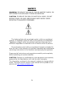
The lightning flash with arrowhead symbol, within an equilateral
triangle, is intended to alert the user to the presence of uninsulated
"dangerous voltage" within the product's enclosure that may be of
sufficient magnitude to constitute a risk of electric shock to persons.
The exclamation point within an equilateral triangle is intended to
alert the user to the presence of important operating and maintenance
(servicing) instructions in the literature accompanying the appliance.
Please read all instructions and precautions carefully and completely
before operating your power amplifier.
CAUTION: Changes or modifications to this equipment not expressly
approved by the manufacturer will void the user's warranty.
The information contained in the manual is subject to change without
notice. The most current version of this manual will be posted on our
web site at http://www.violalabs.com.
3
Important Safety Instructions
Please read all instructions and precautions carefully and completely
before operating your Viola Audio Labs power amplifier.
1. ALWAYS disconnect your entire system from the AC mains
before connecting or disconnecting any cables, or when cleaning
any component.
2. This product must be terminated with a three-conductor AC
mains power cord which includes an earth ground connection. To
prevent shock hazard, all three connections must ALWAYS be
used.
3. AC extension cords are not recommended for use with this
product.
4. NEVER use flammable or combustible chemicals for cleaning
audio components.
5. NEVER operate this product with any covers removed.
6. NEVER wet the inside of this product with any liquid.
7. NEVER pour or spill liquids directly onto this unit.
8. NEVER block air flow through ventilation slots or heatsinks.
9. NEVER bypass any fuse.
10. NEVER replace any fuse with a value or type other than those
specified.
11. NEVER attempt to repair this product. If a problem occurs,
contact your Viola Audio Labs retailer or factory.
12. NEVER expose this product to extremely high or low
temperatures.
13. NEVER operate this product in an explosive atmosphere.
14. ALWAYS keep electrical equipment out of the reach of children.
15. ALWAYS unplug sensitive electronic equipment during lightning
storms.
4
INTRODUCTION
Thank you for choosing the Viola Bravo Reference Amplifier. We
have designed and manufactured this exciting product utilizing the
latest techniques and the best materials available. Our goal is to
provide you with the highest quality listening pleasure available.
UNPACKING
Under no circumstances should you consider unpacking your
amplifier without adequate assistance as both personal injury and
damage to the product is likely unless you follow the procedures listed
below.
Your new VIOLA Bravo Power Amplifier is heavy—the shipping
weight of the Bravo is about 260 pounds (118 kg). We recommend
you use two or three people to unpack these amplifiers safely.
Do not attempt to lift your power amplifier from its packing carton
alone. Never attempt to lift your power amplifier while bending from
the waist. Always stand as straight as possible and use your leg
muscles to lift your amplifier.
After unpacking your Bravo power amplifier, keep all packing
materials for future transport. In the event that you need to ship your
amplifier, only the original, purpose-designed shipping carton is
acceptable. Any other method of shipping this heavy product will
almost certainly result in damage to the amplifier—damage that would
not be covered by the warranty.
Please inspect your amplifier for any obvious damage due to
shipping. If you discover any problems, contact your VIOLA dealer
immediately so an appropriate freight claim can be made.
Although your VIOLA Bravo power amplifier delivers outstanding
performance straight out of the box, you should expect to hear it
continue to improve as it reaches its normal operating temperatures
and its various components "break-in." It has been our experience that
the greatest changes occur within the first 25-50 hours, but that the
amplifier will continue to improve in sound quality for about 300 hours,
after which time it remains quite constant.
5
The only exception to this rule is if power is removed from the unit,
allowing it to cool down. This can occur due to: extended power
outages, unplugging the amplifier from the wall during a vacation; or
by leaving the amplifier in sleep mode rather than in standby. In these
cases you should expect a brief warm-up period before the amplifier's
sound quality is at its best. (Fortunately, you will never have to repeat
the full 300 hour break-in period.)
PLACEMENT CONSIDERATIONS
For your protection, review "Important Safety Instructions" above
before you install your amplifier.
Your VIOLA Bravo power amplifier is specifically designed to
accommodate a wide range of installation options. These amplifiers
may be placed on the floor, near the loudspeakers they drive. They
may also be located on shelves provided the shelves are sturdy
enough to bear the weight of the amplifier and have sufficient room for
proper ventilation. The sophisticated ventilation system employed by
the Bravo power amplifier will maintain optimal operating
temperatures in the output stage of the amplifier even when they are
stacked one above another.
However, if you have a choice in your design, locating each amplifier
near its respective loudspeaker is usually best. This approach
minimizes the length of the speaker wires, and necessitates longer
interconnecting cables from the preamplifier to the power amplifier.
The advantage to this strategy lies in the fact that the interconnecting
cables carry low-current signals that are more readily transmitted over
distances with great accuracy than are the necessarily high current
signals required by loudspeakers.
Note that adequate clearance for the AC cord and connecting signal
cables must be left behind your amplifiers. We suggest leaving at least
six inches (15 cm) of free space behind your amplifier so all cables
have sufficient room to bend without crimping or undue strain.
The Bravo power amplifier was designed to use both active and
passive cooling strategies. This highly efficient system features a
forced air cooling system to maintain optimal operating temperatures
under a wide range of conditions. This combination of passive and
active cooling is accomplished by fans running in conjunction with an
efficient system of heat sinks. Two ultra low-noise fans provide cooling
6
from side to side in the amplifier. If you look closely, you will see
crosscuts in the side plates of the amplifier. These cutouts provide the
air intake and exhaust for the forced-air cooling system. The fans’
superior engineering and ball-bearing construction allow them to run
extremely quietly. Most people will never notice them. The only time
you are likely to hear them is when you first turn the volume off after
a prolonged period of extremely high volume listening.
Regardless of where you choose to locate your amplifier, we advise
locating the amplifier near the floor and well away from sensitive lowlevel components. The Bravo power amplifier dissipates approximately
350 watts of energy as heat when on and at idle (no input signal). It is
therefore normal and perfectly safe for them to run somewhat warm.
Mechanical drawings are included in this manual to facilitate special
installations where necessary (see "Dimensions" at the end of this
manual).
SPECIAL DESIGN FEATURES
Congratulations on your purchase of a BRAVO Reference Amplifier
by Viola Audio Labs. While your new amplifier is straightforward in
everyday use, it includes several design features that are responsible
for its outstanding performance. In particular, your new power
amplifier defies the accepted wisdom that it is impossible to design a
large, powerful amplifier that also has all of the finesse of the finest
smaller amplifiers. A few of the technical highlights that make this
possible are given below.
Power Supply
The Bravo power amplifier used as a two box set is a stereo
amplifier with separate power supply. The separate power supply
assures complete freedom from electro-magnetic interference (EMI)
produced by the electromagnetic power supply components, i.e. the
power transformer and inductor (or choke).
The inductor (choke) input filter power supply design was chosen
because it produces far less EMI than conventional capacitor input
systems. The inductor (choke) input filter system greatly reduces the
electrical stress placed on the power supply components. Therefore,
7
this greatly increases the life span and reliability of the power supply
components. Capacitor lifespan in particular can be increased by at
least an order of magnitude. The virtual elimination of the high peak
ripple currents also minimizes intermodulation distortion on the power
supply “rails” and ground returns.
Additional power factor (PF) correction circuitry increases the PF
from .9 (typical for “choke” input supplies) to .96 (a power factor of 1
[unity] is considered ideal). The power supply utilizes large,
conventional components instead of a switching power supply because
they can operate at power levels several times their continuous power
ratings for longer periods. Given the duty cycles found in even the
most demanding music, large conventional magnetic components can
be used in audio power amplifiers whose continuous sine wave power
ratings would otherwise require a switching power supply rated at 3
times that of the conventional type. *
* Note: This duty cycle concept has nothing to do with so called
“music power”. FTC regulations were issued in the early 1970s to
standardize power ratings. These requirements include a
preconditioning of 1 hour operation at 1/3 rated power output after
which the amplifier is expected to be able to produce its full rated
power at any frequency within the rated bandwidth at a THD level of
no more than the manufacturer’s rated THD with all channels driven
together. This FTC rating approach was in fact a reaction to the
infamous “music power” rating system which at best represented the
amount of power an amplifier could deliver for a fraction of a second!
Actual music can demand sustained full power levels for up to 30
seconds.
The conventional magnetic supply used for this amplifier does not
utilize high frequency switching and therefore is devoid of any high
frequency noise. It offers much higher reliability and does not have to
be derated nearly as much as an equivalent switching power supply for
a given ambient temperature.
Each amplifier’s large, robust power supply includes a high
capacity, low noise toroidal transformer and inductor. Specifically, the
supply uses a 2kVA transformer with 320,000 mF total capacitance.
Four large, low ESR ("Equivalent Series Resistance") capacitors
(80,000 mf each) are located in the amp chassis. They are designed to
minimize the buss length to the output stages for optimum decoupling
of the supply lines.
Heavy oxygen-free copper bus bars enhance the efficiency of
power distribution within the amplifier and eliminate variances
8
introduced by wiring harnesses, etc. more commonly found in high
performance amplifiers. High frequency power supply bypass is
accomplished on individual PC boards with capacitors of several film
types. The resulting uniformly low power supply impedance seen by
the various circuits within the amplifier lays the foundation for both the
massive power and the extraordinary finesse that characterizes the
Bravo power amplifier.
Balanced design
A truly balanced input topology eliminates the need for an input
buffer amplification stage and allows the first stage differential
amplifier to be driven directly by the source. Matched impedances are
presented to the source and both signals travel through identical
circuit paths. Painstaking attention to layout of the amplifier was
essential to minimize magnetic field distortions possible with such a
massive power delivery system, including careful mirror-imaging of
circuits to cancel magnetic fields. A balanced input signal remains
balanced throughout the voltage gain stages.
True Voltage Source
Your new amplifier operates as a virtually perfect textbook case of
"voltage sources." This is to say that they will maintain whatever the
appropriate voltage might be at any moment (given the demands of
the music, and within the rated voltage output of the amplifier),
without any particular regard for the current demands of the
loudspeaker. Because of this "voltage source" characteristic, the
amplifiers double their power output every time the loudspeaker
impedance is cut by half. For example, the Bravo power amplifier’s
continuous rated power is 350 watts per channel at 8 Ohms; 700 watts
per channel at 4 Ohms; 1400 watts per channel at 2 Ohms—assuming
the electrical circuit in the wall can support these extraordinary power
levels. A continuous 2 Ohm test of the BRAVO at maximum power
requires over 25 amperes at 120V. (The laws of physics refuse to be
cheated. Long-term, you cannot deliver more power into the speaker
than you can pull from the wall.) Forty TO-3P output transistors are
distributed in the heat sinks of the Bravo power amplifier to conduct
and control the flow of its remarkable power capabilities to the
loudspeaker. There are twenty matched, complementary pairs of
output transistors in each channel of the amplifier.
No known high quality loudspeaker can absorb the continuous full
power capability of the Bravo (nor would you want to be present in the
9
room were you to find one that could do so). However, many high
quality loudspeakers may require rather extreme power levels on a
short term basis when reproducing music at realistic levels. Your new
amplifier can answer these needs with impunity, without any power
supply "sag" and without altering its sonic performance in any way.
The resultant imperturbable nature of these amplifiers is reflected in
the authority and control with which they reproduce music. Your
selection of any particular model depends only on the maximum power
you need, based on your loudspeakers, listening room, and listening
habits. Viola produces a line of loudspeakers that are designed to
match the Bravo amplifier. Ask your dealer about them.
Extensive Protection
Your new power amplifiers will shut themselves down if they sense
any of a number of fault conditions that could cause damage to either
themselves or to your loudspeakers. These fault conditions include:
• the presence of DC (direct current) at the output
• demand for excessive current (indicating a short circuit) at the
output
• either over-voltage or under-voltage conditions on the AC mains
• unsafe operating temperatures in any of several critical areas
within the amplifier.
In the case of either significant DC offset or an over-current
condition, the amplifier will shut down to protect itself and your
speakers. To restore normal operation, remove the cause of the fault
and cycle power (e.g., the AC mains power button).
If the AC mains voltage it either too high or too low for safe
operation, the amplifier will automatically shut down. The amplifier will
not turn back on until the AC mains voltage is again "legal" for normal
operation. As an example, a 120V unit will operate between
approximately 90-140V; a 240V unit will operate between
approximately 180-280V. Outside these generous limits, the amplifier
will shut off. Once the fault condition is removed, the amplifier can
again be turned on.
If the amplifier manages to become overheated despite the
innovative cooling system, it will once again shut down. Once the fault
condition is removed, the amplifier can again be turned on. In
addition, the AC input to each transformer is fused to protect against
excessive current conditions such as driving shorted outputs. Inrush
limiting prevents premature aging of power supply components during
10
power-up, and switches off-line once the power supply has been
charged.
Finally, your amplifier incorporates a controlled clipping circuit that
prevents the output devices from saturating. The harsh high frequency
harmonics generated by hard-clipped output devices are avoided by
the wave shaping action of this controlled clip circuitry.
Cooling System
The cooling system for your amplifier includes both fans and heat
sinks that use both active (fan-driven) and passive (convection)
cooling to ensure maximum performance and reliability.
Your amplifier includes two ultra quiet fans that maintain a uniform
temperature in all output devices. Located at the right side of the heat
sink assembly, they provide cooling to avoid destructive conditions
caused by inadequate ventilation or unusually high ambient
temperatures.
11
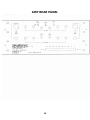
AMP REAR PANEL
12
SUPPLY REAR PANEL
Caution! Turn the volume on your preamplifier all the way
down before attempting to connect anything to your Bravo
power amplifier.
1. Rear Panel Handles
Please use these handles to make unpacking and moving your new
amplifier around both safer and more convenient. Have help available
for the initial unpacking and placement, as these amplifiers are quite
heavy. As with anything this massive, proper care should be taken to
avoid injury.
2. Speaker Binding Posts
Bravo power amplifiers are equipped with custom made, goldplated, high-current binding posts for output termination to a
loudspeaker system. To take full advantage of the amplifier's sonic
quality, we recommend using high-quality speaker cable such as
VIOLA Jazz cable; please see your VIOLA dealer for details.
13
Caution!
•
•
•
NEVER connect a power amplifier's output terminals to
any device other than a loudspeaker.
NEVER short -circuit the amplifier's output terminals.
NEVER connect the output terminals of one amplifier to
the output terminals of another amplifier unless connecting
for bridge mode operation (see Bridged Operation below).
Caution! There are two recommended methods for connecting
speaker cables to your amplifier. A high-quality spade lug or
hook lug, soldered to the cable (or crimped with extremely high
pressure), is best.
Spade lug
•
•
Hook lug
Connect a + (positive or red) output post of the amplifier
to the + (positive or red) input terminal of the appropriate
loudspeaker.
Connect a - (negative or black) output post of the amplifier
to the - (negative or black) input terminal of the
appropriate loudspeaker.
Caution!
•
•
DO NOT OVERTIGHTEN the binding posts on your
amplifier! The unique design of these posts gives far more
leverage than traditional posts. You will achieve tight,
high-contact pressure connections with only modest fingertightening, and without having to resort to special tools.
DO NOT FORCE the nut over a bent or oversized
connector, as this may damage the binding post. If your
connectors obstruct the turning of the nut, slide the
connectors into place when the binding post opening is a
snug fit; then apply a final quarter-turn as needed to
tighten the connection.
3. Balanced Audio Input
Bravo will accept a signal from a preamplifier with balanced
outputs via a high quality XLR or Fischer connector.
14
The pin assignments of the Bravo amplifier XLR-type female
chassis input connector is
Pin 1: Signal ground
Pin 2: Signal + (non-inverting)
Pin 3: Signal - (inverting)
Connector ground lug or case: chassis ground
These pin assignments are consistent with the standards adopted by
the Audio Engineering Society. Refer to the operating manual of your
balanced-output preamplifier to verify- that the pin assignments of its
output connectors correspond to your Bravo power amplifier. If not,
wire the cables so that the appropriate output pin connects to the
equivalent input pin.
4.
AC mains cord and AC mains switch
IEC standard power cords are used in the Bravo power amplifier.
Plug the cord into the high-current IEC outlet provided, and then into a
suitable wall outlet.
Your new Bravo power amplifier has been safety-tested and is
designed for operation with a three-conductor power cord. Do not
defeat the "third pin" or earth ground of the AC power cord.
Two fuses are located at the rear of the Bravo power amplifier. The
protection circuitry has been designed such that only a catastrophic
failure would cause these fuses to blow. As a result, if you suspect that
your AC fuses have blown, disconnect your amplifier from the AC
mains and check them.
Potentially dangerous voltages and current capabilities exist within
your power amplifier, even when disconnected from AC mains. Do not
attempt to open any portion of the amplifier's cabinet. There are no
user-serviceable parts inside your power amplifier. All service of this
product must be referred to a qualified VIOLA dealer or distributor.
15
MONO OPERATION
The Bravo Amplifier is a 2 channel stereo amplifier that can be
converted to a mono amplifier in one of two ways, Internal Bridge
Mode or Internal Parallel Mode. Internal Bridge mode is better suited
for high impedance loudspeakers (4 ohms and above) that require
more voltage. Internal Parallel Mode is better suited for lower
impedance loudspeakers (4 ohms and below) requiring more current.
INTERNAL BRIDGE MODE:
Switch settings:
1) STEREO-MONO/PARALLEL-MONO/BRIDGE switch: Set to
MONO/BRIDGE
2) PHASE switch: Set to 180 degrees
Input / Output setup:
1) Use Left channel input for signal input
2) Use Left channel “H” output terminals for plus (±) output to
speaker
3) Use Right channel “H” output terminal for minus (-) output to
speaker
INTERNAL PARALLEL MODE:
Switch settings:
1) STEREO-MONO/PARALLEL-MONO/BRIDGE switch: Set to
MONO/PARALLEL
2) PHASE switch: Set to 0 degrees
Input / Output setup:
1) Use Left channel input for signal input
2) Install parallel jumpers between center “H” Left and Right
terminals and center “L” Left and Right terminals
3) Use remaining Left and/or Right channel output terminals to
speaker. “H” is plus (+) and “L” is minus (-)
16
BRIDGED OPERATION
Bridging is the process of converting the left and right channels of your
amplifier to act as if it was a single, much larger, one channel
amplifier. To play music from both channels (stereo) you would need a
second amplifier in bridged mode. Bridging permits you to increase the
amount of power you send to each channel by almost four times.
Bridging is useful with low sensitivity, high-impedance speakers that
require high voltage.
Bravo is a 350 w/ch two channel power amplifier consisting of two
chassis. Supply chassis features inductor (choke) input. Amplifier
chassis consists of two half-bridge audio sections permitting amplifier
to be configured as:
• A stereo amp rated at 350 w/ch (a two box set);
• A half-bridge parallel mode mono block rated at 400 w/ch (a four
box set) recommended for use with low impedance speakers (4
Ohms to 1 Ohm)-rated at 1000 w/ch into 4 Ohms, 1200 w/ch
into 2 Ohms and 1600 w/ch into 1 Ohm; used in full bridge
mode (an 8 box set) will produce 3600 w/ch into 1 ohm;
• A bridge-mode mono block rated at 1200 w/ch into 8 Ohms (a
four box set) and 1600 w/ch into 4 Ohms.
BRIDGE OPERATION
NOTE: Two Bravo amplifier chassis can be bridged together if each
amplifier is set to Internal Parallel Mode. For setup purposes we will
designate one amplifier amp A and the second amplifier amp B.
Setup:
1) Set each amplifier to Internal Parallel Mode
2) Use Left channel input of amp A for signal input
3) Connect input Bridging cable provided in your Bridging Kit, from
amp A to Left channel input of amp B
4) Use Left channel “H” output terminals of amp A as your plus (+)
speaker out
5) Use Left channel “H” output terminal of amp B as your minus (—)
speaker out
6) Connect Left channel “L” output terminals of amps A&B together
with the jumper provided in your Bridging Kit.
7) Connect DC Supply harness provided in your Bridge Kit between
DC inputs of amp A and amp B. Observe proper color codes.
17
WIRING AND BIAMPLIFICATION
SINGLE WIRE CONFIGURATION
Single-wiring uses one amplifier channel to power each loudspeaker.
A single wire carries the high frequency (HF) and low frequency (LF)
information. Jumpers connect the HF and LF sections of the speaker’s
crossover network at the loud speaker.
BI-WIRE CONFIGURATION
Bi-wiring also uses one amplifier channel to power each loudspeaker.
However separate wires carry the high frequency and low frequency
information. This wiring method is considered superior to single-wiring
because it reduces the likelihood of the two sections of the band
interacting and creating audible distortion. Since the bi-wire has twice
as much conductor as the single-wire the common or shared
resistance of the cable is reduced.
BI-AMPLIFICATION
Bi-amplification uses two stereo amps to power a single pair of
loudspeakers. One amplifier is used for each speaker and one channel
in each amplifier is used for each of the high and low frequencies of
each speaker. Bi -amplification extends the benefits of bi -wiring into
the amplifier. Not only does it reduce interaction in the cable but in the
amplifier channels as well.
CARE & MAINTENANCE
To remove dust from the cabinet of your amplifier, use a feather
duster or a lint -free soft cloth. To remove dirt and fingerprints, we
recommend a non-abrasive glass cleaner and a soft cloth. Do not use
alcohol or any other flammable liquid. Dampen the cloth with the
cleaner first and then lightly clean the surface of the amplifier with the
cloth. Do not use excessive amounts of cleaner that might drip off the
cloth and into the amplifier.
18
Caution! At no time should liquid cleaners be applied directly
to the amplifier, as direct application of liquids may result in
damage to electronic components within the unit.
TROUBLESHOOTING
In general, refer any service problems to your VIOLA dealer. Before
contacting your dealer, however, check to see if the problem is listed
here. If it is, try the suggested solutions. If none of these solves the
problem, contact your VIOLA dealer.
1.
No sound and the LED is not lit? Check the following:
The amplifier is not plugged into the AC mains, or the AC mains
are down (circuit breaker, fuse).
• A power loss had occurred, requiring restart.
• The front panel AC mains switch is in the off position.
• One or more fuse is blown in your amplifier (contact your VIOLA
dealer: no user-serviceable components ins ide).
•
2.
No sound and the LED is lit? Check the following:
Check your wiring; the amplifier is on and operational, but signal
is not getting through.
• Check that the preamplifier and the source are on.
• Check the volume control to be sure that it is set high enough to
hear.
•
3.
The amplifier keeps shutting off?
Disconnect both the input signal and speaker cable from the
amplifier and try restarting the amplifier. If the amplifier comes on
(LED on), something is wrong with either the input (e.g., DCO from
the preamp) or the output (e.g., shorted speaker wires). Turn off,
reconnect only the speakers, and try again. If everything is okay,
turn off and connect only the preamp. You should be able to isolate
the source of the problem.
OBTAINING SERVICE
We take great pride in our dealers. Experience, dedication, and
integrity make these professionals ideally suited to assist with our
customers' service needs.
19
If your VIOLA component must be serviced, please contact your
dealer. Your dealer will then decide whether the problem can be
remedied locally, or whether to contact the VIOLA factory for further
service information or parts, or to obtain a Return Authorization. The
VIOLA Technical Services Department works closely with your dealer
to solve your service needs expediently.
Important!
Return authorization must be obtained from VIOLA’S Technical
Services Department BEFORE a unit is shipped for service.
It is extremely important that information about a problem be
explicit and complete. A specific, comprehensive description of the
problem helps your dealer and the VIOLA Technical Services
Department locate and repair the difficulty as quickly as possible. A
copy of the original bill of sale will serve to verify warranty status.
Please include the copy with the unit when it is brought in for warranty
service.
Warning!
All returned units must be properly packaged (preferably in their
original packing material), and the proper return authorization
numbers must be marked on the outer carton for identification. If the
packaging to protect the unit is, in our opinion or that of our dealer,
inadequate to protect the unit, we reserve the right to repackage it for
return shipment at the owner's expense. Neither VIOLA nor your
dealer can be responsible for shipping damage due to improper (that
is, non-original) packaging.
Your dealer can order a new set of shipping materials for you if you
need to ship your component and no longer have the original
materials. There will be a charge for this service. We strongly
recommend saving all packing materials in case you need to ship your
unit some day.
WARRANTY
Products of Viola Audio Labs are warranted to be free of defects if
used under normal conditions for a period of five years from the date
of shipment from the factory. This warranty is transferable to
subsequent owners for the balance of the warranty period. Purchasers
20
of previously owned equipment should contact the factory to
determine the balance of the warranty period.
SERVICE
If you believe your VIOLA equipment is not functioning properly,
please call your dealer. If you need to return your component, you will
be given a Return Authorization number (RA#) by the factory. This
number must appear on the outside of the shipping box. Returns
without RA# will not be accepted. Returns received in non-standard
boxes will be replaced with new packing at the owner’s expense. If you
need replacement packaging, please contact your dealer or the
factory. Return Authorization numbers (RA#) may be obtained from
your dealer or by calling the factory or email to [email protected] .
Viola will repair, under the warranty, any defect in the product
except when caused by abusive conditions. Any defect in the product
during the first year shall be repaired for the customer by the
distributor. At VIOLA’S discretion, or if the distributor is unable to
perform the repair, the unit may be returned to the factory for service,
at Viola’s expense, using a factory approved freight carrier. After
repair, the unit will be returned via the same carrier or an equivalent
service.
During years 2 to 5, if the distributor is unable to perform the
warranty repairs, VIOLA will pay return from the factory by approved
carrier provided the unit was shipped to the factory with freight
prepaid. VIOLA will not pay freight if units are returned without a
Return Authorization Number (RA#). VIOLA will not pay the freight if
units are found to be in perfect working order. For non-warranty
repairs it is expected that the customer will pay for shipping both
ways.
Any specific repairs or modifications effected by the factory or
authorized service facility shall be guaranteed for 100% parts and
labor for the unexpired portion of the warranty period or one year,
whichever is longer.
LIMITS
Any unauthorized modifications, repairs or tampering, and/or any
indications of obvious owner abuse, negligence or improper usage, as
determined by VIOLA, will result in the voiding of the warranty.
21
There is no other express warranty on this component. This warranty
shall not extend beyond the stated warranty period. No responsibility
is assumed for incidental or consequential damages.
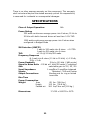
SPECIFICATIONS
Class of Output Operation:
AB2
Power Rating:
350 watts continuous average power into 8 ohms; 20 Hz to
20 kHz with both channels driven at less than 0.1% THD
1200 watts continuous average power into 8 ohms when
configured in Bridged Mode
IM Distortion (SMPTE)
1 watt to 300 watts into 8 ohms <0.075%
1 watt to 450 watts into 4 ohms
THD
<0.1% @ 20 kHz/350 watts
Frequency Response
@ 1 watt into 8 ohms (10 Hz to 20 kHz) +/-0.15 db;
100k <-3 db
Power Bandwith
5 Hz to 100 kHz (-3dB points)
Signal to Noise Ratio -105 db at 1 kHz/350 watts; C weighted
Gain
switchable gain to 23 / 26 / 29
Input Impedance
1 megOhm/1 megOhm balanced
Inputs:
Balanced - XLR and Fischer
Output Connections:
Binding post for ring or forked
terminals
Rise Time
Power Consumption
Weight
Amp
85 lbs. (38.6 kg.)
Supply
125 lbs. (56.8 kg.)
Packed set
260 lbs/2 box set (118 kg.)
Dimensions:
17.6”W x 9.625”H x 26”D
22
DIMENSIONS
FRONT PLATE
_
|
|
9.625”*
|
|
|-----------------17.58-----------------|
*ADD .75” FOR FEET
REAR PLATE
_
|
|
8.79”
|
|
|----------------16.74----------------|
BOTTOM PLATE
_
|
|
|
|
16.74”
|
|
|
|
|--------------------------26.03*--------------------------|
*ADD 1.75” TO REAR AND 1” TO FRONT FOR CLEARANCES
23
FRONT