1
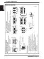
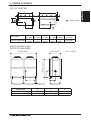
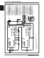
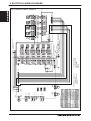
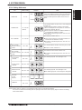
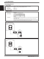
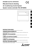
DEDICATED OUTSIDE AIR SYSTEM WITH REHEAT
1. GENERAL DESCRIPTION............................................................................................................................ PEFY-AF-R-2
2.SPECIFICATIONS......................................................................................................................................... PEFY-AF-R-3
3. EXTERNAL DIMENSIONS............................................................................................................................ PEFY-AF-R-7
4. CENTER OF GRAVITY............................................................................................................................... PEFY-AF-R-11
5. ELECTRICAL WIRING DIAGRAMS............................................................................................................ PEFY-AF-R-12
6. SOUND PRESSURE LEVELS AND NC CURVES..................................................................................... PEFY-AF-R-17
7. FAN CHARACTERISTIC CURVES............................................................................................................. PEFY-AF-R-19
8. CAPACITY TABLES.................................................................................................................................... PEFY-AF-R-20
8-1. Correction by Temperature................................................................................................................ PEFY-AF-R-20
8-2. Cooling Capacity with PURY-P120TJMU/YJMU............................................................................... PEFY-AF-R-21
8-3. Heating Capacity with PURY-P120TJMU/YJMU............................................................................... PEFY-AF-R-21
8-4. Correction by Refrigerant Piping Length........................................................................................... PEFY-AF-R-21
8-5. Correction at Frost and Defrost......................................................................................................... PEFY-AF-R-22
8-6. Operation Temperature Range.......................................................................................................... PEFY-AF-R-22
9. SYSTEM DESIGN....................................................................................................................................... PEFY-AF-R-23
9-1. Electrical Work.................................................................................................................................. PEFY-AF-R-23
9-2. M-NET Control.................................................................................................................................. PEFY-AF-R-25
9-3. Piping Design.................................................................................................................................... PEFY-AF-R-29
PEFY-AF1200CFMR (Sept. 2010)
PEFY-AF-R-1
PEFY-AF1200CFMR
PEFY-AF1200CFMR
1. GENERAL DESCRIPTION
PEFY-AF1200CFMR
Unit Configuration
Model
PEFY-AF1200CFMR
PURY-P120TJMU-A(-BS)
Outdoor unit
PURY-P120YJMU-A(-BS)
CMB-P106NU-G
BC Controller
CMB-P108NU-G
Operating Temperature Range
Indoor unit inlet air
temperature
Outdoor unit inlet air
temperature
PEFY-AF-R-2
Cooling
Heating
50 to 95°FW.B. (109°FD.B.)
-4 to 60°FW.B.
10 to 35°CW.B. (43°CD.B.)
-20 to 15.6°CW.B.
50 to 109°FD.B.
-4 to 60°FW.B.
10 to 43°FD.B.
-20 to 15.6°CW.B.
PEFY-AF1200CFMR (Sept. 2010)
2. SPECIFICATIONS
BTU / h
kW
kW
A
BTU / h
kW
kW
A
Power input
Current input
Heating capacity
(Nominal)
Power input
Current input
External finish
in.
mm
lbs (kg)
External dimension H x W x D
Net weight
Heat exchanger
FAN
Type x Quantity
in.WG
Pa
External static pressure
in.WG
Pa
Motor type
Driving mechanism
Airflow rate
cfm
Liquid (R410A)
Gas (R410A)
in. (mm)
in. (mm)
in. (mm)
L/s
dB <A>
dB <A>
Sound pressure level (Low-Mid-High)
(measured in an anechoic room)
Insulation material
Air filter
Protection device
Refrigerant control device
Connectable outdoor unit
Diameter of refrigerant pipe (O.D.)
Diameter of drain pipe
Notes:
PEFY-AF1200CFMR
1-phase 208/230V 60Hz
112,000
32.8
0.66/0.78
3.19/3.45
61,400
18
0.66/0.78
3.19/3.45
Galvanized
18-9/16 x 49-1/4 x 55-1/8
470 x 1,250 x 1,400
309 (140)
Cross fin (Aluminium fin and copper tube)
Sirocco fan x 2
0.28-0.48-0.80 (208V)
70-120-200
0.52-0.72-0.96 (230V)
130-180-240
Single phase induction motor
Direct-driven
PEFY-AF1200CFMR
Model
Power source
Cooling capacity
(Nominal)
1,200
566
36-38-41 (208V)
39-41-43 (230V)
Polyethylene foam, Polyurethane foam, Polystyrene foam
Field supplied
Fuse
LEV
PURY-P120TJMU-A(-BS), PURY-P120YJMU-A(-BS)
3/8 (9.52) Brazed
7/8 (22.2) Brazed
O.D. 1-1/4(32) x 2
1. Standard capacities are the maximum capacities that are obtained in the following conditions:
Air conditions : cooling : indoor 87°FDB/80°FWB (30.5°CDB/26.7°CWB) outdoor 87°FDB( 30.5°CDB) heating: indoor
32°FDB (0°CDB) outdoor 32°FDB (0°CDB)/28°FDB(-2°CWB), Connected outdoor unit is PURY-P120TJMU/YJMU-A(-BS)
Piping length: 24.6 feet (7.5m) Height difference : 0 feet (0m)
2. This value shows the data per unit.
3. Sound pressure level is the data that was obtained in anechoic room by the following conditions:
The measuring point is 4.9feet (1.5m) from the bottom of the unit that has 6.6feet (2m) outlet duct and 6.6feet (2m) intake duct.
4. When combining the drain pipes, ensure that collected pipes are 3-15/16inch(10cm) lower than the unit body's drain port.
5. Install BC controller in a location where refrigerant flow sound emitted by the unit will not disturb the neighbors.
(For use in quiet environments with low background sound, position the BC controller at least 16.4feet(5m) away from any indoor units.)
6. When connecting the indoor unit to the BC controller, the optional twinning pipe shall be installed.
(Refer to Figure1, Figure2, and Table1)
7. The choice of indoor unit operation mode is limited to auto mode.
Piping Connection
Indoor unit
[Figure1]
Fan motor
[Figure2]
Gas :ø7/8in.[ø22.2]
Liquid:ø3/8in.[ø9.52]
Reheat Main
Number of connection pipe of BC
Outdoor model
PURY-P120TJMU/YJMU-A(-BS)
Intake air
Field supplied
Twining pipe
(CMY-R160-J)
Twining pipe
(CMY-R160-J)
BC controller
[Table1]
Main Reheat
4
2
4-3/4in.[120mm]
Gas :ø3/4in.[ø19.05]
Liquid:ø3/8in.[ø9.52]
PEFY-AF1200CFMR (Sept. 2010)
PEFY-AF-R-3
PEFY-AF1200CFMR
2. SPECIFICATIONS
Model
Power source
Cooling capacity (Nominal) *1 (208-230)
Power input
Current input
Temp. range of cooling Outdoor
Heating capacity (Nominal) *2 (208-230)
Power input
Current input
Temp. range of heating Outdoor
Sound pressure level (measured in
anechoic room)
Liquid pipe
Refrigerant
piping diameter
Gas pipe
Type x Quantity
BTU / h
kW
A
D.B.
BTU / h
kW
A
W.B.
PURY-P120TJMU-A(-BS) for use with PEFY-AF1200CFMR
3-phase 3-wire 208 / 230V ±10% 60Hz
112,000
11.9 (Estimated) *3
30.8 / 27.8 *3
23~115°F(-5~46°C)
61,400
7.4 (Estimated) *3
33.9 / 30.7 *3
-4~60°F(-20~15.5°C)
dB <A>
60.0
3/4"(19.05) Brazed
1-1/8"(28.58) Brazed
Propeller fan x 2
cfm
10,600
300
Airflow rate
m3 / min
L/s
5,000
Fan
Control, Driving mechanism
Inverter-control, Direct-driven by motor
Motor Output
kW
0.92 + 0.92
External static pressure *4
0 in.WG (0 Pa) *4
Type x Quantity
Inverter scroll hermetic compressor x 1
Manufacturer
AC&R Works,MITSUBISHI ELECTRIC CORPORATION
Operating Range
15-100%
Compressor
Starting method
Inverter
Case heater
kW
0.045(230V)
Lubricant
MEL32
External finish
Pre-coated galvanized steel sheet (+powder coating for -BS type) *5 <MUNSELL 5Y 8/1>
In.
64-31/32" x 68-29/32" x 29-15/16"
External dimension H x W x D
mm
1,650 x 1,750 x760
High pressure protection
High pressure sensor,High pressure switch at 4.15MPa(601 psi)
Inverter circuit (COMP. / FAN)
Over-heat protection,Over-current protection
Protection
devices
Compressor
Over-heat protection
Fan motor
Thermal switch
Minimum Circuit Ampacity
A
49 / 46
Recommended Fuse/Breaker Size
A
50
Maximum Fuse Size
A
70 / 70
Type x original charge
R410A x 26lbs + 1 oz (11.8kg)
Refrigerant
Control
Indoor LEV and BC controller
Net weight
lbs (kg)
695(315)
Heat exchanger
Salt-resistant cross fin & copper tube
HIC circuit (HIC: Heat Inter-Changer)
Defrost method
Auto-defrost mode (Reversed refrigerant cycle)
External
WKB94T927
Drawing
Wiring
WKE94C375
Document
Installation Manual
Standard
attachment
Accessory
Details refer to External Drw
PEFY-AF1200CFMR Indoor Unit
PURY-P120TJMU-A(-BS) Outdoor Unit
System Components
Joint: CMY-R160-J
BC controller: CMB-P106,108NU-G
Details on foundation work, duct work, insullation work, electrical wiring, power source switch, and
other items shall be referred to the Installation Manual.
*3 For details on the electrical data needed for installing these units, see the R2-Series System Design
Remark
section.
*4 External static pressure is adjustable via dipswitch setting (0.12 in.WG, 0.24 in.WG / 30Pa, 60Pa).
*5 For information on standard anti-corrosion protection and -BS treatment, see the R2-Series System
Design section.
Notes:
PEFY-AF-R-4
In. (mm)
In. (mm)
1. Standard capacities are the maximum capacities that are obtained in the following conditions:
Air conditions : cooling : indoor 87°FDB/80°FWB (30.5°CDB/26.7°CWB) outdoor 87°FDB( 30.5°CDB) heating: indoor
32°FDB (0°CDB) outdoor 32°FDB (0°CDB)/28°FDB(-2°CWB), Connected outdoor unit is PURY-P120TJMU/YJMU-A(-BS)
Piping length: 24.6 feet (7.5m) Height difference : 0 feet (0m)
2. This value shows the data per unit.
3. Sound pressure level is the data that was obtained in anechoic room by the following conditions:
The measuring point is 4.9feet (1.5m) from the bottom of the unit that has 6.6feet (2m) outlet duct and 6.6feet (2m) intake duct.
4. When combining the drain pipes, ensure that collected pipes are 3-15/16inch(10cm) lower than the unit body's drain port.
5. Install BC controller in a location where refrigerant flow sound emitted by the unit will not disturb the neighbors.
(For use in quiet environments with low background sound, position the BC controller at least 16.4feet(5m) away from any indoor units.)
6. When connecting the indoor unit to the BC controller, the optional twinning pipe shall be installed.
(Refer to Figure1, Figure2, and Table1)
7. The choice of indoor unit operation mode is limited to auto mode.
PEFY-AF1200CFMR (Sept. 2010)
2. SPECIFICATIONS
BTU / h
kW
A
D.B.
BTU / h
kW
A
W.B.
dB <A>
60.0
In. (mm)
In. (mm)
3/4"(19.05) Brazed
1-1/8"(28.58) Brazed
Propeller fan x 2
10,600
300
5,000
Inverter-control, Direct-driven by motor
0.92+0.92
0 in.WG (0 Pa) *4
Inverter scroll hermetic compressor x 1
AC&R Works,MITSUBISHI ELECTRIC CORP.
15-100%
Inverter
0.045(230V)
MEL32
Pre-coated galvanized steel sheet (+powder coating for -BS type) *5 <MUNSELL 5Y 8/1>
64-31/32" x 68-29/32" x 29-15/16"
1,650 x 1,750 x760
High pressure sensor,High pressure switch at 4.15MPa(601 psi)
Over-heat protection,Over-current protection
Over-heat protection
Thermal switch
23
25
30
R410A x 26lbs + 1 oz (11.8kg)
Indoor LEV and BC controller
728(330)
Salt-resistant cross fin & copper tube
Auto-defrost mode (Reversed refrigerant cycle)
WKB94T935
WKE94C377
Installation Manual
Details refer to External Drw
PEFY-AF1200CFMR Indoor Unit
PURY-P120YJMU-A(-BS) Outdoor Unit
Joint: CMY-R160-J
BC controller: CMB-P106,108NU-G
Details on foundation work, duct work, insullation work, electrical wiring, power source switch, and
other items shall be referred to the Installation Manual.
*3 For details on the electrical data needed for installing these units, see the R2-Series System
Design section.
*4 External static pressure is adjustable via dipswitch setting (0.12 in.WG, 0.24 in.WG / 30Pa, 60Pa).
*5 For information on standard anti-corrosion protection and -BS treatment, see the R2-Series
System Design section.
cfm
m3 / min
L/s
Control , Driving mechanism
Motor output
kW
External static pressure
Type x Quantity
Manufacturer
Operating Range
Starting method
Case heater
kW
Lubricant
Air flow rate
Fan *3
Compressor
External finish
In.
mm
High pressure protection
Inverter circuit (COMP. / FAN)
Protection devices
Compressor
Fan motor
Minimum Circuit Ampacity (MCA)
A
Recommended Fuse/Breaker Size
A
Maximum Fuse Size
A
Type x original charge
Refrigerant
Control
Net weight
lbs (kg)
Heat exchanger
HIC circuit (HIC: Heat Inter-Changer)
Defrost method
External
Drawing
Wiring
Document
Standard attachment
Accessory
External dimension H x W x D
System Components
Remark
Notes:
PURY-P120YJMU-A(-BS) for use with PEFY-AF1200CFMR
3-phase 3-wire 460V ±10% 60Hz
112,000
11.9 (Estimated) *3
13.9 *3
23~115°F(-5~46°C)
61,800
7.4 (Estimated) *3
15.3 *3
-4~60°F(-20~15.5°C)
PEFY-AF1200CFMR
Model
Power source
Cooling capacity (Nominal) *1 (208/230V)
Power input
Current input
Temp. range of cooling Outdoor
Heating capacity (Nominal) *2 (208/230V)
Power input
Current input
Temp. range of heating Outdoor
Sound pressure level (measured in anechoic
room)
High pressure
Refrigerant piping
diameter
Low pressure
Type x Quantity
1. Standard capacities are the maximum capacities that are obtained in the following conditions:
Air conditions : cooling : indoor 87°FDB/80°FWB (30.5°CDB/26.7°CWB) outdoor 87°FDB( 30.5°CDB) heating: indoor
32°FDB (0°CDB) outdoor 32°FDB (0°CDB)/28°FDB(-2°CWB), Connected outdoor unit is PURY-P120TJMU/YJMU-A(-BS)
Piping length: 24.6 feet (7.5m) Height difference : 0 feet (0m)
2. This value shows the data per unit.
3. Sound pressure level is the data that was obtained in anechoic room by the following conditions:
The measuring point is 4.9feet (1.5m) from the bottom of the unit that has 6.6feet (2m) outlet duct and 6.6feet (2m) intake duct.
4. When combining the drain pipes, ensure that collected pipes are 3-15/16inch(10cm) lower than the unit body's drain port.
5. Install BC controller in a location where refrigerant flow sound emitted by the unit will not disturb the neighbors.
(For use in quiet environments with low background sound, position the BC controller at least 16.4feet(5m) away from any indoor units.)
6. When connecting the indoor unit to the BC controller, the optional twinning pipe shall be installed.
(Refer to Figure1, Figure2, and Table1)
7. The choice of indoor unit operation mode is limited to auto mode.
PEFY-AF1200CFMR (Sept. 2010)
PEFY-AF-R-5
PEFY-AF1200CFMR
2. SPECIFICATIONS
Model
Number of branches
Power source
Cooling
Heating
Cooling
Heating
Power input
(208/230)
Current (208/230)
CMB-P106NU-G
6
1-phase 208/230V 60Hz
0.086
0.040
0.41/0.37
0.19/0.17
kW
A
CMB-P108NU-G
8
---0.112
0.053
0.54/0.49
0.25/0.23
Galvanized steel plate
(Lower part drain pan :Pre-coated galvanized sheets + powder coating)
External finish
Connectable outdoor unit
Indoor unit capacity
connectable to 1
branch
kW
External dimension
HxWxD
in. (mm)
PURY-P120TJMU-A(-BS), PURY-P120YJMU-A(-BS)
Model P54 or smaller
( Use optional joint pipe combing 2 branches when the total unit capacity exceeds P55. )
( Use the reducer (standard accessory) when the indoor unit Model 18 or smaller is connected. )
11-3/16 x 25-17/32 x 17-1/32 (284 x 648 x 432)
Connectable outdoor unit
capacity
to P120
in. (mm) O.D.
Refrigerant piping
diameter
in. (mm) O.D.
Field drain pipe size
Net weight
in. (mm) O.D.
lbs (kg)
Accessories
Note:
To outdoor unit
High press. pipe
Low press. pipe
3/4 (19.05)
1-1/8 (28.58)
Brazed
Brazed
From BC Controller to PEFY-AF-CFMR Indoor Unit
Liquid pipe
Gas pipe
3/8 (9.52) Flare
5/8 (15.88) Flare
(1/2 (12.7) with attached reducer used, 3/4 (19.05)
(1/4 (6.35) with attached reducer used.)
and 7/8 (22.2) with optional joint pipe used.)
1-1/4 (32)
1-1/4 (32)
76 (34)
84 (38)
Drain Connection pipe
Drain Connection pipe
(with flexible hose and insulation)
(with flexible hose and insulation)
Reducer
Reducer
1. Installation/foundation work, electrical connection work, duct work, insulation work, power source switch,
and other items are not specified in this specifications.
2. The equipment is for R410A refrigerant.
3. Install this product in a location where noise (refrigerant noise) emitted by the unit will not disturb the
neighbors. (For use in quiet environments with low background noise,position the BC CONTROLLER at least
5m away from any indoor units.)
4. The data presented is based on a specific combination.
BC Controller to PEFY-AF1200CFMR
Main Coil Refrigerant Piping Dimensions
Reheat Coil Refrigerant Piping Dimensions
Liquid (High Pressure)
3/8” / 9.52 mm
3/8” / 9.52 mm
Gas (Low Pressure)
7/8” / 22.2 mm
7/8” / 22.2 mm
Indoor unit
Fan motor
Reheat Main
Intake air
Field supplied
Twining pipe
(CMY-R160-J)
Twining pipe
(CMY-R160-J)
BC controller
Number of Connection Pipes
Outdoor model
Main Reheat
PURY-P120TJMU/YJMU (-BS)
PEFY-AF-R-6
4
2
PEFY-AF1200CFMR (Sept. 2010)
PEFY-AF1200CFMR (Sept. 2010)
300 (11-13/16)
(Duct)
1 Gas pipe
ø22.2 (7/8)
6
4
95 (3-3/4)
3
25 (1)
100 (3-15/16)
ø9.52 (3/8)
2
4 Liquid pipe
Drain pump
1
ø22.2 (7/8)
7
3 Gas pipe
5
9
10 12
Control box
96 (3-13/16)
1450 (57-1/8)
1400 (55-1/8)
339 (13-3/8)
8
100 (3-15/16)
1338 (52-11/16) (Suspension bolt pitch)
100 (3-15/16)
350 (13-13/16)
2 Liquid pipe
ø9.52 (3/8)
170 (6-3/4)
170 (6-3/4)
524 (20-11/16)
10 (7/16)
25 (1)
30 (1-3/16)
13
11
1385 (54-9/16)
2x4-ø2.9 (1/8) hole
10 (7/16)
25(1)
10 (7/16)
Air
inlet
100x10=1000 (3-15/16x10=39-3/8)
50 (2)
1000 (39-3/8) (Duct)
2x3-ø3.4 (3/16) hole
115
(4-9/16)
1326 (52-1/4)
470 (18-9/16)
1325 (52-3/16) (Suspension bolt pitch)
23 (15/16)
50 (2)
1100 (43-5/16) (Duct)
(Duct)
400 (15-3/4)
35 (1-7/16)
2)
150
(5-1
50(
5/1
6)
110
0
Access door
6)
3 -5
/8)
Ceiling surface
Drain hose VP-25
<accessory>
)
Refrigerant piping brazing connection (Main Coil:gas)·······················
Refrigerant piping brazing connection (Main Coil:liquid)····················
Refrigerant piping brazing connection (Reheat Coil:gas)··················
Refrigerant piping brazing connection (Reheat Coil:liquid)················
Drain pipe (O.D.ø32(1-1/4)) (Spontaneous draining)·························
Drain pipe (O.D.ø32(1-1/4)) (Emergency draining)····························
Drain pipe (O.D.ø32(1-1/4))································································
Water filling port··················································································
Terminal block (Power source)···························································
Terminal block (Indoor/outdoor connecting)········································
Terminal block (Remote controller transmission)································
Knockout hole ø22 (1-1/8)(Power source wiring)·······························
Knockout hole ø22 (1-1/8) Indoor/outdoor connecting wiring
···
Remote controller transmission wiring
(
800
(31
-1/2
)
0(4
2-3
/1
6)
Access door
More than 800(31-1/2)
Required space for service and maintenance
(2
600
Note2
107
1
2
3
4
5
6
7
8
9
10
11
12
13
180±5(7-1/8±1/4)
Less than 300(11-13/16)
Make the access door at the appointed position properly
for service maintenance.
6)
3/1
-5/1
53 -
(43
0(
135
2)
50(
Note 1. Use M10 screw for the suspension bolt (field supply).
2. Keep the service space for the maintenance at the bottom.
75 (3)
100x9=900 (3-15/16x9=35-7/16)
50 (2)
Suspension bolt hole
4-14x30 (9/16x1-3/16) Slot
10 (7/16)
60 (2-3/8)
185 (7-5/16)
100x2=200
(3-15/16x2=7-7/8)
40 (1-5/8)
155 (6-1/8)
100 (3-15/16)
35 (1-7/16)
More than 20(13/16)
More than 20(13/16)
Air
outlet
395 (15-9/16)
1250 (49-1/4)
75 (3)
100x3=300
(3-15/16x3=11-13/16)
50 (2)
Less than 550(21-11/16)
2x11-ø2.9 (1/8) hole
PEFY-AF1200CFMR
Unit : mm(in)
PEFY-AF-R-7
PEFY-AF1200CFMR
2x10-ø2.9 (1/8) hole
3. EXTERNAL DIMENSIONS
23
(29/32)
130
(5-1/8)
(9-25/32)
X
70
76
(7-7/8)
200
(2-25/32) (3)
Y
1
2
(1-3/16)
3
4
30
60 (2-3/8)
Connection pipe of outdoor unit(High pressure)
(1-1/4)
248
(2-17/32) (4-1/16)
Connection pipe of outdoor unit(Low pressure)
(2-17/32) (4-19/32) (5-1/16)
64
116
128
Detail of X section
128
Drain piping
I.D.32 (1-1/4)
103
64
PEFY-AF1200CFMR (Sept. 2010)
255 (10-1/16)
12 (1/2)
5
14
6
7
8
9
10
60(2-3/8)XC=D
B
11
(Lifting bolt pitch)
A
Detail of Y section
(9/16)
12
13
14
Control box
15
16
200
CMB-P106NU-G
CMB-P108NU-G
(7-7/8)
Connection pipe of
indoor unit(Gas)
Connection pipe of
indoor unit(Liquid)
Service
space
prepare in the field.
2.Take notice of service space as follows.
(Please give attention not to occupy service
space by letting ducts and pipes through.)
<Accessories>
298 (11-3/4)
(Lifting bolt pitch)
Band(Accessory)
(2-25/32)
Drain hose(Accessory)
58 (2-5/16)
27 (1-3/32)
70
362 (14-9/32)
PEFY-AF-R-8
284 (11-3/16)
B
648
702
(25-17/32) (27-21/32)
A
Access
door
200
(7-7/8)
250
C
5
7
(9-27/32)
700
D
300(11-13/16)
420(16-9/16)
BC Controllers
CMB-P106NU-G
CMB-P108NU-G
(5-1/16)
(27-9/16)
PEFY-AF1200CFMR
3. EXTERNAL DIMENSIONS
Unit : mm(in)
760
(29-15/16)
Left side view
25
(1)
25
(1)
Refrigerant service
valve <Low pressure>
55
(2-3/16)
Low
pressure
ø28.58 Brazed
(1-1/8)
*1.Connect by using the connecting pipes (for bottom piping and front piping)
that are sold separately.
Model
High
pressure
PURY-P120TJMU ø19.05 Brazed
PURY-P120YJMU (3/4)
Connecting pipe specifications
Connection specifications for
the refrigerant service valve *1
55
(2-3/16)
54 (2-5/32)
Refrigerant service
valve <High pressure>
263
(10-3/8)
Intake
air
Intake
air
Service
panel
217
(8-9/16)
145 (5-23/32)
(3-5/32)
80
58 (2-5/16)
5
Bottom view
795 (31-5/16)
(Mounting pitch)
Refrigerant service
valve <Low presssure>
150 (5-29/32)
83 (3-9/32)
3
1
7
Front view
75 (2-31/32)
140 (5-17/32)
795 (31-5/16)
(Mounting pitch)
Refrigerant service
valve <High pressure>
6
558 (21-31/32)
590 (23-1/4)
511 (20-1/8)
562 (22-5/32)
526 (20-23/32)
541 (21-5/16)
2
4
80
(3-5/32)
1650 (64-31/32)
Front through hole
5
7
For transmission cables Front through hole
Bottom through hole
Front through hole
4
6
Bottom through hole
3
For wires
Front through hole
(Uses when twinning kit (optional
parts) is mounted.)
For pipes
2
Usage
Front through hole
1
NO.
Note 1.Please refer to the next page for information
regarding necessary spacing around the
unit and foundation work.
2.At brazing of pipes,wrap the refrigerant service
valve with wet cloth and keep the temperature of
refrigerant service valve under 120°C(248°F).
1 pc.
1 pc.
150 X 94 Knockout hole
(5-29/32) (3-23/32)
ø62.7 or ø34.5 Knockout hole
(2-15/32) (1-3/8)
ø43.7 or ø22.2 Knockout hole
(1-3/4)
(7/8)
ø65 Knockout hole
(2-9/16)
ø34 Knockout hole
(1-11/32)
ø45 Knockout hole
(1-25/32)
Specifications
140 X 77 Knockout hole
(5-17/32) (3-1/16)
<Optional parts>
Connecting pipe
<High pressure> ·Pipe(IDø25.4(1)XODø19.05(3/4))·················P120
·Elbow(IDø19.05(3/4)XODø19.05(3/4))··········P120
2X3-14(9/16)X20(13/16) Oval hole
Contactor
box
Service
panel
Intake
air
240 (9-15/32)
1410(55-17/32)
1750 (68-29/32)
Top view
145 (5-23/32)
Control box
(5-3/4) 146
131 (5-3/16)
77
(3-1/16)
90
(3-9/16)
84 (3-5/16)
94
(3-23/32)
760 (29-15/16)
18
(23/32)
18
(23/32)
PEFY-AF1200CFMR (Sept. 2010)
(28-17/32)
724(721~727)
(28-13/32~28-5/8)
(Mounting pitch)
(760) (29-15/16)
PURY-P120TJMU-A(-BS)
PURY-P120YJMU-A(-BS)
PEFY-AF1200CFMR
Discharge air
3. EXTERNAL DIMENSIONS
Unit : mm(in.)
PEFY-AF-R-9
(19/32)
15 min.*
(17-23/32) (11-13/16)
300 min.*
450 min.*
(1-31/32)
50 min.*
<Top view>
(1-31/32)
50 min.*
Front
(17-23/32)
100 min.*
<Wall height limit> Front:Up to the unit height
Back :Up to 500mm(19-11/16) from
the unit bottom
Side :Up to the unit height
<Side view>
Front
<To be left open>
(1-3/16)
30 min.
Wall <H>
Wall <H>
Front
450 min.
(17-23/32) (17-23/32)
450 min.
Take into consideration the surface strength,water drainage route,
piping route,and wiring route when preparing the installation site.
<Note that the drain water comes out of the unit during operation.>
Build the foundation in such way that the corner of the installation leg is
securely supported as shown in the right figure.(Fig.A)
When using a rubber isolating cushion, please ensure it is large enough
to cover the entire width of each of the unit's legs.
The protrusion length of the anchor bolt must not exceed 30mm(1-3/16).(Fig.A)
Use four fixing plates as shown in the right figure <field supply required>
when using post-installed anchor bolts.(Fig.B)
To prevent small animals and water and snow from entering the unit and damaging its parts,
close the gap around the edges of through holes for pipes and wires with
filler plates <field supply required>.
When the pipes or cables are routed at the bottom of the unit,
make sure that the through hole at the base of the unit does not get blocked
with the installation base.
Refer to the Installation Manual when installing units on an installation base.
2.Foundation work
H
h
Unit height
(11-13/16)
450 min.*
300 min.*
<To be left open>
(17-23/32)
15 min.*
Wall<H>
Fig.A
(11-13/16)
450 min.
(39-3/8)
1000 min.*
Fig.B
100 min.*
<To be left open>
Front
Wall <H>
<To be left open>
(17-23/32) (17-23/32) (17-23/32) (3-15/16)
450 min.
<To be left open>
450 min.*
Fixing plate
<field supply required>
Front
(3-15/16)
100 min.
Wall <H>
Wall <H>
Front
Wall <H>
M10 anchor bolt
<field supply required>
Corner of the
installation leg
(19/32)
Wall <H>
(17-23/32)
(3-15/16)
450 min.*
When the height of the walls on the front,back or on the sides<H>
exceeds the wall height limit as defined below
add the height that exceeds the height limit <h> to the figures that
are marked with an asterisk.
<Top view>
(19/32)
15 min.*
Front
Front
<To be left open>
<To be left open>
the back of the unit
30mm max.
(1-3/16)
(3-15/16)
450 min.*
<To be left open>
the back of the unit
h
Front
a space of at least
· With
· With a space of at least
300mm(11-13/16) to the wall on 100mm(3-15/16) to the wall on
<To be left open>
When multiple units are installed adjacent to each other, secure enough space to allow
for air circulation and walkway between groups of units as shown in the figures below.
At least two sides must be left open.
As with the single installation, add the height that exceeds the height limit<h>
to the figures that are marked with an asterisk.
If there is a wall at both the front and the rear of the unit, install up to three units
consecutively in the side direction and provide a space of 1000mm or more as inlet space/
passage space for each three units.
Front
100 min.*
(35-7/16)
Front
Secure enough space around the unit as shown in the figure below.
300 min.*
900 min.
300 min.*
Wall<H>
Front
In case of collective installation
300 min.*
900 min.
In case of single installation
(19-11/16)
H
PEFY-AF1200CFMR (Sept. 2010)
500
(11-13/16)
(35-7/16)
1.Required space around the unit
<To be left open>
PEFY-AF-R-10
Front
PURY-P120TJMU-A(-BS)
PURY-P120YJMU-A(-BS)
(11-13/16)
Wall <H>
PEFY-AF1200CFMR
3. EXTERNAL DIMENSIONS
Unit : mm(in.)
4. CENTER OF GRAVITY
PEFY-AF1200CFMR
L
Z
A
X
Model Name
PEFY-AF1200CFMR
Y
W
(in. [mm])
52-11/16
(1,338)
Center of gravity
A
L
X
(in. [mm]) (in. [mm])
52-3/16
28-3/4
(1,325)
(730)
Y
in. (mm)
26-5/8
(675)
Z
Product Weight
in. (mm)
(lbs. [kg])
9-1/2
309 (140)
(240)
PURY-P120TJMU-A(-BS)
PURY-P120YJMU-A(-BS)
760[29-15/16]
Unit : mm[in.]
Z
1410[55-17/32]
1750[68-29/32]
X
795[31-5/16]
Y
795[31-5/16]
80[3-5/32]
724[28-17/32]
Model name
X
Y
Z
PURY-P120TJMU-A(-BS)
28-19/32 (726)
12-17/32 (318)
26-10/32 (668)
PURY-P120YJMU-A(-BS)
29-25/32 (756)
12-7/32 (310)
25-24/32 (654)
PEFY-AF1200CFMR (Sept. 2010)
PEFY-AF-R-11
PEFY-AF1200CFMR
W
t°
t°
NOTE:
TH21-2
TH22-2
SW1
CN93
4 5 6
CN52 (GREEN)
CN52 (GREEN)
SW11
(1S DIGIT)
CN93
FS
4 5 6
SW8
SW3
CN4F
SW12
(10THS DIGIT)
CN4F
CN51
67
89
67
(GREEN)
CN28
CN7V
CN60
LEV3
M
1 2 3 4 5 6
ON
SWE
OFF
J41
J42
LEV1
LEV2
SW7
M
CN60
M
SW4
ON
J41
J42
1 2 3 4 5 6
OFF
SWE
SW4
1 2 3 4 5 6
CN7V
(YELLOW)
CN24
SW7
(YELLOW)
CN25 CN24
(RED)
CN27
SW14
(BRANCH NO.)
CN41
CN25
(RED)
CN27
SW2
89
X13
1 2
(GREEN)
CN28
CN41
SW14
(BRANCH NO.)
SW5 SWC
1 2 3 4
CN51
SW12
(10THS DIGIT)
2 3
3
1
3
(BLUE)
CN3A
LED2
1
(BLUE)
CN3A
LED2
3
3
1
3
1
(BLUE)
CNP
X01
1
3
indicates terminal bed,
3.Use copper supply wire.
2.Mark
connector.
9
7
3
5
X05
1
3
INSERT
5
3
( )
F901
AC250V
6.3A
1
U
ZNR
901
1
5
3
( )
F901
AC250V
6.3A
1
2
1
1
3
(RED)
CND
DSA1
U
ZNR1
CN2M
(BLUE)
CN3T
(RED)
(RED)
CND
DSA1
U
ZNR1
I.B.2 (REHEAT SIDE)
(BLUE)
CN90 CNT
X06
LED1
1
X13
9 8 7 6 5 4 3
X04
1
(BLUE)
CN90 CNT
U
ZNR
901
1
5
1
X06
LED1
1
3
CN2M 2
(BLUE) 1
CM3T
(RED)
I.B.1 (MAIN SIDE)
T2
T1
5
(BLUE)
3
X13
T1
C
3
TB2
I.B.(RE)
1
1
TB15
TB5
I.B.(MAIN)
EXTERNAL STATIC PRESSURE
HIGH PRESSURE
MIDDLE PRESSURE
LOW PRESSURE
9 8 7 6 5 4 3
5
(RED)
PARTS LOCATION
CONNECTOR
WHITE
RED
BLUE
1
1
9 8
BREAKER(15A)
FUSE(15A)
TO OUTDOOR UNIT,
BC CONTROLLER
TO REMOTE CONTROLLER
POWER SUPPLY
208~230V
60Hz
9 8 7 6 5 4 3
9 8
TB2
TB5
TB15
T2
L1
L2
G
S (SHIELD)
M2
M1
2
1
INSIDE SECTION OF CONTROL BOX
3
9 8
5
MF
X07
C
7
X05
DP
(WHITE)
9
X04
M
1~
(GREEN)
CN33
1
(GREEN)
CN33
X07
M
1~
(BLUE)
CNP
X01
1.The wirings to TB2,TB5,TB15 shown in dotted line are field work.
1 CN20
2 (RED)
1 CN21
2
1 CN29
2 (BLACK)
2 3
SW11
(1S DIGIT)
7 8
CN22
(GREEN)
CN30
(GREEN)
CN32
1 CN20
2 (RED)
1 CN21
2
1 CN29
2 (BLACK)
1 CN22
2 (GREEN)
1
2 CN30
3 (GREEN)
4 5 6
SW5 SWC
7 8
t°
t°
t°
t°
t°
R
4 5 6
SW8
SW2
CD
TH23-2
TH21-1
TH22-1
TH23-1
TH24
t°
4
3
2
1
CN32
9 0 1
HUMIDITY SENSOR
RHI-110A
45
SW3
9 0 1
9 0 1
PEFY-AF1200CFMR (Sept. 2010)
01
7 8
AB
EF
9 0 1
SW1
45
23
01
7 8
2 3
CD
2 3
EF
PEFY-AF-R-12
AB
23
NAME
THERMISTOR (PIPING TEMP. DETECTION/LIQUID)
THERMISTOR (PIPING TEMP. DETECTION/GAS)
THERMISTOR (INLET AIR TEMP. DETECTION)
TH22-1,TH22-2
TH23-1,TH23-2
TH24
SW1
SW2
SW3
SW4
SW5
SW7
SW8
SW11
SW12
SW14
SWE
SWC
R
RESISTANCE
SWITCH (OPTIONAL PARTS)
CONECTOR (EMERGENCY OPERATION)
SWITCH (BRANCH NO.)
SWITCH (10THS DIGIT ADDRESS SET)
SWITCH (1S DIGIT ADDRESS SET)
SWITCH (FOR MODE SELECTION 3)
SWITCH (FOR MODEL SELECTION)
SWITCH (FOR MODEL SELECTION)
SWITCH (FOR MODEL SELECTION)
SWITCH (FOR MODE SELECTION 2)
SWITCH (FOR CAPACITY CODE)
SWITCH (FOR MODE SELECTION 1)
THERMISTOR (OUTLET AIR TEMP. DETECTION)
LED (REMOTE CONTROLLER SUPPLY)
LED (POWER SUPPLY)
AUX.RELAY
CONNECTOR (REMOTE INDICATION)
CONNECTOR (CENTRALLY CONTROL)
CONNECTOR (HA TERMINAL-A)
CONNECTOR
CONNECTOR (REMOTE SWITCH)
CONNECTOR (DAMPER)
CONNECTOR (HUMIDIFIER)
CONNECTOR (HEATER)
FLOAT SWITCH
ELECTRONIC LINEAR EXPAN. VALVE
DRAIN PUMP
TRANSFORMER
ARRESTER
VARISTOR
FUSE (AC250V 6.3A)
TRANSMISSION TERMINAL BLOCK
TRANSMISSION TERMINAL BLOCK
POWER SOURCE TERMINAL BLOCK
INDOOR CONTROLLER BOARD
CAPACITOR (FOR MF)
FAN MOTOR
TH21-1,TH21-2
LED1
LED2
FS
CN24
CN25
CN27
CN32
CN33
CN41
CN51
CN52
X01,X04~X07
X13
TB2
TB5
TB15
F901
ZNR1,ZNR901
DSA1
T1,T2
DP
LEV1, LEV2
LEV3
I.B.1, I.B.2
MF
C
SYMBOL
SYMBOL EXPLANATION
PEFY-AF1200CFMR
5. ELECTRICAL WIRING DIAGRAMS
PEFY-AF1200CFMR
TH16
TH15
TH12
TH11
PS3
PS1
3
2
1
3
2
1
ON
1
PEFY-AF1200CFMR (Sept. 2010)
CN11
LEV1
CN05
(Red)
SW5
8
LEV3
1
SW4
8
SW1
1 2 3 4 5 6
OFF
ON
OFF
SW2
1
1 2 3 4 5 6
CN07
(Yellow)
4
3
2
1
DSA
ZNR01
TB01
L1
L2
G
ZNR02
CN12
1
G
POWER SUPPLY
~208V-230V 60Hz
3 5
F01
250VAC
6.3A F
7
5
3
3
1
5
3
4 4
3 3
2 2
1 1
16 16
15 15
14 14
13 13
12 12
11 11
10 10
9 9
8 8
7 7
6 6
5 5
4 4
3 3
2 2
1 1
BREAKER(15A)
FUSE(15A)
PULL BOX
TO NEXT INDOOR UNIT
CN36(Green)
X21
X35
X11
1
CN31(Yellow)
X12
X34
X9
1
7
5
3
CN30(Black)
X10
X7
X33
8
1
7
5
3
1
CN29(Green)
7
6
5
X8
X32
3
CN10
X5
4
7
5
3
CN28(Blue)
X31
X3
1
7
5
3
1
CN27(Red)
X4
X30
X1
2
10
CN02
2 1
X6
CN13
(Red)
CNP3
3 2 1
CN03
(Yellow)
1
CNTR
3
(Red)
CN26
X2
1
1
2
3
1
2
CNP1
(Black)
3
1
2
CONT.B
T1
2
3
3
1
4
3
2
1
4
3
2
1
4
3
2
1
4
3
2
1
4
T6
T5
T4
T3
SVM1
SV6B
SV6A
SV6C
SV5B
SV5A
SV5C
SV4B
SV4A
SV4C
SV3B
SV3A
SV3C
SV2B
SV2A
SV2C
SV1B
SV1A
SV1C
Indoor/outdoor (heat source)
Transmission line
T2
3
2
1
4
3
2
1
2
1
4
3
2
1
4
3
2
1
4
3
2
1
4
3
2
1
4
3
2
1
4
3
2
1
TB02
S(SHIELD)
M2
M1
Note:1.TB02 is transmission
terminal block.
Never connect power
line to it.
2.The initial set values
of switch on CONT.B
are as follows.
SW1:0
SW2:0
(Symbol explanation)
Symbol
Name
Transformer
TR
TH11,12,15,16 Thermistor sensor
Expansion valve
LEV1,3
Pressure sensor
PS1,3
Circuit BC controller
CONT.B
board
Terminal block
TB01
(for power source)
Terminal block
TB02
(for Transmission)
SV1~6A,B,C
Solenoid valve
SVM1
Solenoid valve
T1~6
Terminal
F01
Fuse AC250V 6.3A F
PEFY-AF1200CFMR
TR
5. ELECTRICAL WIRING DIAGRAMS
BC Controller CMB-P106NU-G
PEFY-AF-R-13
PEFY-AF1200CFMR (Sept. 2010)
1
ZNR02
X8
Note:1.TB02 is transmission
terminal block.
Never connect power
line to it.
LEV1
CN05
(Red)
8
LEV3
SW5
SW4
1 2 3 4 5 6
CN07
(Yellow)
OFF
1
8
SW1
1 2 3 4 5 6
4
ON
OFF
3
2
1
SW2
1 3 5
X12
7
5
3
1
X21
3
1
CN36(Green)
X35
X11
CN31(Yellow)
7
5
3
2.The initial set values
of switch on CONT.B
are as follows.
SW1:0
SW2:0
CN12
250VAC
6.3A F
DSA F01
X34
X9
1
7
5
CN30(Black)
X10
X33
ON
8
1
3
1
7
5
3
1
CN29(Green)
X7
CN11
CN10
7
6
5
4
7
5
3
CN28(Blue)
X31
X3
1
7
5
3
CN26
1
3
1
CN27(Red)
X4
X30
X1
X2
CNTR
(Red)
X32
ZNR01
CN38
1 3
3
10
CN50
X5
7 6 5 4 3 2 1
X6
6 5 4 3 2 1
2
CN13
(Red)
CNP3
CN51
1
1
2
3
1
2
CN02
CN03
(Yellow)
(Symbol explanation)
Symbol
Name
Transformer
TR
TH11,12,15,16 Thermistor sensor
Expansion valve
LEV1,3
Pressure sensor
PS1,3
REL.B
Circuit Relay
board BC controller
CONT.B
Terminal block
TB01
(for power source)
Terminal block
TB02
(for Transmission)
SV1~10A,B,C Solenoid valve
SVM1
Solenoid valve
T1~10
Terminal
F01
Fuse AC250V 6.3A F
TH16
TH15
TH12
TH11
PS3
3
2
1
CNP1
(Black)
3
2 1
G
TB01
L1
L2
3 3
2 2
1 1
16 16
15 15
14 14
13 13
12 12
11 11
10 10
9 9
8 8
7 7
6 6
5 5
4 4
3 3
2 2
1 1
T2
4
3
2
1
4
3
2
1
4
3
2
1
4
T6
T5
T4
T3
3
2
1
4
3
2
1
T1
SV6B
SV6A
SV6C
SV5B
SV5A
SV5C
SV4B
SV4A
SV4C
SV3B
SV3A
SV3C
SV2B
SV2A
SV2C
SV1B
SV1A
SV1C
G
FUSE(15A)
PULL BOX
3
1
CN39
3
3
2
2
SVM1
16
16
1
1
3
T10
3
2
2
7
1
3
T9
3
2
2
5
3
1
12 11 10
12 11 10
4
4
7
1
1
CN33(Red)
CN53
6 5 4 3 2 1
CMB-P1010NU-G ONLY
5
3
1
15 14 13
15 14 13
4
4
1
CMB-P1010NU-G ONLY
POWER SUPPLY
~208V-230V 60Hz
BREAKER(15A)
TO NEXT INDOOR UNIT
4
3
2
1
4
3
2
1
4
3
2
1
4
3
2
1
4
3
2
1
4
3
4
2
3
1
2
1
CN35(Blue)
3 2 1
X20
1
2
X19
PS1
CN34(Black)
CONT.B
SV10C
SV10A
SV10B
X39
SV9C
SV9A
SV9B
X18
3
2
1
5
3
1
7
1
1
CN32
7
1
CN52
5
3
1
2 1
2
4
4
3
T7
3
5
5
6
6
4
4
7 6 5 4 3 2 1
7
7
2
2
8
8
3
T8
3
9
9
4
4
X16
Indoor/outdoor (heat source)
Transmission line
X15
TB02
S(SHIELD)
M2
M1
X14
TR
X13
SV8C
SV8A
SV8B
X37
SV7C
SV7A
SV7B
X36
PEFY-AF-R-14
X17
REL.B
BC Controller CMB-P108NU-G
X38
PEFY-AF1200CFMR
5. ELECTRICAL WIRING DIAGRAMS
PEFY-AF1200CFMR (Sept. 2010)
CY1
Z1
CN01 5
U
CY3
CY2
3
1
U
U
CN02 1 3
F1 CX1
AC250V
6.3A T
U
V
W
U
TB1
-
4-way valve
L2
L2
white
TB22
+
~
L3
L3
black
L
Z5
C41
TB23
~
U
black
R2
TH7
THHS
Z24,25,26
TH3
TH4
TH5
TH6
TB7
Symbol
TB1
TB3
Power supply
3~
60Hz
208/230V
L1
L1
red
F2
AC250V
6.3A T
CX3 TB21
CX2
Z2
Z3
72C
red
C1
black
4
DCCT1
black
R01
1
2
3 CNCT
4
1
21
21
R630
C630
Z26
21
IPM
12 45
LED4:CPU in
operation
IPM
N
C007
P
FT-N
*5
U
white
MS
3~
V
white
V
red
SW1
2
1
7
5
4
1
CNFG 2
blue 1
CNDC3
3 1 pink
F02
AC250V
3.15A T
IPM power
supply
circuit
LED3:Charge
1
CN4 2
CN2
3
1
CN5V
yellow
Function
setting
6
G
SV4c
SV9
SV4a
SV5b
21S4a
SV1a
Contactor
Box
A1
52F
A2
SV4d
SV4b
SV5c
CH11
21S4b
CN505
1 black
CN502
1
6
5
1
CN510
yellow
CN509
3 blue
1
6
5
CN508
3 black
6
1
CN507
3 red
6
5
1
3 CN506
6
5
CN504
1 green
3
CN503
1 blue
3
1
2
1 CN501
3
3
12
CNT01
X72
CNAC
red
X14
X12
X11
X09
X08
X07
X06
X05
X04
X03
X02
X01
2
1
SWU1
1's digit
G
*3
F01
AC250V
3.15A T
321
LED1
SW4
10
CN40
F01
AC250V
3.15A T
1
1
3
321
CN41
1234
M-NET power
supply
circuit
CN04
red
CN102
1234
*4
red
CNIT
21
CNS2
yellow
12345
TB3
M1 M2
4
CNIT
red
54321
CN211 12
1
CN201 2
3
CN202 23
red
1
CN990 12
1
CN212 2
CN213 3
2
red
1
green
CNTYP4 21
CNTYP5 3
1
green
TB7
M1 M2 S
TP1 TP2
LED1:Power supply to
Indoor/Outdoor
transmission line
4321
12
CN102
OFF
SW1
LED1
Display
setting
10
Indoor/Outdoor Central control
transmission
transmission
cable
cable
M-NET Board
3
321
red
CN3S CN3D
ON
Power selecting
connector
1234
LED2:CPU in operation
SW2
10
yellow
CNS2
SW3
10
Function setting
SW5
10
*3
Compressor ON/OFF output
Error detection output
CN03
black
321
yellow blue
CN3K CN3N
CN2
12
CN4
OFF ON OFF ON OFF ON OFF ON OFF ON
1
1
1
1
1
LED3:Lit when powered
3
4
5
12V CN51
1
2
1
7
5
12 21
CNT02 CN332
blue
Control Board
1 3
CN801
yellow
Unit address setting
SWU2
10's digit
Power
failure
detection
circuit
CPU power
supply circuit
CNDC
3 pink
CNAC2
2 black
1
1
*1.Single-dotted lines indicate wiring
not supplied with the unit.
*2.Dot-dash lines indicate the control
box boundaries.
*3.Refer to the Data book for connecting
input/output signal connectors.
*4.Daisy-chain terminals (TB3) on the
outdoor units in the same refrigerant
system together.
*5.Faston terminals have a locking
function.Make sure the terminals
are securely locked in place after
insertion.Press the tab on the
terminals to removed them.
ACCT1
red
U
4
1
25
Motor
(Compressor)
W
black
CNDC1
C008
ACCT2
black
W
1
CNIPM
INV Board
4
OFF ON
1
LED1:Normal
operation
LED2:Error
6
CN22 5
LED3:CPU in red 4
3
operation
2
1
21
CN18V CN4 CN21 32
blue
blue
1
LED1:Normal operation(Lit)
/Error(Blink)
CNTH CNTYP CNCT3
black
green
t°
THHS
CNCT2
blue
4321
2
1
4
6
CNINV
3
1
F01
AC250V
CNVDC 15A T
FAN Board
Explanation
Power supply
Indoor/Outdoor transmission
cable
Central control transmission
cable
Liquid pipe temperature
Thermistor
Discharge pipe temperature
ACC inlet pipe temperature
Heat exchanger inlet pipe
temperature
OA temperature
IGBT temperature
Function setting connector
Terminal
block
Ground
black
T
R1
white
S
DCL
red
R
W
52F
V
U
Diode Stack
F3
AC250V
6.3A T
TB42
72C
black
~
TB31
red
1 3 CN03
2
1
red
black
white
6 white
4 black
CN12
2
1
4
6
red
Contactor Box
Explanation
Cooling/Heating switching
Heat exchanger capacity control
Magnetic contactor(FAN)
High pressure protection for the
Pressure
switch
outdoor unit
Discharge pressure
63HS1
Pressure
sensor
Low pressure
63LS
Magnetic
relay(inverter
main circuit)
72C
ACCT1,2,3 Current sensor(AC)
Crankcase heater(for heating the compressor)
CH11
DCCT1
Current sensor(DC)
DC reactor
DCL
Solenoid
For opening/closing the bypass
SV1a
valve
circuit under the O/S
Heat exchanger capacity control
SV4a,b,c,d
SV5b
For opening/closing the bypass
circuit
Heat exchanger low pressure bypass
SV5c
SV9
For opening/closing the bypass
circuit
Symbol
21S4a
21S4b
52F
63H1
<Symbol explanation>
G
M
3~
Noise
Filter
Z4 DSA1
V
W
Fan motor 2
(Heat exchanger)
M
3~
CX4 CX5
CN11
CX6
U
ACCT3
Fan motor 1
(Heat exchanger)
SC-P1
P
Z24
Z25
t°
t°
t°
t°
t°
1
2
3
1
2
3
TH4
63HS1
63LS
TH5
TH3
TH6
TH7
PEFY-AF1200CFMR
CNDC2
63H1
5. ELECTRICAL WIRING DIAGRAMS
PURY-P120TJMU-A(-BS)
PEFY-AF-R-15
PEFY-AF-R-16
PEFY-AF1200CFMR (Sept. 2010)
Explanation
4-way valve Cooling/Heating switching
Heat exchanger capacity control
Magnetic contactor(FAN)
Pressure
High pressure protection for the
switch
outdoor unit
Discharge pressure
63HS1
Pressure
sensor
Low pressure
63LS
Magnetic relay(inverter main circuit)
72C
CT12,22,3 Current sensor(AC)
Crankcase heater(for heating the compressor)
CH11
DC reactor
DCL
For opening/closing the bypass
Solenoid
SV1a
valve
circuit under the O/S
Heat exchanger capacity control
SV4a,b,c,d
For opening/closing the bypass circuit
SV5b
Heat exchanger low pressure bypass
SV5c
For opening/closing the bypass circuit
SV9
Power supply
TB1
Terminal
block
Indoor/Outdoor transmission cable
TB3
Central control transmission cable
TB7
Thermistor
Liquid pipe temperature
TH3
Discharge pipe temperature
TH4
ACC inlet pipe temperature
TH5
Heat exchanger inlet pipe
TH6
temperature
OA temperature
TH7
IGBT temperature
THHS
Function setting connector
Z24,25
Symbol
21S4a
21S4b
52F
63H1
<Symbol explanation>
1
R1
R2
R3
C9
C8
C7
TB1
black
C17
+
CN4
3 blue
R6
C5
C6
T03
(Transformer)
T02
(Transformer)
1
1
2
3
4
CNTR3
1
2
3
4
L1 L2 L2 L3
CNTR1 1
Ground
F4
600V
3A F
black
red
white
black
4
3
R30
R32
R34
+
+
+
+
5
6
7
8
INV Board
black
R31
R33
R35
U
ZNR1
*5
black
IPM
CT3
SC-L3
SC-L1
C31
C33
IPM
C35
C37
FT-N
SC-P1
2
1
3 72C 4
black
C100
R5
R631
R630
R1
FT-P
*6
red
red
2
N
4
1
C30
C32
C34
C36
P
CN1
+
+
+
+
SC-P2
red
CNINV
C631
white
F5
600V
3A F
7
1
4
DCL
C630
red
3
4
1
CNVDC
white
CNTR2
Power Source
3~
60Hz
460V
L1 L2 L3
L1 L2 L3
L
-
3
F4
AC250V
6.3A T
DB1
CN6
yellow
TB21 TB22 TB23
L1 L2 L3
C4
U
Z5
CN5
1
red
R5
+
R4 D1
Noise
Filter
C10
1 CN1B
C1
C2
white
4
F2
F1
C3
1
Transformer Box
red
3
Z1 Z2 Z3
U U U
Z4
U
F3
DSA
G
black
white
red
F01
DC700V
4A T
FAN Board
1 3
CN4
red
6
5
1
CN22 43
red
2
1
1
CT12
SC-L2
SC-U
t°
THHS
W
white
MS
3~
V
white
SC-V
2
1
1
3
black
black
CT22
SC-W
CNTYP
black
CN2
Motor
(Compressor)
U
red
red
RSH1
C1
7
5
2
CN4 1
LED1:Normal operation(Lit)
/ Error(Blink)
CN6 CN5V
yellow
3
LED1:Normal
operation
LED2:Error
21
4
CN21 3
blue 2
12
CN5
LED3:CPU in
operation
21
CN18V
blue
A1
52F
A2
SV4c
SV9
SV4a
SV5b
21S4a
SV1a
21S4b
Contactor
Box
SV4d
SV4b
SV5c
CH11
5
72C
6
CN502
CN501
CNAC2
black
CN504
CN509
CN508
black
CN507
red
CN506
1
6
5
1
CN510
yellow
3 blue
6
5
1
3
6
1
3
6
5
1
3
6
5
1 green
3
CNAC
red
X14
X12
X11
X09
X08
X07
X06
X05
X04
X03
X02
X01
2
1
12
CNT01
F01
AC250V
3.15A T
2 CN72 ZNR01
1 red
U
CPU power
supply circuit
CNDC
3 pink
CN503
1 blue
3
1
2
1
3
2
1
1
*3
12V
3
12
CN2
12
LED1
CN4
SW5
10
10
SW3
G
blue
CN3N
321
CN04
3 red
CN102
1234
*4
21
1
2
3
CNIT
red
54321
1
2
1
CN201 2
1
2
3
t°
t°
t°
t°
t°
3
Z24
Z25
3
CN202 2
red
1
2
CN990 1
2
CN212 1
1
CN213 3
2
red
4
CNTYP4 2
1
green
Central control
transmission
cable
LED1:Power supply to
Indoor/Outdoor
transmission line
TB3
TB7
M1 M2 S
M1 M2
TP1 TP2
CNS2
yellow
1
3
CNTYP5 3
1
green
CNTYP2
black
CN211
CNIT
12345
4321
CNS2
12
CN102
OFF
Indoor/Outdoor
transmission
cable
CN41
1234
SW1
LED1
Display
setting
10
TB7 Power
selecting
connector
ON
yellow
red
SW2
CN40
1234
M-NET Board
M-NET power
supply circuit
1
red
CN3S CN3D
321 321
LED2:CPU in operation
yellow
CN3K
321
10
Function
setting
SW4
*3
Compressor ON/OFF output
Error detection output
10
LED3:Lit when powered
3
4
5
1
CN51
Unit address
setting
SWU2 SWU1
10's 1's
digit digit
21
OFF ON OFF ON OFF ON OFF ON OFF ON
1
1
1
1
1
2
1
5
7
CNT02 CN332
blue
Control Board
Power failure
detection circuit
1
CN801
yellow
P
63H1
TH4
63HS1
63LS
TH5
TH3
TH7
TH6
PURY-P120YJMU-A(-BS)
CN1A
1
3
6
5
G
F1,F2,F3
AC250V
6.3A T
CN2
(Heat exchanger)
2
1
5
8
7
2
1
5
8
7
*1.Single-dotted lines indicate wiring not supplied with the unit.
*2.Dot-dash lines indicate the control box boundaries.
*3.Refer to the Data book for connecting input/output signal connectors.
*4.Daisy-chain terminals (TB3) on the outdoor units in the
same refrigerant system together.
*5.Faston terminals have a locking function.
Make sure the terminals are securely locked
in place after insertion. Press the tab
Contactor Box
on the terminals to removed them.
CN11
red
*6.Control box houses high-voltage parts.
U
white
M V
Before inspecting the inside of the
3~
W
black
control box,turn off the power,keep
Fan motor 1
(Heat
exchanger)
the unit off for at least 10 minutes,
CN12
52F
R
U
red
U
and confirm that the voltage between
S
white
V
M V
FT-P and FT-N on INV Board has dropped 3~
W
T
W
black
to DC20V or less.
Fan motor 2
PEFY-AF1200CFMR
5. ELECTRICAL WIRING DIAGRAMS
6. SOUND PRESSURE LEVELS AND NC CURVES
PEFY-AF1200CFMR
Octave band sound pressure level (dB) 0dB=20μPa
70
60
50
40
30
Measurement
location
NC-30
25
Approximate minimum
audible limit on
continuous noise
63
125
250
500
1k
2k
Octave band center frequencies (Hz)
NC-20
4k
8k
Condition
(External static pressure)
63Hz
125Hz
250Hz
500Hz
1kHz
2kHz
4kHz
8kHz
dB(A)
High
57.0
56.5
47.5
44.5
35.0
32.5
28.5
23.0
46.0
Middle
53.0
53.0
44.0
39.5
31.5
28.0
23.0
20.0
42.0
Low
51.5
51.0
41.5
38.5
28.0
24.5
20.0
19.0
40.0
dB(A)
Octave band sound pressure level (dB) 0dB=20μPa
Power source : Single phase 230V 60Hz
External static pressure[in.WG]([Pa])
High : 0.96(240)
Middle : 0.72(180)
Low : 0.52(130)
70
60
test unit
duct
4-7/8ft.
(1.5m)
3-1/4ft.
(1.0m)
6-1/2ft.
(2.0m)
Measurement
location
NC-60
55
50
NC-50
45
40
NC-40
35
30
NC-30
25
10
duct
High
Middle
Low
65
15
6-1/2ft.
(2.0m)
NC-40
35
20
4-7/8ft.
(1.5m)
3-1/4ft.
(1.0m)
NC-50
45
10
duct
NC-60
55
15
test unit
High
Middle
Low
65
20
duct
PEFY-AF1200CFMR
Power source : Single phase 208V 60Hz
External static pressure[in.WG]([Pa])
High : 0.80(200)
Middle : 0.48(120)
Low : 0.28(70)
Approximate minimum
audible limit on
continuous noise
63
125
250
500
1k
2k
Octave band center frequencies (Hz)
NC-20
4k
8k
Condition
(External static pressure)
63Hz
125Hz
250Hz
500Hz
1kHz
2kHz
4kHz
8kHz
High
58.0
58.0
47.5
44.5
37.0
35.0
32.0
27.0
47.0
Middle
56.0
55.0
47.0
43.0
35.0
32.0
28.0
23.0
45.0
Low
54.5
54.0
45.5
42.5
34.0
31.0
26.0
21.0
44.0
PEFY-AF1200CFMR (Sept. 2010)
PEFY-AF-R-17
6. SOUND PRESSURE LEVELS AND NC CURVES
PURY-P120TJMU/YJMU-A(-BS)
PEFY-AF1200CFMR
1m
1m
Measurement
location
Octave band sound pressure level (dB)
90
Stand 60Hz
Low
80
60Hz
70
NC-70
60
NC-60
50
NC-50
40
NC-40
30
20
10
63
NC-30
Approximate minimum
audible limit on
continuous noise
125
250
NC-20
500
1k
2k
Octave band center frequencies (Hz)
PEFY-AF-R-18
4k
8k
Standard
Low noise mode
60Hz
60Hz
63Hz 125Hz 250Hz 500Hz 1kHz
68.0 66.5 62.5 57.5 53.0
66.0 57.5 51.0 47.0 42.5
2kHz
49.5
39.0
4kHz
44.0
37.0
8kHz
36.0
32.0
dB(A)
60.0
50.0
When Low noise mode is set,the A/C system's capacity is limited. The system could return to normal operation
from Low noise mode automatically in the case that the operation condition is severe.
PEFY-AF1200CFMR (Sept. 2010)
7. FAN CHARACTERISTIC CURVES
PEFY-AF1200CFMR
1.4
[348.7]
1.2
1.2
[298.9]
[298.9]
1.0
1.0
(0.80in.WG)
Static pressure (in.WG) [Pa]
Static pressure (in.WG) [Pa]
1.4
[348.7]
[249.1]
Rated point
0.8
[199.2]
(0.48in.WG)
0.6
[149.4]
(0.28in.WG)
0.4
[99.6]
(0.96in.WG)
Rated point
[249.1]
(0.72in.WG)
0.8
[199.2]
(0.52in.WG)
0.6
[149.4]
0.4
[99.6]
0.2
0.2
[49.8]
0.0
1000
[28.3]
PEFY-AF1200CFMR
PEFY-AF1200CFMR
External static pressure : 0.96,0.72,0.52(in.WG),240,180,130[Pa]
Power source : 230V / 60Hz
PEFY-AF1200CFMR
External static pressure : 0.80,0.48,0.28(in.WG),200,120,70[Pa]
Power source : 208V / 60Hz
Long-life
filter
1050
[29.7]
1100
[31.2]
1150
[32.6]
1200
[34.0]
3
Airflow rate (cfm) [m /min]
1250
[35.4]
1300
[36.8]
1350
[38.2]
[49.8]
Long-life
filter
0.0
1000
1050
1100
1150
1200
1250
1300
1350
[28.3]
[29.7]
[31.2]
[32.6]
[34.0]
[35.4]
[36.8]
[38.2]
3
Airflow rate (cfm) [m /min]
PEFY-AF1200CFMR (Sept. 2010)
PEFY-AF-R-19
8. CAPACITY TABLES
Cooling capacity (BTU/h)
CITY MULTI could have various capacities at different design temperatures. Using the nominal cooling/heating capacity value
and the ratio below, the capacity can be observed at various temperatures.
Relative humidity
160,000
80%
140,000
120,000
55°F Limit*
70%
60%
100,000
80,000
60,000
40,000
20,000
0
50
60
70
80
90
100
110
Inlet air temperature of indoor unit(°FDB) (=Outdoor temperature)
16
Power input(kW)
14
Relative humidity
12
80%
10
60%
8
6
70%
4
2
0
-10
0
10
20
30
40
50
60
70
80
90 100 110
Inlet air temperature of indoor unit(°FDB) (=Outdoor temperature)
* The temperature of evaporator is not adjusted to 55°F or less.
Heating capacity (BTU/h)
70,000
60,000
50,000
40,000
30,000
20,000
10,000
0
-10
0
10
20
30
40
50
60
70
80
Inlet air temperature of indoor unit(°FDB) (=Outdoor temperature)
16
14
Power input(kW)
PEFY-AF1200CFMR
8-1. Correction by Temperature
Relative humidity
12
80%
10
60%
8
6
70%
4
2
0
-10
0
10
20
30
40
50
60
70
80
90 100 110
Inlet air temperature of indoor unit(°FDB) (=Outdoor temperature)
PEFY-AF-R-20
PEFY-AF1200CFMR (Sept. 2010)
8. CAPACITY TABLES
8-2. Cooling Capacity with PEFY-AF1200CFMR and PURY-P120TJMU/YJMU
Humidity
60%
70%
SHC(kW) CA(BTU/h) SHC(BTU/h)
°FDB
°CDB
CA(kW) SHC(kW) CA(BTU/h) SHC(BTU/h) CA(kW)
104
40
37.6
13.0
128,400
44,300
39.7
11.1
135,500
37,800
99
37
35.6
13.6
121,400
46,400
37.8
11.9
128,800
40,500
95
35
34.0
13.9
116,100
47,300
36.2
12.4
123,400
42,100
88
31
27.4
12.8
93,500
43,700
32.6
12.8
111,100
43,700
77
25
13.8
8.6
47,000
29,300
17.3
8.6
59,100
29,300
68
20
5.6
5.5
19,100
18,700
7.1
5.1
24,000
17,200
59
15
5.6
5.5
19,100
18,600
5.6
4.5
19,100
15,500
55
13
5.6
5.5
19,100
18,600
5.6
4.6
19,100
15,600
This table shows the capacity in case that the target outlet air temperature of the evaporator is 55°F.
Outdoor air temperature means Inlet air temperature of indoor unit in the table above.
CA(kW)
80%
CA(BTU/h) SHC(BTU/h)
10.4
134,900
35,300
10.9
129,800
37,200
11.7
117,800
39,800
8.6
70,500
29,200
5.1
32,900
17,300
3.7
19,100
12,700
3.8
19,100
13,100
SHC(kW)
39.5
38.1
34.5
20.7
9.7
5.6
5.6
8-3. Heating Capacity with PEFY-AF1200CFMR and PURY-P120TJMU/YJMU
SHC : Sensible Heat Capacity
Outdoor air temperature
SHC (Set=63°F*)
SHC (Set=73°F*)
SHC (Set=83°F*)
°FDB
°CDB
°FWB
°CWB
BTU/h
kW
BTU/h
kW
BTU/h
kW
-3
-19.5
-4
-20
40,000
11.7
40,000
11.7
40,000
11.7
5
-15
4
-16
43,700
12.8
43,700
12.8
43,700
12.8
14
-10
12
-11
48,500
14.2
48,500
14.2
48,500
14.2
23
-5
21
-6
50,200
14.7
53,500
15.7
53,500
15.7
32
0
29
-2
38,800
11.4
51,400
15.1
61,400
18.0
41
5
37
3
27,600
8.1
40,100
11.8
51,900
15.2
50
10
45
7
21,600
6.3
28,800
8.5
40,500
11.9
8.6
59
15
54
12
21,600
6.3
21,600
6.3
29,400
68
20
62
17
0
0.0
21,600
6.3
21,600
6.3
*There are times when the temperature of supply air does not reach the setting temperature in the low outdoor air temperature.
Outdoor air temperature means Inlet air temperature of indoor unit in the table above.
8-4. Correction by Refrigerant Piping Length
1
Heating capacity correction factor
Cooling capacity correction factor
CITY MULTI systems can have extended piping lengths if certain limitations are followed, but cooling/heating capacity could be
reduced. Using the following correction factor by equivalent piping length shown at 8-4-1 and 8-4-2, capacity can be found. 8-4-3
shows how to obtain the equivalent piping length.
8-4-2. Heating Capacity Correction
8-4-1. Cooling Capacity Correction
(PURY-P120TJMU/YJMU-A(-BS)
(PURY-P120TJMU/YJMU-A(-BS)
0.95
0.9
0.85
0.8
0.75
0.7
0.65
0
100
200
300
400
Piping equivalent length (ft.)
500
600
1
0.9
0.8
0
100
200
300
400
Piping equivalent length (ft.)
500
600
8-4-3. How to obtain the equivalent piping length
PURY-P120TJMU/YJMU
Equivalent length = (Actual piping length to the farthest indoor unit ) + (1.54 x number of bends in the piping) [ft.])
Equivalent length = (Actual piping length to the farthest indoor unit ) + (0.47 x number of bends in the piping) [m])
PEFY-AF1200CFMR (Sept. 2010)
PEFY-AF-R-21
PEFY-AF1200CFMR
CA : Capacity SHC : Sensible Heat Capacity
Outdoor air temperature
8. CAPACITY TABLES
Under certain conditions the outdoor heat exchanger will accumulate frost, initiating the unit’s automatic defrost operation.
To calculate the heating capacity of the outdoor unit (when correcting for frost and defrost), multiply by the correction factor
shown in the table below.
Correction Factor at Frost and Defrost
Outdoor inlet air temp. °C
Outdoor inlet air temp. °F
PURY-P120TJMU/YJMU
6
43
1.00
4
39
0.93
2
36
0.85
1
34
0.83
0
32
0.84
-2
28
0.86
-4
25
0.90
-6
21
0.90
-8
18
0.92
-10
14
0.95
-20
-4
0.95
8-6. Operation Temperature Range
Cooling
Inlet air temperature of indoor unit
(Outdoor temperature)
°FWB°CWB
95 35
86 30
77 25
68 20
59 15
50 10
41
5
-20
-4
-15
5
-10
14
-5
23
0
32
5
41
10
50
15
59
20
68
30
86
35
95
40
104
45
113
50
122
°CDB
°FDB
30
86
35
95
40
104
45
113
50
122
°CDB
°FWB
25
77
Inlet air temperature (Outdoor unit)
Heating
°FWB°CWB
68 20
59 15
Inlet air temperature of indoor unit
(Outdoor temperature)
PEFY-AF1200CFMR
8-5. Correction at Frost and Defrost
50 10
41 5
32 0
23 -5
14 -10
5 -15
-4 -20
-20
-4
-15
5
-10
14
-5
23
0
32
5
41
10
50
15
59
20
68
25
77
Inlet air temperature (Outdoor unit)
PEFY-AF-R-22
PEFY-AF1200CFMR (Sept. 2010)
9. SYSTEM DESIGN
9-1. Electrical Work
1) Follow ordinance of your governmental organization for technical standard related to electrical equipment, wiring regulations,
and guidance of each electric power company.
2) Wiring for control (hereinafter referred to as transmission cable) shall be (50mm or more) apart from power source wiring so that
it is not influenced by electric noise from power source wiring. (Do not insert transmission cable and power source wire in the
same conduit.)
3) Be sure to provide designated grounding work to outdoor unit.
4) Give some allowance to wiring for electrical part box of indoor and outdoor units, because the box is sometimes removed
at the time of service work.
5) Never connect 380~415V(220~240V) power source to terminal block of transmission cable. If connected, electrical parts will
be burnt out.
6) Use 2-core shield cable for transmission cable. If transmission cables of different systems are wired with the same multiple-core
cable, the resultant poor transmitting and receiving will cause erroneous operations.
BC
Indoor unit
Controller
Outdoor
unit
OK
NO
2-core cable
Multiplecore cable
Remote
controller
BC
Controller Indoor unit
Outdoor
unit
BC
Controller Indoor unit
Outdoor
unit
Outdoor
unit
2-core cable
Remote
controller
BC
Controller Indoor unit
9-1-2. Power Supplies
Electrical characteristics of Indoor Unit
Symbols: MCA: Min. Circuit Amps (=1.25 x FLA); FLA: Full Load Amps
IFM: Indoor Fan Motor
Unit
Model
Hz
60Hz
PEFY-AF1200CFMR
Volts
208/230V
Electrical characteristics of BC Controller
Hz
Volts
Voltage range
60Hz
208 / 230V
198 to 253V
Electrical characteristics of Outdoor Unit at Cooling Mode
MCA(A)
0.53 / 0.48
0.68 / 0.61
FLA(A)
15 / 15
15 / 15
Hz
PURY-P120TJMU-A(-BS)
60Hz
PURY-P120YJMU-A(-BS)
RLA(A)
0.42 / 0.38
0.54 / 0.49
Symbols: MCA: Min. Circuit Amps (=1.25 x FLA); FLA: Full Load Amps
RLA: Rated Load Amps
Outdoor Units
Model
IFM
FLA(A)
3.19 / 3.45
MCA(A)
3.99 / 4.31
Symbols: MCA: Min. Circuit Amps (=1.25 x FLA); FLA: Full Load Amps
RLA: Rated Load Amps
Model
CMB-P106NU-G
CMB-P108NU-G
Voltage range
188 to 253V
Max.Fuse Recommended
Volts
Voltage range MCA (A)
(A)
Fuse Size (A)
208 / 230V 188 to 253V
49 / 46
70 / 70
50
460V
414 to 506V
23
30
25
PEFY-AF1200CFMR (Sept. 2010)
Compressor
FAN
SC(A)
Output (kW)
15
7
0.92 + 0.92
0.92 + 0.92
PEFY-AF-R-23
PEFY-AF1200CFMR
9-1-1. General Cautions
9. SYSTEM DESIGN
PEFY-AF1200CFMR
9-1-3. Power Cable Specifications
Wire thickness for main power supply, capacities for the switch, and system impedance
Switch(A)
Minimum wire thickness (mm2/AWG)
3-phase 3-wire,
208/230V, 60Hz
Main cable Branch
Ground
Capacity Fuse
PURY-P120TJMU-A(-BS)
13.3/6
13.3/6
50
50
PEFY-AF1200CFMR
3-phase 3-wire, 460V,
60Hz
2.1/14
2.1/14
2.1/14
Minimum wire thickness (mm2/AWG)
Main cable Branch
Ground
15
15
Switch(A)
Capacity Fuse
Breaker for
wiring (NFB)
50
15
Breaker for
wiring (NFB)
PURY-P120YJMU-A(-BS)
5.3/10
-
5.3/10
25
25
25
PEFY-AF1200CFMR
2.1/14
2.1/14
2.1/14
15
15
15
Breaker for current leakage
50A 100mA 0.1sec. or less
20A 30mA or 100mA 0.1sec.
or less
Breaker for current leakage
25A 30mA or 100mA
0.1sec. or less
20A 30mA or 100mA
0.1sec. or less
1) Use dedicated power supplies for the outdoor unit and indoor unit. Ensure OC is wired individually.
2) Take into consideration ambient conditions (ambient temperature,direct sunlight, rain water,etc.) when proceeding with the
wiring and connections.
3) The wire size is the minimum value for metal conduit wiring. If the voltage drops, use a wire that is one rank thicker in diameter.
Make sure the power-supply voltage does not drop more than 10%.
4) Specific wiring requirements should adhere to the wiring regulations of the region.
5) Power supply cords of parts of appliances for outdoor use shall not be lighter than polychloroprene sheathed flexible cord
(design 245 IEC57). For example, use wiring such as YZW.
6) A switch with at least 3 mm [1/8 in.] contact separation in each pole shall be provided by the Air Conditioner installer.
Be sure to use specified wires for connections and ensure no external force is imparted to terminal connections. If connections are
not fixed firmly, heating or fire may result.
Be sure to use the appropriate type of overcurrent protection switch. Note that generated overcurrent may include some amount of
direct current.
A breaker for current leakage must be attached to the power supply. If no earth leakage breaker is installed, it may cause an electric
shock.
Do not use anything other than a breaker and fuse with the correct capacity. Using a fuse or wire of too large capacity may cause
malfunction or fire.
PEFY-AF-R-24
PEFY-AF1200CFMR (Sept. 2010)
9. SYSTEM DESIGN
9-2. M-NET Control
Transmission cable length limitation
Using MA Remote Controller
Long transmission cable causes voltage down, therefore, the length limitation should be obeyed to secure proper transmission.
Max. length via Outdoor (M-NET cable) L1+L2+L3, L1+L2+L4+L5, L3+L4+L5
<=500m[1640ft.] 1.25mm2 [AWG16] or thicker
Max. Total M-NET Wiring
∑ (L1 → 6)
<=2km [6,560ft.] 1.25mm2 [AWG16] or thicker
<=200m[656ft.] 1.25mm2 [AWG16] or thicker
Max. length to Outdoor (M-NET cable) L1, L3, L4, L2+L4, L5
Max. length from MA to Indoor
a1+a2
<=200m[656ft.] 0.3-1.25 mm2 [AWG22-16]
24VDC to AG-150A
n
<=50m[164ft.]
0.75-2.0 mm2 [AWG18-14]
L1
OC
BC(Main)
IC
(51)
(52)
(01),(02)
TB3
M1M2
TB02
M1M2 S
TB5
M1M2 S
TB15
1 2
a1
TB7
M1M2 S
A B
Shielded wire
L2
MA
L3
OC
(53)
TB7
TB3
M1M2
IC
(54)
(03)
TB02
M1M2 S
TB5
M1M2 S
TB15
1 2
L4
M1 M2 S
BC(Main)
AG-150A
A B S
a2
V+V-FG
n
L5
A B S
a1
Power Supply Unit
PAC-SC51KUA
A B
A B
MA
MA
V+V-FG
OC : Outdoor unit controller; IC: Indoor unit controller; MA: MA remote controller
PEFY-AF1200CFMR (Sept. 2010)
PEFY-AF-R-25
PEFY-AF1200CFMR
9-2-1. M-NET Control
9. SYSTEM DESIGN
System configuration
For a single-refrigerant system
Transmission cable
length
More than 120 m
[394 ft]
Less than 120 m [394 ft]
Facility example
(for electrical noise
judgment)
Residence or independent store without
electrical noise
Building, clinic, hospital or
communications station without electrical
noise supposedly generated from inverter
equipment, private power generator, highfrequency medical equipment, radio-used
communications equipment and so on
Types of
transmission cables
VCTF, VCTFK, CVV, CVS, VVR, VVF,
VCT or shielding wire CVVS or CPEVS
Shielding wire CVVS or CPEVS
Length
Less than 120 m [394 ft]
All facilities
Less than 200 m
[656 ft]
MA remote controller
M-NET remote controller
Types of cables
Sheathed 2-core cable (unshielded) CVV
Sheathed 2-core cable (unshielded) CVV
Cable diameter
0.3 to 1.25 mm2 [AWG22 to 16]
0.3 to 1.25 mm2 [AWG22 to 16]
Length
Less than 200 m [656 ft]
Add any portion in excess of 10 m [32 ft] to
within the longest allowable transmission
cable length 200 m [656 ft] (Shielding portion
is more than 1.25 mm2 [AWG16])
CVVS,MVVS : PVC insulated PVC jacketed shielded control cable
CPEVS : PE insulated PVC jacketed shielded communication cable
CVV : PVC insulated PVC sheathed control cable
9-2-3. Address Setting
Switch operation
To include CITY MULTI in a complete system, switch operation for setting the unit address No. and connection No. is required.
Rotary switch
Unit address No. setting
90 1
7 8
4 5 6
BCDE
90 1
2 3
456
2 3
23
F 01
7 8
Branch
No. setting
4 5 6
78 9 A
PEFY-AF1200CFMR
9-2-2. Transmission Cable Specifications
1) Address No. of outdoor unit, indoor unit and remote controller.
The address No. is set at the address setting board.
In the case of R2 system, it is necessary to set the same No. at the branch No. switch of indoor unit as that of the BC controller
connected. (When connecting two or more branches, use the lowest branch No.)
2) Caution for switch operations
• Do not use the same port number for both the main and reheat units. Assign different port numbers to each of them.
• Be sure to shut off power source before switch setting. If operated with power source on, switch can not operate properly.
• No units with identical unit address shall exist in one whole air conditioner system. If set incorrectly, the system cannot operate.
3) MA remote controller
• When connecting only one remote controller to one group, it is always the main remote controller.
When connecting two remote controllers to one group, set one remote controller as the main remote controller and the other as
the sub remote controller.
• The factory setting is “Main”.
• Refer to the “Instruction Book” that came with the MA remote controller for how to set the switches.
PEFY-AF-R-26
PEFY-AF1200CFMR (Sept. 2010)
9. SYSTEM DESIGN
9-2-4. Setting Addresses
Address setting
Example
9 0 1
7 8
7 8
7 8
7 8
7 8
7 8
7 8
7 8
4 5 6
4 5 6
4 5 6
4 5 6
7 8
7 8
45 6
45 6
7 8
7 8
45 6
45 6
7 8
9
45 6
10
7 8
45 6
7 8
7 8
9
01
45 6
10
1
0,2
0~5
0~9
100
10
1
9 0 1
9 0 1
The address of main remote controller + 50
The address automatically becomes "200" if it is set
as "00"
The smallest group No. to be managed + 200
The smallest group No. to be managed + 200
The smallest group No. to be managed is changeable.
2 3
7 8
100
7 8
The place of "100" is fixed to "1"
1
45 6
45 6
0
9 1
4 5 6
4 5 6
2
The smallest address of indoor unit in the group + 100
01
2 3
10
0
9 1
9
7 8
7 8
01
100
Fixed
Please reset one of them to an address between 51
and 99 when two addresses overlap.
The address automatically becomes "100" if it is set
as "01~ 50"
1
45 6
7 8
9
The address of outdoor unit + 1
45 6
01
01
7 8
01
The smallest address of indoor unit in same refrigerant
system + 50
Assign sequential address numbers to the outdoor
units in one refrigerant circuit system. OC and OS are
automatically detected. (Note 2)
Please reset one of them to an address between 51
and 99 when two addresses overlap.
The address automatically becomes "100" if it is set
as "01~ 50"
45 6
Local remote controller
4 5 6
4 5 6
2
01
Use the most recent address within the same group of
indoor units. Different address settings are required for
the main and reheat units. Assign an address to the
reheat unit that equals the address of the main unit
plus 1.
2 3
System controller
4 5 6
9
1
2 3
201 ~ 250
01
2 3
000, 201 ~ 250
1
10
9
01
2 3
000, 201 ~ 250
9
2 3
9
Fixed
000, 201 ~ 250
01
10
1
9
2 3
1
Fixed
201 ~ 250
2 3
10
Fixed
151 ~ 199, 200
2 3
9 0 1
2 3
LMAP03U
9 0 1
2 3
AG-150A
G-50A
GB-50A
1
2 3
ON/OFF remote
controller
1
9
2 3
System remote
controller
10
2 3
Group remote
controller
52 ~ 99, 100
9 0 1
2 3
ME, LOSSNAY
Remote controller
(Sub)
1
9 0 1
51 ~ 99, 100
(Note1)
101 ~ 150
10
2 3
ME, LOSSNAY
Remote controller
(Main)
9 0 1
2 3
BC controller
1
9 0 1
2 3
Outdoor unit
10
2 3
Reheat
4 5 6
01 ~ 50
2 3
Indoor unit
9 0 1
2 3
Main
Note
10
1
Note1: To set the address to "100", set it to "50"
Note2: Outdoor units OC and OS in one refrigerant circuit system are automatically detected.
OC and OS are ranked in descending order of capacity. If units are the same capacity, they are ranked in ascending
order of their address.
PEFY-AF1200CFMR (Sept. 2010)
PEFY-AF-R-27
PEFY-AF1200CFMR
Unit
PEFY-AF1200CFMR
9. SYSTEM DESIGN
9-2-5. System Examples
Factory setting
Original switch setting of the outdoors, indoors, controllers and LMAP at shipment is as follows.
• Outdoor unit
: Address: 00, CN41: U (Jumper), DipSW2-1: OFF
• Indoor unit
: Address: 00
• BC controller
: Address: 00
• Remote controller
: Address: 100
Setting at the site
• DipSW2-1(Outdoor)
• DipSW4-6/6-2
(BC controller)
• CN40/CN41
: When the System Remote Controller is used, all the Dip SW2-1 at the outdoor units should be
set to "ON".
: Set DipSW to the following table setting.
Outdoor unit
DipSW
PURY-P120TJMU/YJMU-A(-BS)
OFF
SW4-6
ON
SW6-2
: Change jumper from CN41 to CN 40 at outdoor control board will activate central transmission
power supply to TB7;
Power supply unit is recommended to use for a system having more than 1 outdoor unit,
because the central transmission power supply from TB7 of one of outdoor units is risking that
the outdoor unit failure may let down the whole central control system.
(3)-3-1 MA remote controller
<One outdoor unit>
PURY-P120TJMU/YJMU-A(-BS)
OC
51
CN40
CN41
DipSW2-1
ON
TB3
Group 1
BC controller
52
Indoor unit
01 02
TB5
TB02
TB15
MA R/C
(3)-3-2 ME remote controller
<One outdoor unit>
PURY-P120TJMU/YJMU-A(-BS)
OC
51
CN40
CN41
DipSW2-1
OFF
TB3
Group 1
BC controller
52
TB02
Indoor unit
01 02
TB5
101
ME R/C
PEFY-AF-R-28
PEFY-AF1200CFMR (Sept. 2010)
9. SYSTEM DESIGN
9-3. Piping Design
PEFY-AF1200CFMR
9-3-1. R410A piping material
Refrigerant pipe for CITY MULTI shall be made of phosphorus deoxidized copper, and has two types.
A. Type-O : Soft copper pipe (annealed copper pipe), can be easily bent by hand.
B. Type-1/2H pipe : Hard copper pipe (Straight pipe), being stronger than Type-O pipe of the same radical thickness.
The maximum operation pressure of R410A air conditioner is 4.30 MPa. The refrigerant piping should ensure the
safety under the maximum operation pressure. MITSUBISHI ELECTRIC recommends pipe size as [Table 1-1], or You
shall follow the local industrial standard. Pipes of radical thickness 0.7mm or less shall not be used.
[Table 1-1] Copper pipe size and radial thickness for R410A CITY MULTI.
Size (mm)
ø6.35
ø9.52
ø12.7
ø15.88
ø19.05
ø19.05
ø22.2
ø25.4
ø28.58
ø31.75
ø34.93
ø41.28
Size (inch) Radial thickness (mm)
ø1/4"
0.8
ø3/8"
0.8
ø1/2"
0.8
ø5/8"
1.0
ø3/4"
1.2
ø3/4"
1.0
ø7/8"
1.0
ø1"
1.0
ø1-1/8"
1.0
ø1-1/4"
1.1
ø1-3/8"
1.2
ø1-5/8"
1.4
Pipe type
Type-O
Type-O
Type-O
Type-O
Type-O
Type-1/2H or H
Type-1/2H or H
Type-1/2H or H
Type-1/2H or H
Type-1/2H or H
Type-1/2H or H
Type-1/2H or H
* For pipe sized ø19.05 (3/4") for R410A air conditioner, choice of pipe type is up to you.
Flare
Due to the relative higher operation pressure of R410A compared to R22, the flare connection should follow
dimensions mentioned below so as to achieve enough the air-tightness.
A
Flare pipe
Pipe size
A (For R410A)
ø6.35 [1/4"]
ø9.52 [3/8"]
ø12.70 [1/2"]
ø15.88 [5/8"]
ø19.05 [3/4"]
9.1
13.2
16.6
19.7
24.0
(mm[in.])
Flare nut
B
Pipe size
B (For R410A)
ø6.35 [1/4"]
ø9.52 [3/8"]
ø12.70 [1/2"]
ø15.88 [5/8"]
ø19.05 [3/4"]
17.0
22.0
26.0
29.0
36.0
PEFY-AF1200CFMR (Sept. 2010)
(mm[in.])
PEFY-AF-R-29
9. SYSTEM DESIGN
PURY-P120TJMU/YJMU-A(-BS) + PEFY-AF1200CFMR
Notes:
1) Use the twinning pipe (CMY-R160-J) and field-supplied twinning pipe to connect between the BC controller and indoor units.
2) Because bends cause pressure loss on transportation of refrigerant, the fewer bends in the design the better;
Piping length needs to consider the actual length and equivalent length which bends are counted.
Equivalent piping length (m) = Actual piping length+"M" x Quantity of bends.
3) Set DIP-SW 6-2 to ON of BC controller. (SW4-6=OFF)
[Fig.(1)-1] Twinning pipe (CMY-R160-J)
Liquid side
Gas side
Outdoor unit
Gas :ø7/8in.[ø22.2]
Liquid:ø3/8in.[ø9.52]
A
H
4-3/4in.
[120mm]
H'
BC controller
Twinning pipe
(CMY-R160-J)
h1
Twinning pipe
(field supplied)
Gas :ø3/4in.[ø19.05]
Liquid:ø3/8in.[ø9.52]
[Table (1)-1] Piping length limitation
Item
Total piping length
(m [ft.])
Piping in the figure
Max. length
A+a+b
A+a
*1
165 [541']
Max. equivalent length
190 [623']
Farthest IU from OU
Distance between
A
110 [360'] *1
110 [360'] *1
OU and BC
Farthest IU
a
40 [131'] *2
40 [131'] *2
from BC controller
Height between OU and IU
H
50 [164']
(OU above IU)
Height between OU and IU
40 [131']
H'
(OU under IU)
15 [49'] (10 [32']) *3
Height between IU and BC
h1
OU : Outdoor Unit ; IU : Indoor Unit ; BC : BC controller
*1. Please refer to [Fig.(1)-5]
*2. Farthest Indoor from BC controller "a" can exceed 40m(131ft.) till 60m(197ft.) if no Indoor
sized P72, P96 connected. Details refer to [Fig.(1)-4]
*3. Distance of Indoor from BC must be less than 10m(33ft.), if any.
a
Main
b
Reheat
[Table (1)-2] Bends equivalent length "M"
M (m/bends [ft./bends])
Outdoor Model
0.47 [1.54']
PURY-P120TJMU/YJMU-A(-BS)
[Table (1)-3] Piping "A"size selection rule
(mm [in.])
Pipe(High pressure) Pipe(Low pressure)
Outdoor Model
PURY-P120TJMU/YJMU-A(-BS)
ø19.05 [3/4"]
ø28.58 [1-1/8"]
[Table (1)-4] Piping "a", "b", "c", "d" size selection rule
Indoor Unit size Pipe(Liquid)
Main, Reheat
ø9.52 [3/8"]
(mm [in.])
Pipe(Gas)
ø22.20 [7/8"]
[Fig.(1)-5] Total piping length restricitions
PURY-P120TJMU/YJMU-A(-BS)
70
3000
60
50
40
30
20
10
0
0
5
10
15
Height difference between the main BC controller
and farthest indoor unit (m)
250
200
150
2500
2000
1500
1000
500
0
50
100
50
0
Total extended pipe length (ft.)
Pipe length between the main BC
controller and farthest indoor unit (m)
[Fig.(1)-4] Piping length and height between
IU and BC controller
Pipe length between the main BC
controller and farthest indoor unit (ft)
PEFY-AF1200CFMR
9-3-2. R410A piping design specifications
100
150
200
250
300
350
Distance between outdoor unit and BC controller (ft.)
0
PEFY-AF-R-30
5
10
15
20
25
30
35
40
45
Height difference between the main BC controller
and farthest indoor unit (ft)
PEFY-AF1200CFMR (Sept. 2010)
9. SYSTEM DESIGN
Calculation of additional refrigerant to be charged
Outdoor unit
PEFY-AF1200CFMR
A
BC controller
Twinning pipe
(CMY-R160-J)
Twinning pipe
(field supplied)
a
Main
b
Reheat
Amount of additional refrigerant to be charged
• Refrigerant for extended pipes (field piping) is not factory-charged to the outdoor unit. Add an appropriate amount of refrigerant for
each pipes on site.
• Record the size of each high pressure pipe and liquid pipe, and the amout of refrigerant that was charged on the outdoor unit for
future reference.
Calculating the amount of additional refrigerant to be charged
• The amount of refrigerant to be charged is calculated with the size of the on-site-installed high pressure pipes and liquid pipes,
and their length.
• Calculate the amount of refrigerant to be charged according to the formula below.
• Round up the calculation result to the nearest 0.1kg. (i.e., 12.38kg[435.1oz] = 12.4 kg[436oz])
Amount of additional refrigerant to be charged
• Calculating the amount of additional refrigerant to be charged
Additional refrigerant
charge
=
(kg)[oz]
High pressure
pipe size
Total length of
ø 19.05mm[3/4 in]
(m) 0.16(kg/m)
(ft) 1.73(oz/ft)
Total Outdoor Unit
Model Name
Charged amount
per BC controller
(Standard / Main)
PURY-P120TJMU/YJMU-A(-BS)
4.5 kg[160oz]
+
Liquid Piping size
Total length of
ø 9.52mm[3/8 in]
(m)
(ft)
+
+
0.06(kg/m)
0.65(oz/ft)
Connected Indoor Units
Charged amount
PEFY-AF1200CFMR
3.0 kg [106 oz]
• Amount of factory-charged refrigerant
Outdoor
t
unit
Model
Charged amount
PURY-P120TJMU/YJMU-A(-BS)
11.8 kg[416oz]
• Sample calculation
A:
a:
b:
ø19.05 [3/4"]
ø9.52 [3/8"]
ø9.52 [3/8"]
Total length for each pipe size :
40m [131ft.]
18m [59ft.]
18m [59ft.]
ø19.05
ø9.52
Therefore, additional refrigerant charge
(kg)
or
Therefore, additional refrigerant charge
(oz)
A = 40m [131ft.]
a + b = 36m [118ft.]
= 40 0.16 + 36 0.06 + 4.5 + 3.0
= 16.06kg
= 16.1kg
= 131 1.73 + 118 0.65 + 160 + 106
= 569.33oz
= 570oz
PEFY-AF1200CFMR (Sept. 2010)
PEFY-AF-R-31
PEFY-AF1200CFMR
PEFY-AF-R-32
PEFY-AF1200CFMR (Sept. 2010)