1
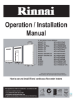
Operation / Installation Manual
Rinnai Demand Duo Systems
IMPORTANT
All Rinnai Demand Duo (DD) systems and components are Watermark Certified by SAI Global as applicable.
The Rinnai DD1 model is certified as a gas storage water heater by the Australian Gas Association (AGA).
AGA CERTIFICATION APPLIES TO DD1 MODELS ONLY. AGA CERTIFICATION DOES NOT
APPLY TO OTHER DD MODELS IN THIS MANUAL.
Important Notice for Installers
Please leave these instructions with the end user after commissioning of the system and alert the end user of the
content in the sections “Warnings” and “Periodic Inspection” and “Maintenance”.
Not suitable as a pool or spa heater.
This appliance shall be installed in accordance with:
WARNING
• Manufacturer’s Installation Instructions
• Current AS/NZS 3000, AS/NZS 3500 & AS/NZS 5601
• Local Regulations and Municipal Building Codes
This appliance must be installed, serviced and removed by an
Authorised Person.
All Rinnai gas products
are A.G.A. certified.
W169
SAI Global
W208
SAI Global
Part No. 15401029 - Version 7
NOTE
TABLE OF CONTENTS
IMPORTANT INFORMATION & WARNINGS ........................................................................ 1
Safety and Regulatory Information .................................................................................................... 1
WARNINGS ............................................................................................................................ 1
Hydrogen Gas ................................................................................................................................... 2
Water Temperature ........................................................................................................................... 2
Gas boosted models only .................................................................................................................. 3
Safety Devices .................................................................................................................................. 3
Water Quality .................................................................................................................................... 3
Regular Care ..................................................................................................................................... 3
Pressure and Temperature Relief (PTR) valve ................................................................................. 3
Expansion Control Valve (ECV) - if fitted .......................................................................................... 4
Servicing and Repair ......................................................................................................................... 4
Insufficient or no hot water ................................................................................................................ 4
Water Heater Valves Discharging Excessively ................................................................................. 4
Expansion Control Valve (ECV) - if fitted .......................................................................................... 5
Service .............................................................................................................................................. 5
GENERAL INSTALLATION INSTRUCTIONS ....................................................................... 6
Regulations ....................................................................................................................................... 6
Appliance Location ............................................................................................................................ 6
HD200e, HD250e, HDC211e (External Models) ............................................................................... 6
HD200i, HDC211i (Internal Models) .................................................................................................. 6
Horizontal Obstructions ..................................................................................................................... 7
Horizontal Flue Terminal Clearances (Extract from AS/NZS 5601) .................................................. 8
Co-Axial Flueing for Internal Models ................................................................................................. 9
Multiple Flue Terminals ................................................................................................................... 10
Common Flue System for Internal models ...................................................................................... 11
Installation ....................................................................................................................................... 11
Assembly ......................................................................................................................................... 12
DD1 Models, Drawing and Specifications ....................................................................................... 13
DD2-DD6 Models Drawing and Specifications ................................................................................ 19
Cold Water Supply .......................................................................................................................... 22
Hot Water Outlet ............................................................................................................................. 22
Return Pump ................................................................................................................................... 22
Gas Supply ...................................................................................................................................... 22
Filling Instructions ........................................................................................................................... 22
Starting Instructions ........................................................................................................................ 22
INSTALLATION HAND OVER MANUAL ............................................................................. 23
Demand Duo Principle of Operation ............................................................................................... 23
Thermostat Operation ..................................................................................................................... 23
Demand Duo Preventative Maintenance ........................................................................................ 23
Tank ................................................................................................................................................ 24
Primary Pump ................................................................................................................................. 24
INFINITY Heat Source .................................................................................................................... 24
INFINITY Fault Codes ..................................................................................................................... 25
Ringmain Pump ............................................................................................................................... 26
Service ............................................................................................................................................ 26
CONTACT INFORMATION .................................................................................................. 29
Rinnai Australia
i
Operation / Installation Manual
IMPORTANT INFORMATION & WARNINGS
Safety and Regulatory Information
The Rinnai Demand Duo systems and components are Watermark Certified by SAI Global as
applicable.
The Rinnai DD1 model is certified as a gas appliance by the Australian Gas Association (AGA).
AGA Certification covers DD1 models only. AGA Certification does not apply to
other DD models covered in this manual.
NOTE
This appliance must be installed correctly by an authorised person and must conform to location
regulations.
The installation must also comply with the instructions supplied by Rinnai. Please keep this instruction
booklet in a safe place for future reference.
This appliance is not intended for use by persons (including children) with reduced physical, sensory
or mental capabilities, or lack of experience and knowledge, unless they have been given supervision
or instruction concerning use of the appliance by a person responsible for their safety.
Any power leads from the water heater system components MUST BE plugged into an external
weatherproof electrical outlet. If the power supply cord of the system is damaged, it MUST BE
replaced by an authorised person in order to avoid a hazard, using genuine replacement parts
available from Rinnai. Take care of not to touch the power plugs with wet hands.
Notice to Victorian Consumers
This appliance must be installed by a person licensed with the Plumbing Industry Commission.
Only a licensed person will have insurance protecting their workmanship.
So make sure you use a licensed person to install this appliance and ask for your Compliance
Certificate.
For Further information contact the Plumbing Industry Commission on 1800 015 129.
WARNINGS
Installation and service only by an authorised person.
•
•
•
•
•
•
DO NOT operate this appliance before reading the manufacture instructions.
DO NOT remove covers while power is on.
DO NOT place articles on or against this appliance.
DO NOT operate with panels, covers or guards removed from this appliance.
DO NOT enclose this appliance.
DO NOT store chemicals or flammable materials near this appliance.
Rinnai Australia
1
Operation / Installation Manual
IMPORTANT INFORMATION & WARNINGS
Hydrogen Gas
If the hot water heater is not used for two weeks or more, a quantity of hydrogen gas, which is highly
flammable, may accumulate in the water heater. To dissipate this safety, it is recommended that a
non-electrically operated hot tap be turned on for several minutes at a sink, or bath, but at dishwasher
or other appliance. During this procedure there must be not smoking, open flame or any electrical
operating nearby. If hydrogen gas is discharged through the tap, it will probably make a sound like air
escaping.
Water Temperature
To meet regulatory requirements the temperature of stored water heater must not be less than 60°C.
The thermostat on your storage tank is factory pre-set to 65°C. The outlet temperature setting of the
INFINITY is factory pre-set to 75°C.
The Thermostat setting must only be adjusted by an Electrician or other suitably
qualified trades person.
NOTE
The access cover to the control system must only be removed by an Electrician
or other suitably qualified trades person.
Scald Hazards
Hot Water can cause scalds.
Children, disabled, and the elderly are at the highest risk of
being scalded.
Feel water temperature before bathing or showering.
Scalds from hot water taps can result in severe injuries to
young children.
Scalds can occur when children are exposed directly to hot
water when they are placed into a bath which is too hot.
• Do stay with children whenever
DO
they are in the bathroom (Take the
phone off the hook).
• Do take them out of the bathroom if
you need to answer the phone or
door.
• Do test the temperature of the
water with your elbow before
placing your child in the bath.
• Do make sure that the tap is turned
off tightly.
• Do install a child proof tap cover
• Consider child-resistant taps or
tap covers, which prevent a small
hand being able to turn on the
tap.
• Consider installing tempering
valves or thermostatic mixing
valves which reduce the hot
water temperature delivered to
taps. Your local plumbing
authority may already require that
these be fitted. Contact your
installer or local plumbing
authority if in doubt.
• DO NOT leave a
DON’T
toddler in the care of
another small child. The
older child may not
have set the water
temperature to a safe
level.
OR
• Do install a child resistant tap.
Rinnai Australia
2
Operation/ Installation Manual
IMPORTANT INFORMATION & WARNINGS
Gas boosted models only
• Do not touch the flue outlet or do not insert any objects
into the flue outlet.
• Keep flammable materials, spray cans, fuel containers,
trees, shrubs and pool chemicals etc. well clear of the
flue outlet.
• Do not use the gas types other than those designated on
HOT!
the data plate. For example, do not use Propane/Butane
gas mixtures on appliances marked Propane Gas.
• Do not use Propane gas on appliances marked as
Natural Gas and vice versa.
Safety Devices
The water heating system is supplied with various safety devices including temperature sensors,
overheat sensors and switches and a Pressure & Temperature Relief (PTR) valve. These devices
must not be tampered with or removed. The water heating system must not be operated unless each
of these devices is fitted and is in good working order.
• DO NOT tamper with or remove safety devices.
WARNING
• DO NOT operate the water heater unless all safety devices are fitted and in
good working order.
• DO NOT block or seal the PTR Valve and drain pipe.
Water Quality
The water quality of most public supplies is suitable for the hot water system. The water quality from
bore wells is generally unsuitable for the hot water system. Refer to the 'Warranty Conditions' for water
quality parameters and how they affect the warranty conditions. If in doubt about the water quality,
have it checked against the parameters listed in the warranty conditions.
If sludge or foreign matter is present in the water supply, a suitable strainer filter should be
incorporated in the water supply to the system.
Regular Care
Over flow tray and drain.
The overflow tray and drain (if fitted) should be periodically checked to ensure there are no blockages.
Pressure and Temperature Relief (PTR) valve
This valve is located near the top of the water heater and is essential for
safe operation. It is normal for the valve to release a small quantity of
water through the drain line during heating.
However, continuous leakage of water from the valve and its drain line
may indicate a problem with the water heater.
L ift lever un til w ater
flo w s fro m d rain lin e
(Lo w er lever g en tly!)
WARNING
Never block the outlet of the PTR valve or it’s drain line for any reason. The easing gear
must be operated at least every 6 months to remove lime deposits and verify that it is
not blocked. Failure to do this may result in the water heater failing.
If the valve does not discharge water when the easing gear lever is opened, or does
not seal again when the easing gear is closed, attendance by an authorised person
must be arranged without delay.
The PTR valve is not serviceable.
Rinnai Australia
3
Operation / Installation Manual
IMPORTANT INFORMATION & WARNINGS
Expansion Control Valve (ECV) - if fitted
Operate the easing lever on the expansion control valve once every six months. It is very important
you raise and lower the lever gently.
Servicing and Repair
Our servicing network personnel are fully trained and equipped to give the best on your Rinnai
appliance. If your appliance needs service, ring one of the service contact numbers on the back of this
booklet.
The pressure and temperature relief valve and expansion control valve must be checked for
performance or replaced by an authorised person at intervals not exceeding 5 years or more
frequently in areas where the water is classified as scaling water (see 'Water Quality').
If the electric conduit, power supply cord or plug to hot water system is damaged, they must be
replaced by an authorised person in order to avoid a hazard. The power supply cord and plug must
be replaced by a genuine replacement part available from Rinnai.
Insufficient or no hot water
Is there electricity supply to the water heater?
• Check to ensure the electric isolating switch(es) at the switchboard (usually marked "Hot
water" or "Water heater") is switched 'ON'.
• Check to ensure that the electric fuses for hot water at the switchboard are intact.
Is there insufficient gas supply for gas booster?
• Check gas is available and turned 'ON'.
• Check the isolation valve in the gas line is opened.
• Refer to your plumber to ensure the gas line has been purged of air after installation.
Are you using more hot water than you think?
• Often end users are surprised at the amount of hot water used, especially when
showering. If the amount of hot water used during the day exceeds the storage capacity of
the hot water system, it is likely that there will be insufficient hot water. Has your plumber
install water saving fixture and/or flow control or pressure limiting valves to reduce
consumption.
Are hot water system valves discharging excessively?
• Refer to the section "hot water system valves discharging excessively".
High gas bills
• If you think your gas bill is too high, investigate the following:
• You may be using more hot water than you think. This applies especially to showering.
Review hot water usage, especially the time taken for showering, and investigate the use
of flow control valves or 'water saving' shower roses. Investigate recent changes to hot
water usage patterns.
• Water heater valves may be discharging excessively. Refer to the section "hot water
system valves discharging excessively".
• There may be hot water leakages in hot water pipes or taps. Have these checked and
rectified by a plumber.
If, after investigating the above, you still require assistance contact Rinnai.
Water Heater Valves Discharging Excessively
Pressure & Temperature Relief (PTR) Valve
It is normal and desirable that this valve allows a small quantity of water to be discharged during the
heating cycle. If it discharges more than a bucket of water during a 24 hour period or discharges
continuously there may be another problem.
If the valve dribbles continuously, try easing the valve gear for a few seconds as described above.
This may dislodge any foreign matter and alleviate the problem.
Rinnai Australia
4
Operation/ Installation Manual
IMPORTANT INFORMATION & WARNINGS
If the valve discharges at high flows, especially at night, it may be as a result of the water pressure
exceeding the design pressure of the water heater. Ask your installer to fit a Pressure Limiting Valve
(PLV).
• NEVER replace the PTR valve with one which has a higher pressure rating than is
specified for your water heater.
WARNING
• If the valve discharges hot water at high flows until the water heater is cold and
then stops discharging until the water reheats there may be a serious problem.
Switch off the power supply in the meter box (the switch marked “WATER
HEATER” or “HOT WATER”) or the insolating switch installed near the water
heater and contact Rinnai.
Expansion Control Valve (ECV) - if fitted
It is normal and desirable that this valve allows a small quantity of water to be discharged during the
heating cycle. If it discharges more than a bucket of water during a 24 hour period or discharges
continuously there may be another problem.
If the valve leaks continuously, try easing the valve gear for a few seconds. This may dislodge any
foreign matter and alleviate the problem. If this does not alleviate the problem contact Rinnai.
Operate the easing gear regularly to remove any lime deposits and to verify that it is not blocked.
Service
The system should be checked and serviced by an authorised person at least every 5 years.
The PTR valve must be replaced at intervals not exceeding five (5) years.
Rinnai has a service and spare parts network with personnel who are trained and equipped to give
the best service on Rinnai appliances.
Rinnai Australia
5
Operation / Installation Manual
GENERAL INSTALLATION INSTRUCTIONS
These instructions apply to the Demand Duo range of Rinnai water heaters:
Models Covered
DD1 200 (external or internal) 250 or 315 (litre tank) N or L (Natural gas or LPG)
DD1 250 (external) 250 or 315 (litre tank) N or L (Natural gas or LPG)
DD1C 211 (external or internal) 250 or 315 (litre tank) N or L (Natural gas or LPG)
DD2 200 (external or internal) 250 or 315 (litre tank) N or L (Natural gas or LPG)
DD2C 211 (external or internal) 250 or 315 (litre tank) N or L (Natural gas or LPG)
DD3 200 (external or internal) 250 or 315 (litre tank) N or L (Natural gas or LPG)
DD3C 211 (external or internal) 250 or 315 (litre tank) N or L (Natural gas or LPG)
DD4 200 (external or internal) 250 or 315 (litre tank) N or L (Natural gas or LPG)
DD4C 211 (external or internal) 250 or 315 (litre tank) N or L (Natural gas or LPG)
DD5 200 (external or internal) 250 or 315 (litre tank) N or L (Natural gas or LPG)
DD5C 211 (external or internal) 250 or 315 (litre tank) N or L (Natural gas or LPG)
DD6 200 (external or internal) 250 or 315 (litre tank) N or L (Natural gas or LPG)
DD6C 211 (external or internal) 250 or 315 (litre tank) N or L (Natural gas or LPG)
Regulations
For continued safety of this appliance it must be installed, operated and maintained by authorised
person in accordance with manufacture's instructions, current with AS/NZS 3500 and AS/NZS 5601,
local regulations and municipal building codes.
Rinnai Demand Duo hot water systems are not suitable or approved as pool heater.
Read these instructions carefully before proceeding with the installation.
Appliance Location
Ensure reasonable access for installation, servicing and removal. All valves, controls and pumps etc
must be easily accessible.
Rinnai Demand Duo tanks and any free standing frames must be mounted on a solid level base,
capable of supporting the weight of the appliance when full of water. Ensure components are not
allowed to stand in water. Spacers under the tank are recommended in wet areas.
All Demand Duo tanks are "left handed" with the water connections to the left when viewing the
thermostat housing from the front.
These systems are combined with Rinnai INFINITY HD series, HD200e (VRM-2632WC), HD200i
(VRM-2632FFUC), HD250e (VRM-3237WC), HDC211e (KM3237WDC) and HDC211i
(KM3237FFUDC).
Rinnai INFINITY and HD units are fan assisted appliances and thus have lower clearances than a
natural draft appliance of the same MJ rating.
HD200e, HD250e, HDC211e (External Models)
This appliance is designed for ‘Outdoor’ Installation only. As such, it must be located in an above
ground open air situation with natural ventilation, without stagnant areas, where gas leakage and
products of combustion are rapidly dispersed by wind and natural convection.
This appliance must be mounted on a vertical structure with the water and gas connections on the
underside pointing downwards. For appliances installed on elevated structures or under floors specific
requirements apply. Refer to AS/NZS 5601 Section 6 for details.
This appliance must not be used as a domestic spa or swimming pool heater.
Location of the appliance flue terminal must be in accordance with Section 6 and Figure 6.2 of
AS/NZS 5601. Figure 6.2 is reproduced in the ‘Horizontal Flue Terminal Clearances’ section of these
instructions. Note: that AS/NZS 5601 is current at the time of printing. It is the installers’
responsibility to ensure current requirements are met.
HD200i, HDC211i (Internal Models)
This appliance is designed for ‘Indoor’ installation only. It may be installed ‘Outdoors’ in an enclosure
if the requirements of AS/NZS 5601 Section 6 are satisfied. An enclosure is defined as a
compartment, enclosed are of partitioned off space primarily used for the installing of the appliance.
Rinnai Australia
6
Operation / Installation Manual
GENERAL INSTALLATION INSTRUCTIONS
If installed in an enclosure either Internally or Externally, the location should be ventilated to allow gas
to dissipate and provision must be made for the safe disposal of any leaking water to a visible location.
This appliance must not be used as a domestic spa or swimming pool heater.
Two types of flue systems are available:
1. The Rinnai Commercial Common Flue System. This system is certified and suitable for use with
Rinnai non-condensing internal commercial continuous flow water heaters.
2. The Rinnai Co-Axial FFU flue system. This system is certified and suitable for use with Rinnai
condensing and non-condensing internal commercial continuous flow water heaters.
Non-Condensing models are:
REU-V2632FFUC, REU-VM2632FFUC and REU-VRM2632FFUC.
Condensing models are:
REU-KM2635FFUD, REU-KM2635FFUDC, REU-KM3237FFUD and REU-KM3237FFUDC.
The use of non Rinnai flue components may result in a dangerous situation and violates regulations.
The appliance(s) must be located so that the flue terminal exits the building at a suitable point.
For detailed information refer to “FLUEING FOR INTERNAL MODELS” on page 9.
This appliance must be located so that the flue terminal exits the building at a suitable point.
If a horizontal (wall) terminal FFWALLTERM is used, the location must be in accordance with
Section 6 and Figure 6.2 of AS/NZS 5601. Figure 6.2 is reproduced under ‘HORIZONTAL FLUE
TERMINAL CLEARANCES’ on page 8 of this manual.
If a vertical (roof) terminal FFROOFCOWL is used, the location must be in accordance with
Section 6 of AS/NZS 5601 and the ‘FLUEING FOR INTERNAL MODELS’ on page 9.
Horizontal Obstructions
AS/NZS 5601-2010 ‘Gas Installations’ stipulates
a minimum horizontal clearance of 500 mm
between a building structure and obstruction
facing the terminal. For Rinnai External
continuous flow water heaters such a building
structure must ‘obstruct’ the full front cover height
of the appliance, or extend vertically above and
below the front cover. There must be no partial
obstructions to the front cover of the appliance or
any other parts of the appliance casing. This will
avoid the appliance failing to operate under windy
conditions.
Rinnai Australia
500mm
7
Operation / Installation Manual
GENERAL INSTALLATION INSTRUCTIONS
Horizontal Flue Terminal Clearances (Extract from AS/NZS 5601)
Flue terminal
Fan assisted flue appliance only
Ref.
Gas meter
Electricity meter or fuse box
Mechanical air inlet
Min. clearances (mm)
Natural draft Fan assisted
Item
Below eaves, balconies and other projections:
• Appliances up to 50 MJ/h input
300
• Appliances over 50 MJ/h input
500
300
b
From the ground, above a balcony or other surface *
300
300
c
500
300
d
Front a return wall or external corner *
From a gas meter (M) (see 5.11.5.9 for vent terminal location of regulator )
(see Table 6.6 for New Zealand requirements)
1000
1000
e
From an electricity meter or fuse box (P) †
500
500
f
From a drain pipe or soil pipe
150
75
g
Horizontally from any building structure* = or obstruction facing a terminal
500
500
h
From any other flue terminal , cowl, or combustion air intake †
500
300
Horizontally from an openable window, door, non-mechanical air inlet, or any other opening into a building
with the exception of sub-floor ventilation:
a
j
• Appliances up to 150 MJ/h input *
500
300
• Appliances over 150 MJ/h input up to 200 MJ/h input *
1500
300
• Appliances over 200 MJ/h input up to 250 MJ/h input *
1500
500
• Appliances over 250 MJ/h input *
1500
1500
-
1500
• All fan-assisted flue appliances , in the direction of discharge
k
n
200
From a mechanical air inlet, including a spa blower
1500
1000
Vertically below an openable window, non-mechanical air inlet, or any other opening into a building with the
exception of sub-floor ventilation:
• Space heaters up to 50 MJ/hr input
150
• Other appliances up to 50 MJ/hr input
500
500
• Appliances over 50 MJ/h input and up to 150 MJ/h input
1000
1000
1500
1500
• Appliances over 150 MJ/h input
* - unless appliance is certified for closer installation
† - Prohibited area below electricity meter or fuse box extends to ground level.
150
NOTES:
1 Where dimensions c, j or k cannot be achieved an equivalent horizontal distance
measured diagonally from the nearest discharge point of the terminal to the opening
may be deemed by the Technical Regulator to comply.
2
3
See Clause 6.9.4 for restrictions on a flue terminal under a covered area.
See Figure J3 for clearances required from a flue terminal to an LP Gas cylinder.
A flue terminal is considered to be a source of ignition.
4
For appliance s not addressed above acceptance should be obtained from the Technical Regulator.
FIGURE 6.2 (in-part) MINIMUM CLEARANCES REQUIRED FOR BALANCED FLUE TERMINALS, FAN-ASSISTED FLUE
TERMINALS, ROOM-SEALED APPLIANCE TERMINALS AND OPENINGS OF OUTDOOR APPLIANCES
Rinnai Australia
8
Operation / Installation Manual
GENERAL INSTALLATION INSTRUCTIONS
Co-Axial Flueing for Internal Models
This system is certified and suitable for use with Rinnai non-condensing internal commercial
continuous flow water heaters.
The Rinnai INFINITY Flueing system must be installed in accordance with the instructions supplied
with the flue terminal. Non Rinnai flueing systems MUST NOT be used.
Installations can consist of both horizontal and vertical runs to a maximum of 9 metres with a
maximum of three 90° bends.
The Rinnai internal flueing system is highly
versatile and makes installation of an internal
water heater simple and convenient.
The flueing for internal water heaters is a
Co-Axial design. It is manufactured from an
aluminium alloy inner flue pipe to discharge
product of combustion and a thermoplastic
outer pipe for air supply to the appliance. The
water heater is a room sealed appliance.
NOTE: Each Rinnai water heater is
flued individually.
As it is fan assisted, the water heater can be
flued
vertically,
horizontally
or
any
combination of both, to a maximum of 9
metres and 3 x 90 degree bends.
DD1 & Manifold Pack 3 with Horizontal Flueing
Horizontal flueing can be used as a direct wall
flue or extended from another internal wall.
Vertical flueing is used when the water heater
needs to be flued vertically through the roof.
A condensate trap is required when vertical
flue exceeds 1.5 metres.
Rinnai HD internal water heaters are
classified as ‘room sealed’ appliances. Flue
systems must be installed in accordance with
Rinnai Installation Instructions (supplied with
flue terminals), local gas fitting regulations,
municipal building codes, AS/NZS 5601 and
all other relevant statutory regulations.
The flue terminal clearances in AS/NZS 5601
do not apply to the HD200e, HD250e or
HDC211e heaters installed side by side.
These appliance are AGA certified to be
located side by side, for both internal an
external models.
DD6 Internal Flued System
CO-AXIAL INTERNAL FLUEING ORDER CODES
a. Elbow 90° Bend & Adaptor FFBEND90BA
b. Ceiling / Wall Ring
FFWSEAL
c. External Wall Plate
FFWPLATE
d. Horizontal Flue Terminal
FFWALLTERM
e. Universal Bend (2 x 45°)
FFBEND
f.
Flue Pipe 1000 mm length* FFPIPE1000
g. Vertical Flue Terminal*
FFROOFCOWL
h. Condensate Trap
FFCONDK
i.
Vertical Adaptor
FFADPT
* Supplied with pipe clip
Discuss with your Rinnai Commercial representative
for further details.
DD6 Direct Wall Flue
Rinnai Australia
9
Operation / Installation Manual
GENERAL INSTALLATION INSTRUCTIONS
Only Rinnai Flueing systems can be used with Internal Water Heaters. Non-Rinnai
Flueing systems are not certified and will not be covered under warranty.
NOTE
If flue length exceeds 1.5 metres, dip-switch 1 of SW1 located inside the HD unit is to be switched to
the ‘OFF’ position.
For all further information on Internal Flueing, please refer to separate Flueing manual supplied with
Flueing components.
Multiple Flue Terminals
Dimension 'H' in AS/NZS 5601 Figure 6.2 does not apply when multiple Rinnai external water heaters
of the same model are installed on the same vertical face with flue terminals at the same height. Under
these conditions appliances can abut each other as shown below:
The terminal clearances stated in AS/NZS 5601 do not apply to the INFINITY HD200 and 26 litre
internal water heaters when they are installed side by side. AGA certification allows for a minimum
horizontal separation of 160 mm for roof terminals and 270 mm for wall terminals.
FFWALLTERM
270
FFWPLATE
350
225
Minimum clearance 500
160
FFROOFCOWL
FFPIPE1000
FFCPIPE
UP
Rinnai Australia
UP
10
UP
Operation / Installation Manual
GENERAL INSTALLATION INSTRUCTIONS
All Rinnai Demand Duo systems with HD200 water heaters have the manifold and
flue centres at 375 mm. This is slightly further apart than above and is acceptable.
NOTE
Common Flue System for Internal models
The Rinnai Commercial Common Flue System is certified and suitable only for use with Rinnai noncondensing internal commercial continuous flow water heaters. It is NOT suitable for use with Rinnai
condensing water heaters. Refer suitable model listing below:
Suitable only for use with the following non-condensing models:
REU-V2632FFUC, REU-VM2632FFUC and REU-VRM2632FFUC.
NOT suitable for use with condensing models:
REU-KM2635FFUD, REU-KM2635FFUDC, REU-KM3237FFUD and REU-KM3237FFUDC.
A Common Flue System can be used. This system utilises adaptors to connect multiple Internal Water
Heaters to a Natural Draft Flue. (see the instruction manual supplied with the Rinnai Common Flue
for details).
Installation
Unpacking DD1
Remove outer cardboard box. Remove screws attaching feet on tank to wooden pallet. Carefully
remove system from pallet and inspect for any transport damage. Ensure that PTR valve and brass
plug 32 mm supplied in box is located and stored. DO NOT install if any components are damaged.
Unpacking DD2 - DD6
Tank:
Remove outer cardboard box. Remove screws attaching feet on tank to wooden pallet.
Carefully remove tank from pallet and inspect for any transport damage. Ensure that PTR valve,
supplied in box is located and stored. DO NOT install if any components are damaged.
HD water heaters:
With cardboard box in upright position, remove packing straps and slide lid upwards. Remove water
heater from base when required for installation.
Manifold:
Remove manifold, pump and PTR valve(s) and fittings as per bill of materials table below:
Rinnai Australia
11
Operation / Installation Manual
GENERAL INSTALLATION INSTRUCTIONS
DD1 200
External/Internal
DD1C 211
External/Internal
DD1 250
External
DD2 200
External/Internal
DD2C 211
External/Internal
DD3 200
External/Internal
DD3C 211
External/Internal
DD4 200
External/Internal
DD4C 211
External/Internal
DD5 200
External/Internal
DD5C 211
External/Internal
DD6 200
External/Internal
DD6C 211
External/Internal
N/A
BOILER VALVE
packed with
manifold
N/A
FITTINGS
packed with
manifold
N/A
1 * HT 575
N/A
N/A
N/A
2 * HT 575
N/A
N/A
N/A
1 * HT 575
1 * HT 575
N/A
N/A
1 * HT 575
1 * HT 575
N/A
N/A
1 * HT 575
2 * HT 575
N/A
32mm Tee
1 * HT 575
2 * HT 575
N/A
32mm Tee
1 * HT 575
N/A
1 * Valve
N/A
1 * HT 575
N/A
1 * Valve
N/A
1 * HT 575
N/A
1 * Valve
N/A
1 * HT 575
N/A
1 * Valve
N/A
1 * HT 575
N/A
1 * Valve
N/A
1 * HT 575
N/A
1 * Valve
N/A
PTR VALVE
packed with Tank
PTR VALVE
packed with manifold
1 * HT 575
* ALL HT 575 PTR valves are rated at 850 kPa
Assembly
Demand Duo 1
•
•
Position tank in desired position.
Attach PTR valve supplied in box to 20mm port at top of tank. As for the DD1 200e / 200i 250L or
315L, plug off second port with 20mm plug supplied. For DD1 250e/211e/211i 250L or 315L,
attach another PTR valve to second port at the top of tank.
• Plug off second cold inlet port at the bottom of the tank with 32 mm plug supplied with tank.
• Run PTR valve drains to suitable discharge position.
Demand Duo 2 - Demand Duo 6
•
•
•
•
•
•
•
•
•
•
Position tank in desired position.
Attach PTR valve supplied in tank box to 20mm port at top of tank.
Attach second valve to the other 20 mm port at top of tank.
Attach the third PTR valve on a DD3 to the hot outlet with the 32 mm threaded tee, nipple and 32
mm male/20mm female reducer supplied.
Run PTR valve drains to suitable discharge position.
Mark line on wall where top of HD water heaters are to be located.
- A useful nominal height is 1500mm from floor level. This may change depending on desired
position of flue terminal. It may be higher in trafficable areas or to reduce vertical flue length, for
example.
For HD200 heaters on DD2,3, 4, 5 and 6, mark 375 mm centres, allowing sufficient space
between tank and the nearest heater for the primary pump(s) and pipework. For HD250e/
HDC211e/HDC211i on DD2 - DD6 mark 500mm centres.
Attach first heater to wall, preferably a centre heater.
Connect manifold to heater and confirm that marked centres match the manifold.
Attach rest of heaters to wall and connect manifold.Attach 32mm tee to cold inlet on tank, with
union as required. Cold inlet is lowest fitting on the tank, 285 mm from the tank base.
Rinnai Australia
12
Operation / Installation Manual
GENERAL INSTALLATION INSTRUCTIONS
•
•
•
Join inlet of primary pump to tee at cold inlet fitting on tank with 32mm pipe.
Join outlet of primary pump to inlet of cold (bottom) pipe on manifold.
Fit cover so that pump is weatherproof. Ensure power cable enters pump from below and that it
is not a track for water to enter pump.
NOTE
•
•
•
Remaining port on the tee is the cold water inlet to the system. It is also the ringmain return
point.
Extend 32 mm hot return pipe (centre pipe) from end of manifold to the return fitting on the tank
with union as required. This fitting is 385 mm from the tank base.
System is now ready to be plumbed to the building.
NOTE
•
•
•
When direct flueing through the wall that the water heaters are mounted on, it
may be necessary to attach flue to water heater and push it through the wall
before attaching the water heater to the wall.
Primary pump and/or primary pipe work may need to be increased for long runs of
primary pipe work, or installation with many bends in the pipe work between tank
and manifold.
Plug primary pump(s) into the thermostatic controller mounted on the tank.
Plug power supply to the thermostatic controller into an available GPO. DO NOT turn ‘ON’.
Plug water heaters on DD2 - DD6 to an available GPO (one per heater is required). DO NOT
turn ‘ON’.
DD1 Models, Drawing and Specifications
DD Model
*DD1 200e/
250 ext
DD1C 211e
250 ext
DD1 200e/
315 ext
*DD1 200i/
250 int
DD1C 211e
315 ext
DD1 200i/
315 int
DD1C 211i
250 int
*DD1 250e/
250 ext
DD1C 211i/
250 int
DD1 250e/
315 ext
*DD 250
DD 315
DD COMBO
250
DD COMBO
315
PTR
Inclusions
Primary
pump
1 * HT 575
(46 kW)
1 * HT 575
(46 kW)
1 * HT 575
(46 kW)
1 * HT 575
(46 kW)
1 * HT 575
(46 kW)
1 * HT 575
(46 kW)
1 * HT 575
(46 kW)
2 * HT 575
(92 kW)
1 * HT 575
(46 kW)
2 * HT 575
(92 kW)
1 * HT 575
(46 kW)
1 * HT 575
(46 kW)
1 * HT 575
(46 kW)
1 * HT 575
(46 kW)
UPS20 60B
UPS25 80B
UPS20 60B
UPS20 60B
UPS25 80B
UPS20 60B
UPS25 80B
UPS20 60B
UPS25 80B
UPS20 60B
N/A
N/A
N/A
N/A
All Dimensions are (mm)
MJ Rating
Total
(HD Water System
Hot
Heater)
Weight
(kG)
RP1 1/4”
199
110
(32mm)
RP1 1/4”
211
125
(32mm)
199
RP1 1/4”
120
(32mm)
199
RP1 1/4”
110
(32mm)
RP1 1/4”
211
125
(32mm)
199
RP1 1/4”
120
(32mm)
RP1 1/4”
211
125
(32mm)
RP1 1/4”
250
120
(32mm)
RP1 1/4”
211
125
(32mm)
RP1 1/4”
250
130
(32mm)
RP1 1/4”
N/A
73
(32mm)
N/A
RP1 1/4”
88
(32mm)
N/A
RP1 1/4”
75
(32mm)
N/A
RP1 1/4”
90
(32mm)
Fittings
Cold
PTR
*RP1 1/4”
(32mm)
*RP1 1/4”
(32mm)
RP1 1/4”
(32mm)
*RP1 1/4”
(32mm)
*RP1 1/4”
(32mm)
RP1 1/4”
(32mm)
*RP1 1/4”
(32mm)
*RP1 1/4”
(32mm)
*RP1 1/4”
(32mm)
RP1 1/4”
(32mm)
*RP1 1/4”
(32mm)
RP1 1/4”
(32mm)
RP1 1/4”
(32mm)
RP1 1/4”
(32mm)
RP 3/4”
(20mm)
RP 3/4”
(20mm)
RP 3/4”
(20mm)
RP 3/4”
(20mm)
RP 3/4”
(20mm)
RP 3/4”
(20mm)
RP 3/4”
(20mm)
RP 3/4”
(20mm)
RP 3/4”
(20mm)
RP 3/4”
(20mm)
RP 3/4”
(20mm)
RP 3/4”
(20mm)
RP 3/4”
(20mm)
RP 3/4”
(20mm)
Gas
RP 3/4”
(20mm)
RP 3/4”
(20mm)
RP 3/4”
(20mm)
RP 3/4”
(20mm)
RP 3/4”
(20mm)
RP 3/4”
(20mm)
RP 3/4”
(20mm)
RP 3/4”
(20mm)
RP 3/4”
(20mm)
RP 3/4”
(20mm)
RP 3/4”
(20mm)
RP 3/4”
(20mm)
RP 3/4”
(20mm)
RP 3/4”
(20mm)
DD1 250L only tank supplied with 32 mm brass plug to plug one of the unused cold
inlet ports.
NOTE
Rinnai Australia
13
Operation / Installation Manual
GENERAL INSTALLATION INSTRUCTIONS
DD1 200e / 250L & 315L
SECOND COLD INLET OR
250L: 700
315L: 385
850 kPa PTR
845
INCLUDED
NOTE: PLUG UNUSED COLD INLET PORT WITH BRASS PLUG 32 MM SUPPLIED WITH TANK
Rinnai Australia
14
Operation / Installation Manual
GENERAL INSTALLATION INSTRUCTIONS
845
SECOND COLD INLET OR
250L: 700
315L: 385
DD1 200i / 250L & 315L
NOTE: PLUG UNUSED COLD INLET PORT WITH BRASS PLUG 32 MM SUPPLIED WITH TANK
Rinnai Australia
15
Operation / Installation Manual
GENERAL INSTALLATION INSTRUCTIONS
DD1 250e / 250L & 315L
SECOND COLD INLET OR
250L: 700
315L: 385
x2
NOTE: PLUG UNUSED COLD INLET PORT WITH BRASS PLUG 32 MM SUPPLIED WITH TANK
Rinnai Australia
16
Operation / Installation Manual
GENERAL INSTALLATION INSTRUCTIONS
DD 250L & 315L
COLD IN
ALTERNATE RETURN
250L: 700
315L: 385
x2
NOTE: PLUG UNUSED COLD INLET PORT WITH BRASS PLUG 32 MM SUPPLIED WITH TANK
Rinnai Australia
17
Operation / Installation Manual
GENERAL INSTALLATION INSTRUCTIONS
DD COMBO 250L & 315L
COLD IN
ALTERNATE RETURN
250L: 700
315L: 385
x2
NOTE: PLUG UNUSED COLD INLET PORT WITH BRASS PLUG 32 MM SUPPLIED WITH TANK
Rinnai Australia
18
Operation / Installation Manual
GENERAL INSTALLATION INSTRUCTIONS
DD2-DD6 Models Drawing and Specifications
All dimensions are (mm)
DD Model
A
B
C
D
E
DD2 200
Ext/Int.
DD3 200
Ext/Int.
375
725
1825
715
600
375
1100
2200
715
600
DD4 200
Ext/Int.
DD5 200
Ext/Int.
DD6 200
Ext/Int.
375
1475
2575
715
600
375
1850
2950
715
600
375
2225
3325
715
600
Tank Model
250 Litre
315 Litre
HD Model
HD200e
HD200i
F
G
285
385
J
410
340
K
510
440
PTR
Inclusions
Primary
pump
MJ Rating
Gas Boost
(HD200’s)
2 * HT575
UPS25(92 kW)
80B
3 * HT575
UPS25(138 kW) +
80B
Tee
1 * HT575
UPS25+ 1*
80B
Boiler
2 *UPS25Valve
80B
(362 kW) 2 *UPS2580B
H
1475
1855
I
1690
2080
L
610
540
M
Dry Weight
60 kg
72 kg
398
Total
System
Weight
(315L)
115
597
135
796
155
995
175
1194
190
Wet Weight
310 kg
385 kg
1500
65°C
E
A
B
D
C
JKL M
Rinnai Australia
I HG F
19
Operation / Installation Manual
GENERAL INSTALLATION INSTRUCTIONS
Typical Rinnai Demand Duo DD2 system installation
19801023
MP2
32201719
32201719
19801023
17201046
19001021
17201042
16601080
DDUPS2580N
19801022
16601080
19801022
19801023
19801023
Pipe & fittings
by installer
16601080
32201722
32201722
16001045
16001045
32201719
Pipe & fittings
by installer
Pipe & fittings
by installer
16001045
Combo Tank
DD2 KIT Exploded Assembly Diagram
Pump Set
Components
Pipe & fittings
by installer
Typical Rinnai Demand Duo DD3 system installation
19801023
32201719
17201046
32201719
32201719
19801023
19001021
19001021
17201046
17201042
16601080
19801006
DDUPS2580N
19801022
16601080
19801022
19801023
19801023
16601080
32201722
32201722
16001045
16001045
Pipe & fittings
by installer
19801023
MP3
Pipe & fittings
by installer
16001045
Combo Tank
DD3 KIT Exploded Assembly Diagram
Pump Set
Components
Pipe & fittings
by installer
Rinnai Australia
20
Operation / Installation Manual
GENERAL INSTALLATION INSTRUCTIONS
Typical Rinnai Demand Duo DD4 system installation
32201719
32201719
17201046
19001021
17201042
16601080
DDUPS2580N
19801022
16601080
19801022
16601080
19801023
Pipe & fittings
by installer
19801023
32201722
19801023
32201722
32201722
32201722
16001045
16001045
32201719
Pipe & fittings
by installer
Pipe & fittings
by installer
16001045
Combo Tank
19801023
MP 2
MP 2
DD4 KIT Exploded Assembly Diagram
Pump Set
Components
Pipe & fittings
by installer
Typical Rinnai Demand Duo DD5 & DD6 system installation
19801023
32201719
17201046
32201719
Pipe & fittings
by installer
32201722
19801023
19801023
32201722
32201722
16001045
32201719
Pipe & fittings
by installer
Pipe & fittings
by installer
16001045
Combo Tank
19801023
MP 3
MP 2 or 3
DD5/6 KIT Exploded Assembly Diagram
19001021
30001718
19801022
19801022
19801023
32201722
32201722
16001045
Dual Pump Assembly
Pipe & fittings
by installer
Rinnai Australia
21
Operation / Installation Manual
GENERAL INSTALLATION INSTRUCTIONS
Cold Water Supply
•
•
•
Connect cold water pipe work to one of the cold inlets of tank, including required valves as
shown in diagrams on previous page to comply to AS/NZS 3500 and local regulations. (Block
unused cold port with brass plug 32 mm).
Maximum cold water inlet pressure is 650 kPa. Fit pressure limiting valve (rated @ 700 kPa) if
cold water inlet pressure is in excess of 650 kPa.
For ease of draining, it is advisable to fit a "Tee" piece with a capped valve between the cold
water isolation valve and the cold water inlet connection on the Demand Duo storage Tank. Tap
provided.
Hot Water Outlet
•
•
Connect hot water outlet pipe to 32mm fitting on upper left hand side of the storage Tank with
union and isolation valve as required.
Ensure adequate insulation / lagging is fitted to hot water pipe to minimize heat loss.
Return Pump
•
•
A secondary or building return pump may be installed in conjunction with the Rinnai Demand
Duo hot water system. Pump should be sized for minimal temperature loss around the ringmain.
Pump must have a check valve on the discharge.
Return line from building loop is connected to the cold water supply pipe after the check valve.
From that point onwards the cold pipe should be insulated.
Gas Supply
•
•
•
•
•
•
•
•
Check gas type of Rinnai INFINITY matches gas supply available (LPG or Natural) on job site.
Gas inlet connection is located at the front bottom of the weather shroud on a DD1 and is the top
pipe on a DD2 - DD6 manifold.
Appropriate gas isolation valve to be fitted to DD1, DD2 - DD6 have gas isolation valves per
water heater.
Ensure gas pipe sizing is adequate to deliver the required volume / pressure. Pipe size used on
inlet fitting is no indication of pipe size required.
Refer to appropriate pipe sizing chart in Appendix "F" AS/NZS 5601 for appropriate sized gas
pipe that should be used to ensure adequate gas supply.
Gas meter / LPG cylinder & regulator should also be of a suitable size to ensure sufficient gas
supply to the gas installation.
Purge gas pipe to ensure removal of debris etc prior to final connection.
Check for gas escapes using suitable methods as listed in Appendix "E" AS/NZS 5601.
Filling Instructions
Do not turn on pump / gas booster before cylinder and water heater are completely full of
water.
• Flush cold water inlet pipe to remove any debris before final connection to cold water inlet on
Rinnai Demand Duo cylinder.
• Turn on hot water tap to allow air to be expelled while cylinder is filling with cold water.
• Slowly open cold water isolation valve on cold water supply pipe.
• Allow cylinder to fill. Turn off hot water tap once non-aerated water flows through hot water tap.
• Check all connections for water leakage. Tighten as required.
• Purge gas lines until gas is available at water heaters.
• Prime circulating pump(s) before start up by removing chrome screw and allowing water to drip
out the end of the pump shaft.
Starting Instructions
•
•
•
•
Turn all GPO's ON.
Thermostat will initiate.
For standard systems "75" should appear in the maintenance monitor window on the gas heater.
When flow is created by primary pump. That is the outlet temperature from the water heater. It
must be higher then the thermostat set point.
Thermostat will display temperature of water in tank. When it reaches the 65°C set point the
pump and therefore, water heater will stop. The display on the water heater will not be lit when
not operating.
Rinnai Australia
22
Operation / Installation Manual
INSTALLATION HAND OVER MANUAL
Demand Duo Principle of Operation
Cold water enters the storage tank after passing through an isolation and non return valve.
A tee is fitted to the cold inlet pipe down stream from the non return valve. From this tee, one branch
connects to the lower inlet of the storage tank and the other branch connects to the primary (tank
circulation) pump. (Not applicable to DD1 Models). This pumps water to the inlet of the INFINITY(S)
heat source. The INFINITY will only operate when this pump is running.
The heated water from the INFINITY returns to the tank at the second lowest connection point, located
above the cold inlet.
Hot water leaves the tank from the top of the tank. This may be circulated around the building and
returned, via a ringmain pump (set) to the cold inlet before the tee as described above.
When there is a hot water draw off, cold water enters the tank and pushes the hot water out of the
tank towards the outlet, as per any storage hot water system.
When the temperature in the tank drops below the thermostat set point, the thermostat activates the
primary pump(s). They draw water from the cold water feed to the tank, the tank itself, or a
combination of both. As stated previously, this water is then heated by the INFINITY and returns to
the tank heated. This process is continued until the thermostat set point is reached and the pump is
switched off.
The outlet temperature setting of the INFINITY must be set at least three (3) degrees hotter then the
thermostat set point. Factory settings are: INFINITY 75°C, Thermostat 65°C.
Thermostat Operation
•
•
•
•
•
•
•
•
•
•
•
•
•
•
•
Thermostat to control the operation of primary pumps between storage tank and external heat
source, such as HD200, HD250, HDC211.
Circuit board is housed in a plastic box with a see through front cover. Power lead with plug, two
sockets and a temperature probe on lead leave the base of the box.
Can be set up as a DD1, where one power outlet is activated if the tank temperature drops below
set point and the other is permanently active for the HD200, HD250 or HDC211 to plug into or as
a DDCOMBO where one or both power outlets are activated if the tank temperature drops below
set point.
Circuit board includes a display that shows measured water temperature.
“tt” indicates tank temperature when set point is reached.
“P” indicates that temperature has fallen below set point (less differential) and power to primary
pump(s) is activated.
Circuit board mounted LED is lit when power outlet is active when configured to provide power to
a pump. When set as power supply to HD, as a DD1, LED is not lit when power outlet is active.
Pump load per power outlet is maximum 1000 watts. Total power supply to run both pumps
simultaneously is 7.5 Amps. Confirm with pump details.
Available temperature set points are 65°C, 70°C, 75°C, and 80°C.
Available temperature differentials are -3°C and -5°C.
Example: if temperature set point is 65°C and differential is -3°C pump will be switched on when
temperature is below 62°C and is switched off when temperature reaches 65°C
Start up sequence for above example will initiate then show: Low: 62, High: 65.
This sends power to the tank mounted GPO (or direct to the primary pump on a DD1). This will
start the operation of the primary pump(s).
Ensure thermostat sensor is pushed all the way into the well in the tank.
Check that power is available at pump or GPO if necessary.
Demand Duo Preventative Maintenance
All Items
•
Inspect for damage, corrosion or water leaks.
Rinnai Australia
23
Operation / Installation Manual
INSTALLATION HAND OVER MANUAL
Tank
•
•
•
•
Ensure that tank is not leaking.
Ensure that PTR valves are not leaking. It is normal for PTR valve to operate during the heating
cycle, relieving pressure as the water is expanding. The PTR Valve is rated to 850 kPa and cold
inlet pressure should not exceed 500-700 kPa. If it does, then a pressure reduction valve should
be fitted to the cold water inlet.
Valve may be operating if water temperature in tank is close to 99°C. If this is the case the
thermostat or other heating equipment has failed to operate correctly. Contact Rinnai service
department.
If pressure and temperature are low but valve is leaking, pull the lever for up to 30 seconds, as
some foreign material may be jammed in the valve seat. If valve fails to seat correctly, valve
should be replaced. PTR Valves are a non-repairable safety device and should be replaced with
the correct model and pressure rating.
Primary Pump
•
•
•
•
•
•
•
•
•
•
•
•
•
•
•
•
DD1 = Grundfos UPS20-60B set to speed 3
DD1C = Grundfos UPS25-80B set to speed 3
DD2,3,4 = Grundfos UP 25-80B
DD2,3,4C = Grundfos UP32-100
DD5,6 = 2 x Grundfos UP25-80B
DD5, 6C = 2 x Grundfos UP32-100
DD1 wired directly to thermostat, DD2,3,4 plugs into switched GPO on tank, DD5,6 two pumps
plugged into double switched GPO in tank.
Some projects may have larger and/or dual pumps for redundancy or long primary pipe run
situations.
Pump(s) operate when activated by thermostat, as indicated by green light on thermostat.
Ensure that pumps are installed in a weather proof location or protected from being subjected to
water ingress. By themselves they are not. Wet pump electric’s may cause failure. Water can run
along power lead so keep the lead looping under the pump and curving upwards toward the
electrical box.
Ensure shaft is horizontal. DO NOT aim shaft upwards or downwards.
DO NOT locate terminal box under pump housing. Position it on top preferable or on side
Bleed pump with chrome screw at end of pump casing. This will be facing towards you when
the pump shaft is horizontal. Pump runs on water bearing and is critical for life of pump.
Excessive noise indicates damage or lack of bleed.
When this screw is removed the spinning / stationary impeller shaft can be inspected.
Ensure pump direction of flow arrow is towards INFINITY(S).
If shaft is spinning but there is no flow: Check ball valves and any non return valve for correct
installation and operation. UP25-80B and UP32-100 pumps have inbuilt ball valves in the
unions. Line up screwdriver slot parallel to pipe to position them open.
INFINITY Heat Source
•
•
•
Ensure that filter at water inlet is clean. NOTE: that this is an ‘O’ ring seal and does not need
to be excessively tightened. Just make sure ‘O’ ring is engaged inside machined surface
in brass housing. Isolate water supply to DD before removing filter for cleaning and
inspection. Ensure water in storage cylinder is not excessively hot before removing
INFINITY inlet filter.
Ensure all INFINITY's are operating. Ensure power is available to INFINITY if it is not operating.
Can check GPO. DD1 is hard wired to junction box. DD2 - DD6: ensure power is available to the
INFINITY before applying power to thermostat and pump(s).
Many new jobs or ones where the gas supply has been modified need to purge the gas supply
lines as they are full of air. Purge should be carried in accordance with AS/NZS 5601, Appendix
'D'.
Rinnai Australia
24
Operation / Installation Manual
INSTALLATION HAND OVER MANUAL
•
•
•
•
•
All models up to late 2006: Look at flame through inspection window for conical shape, blue
base and yellow tip. Flame height will vary if heater is modulating. Inspection window is located
in front cover of appliance.
All new HD models: when operating the number displayed should be higher than the
temperature setting on the tank mounted thermostat.
• Eg Tank = 65°C, INFINITY = 75°C. These are factory standard settings.
• Eg Tank = 80°C, INFINITY = 85°C. These are the maximum allowable settings.
All new HD models will display a fault number if one has occurred. Below is a full list of fault
codes.
In jobs that operate for long hours and/or in dusty or smoky environments the combustion air fan
may become dirty. This may be indicated by fault 10. Contact Rinnai Service.
Internal heaters may operate for a short period of time and then stop. This can be caused by the
flueing not being pushed together properly and exhaust gases are re-entering the inlet air. Push
the flue together to remedy this. Also inspect flue terminal for any cause to divert exhaust air
back into the inlet air. Ensure flue is terminated correctly in accordance with AS/NZS 5601.
Your Rinnai Continuous Flow water heaters has a self diagnostic capability. If a fault occurs, an Error
Code will flash on the Digital Monitor. If you have Temperature Controllers. This assists with
diagnosing the fault, and may enable you to overcome a problem without a service call. Please quote
the code displayed when enquiring about service.
INFINITY Fault Codes
ERROR
FAULT
REMEDY
-
Noticeable reduction in water flow.
Inlet water filter needs to be cleaned, clean filter /
Service call.
03
Power interruption during Bath fill
(Water will not flow on power reinstatement).
Turn off all hot water taps.
Press ON/OFF twice.
10
Air intake or flue blocked
Service Call.
11
No ignition / No gas supply
Check gas is turned on at water heater and gas
meter or cylinder.
12
Flame Failure / Low gas flow
Check gas is turned on at water heater
and gas meter or cylinder.
Check that nothing is obstructing flue outlet.
Turn on gas supply to water heater.
14
Remaining Flame Safety Device
Service Call.
16
Over Temperature Warning
Service Call.
32
Outgoing Water Temperature Sensor Faulty
Service Call.
33
Heat Exchanger Outlet Sensor Faulty
Service Call.
34
Combustion Air Temperature Sensor Faulty
Service Call.
52
Gas Modulating Valve Faulty
Service Call.
61
Combustion Fan Failure
Service Call.
65
Water Flow Control Faulty
(Does not stop flow properly)
Service Call.
71 & 72
Micro-processor Failure
Service Call.
LC
Line calcification
Service Call.
In all cases, you may be able to clear the Error Code simply by turning the hot water tap OFF, then ON again. If this
does not clear the Error Code, try pushing the ON/OFF button OFF, then ON again. If the Error Code still remains,
contact Rinnai for advice.
Rinnai Australia
25
Operation / Installation Manual
INSTALLATION HAND OVER MANUAL
Ringmain Pump
•
•
•
•
These are used for circulating water around the building. They are normally left on or may have
a time clock to switch it off at night when the building is not in use.
These pumps do not pressurise the system.
They must have a non return valve.
• Swing non return valves must be horizontal or upward as the rely on gravity to close the
valve.
• Spring check valves can be located on any plane but may contribute excessive back
pressure and restrict the pump flow rate.
Return water should only be slightly cooler than water leaving the tank. If the temperature drop
around the circuit is too high it may indicate that the ring main pump flow rate is not high enough
and indicates a design fault or a blockage in the pipework (or poor pipework insulation).
Investigate valves and operation of pump (same procedure as primary pump).
Service
Rinnai recommend that all commercial water heater installations have a service arrangement.
Annual services are recommended at a minimum. Refer to the back cover for contact information.
Rinnai Australia
26
Operation / Installation Manual
INTENTIONALLY BLANK
Rinnai Australia
27
Operation / Installation Manual
INTENTIONALLY BLANK
Rinnai Australia
28
Operation / Installation Manual
CONTACT INFORMATION
Internet: www.rinnai.com.au E-mail: [email protected]
ABN 74 005 138 769
Head Office
National Help Line
10-11 Walker Street,
Braeside, Victoria 3195
P.O. Box 460
Tel: (03) 9271 6625
Fax: (03) 9271 6622
Tel: 1300 555 545*
Fax: 1300 555 655*
*Cost of a local call Higher from mobile or public phones.
Rinnai has a Service and Spare Parts network with personnel who are fully trained
and equipped to give the best service on your Rinnai appliance. If your appliance
requires a service, please call our National Help Line. Rinnai recommends that this
appliance be serviced every 3 years.
29
BARCODE
123 45678 90123 4
RA TSD10-003 Demand Duo Issue 7- 20/08/13
15401029
Australia Pty. Ltd.