1
|nstaMMation
|nstructions
MPORTANTSAFEW NSTRUCT ONS
[]
[]
[]
[]
[]
[]
[]
[]
[]
[]
[]
[]
[]
[]
[]
[]
[]
[]
[]
[]
[]
[]
Safety Pcecautiens
Do not attempt to install or operate your unit until you have read the safety
precautions in this manual. Safety items throughout this manual are labeled with a
Warning or Caution based on the risk type.
This isthe safetyalertsymbol. Itisused to alertyou to potential
personal
injuryhazards. Obey allsafetymessages
injuryor death.
thatfollowthissymbol to avoid possible
SAFETY PRECAUTIONS
[]
[]
[]
lm
[]
[]
[]
[]
[]
[]
[]
[]
[]
[]
[]
[]
[]
lm
[]
[]
lm
[]
READAND SAVETHESE NSTRUCT ONS
[]
[]
[]
[]
[]
m
Read all instructions
[]
[]
[]
[]
before installing
m
[]
[]
[]
[]
[]
[]
[]
[]
m
[]
[]
[]
[]
[]
For online support and Internet product information:
www.e_ectro_uxusa.com
Electrolux
Home
Post Office Box 212378,
All rights reserve&
Products,
Augusta,
Inc,
Georgia
Printed in the USA
[]
[]
all safety instructions.
[]
For toll4ree telephone support in the U.S. and Canada:
1_877_ 4ELECTROLUX
(1_877435_3287)
@2005
[]
m
m
[]
[]
[]
the Range.
For your safety, please read and observe
you anticipate all installation connections.
[]
[]
30917,
USA
[]
[]
This guide will help
[]
[]
[]
[]
[]
[]
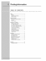
TABLE OF CONTENTS
[]
[]
[]
[]
[]
[]
[]
[]
[]
[]
[]
Safety ...................................................................
2
Definitions
..........................................................
2
ImportantSafetyInstructions..............................2
SafetyPrecautions
.............................................
3
Preparingfor mnstaJlation..................................7
%rifying PackageContents...............................
7
GasSupplyRequirements.................................
7
Gasand ElectricRequirements
Table................7
ElectricalPowerSupplyRequirements..............8
Gasand EiedHcaiRough-in..............................9
Cabinet!Counterop
Preparation.......................10
OveralDimensions..........................................
12
installingtheAnti-TipBracket...........................13
GasRegulatorandElectrical
ConduitLocation..............................................
16
mnstallation
........................................................
17
installingthe RangeBackguards.....................17
Removingthe Door(s).....................................
18
Reinstallingthe Door(s)...................................
18
MakingtheElectricalConnection.....................19
Makingthe GasConnection.............................22
InstallingtheRange.........................................
23
InstallingtheBurnerComponents....................23
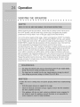
Operation ...........................................................
24
VerifyingtheOperation....................................24
[]
[]
[]
[]
[]
[]
[]
[]
[]
[]
[]
for
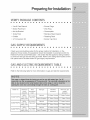
VERIFYPACKAGECONTENTS
[]
[]
[]
[]
[]
[]
[]
[]
[]
[]
[]
[]
• Use & Care Manual
[]
[]
[]
[]
[]
• Wok Ring
Anti-tip
• Simmerplate
Bracket
• Grate Pack
• Stainless
Steel Cleaner
• Griddle
o Roasting
Rack
Kit
[]
[]
[]
[]
[]
[]
[]
[]
[]
[]
, Burner Cap Pack
GAS SUPPLYBEQU
[]
[]
• Burner Rings
Broiler Pan/Insert
• LP Conversion
[]
[]
[]
[]
[]
[]
MENTS
[]
[]
[]
[]
[]
[]
[]
[]
[]
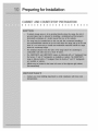
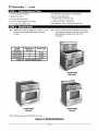
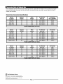
Check your local building codes for the proper method of installation. In the
absence of local codes, this appliance should be installed in accordance with the
National Fuel Gas Code ANSI Z223.1. Be certain that the appliance being installed
is correct for the gas service being provided. Refer to the rating label located on the
kick panel and/or the table below for gas supply requirements.
GAS AND ELECTRICREQUIREMENTSTABLE
[]
[]
[]
[]
[]
[]
Refer to the following
Model
No,
[]
Electrica!
required
240-4
Wire VAC,
60Hz,
30A
240-4
E36DF76EPS
[]
Wire VAC,
60Hz, 30A
Wire VAC,
60Hz,
[]
[]
[]
Total
50A
Gas type
connected
load
26.4 Amps
(6.3 Kw)
26,4 Amps
(6.3 Kw)
44.2 Amps
(10.4 Kw)
[]
[]
[]
[]
on gas and electric
Manifold
pressure
[]
[]
[]
[]
requirements.
Minimum
gas
supply
pressure
Natural
Liquid
Propane
Natural
Liquid
240-4
E48DF76EPS
[]
table for more information
circuit
E30DF74EPS
[]
Propane
Natural
Liquid
Propane
4" Water
Column
5" Water
10" Water
Column
11" Water
4" Water
Column
5" Water
10" Water
Column
11" Water
4" Water
Column
5" Water
10" Water
Column
11" Water
Column
Column
Column
Column
Column
Column
[]
for
ELECTRICAL POWER SUPPLY REQUREMENTS
[]
[]
[]
[]
[]
[]
[]
[]
[]
[]
[]
[]
[]
[]
[]
[]
[]
[]
[]
[]
[]
[]
It is the owner's responsibility
to ensure that the electrical connection of this
appliance is performed by a qualified electrician. The electrical installation,
including minimum supply wire size and grounding, must be in accordance with the
National Electric code ANSIiNFPA 70- 1993* (or latest revision) and local codes and
ordinances.
*A copy of this standard
National
Fire Protection
1 Batterymarch
Park
Quincy, Massachusetts
may be obtained
from:
Association
02269-9101
The correct voltage, frequency, and amperage must be supplied to the appliance
from a separate, grounded, circuit that is protected by a properly sized circuit
breaker or time delay fuse.
Refer to the Gas and Electrical
Requirements
Table on page 7.
for
@ASAND ELECTRiCaLR@U@Ho H
[]
[]
m
m
[]
[]
[]
[]
[]
[]
[]
[]
[]
[]
[]
[]
[]
[]
[]
[]
[]
[]
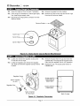
A manual shut valve must be installed in the gas piping, external to the appliance,
for the purpose of turning on or shutting off gas to the appliance. Plan the location
of the range and the gas supply to allow access to the valve when the unit is
installed. Access to the remote circuit breaker panel/fuse box, with the range in
place, must also be allowed for in the installation. Any openings in the wall behind
the appliance and in the floor under the appliance must be sealed.
Both the gas supply piping and shut-off valve, and the electrical junction box/
receptacle must be located so they do not interfere with the range when it is
installed. In addition, the junction box must be located so the range can be removed
for service when the conduit supplied with the unit is attached to the junction box.
Do not lengthen the conduit or wiring provided with the range.
All dimensions
shown are based on standard
American
cabinets
36 inches
(914mm) high at the finished countertop by 24 inches (610mm) deep, with a 25
inch (635mm) overall countertop depth. When installing the range into nonstandard
cabinets, minimum clearances shown in the diagrams on page 11 must be
maintained.
Carefully
check the location where the range is to be installed.
For best
performance,
the range should be placed away from drafts that may be caused
doors, windows and HVAC outlets.
by
for'
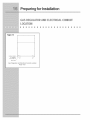
CABINETAND COUNTE ©P PREPARATION
[]
[]
[]
[]
[]
[]
[]
[]
[]
[]
[]
[]
[]
[]
[]
[]
[]
[]
[]
[]
[]
[]
for
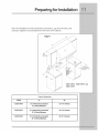
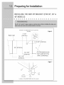
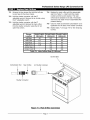
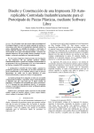
Plan the installation so that the electrical connection, gas shut=off valve, and
pressure regulator are accessible from the front of the cabinet.
Figure 1
(330ram)
10" (254mm) Min.
• to combustLble side
wails above the range
(both sides)
Minumim
25"
(635mm)
E30DF74EPS, E36DF76EPS and
E48DF76EPS
Cutout Dimensions
ModeJ
"A....
B"
E3ODF74EPS
36"(914mm}Recommended
30"(762mm}Minimum
301/16" (764mm}
E36DF76EPS
42" (1067mm)Recommended
3d' (914mm)Minimum
361/16" (914mm)
E48DF76EPS
54" (1372mm}Recommended
48"(1219mm}Minimum
481/8" (1222mm}
for
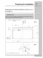
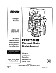
OVERALLD MENS ONS
[]
E36DF76EPS
--30
29 I/8"
--28
-26
//8"
[]
[]
[]
and E48DF76EPS
Side View
3/8" (772 ram}
--
[]
[]
[]
[]
[]
[]
[]
[]
[]
[]
[]
[]
[]
[]
[]
[]
[]
Overall Dimensions
Figure 2
Handle
(740 ram}
(714 ram)1/2"
[673
mm)
font
Edge
Face
of Con[rol
Rear
of Bulllnose
panel/Oven
of Corffrol
panel/Oven
Door
Door
24" (68 n!m)
Back _ua!d
3"
(79 mm)
9" (229 ram)
Back
uad
Backguord
37" (9
, rf'm)
to
35 3/4'
i
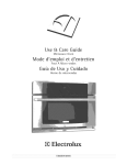
E30DF74EPS Overall Dimensions
Side View
_,
Figure 3
HANDLE
28 ]/4'
[718 1mini
27 3/8"
[693.7mm]
25 5/8"
[652 lmm]
24 1/8"
[6125mini
_.
FRONT
EDGE
OF
BULLNOSE
FACE
OF
CONTROL
PANEL
REAR
OF
CONTROL
PANEL
6" [I 52MM
1 BACKSPLASH
7"
[940mm]
to
35=3/4"
[90ti_r"_]
T
[]
for
IISTRLLIIQ THE AITI-TII BRACKET(FOR _", S8'=&
18'=IODELS}
[]
[]
[]
[]
[]
[]
[]
[]
[]
[]
Installation
All
Dimensions
J
are
[]
[]
of E30DF74EPS
[]
[]
[]
Anti-Tip
[]
[]
[]
[]
[]
[]
Figure4
Bracket
BASE
from
Cabinet Only
(Not Counferfop)
Location
[]
of the E30DF74EPS
30 1/16"
(122]mm}
Anti-Tip
FigureS
Bracket
\
\
\
\
\
REAR
Anti-tip bracket
location on left
rear leg
Pc÷
°
for
IISTRLLII@ THE RITI-TIP B_OKET iFOR _'=, 38'=&
41,=IOIELS}
[]
m
[]
[]
[]
[]
[]
[]
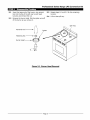
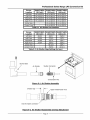
Installation of E36DF76EPS
Top View
[]
[]
m
[]
[]
[]
m
[]
[]
[]
[]
Anti-Tip Bracket
Figure 6
7 1/2"
Back wall
(191mm)
24" (610mm 1
I
Dimensions
j 18 1/32"
i (458mm)
36 1/16"
are
from Cabinet Only
(Not Countertop)
(916mm)
Figure 7
Rear
"_
Left
.......... Rear
Leg
Leveler
5/16- 18x2
or Equivalent
Location
of the E36DF76EPS
Anti-Tip
Leveler
[]
[]
for
IISTRLLIIQ THE AITI-TIP BRACKET(FOR _", 18'=&
18'=IOIEL$}
[]
[]
m
m
Installation
[]
m
[]
[]
[]
of E48DF76EPS
[]
Anti-Tip
m
m
[]
[]
m
[]
[]
m
m
[]
E
Bracket
TopView
Figure 8
13 5/16"
(339mm)
BACK
4 9/16"
(115mm}
t
WALL
L!,
j
I
J
'
1
1
1
1
1
1
1
1
1
All Dimensions "
are from
Cabinet Only
(Not Counfedop)
L
48 1/16"
(1221mm)
Figure 9
Rear
Leg
Location
of the E48DF76EPS
Anti-Tip
Leveler
"
Leveler
5/16 - 18 × 2
or Equivalent
for
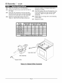
@ASR
[]
Figure 10
[]
[]
U_T©R AND ELECTRICAL
C@N _T
[]
[]
[]
Power cord /
Regulator
[]
[]
[]
[]
[]
[]
[]
[]
[]
[]
[]
[]
....................................................................................................................................................
Factory installed j
3/4"regulator
(1/2" supply ok)
Gas
[]
and
Electrical
Rear View
Conduit
Location
[]
[]
[]
38 & 48
NSTALUN@ THE
BACKGUARDS
©PT @NAL
NGE
[] [] [] [] [] [] [] [] [] [] [] [] [] [] [] [] [] [] [] [] [] []
Your EtectroluxIconTM range was shipped with a backguard inplace.These
instructions cover the installation of one of the optional backguards.
mnstaHing the Range
1.
Remove
2.
To avoid scratches,
Optiona_
the backguard
Backguard:
from its box.
place small scraps of thin cardboard
the side panels where the backguard
on the rear of
will make contact.
With the
assistance of at least one other person, carefully lift the backguard and
place down on to the range top. Special attention should be given to the
lower flange in front of the backguard, which must fit between the
stainless
steel side panels.
3.
Fasten the provided
4.
Connect
screws
through
the gas line to the regulator.
the rear flange.
Reposition
and attach the access
panel or the back cover if the entire back cover was removed.
5.
You are now ready to continue with the range installation.
Figure 11
Figure 12
BackguarU
Backguard
(36"
range
Installation
shown)
Backguard
(48"
range
Installation
shown)
.....
{
{: {
{:
{{:{{??{
::
{{
{
Open the door to its fully opened
position.
Rotate the catch over the retaining
arm
on each hinge. Lift the oven door to about a 30 degree angle from the horizontal
_osition. Pull the door away from the oven while continuing to lift.
Figure 13
::::::
::::: :::
....
: :: :: :: :: :: :: :: :: :: :: :: :: :: :: :: :: ::
..........................................................................................................................................
To remove
oven door,
rotate catch
as shown.
/_
Removing
the Oven
Door
REo_STALL_HG
THEOVEHBOOR{S}
[]
[]
[]
[]
[]
[]
[]
[]
[]
[]
[]
[]
[]
[]
[]
[]
[]
[]
[]
[]
[]
Grasp the oven door on opposite sides and lift it until the door hinges are aligned
with the openings in the oven frame. Holding the door at about a 30 ° angle from the
horizontal, slide the hinges into the openings until the bottom hinge arms drop fully
into the hinge receptacles. Lower the door to the fully opened position, and then
rotate the two hinge catches toward the oven.
Open and close the door completely
Peel off the protective
to ensure that it is properly
layer of plastic that covers the door panel.
installed.
[]
MAK H@THE ELECTRICALCONNECTION
[]
[]
m
[]
m
m
[]
[]
m
[]
m
[]
m
[]
[]
[]
[]
[]
[]
m
[]
[]
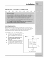
Grounding mnstcuctions
This appliance
must be electrically
grounded.
With the range positioned
directly in front of the cabinet cutout, feed the appliance conduit to the electrical
junction box. Then, depending upon Focal codes, utilize one of the following
techniques to connect the appliance to the electrical power supply:
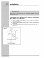
Connecting
to a Four-Wire
Electrica_ System
1. Separate the green and white appliance wires.
2.
3.
Connect the white appliance wire to the
neutral (white) supply wire in the junction
box.
Connect
the black appliance
Figure 14
Cable from
power supply
wire to the
black (L1) power supply wire in the
junction box.
4.
Connect the red appliance wire to the red
(L2) power supply wire in the junction box,
5.
Connect the green appliance wire to the
green house grounding wire in the junction
box.
Conduit from
appliance
Connecting
four-wire
the appliance
to a
power supply
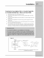
Connectingthe GreenAppliance Wireto the Neutral(White)Supply
Wire = WhereLocal CodesPermit
Figure 15
1
Connect the green and white appliance
wire in the junction box.
2
Connect the black appliance
junction box,
3
Connect the red appliance
junction box.
Cable from
power supply
RED
GREEN
RED
Wire
nut
(3 places)
Conduit from
appliance
Connecting
the appliance
to a
three-wire
power supply
wires to the neutral (white) supply
wire to the black (L1) power supply wire in the
wire to the red (L2) power supply wire in the
Connectingthe GreenAppliance Wireto a GroundedSupply Wire
or a GroundedColdWaterPipe= WhereLo_l Codes Permit.
1
Separate
2
Connect the white appliance
junction box.
the green and white appliance
wire to the neutral
wires.
3
Connect the black appliance
junction box.
wire to the black (L1) power supply wire in the
4
Connect the red appliance
junction box.
5
Connect the green appliance wire to a grounded
box or to a grounded cold water pipe.
6
If connecting to a grounded cold water pipe, a separate copper grounding
wire (No. 10 minimum) must be connected to a grounded cold water pipe
(white) supply wire in the
wire to the red (L2) power supply wire in the
by means of a clamp and then to an external
supply wire in the junction
grounding
connector
screw.
Figure 16
Cable from
power
supply
No. 10 (minimum)
copper
grounding
wire
box
copper
RED
GREE
No 4_
wire
I WHITE
WHITE
BLACK
Metal
_Wire nut
Junction
(4 places)
Conduit
from
appliance
Connecting
the appliance
ground to a grounded
or grounded
cold water pipe
junction
box wire
M£K NG THE G£S C©NNECT ON
[]
[]
[]
[]
[]
[]
[]
[]
[]
[]
[]
[]
[]
[]
[]
[]
[]
[]
[]
[]
[]
Before sliding the range into the cabinet, connect a flexible gas connector to the
gas shut-off valve previously installed on the stub out. The gas valve must be
turned off dunng installation. Connect the flex connector to the pipe fitting at the
right rear of the range.
[]
Measure from the floor to the countertop and adjust the leveling legs as required to
position the top frame at the desired height, based on the cabinet and countertop
installation. Carefully slide the range into position in the cutout. The rear anti4ip leg
should engage the anti4Jp bracket.
NSTA NO THEBURNERCOMPONENTS
[]
[]
m
m
m
m
[]
[]
[]
[]
m
m
m
[]
[]
[]
[]
m
m
m
m
Remove the brass burner rings, porcelain burner caps, and porcelain gates from
their shipping packages. Place each burner ring onto its corresponding
burner
base, being certain that the four alignment tabs slide into the matching notches in
the base. Set each porcelain burner cap on top of its corresponding
burner ring.
Place each grate onto the top frame, being certain that the rubber feet are
positioned in the locating dimples.
V
[]
THE @P AT ©N
[]
[]
[]
[]
Before beginning
[]
[]
[]
[]
the test procedure,
[]
[]
[]
[]
[]
[]
ensure that all cooktop
[]
[]
[]
[]
[]
[]
control valves are in
the "OFF" position, and all burner rings, burner caps, and grates are propedy
positioned on the top frame. Turn on the gas supply at the shut-off valve.
Turn on the power supply to the range. Select a temperature of 350°F by rotating
the temperature control knob to "350" and selecting "BAKE" with the oven selector
knob. Rotate each knob to the "Off" position to stop the heating process. For model
E48DF76EPS,
repeat this test procedure with the companion oven. Test each top
burner separately by pressing and turning one control knob at a time
counterclockwise
to the "HIGH" position. All ignitors will spark continuously, but only
the burner with gas flowing to it will ignite. (It will take approximately
4 seconds for
ignition to occur, at which time the ignitors will stop sparking. If ignition does not
occur within 4 seconds, turn off the knob, wait for at least 2 minutes to allow any
gas to dissipate, then repeat this ignition test.) The control knob can then be rotated
counterclockwise
from "HIGH" to "LOW" to adjust the flame height progressively.
Repeat the ignition test for all burners. When installed properly, the flame will be
steady and quiet. It will also have a sharp, blue inner cone that will vary in length
proportional
to the burner size.
[]
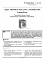
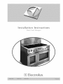
ICON
Professional
series
Liquid Petroleum Gas (LPG) Conversion
Instructions
Kit
Freestanding Range Models:
E30DF74EPS, E36DF76EPS, E48DF76EPS
Model E3ODF74EPS shown
----_ WARNING:
_
This conversion kit shall be installed by a qualified service agency in accordance
with the manufacturer's
instructions and all applicable codes and requirements
of
the authority having jurisdiction,
If the information
in these instructions is not
followed exactly, a fire, explosion, or production of carbon monoxide may result
causing property damage, personal injury, or loss of life, The qualified service
agency is responsible for the proper installation of this kit, The installation is not
proper and complete until the operation of the converted appliance is checked as
specified in the manufacture's
instructions supplied with the kit,
CAUTION"
•
Before proceeding with the conversion, shut off the
gas supply to the appliance prior to disconnecting the
electrical power.
•
Do not reconnect electrical power until all leak tests
have been performed.
_
•
Only a qualified service technician
service this appliance.
should convert or
•
Be sure the unit is unplugged
proceeding with the conversion.
and coot before
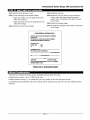
IMPORTANT:
Read and save these instructions for future use and
for use by the building inspector.
•
•
The range will not operate properly unless the correct
sized orifices and air shutters are installed for each
burner and valve and the air shutters for each burner
are properly adjusted.
The range will not operate properly unless the
regulator is converted according to these instructions.
After installing the LPG orifices, be sure to keep the
original factory installed orifices for future conversion
back to natural gas. See page 12 for instructions on
how to convert this appliance to nature gas from
LPG.
Pa_ No> 65558 Rev. 1-4
[] Electrolux
I Jc o N
• 1/8" flat blade screwdriver
* Thread-locker
• Needle-nose pliers
• 10 mm open end wrench
* Burner ring removal tool
(provided with conversion kit)
• 6" and 8" long adjustable wrenches
* U-tube manometer (calibrated)
• 6" (or 150 mm) pocket rule
° Leak detector: Gas or bubble forming fluid
2-1
Identify the model number from Table 2-1. How
the oven is equipped determines the model
number.
Model
Number
Number of
Burners
Use the model number to identify the correct
orifice sizes, shutter part number, and shutter
gap settings throughout the rest of this
procedure.
Oven Type
E30DF74EPS
4
Sinc_le
E36DF76EPS
E48DF76EPS
6
6
Sincjle
Double
Table 2-1
2-2
(Loctite 242 or equivalent)
Model Identification
E48DF76EPS
(48-Inch)
E36DF76EPS
E30DF76EPS
36-Inch
30-Inch
Note: Styling and size of backsplash may vary.
Fiqure
2-1
Model
Identification
Page 2
Professional Series Range LPG Conversion
LPG Conversion
Kit for Models
E36DF76EPS
and E48DF76EPS
Kit Part Number:
(36 and 48-Inch)
700147-1
Part Number
Description
65481
65480
BAGr PLASTIC
LABEL, CONVERSION INFORMATION
86007
TOOL, REMOVAL, BUNRER RING
1
65558
INSTALLATION INSTRCTIONS r LPG CONVERSION KIT
1
76125*
O-RING r BYPASS
ORIFICE, BYPASS, .0048MM
6
92125-48
92125-61
ORIFICE, BYPASS, .0061MM
4
72427-86
ORIFICE r MAINr .0086MM
ORIFICE, MAIN, .0112MM
2
ORIFICE, MAIN, .0118MM
* Provided assembled to the bypass orifices
2
72427-112
(_uantity
1
2
2
2
72427-118
LPG Conversion
Kit for Model
E30DF74EPS
(30-Inch)
Kit Part Number:
700147-2
Part Number
Description
65481
BAGr PLASTIC
65480
2
86007
LABELr CONVERSION INFORMATION
TOOL, REMOVAL, BUNRER RING
65558
INSTALLATION INSTRCTIONS r LPG CONVERSION KIT
1
76125*
O-RING r BYPASS
ORIFICE, BYPASS, .0048MM
4
92125-48
92125-61
ORIFICE, BYPASS, .0061MM
3
72427-84
ORIFICE r MAIN r .0084MM
1
ORIFICE r MAIN r .0111MM
ORIFICE, MAIN, .0118MM
2
72427-111
72427-118
_uantit_
1
1
1
1
* Provided assembled to the bypass orifices
Page 3
Kit
[] Electrolux
1-'II / :1_
1
[ ic o N
U i_ ,B1 i_l _.1 i[, [=i [,] ile[,] itVL_i_-1[,] i
3-1
Move the range out from the wail, if necessary.
3-4
Remove the grates from the cooktop.
3-2
If the range is connected to a natural gas supply
line, close the gas supply valve.
3-5
Remove all of the burner caps and burner rings
from top of the burner heads.
3-3
Disconnect the range power connector from the
electrical outlet.
Burner Cap
Burner
Burner Head-
Fiqure
3-1
Grate,
Burner
Cap and
4-1
Locate and remove the regulator access panel
on the back of the range.
4-2
Locate the regulator and remove the regulator
cap. Make sure that the regulator spring remains
in place.
Burner
Rinq
Removal
4-3
Remove the spool from the cap and insert the
opposite side. The large end of the spool must
insert into the regulator first for LPG operation.
4-4
Replace the cap. The access panel will be reinstalled later.
Regulator Spring
Access panel for
E36DF76EPS &
E48DF76EPS
Spool: Direction
for LPG XXX
Regulat°r Cap X4@
Access panel for-_D
E30DF74EPS
.....
°-
....
-j
°
r.
_'X
Spool: Direction
for natural gas
Fiqure
4-1
o
Back of range
Requlator
Page 4
Conversion
Professional Series Range LPG Conversion
5-1
Insert the large end of the burner ring removal
toot into the top of the left rear burner head.
Unscrew and remove the nut.
5-2
Remove the burner head, Slip the igniter wire off
of the burner as you remove it.
5-3
Repeat steps 5-1 and 5-2 for the remaining
burners.
5-4
Lift out the spill tray.
Spill Tray
Removal Toot
Igniter
/
Retaining Nut
Burner Head
Fiqure
5-1
Burner
Head
Page 5
Removal
Kit
[] Electrolux
6-1
6-2
[ Ic o N
Make sure all knobs are in the off position,
Remove all of the burner knobs from the front of
the range,
6-3
Insert the 1/8" screwdriver into the valve stem
hole for the left rear burner, Unscrew the bypass
orifice from the right side of the valve assembly.
6-4
Identify the appropriate bypass orifice from
Table 6-1. Match both the model number and
Burner
Location
Left: Rear
E30DF74EPS
(30-Inch)
61
the burner location, The bypass orifice size is
stamped on its head,
6-5
Insert the bypass orifice and the attached o-ring
into the right side of the valve with the needle
nose pliers. Tighten into place with the 1/8"
screwdriver.
6-6
Repeat steps 6-1 through 6-5 for the remaining
burner valves,
6-7
Replace the knobs.
E36DF76EPS
(36-Inch)
61
E48DF76EPS
(48-Inch)
61
48
48
48
Right Rear
61
48
48
61
61
61
61
61
61
61
I
Left Front
i
Ric)ht Front
Center Rear
Center Front
Table B-1 Bypass Orifice Sizes (x 100 rnrn}
Valve Stem
Fiqure
6-1
Bypass
Orifice
Page 6
Conversion
Professional Series Range LPG Conversion
7-1
Remove the two screws that hold the left rear
burner base to the stove chassis.
7-2
Hold the shutter connector with the 8"
adjustable wrench. Remove the air shutter using
the 6" adjustable wrench.
Hold the shutter connector with the 8"
adjustable wrench. Remove the main orifice
from the shutter connector using the 10 mm
open-end wrench.
Replace the main orifice with the appropriate
size from Table 7-1, Match both the model
number and the burner location. The main
orifice size is stamped on its side, The shutter
and the burner base will be re-assembled after
pressure testing,
7-5
Check to make sure that the compression nut is
tightened into the back of the shutter connector.
7-6
Repeat steps 7-1 through 7-5 for the remaining
burners.
Burner
E30DF74EPS
E36DF76EPS
Location
Left Rear
_30-Inch)
84
_36-Inch)
112
E4BDF76EPS
_48-Inch)
112
Left Front
111
86
86
Right Rear
111
86
86
118
112
118
112
118
118
118
I
7-3
7-4
i
Ricjht Front
Center Rear
Center Front
Table 7-1
Main Orifice Sizes (X 100 mrn)
Burner Base
\
Main Orifice
Compression Nut
Air Shutter (remove)
t
Shutter Connector
Fiqure
7-1
Kit
Main Orifice
Page 7
Conversion
[] Electrolux
I-'i
/ ;I "i,i; -I
8-1
_/r-I_ i_o] i iil
[ Ic o N
"-JiC;_-!-I ! I iC;II [_i_.
Connect the U-tube manometer to the LPG
8-5
Hake sure all knobs on the front of the range
are in the off position.
supply line.
8-2
With electrical power to the range disconnected.,
open the LPG supply valve.
8-6
Connect the U-tube manometer to the left rear
burner's main orifice with 3/8" surgical tubing.
8-3
Verify that the pressure is above 11 inches water
column (WC) and below 1/2PSI. Consult the
factory if the pressure is not within the above
limits.
8-7
Open the LPG supply valve. Turn on the left rear
burner. The manometer should read 10 inches
WC +/- 1/2inch. Contact the factory if the
pressure does not meet specifications.
8-4
Close the LPG supply valve. Connect the range
to the LPG supply line.
8-8
Turn off the burner and the gas supply valve.
Place end of tube over main orifice
Fiqure
9-1
9-2
8-1
Pressure
Determine the appropriate air shutter part
number for the left rear burner from Table 9-1
on page 9. Be sure to match the model number
and burner location. The shutter part number
appears on its side.
Thread the air shutter onto the left rear shutter
connector about 6 turns (see Figure 9-1).
9-3
Reinstall the burner base (see Figure 9-1).
9-4
Measure the gap between the end of the shutter
connector and the opposite end of the shutter
opening with the pocket rule (see Figure 9-2).
9-5
Compare the measured gap to the gap listed in
Table 9-2 for the appropriate model number and
the burner location.
9-6
Test Set-up
Hold the shutter connector with the 8"
adjustable wrench, Adjust the air shutter using
the 6" adjustable wrench until the gap is to
within 1/16" (1,6 mm) of the gap indicated in
the table,
9-7
Secure the shutter with thread-locker,
9-8
Repeat steps 9-1 through 9-7 for the remaining
burners,
9-9
Check to make sure that the compression nut is
tightened into the back of each shutter
connector.
Page 8
Professional Series Range LPG Conversion
Burner
Location
E30DF74EPS
(30-Inch)
E36DF76EPS
(36-Inch)
E48DF76EPS
(48-Inch)
Left Rear
HN A-0053-E
HN A-0053-E
HN A-0053-E
Left Front
HN A-0052-E
HN A-0052-E
HN A-0052-E
Right Rear
HN A-0053-E
HN A-0052-E
HN A-0052-E
HN A-0053-E
HN A-0053-E
HN A-0053-E
HN A-0053-E
HN A-0053-E
HN A-0053-E
HN A-0053-E
/
i
Right Front
Center Rear
Center Front
Table 9-1 Air Shutter
Part Numbers
Burner
E30DF74EPS
E36DF76EPS
Location
Left Rear
_30-Inch)
.36/9.2
_36-Inch)
.38/9.7
_48-Inch)
.39/9.8
Left Front
.34/8.6
.27/6.9
.12/3.1
Ricjht Rear
.35/8.9
.29/7.4
.18/4.7
Ricjht Front
Center Rear
.37/9.4
.39/9.9
.40/10.0
.38/9.6
.38/9.7
.39/9.8
.40/10.1
Center Front
Table 9-2 Air Shutter
Air Shutter
E4BDF76EPS
Gaps Settincjs (in/mm)
Shutter Connector
1
Buiner Base
t
Compression Nut
Fiqure
9-1
Air Shutter
Assembly
Shutter Gap _
Apply thread-locker
here
End of shutter connector"
Fiqure
9-2
Air Shutter
Reassembly
Page 9
and Gap Ad|ustment
Kit
[] Electrolux I nc o N
10-1
Make sure that all knobs on the front of the
10-4
range are in the off position.
10-2
With electrical power to the range disconnected.,
open the LPG supply valve.
10-3
Using a gas leak detector or bubble forming leak
detection fluid, check the following for leaks:
• LPG gas supply connection
• All manifold connections
Re-assemble the burner heads, burner head
nuts, burner rings, and burner caps without the
spill tray in place. Be sure the igniter wire is
connected to each burner head.
10-5 Connect the range to the electrical outlet.
10-6 Turn each burner on HIGH, one at a time.
Check for leaks around the valves (including the
bypass orifice) and the burner lines.
• All valve connections
• Bypass orifices
Igniter
J
\
Burner Head
Connect igniter wire here /
Fiqure
[-'Jl/_l_ ill
_
10-1
Iqniter
Connection
_
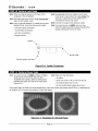
11-1 Turn each burner on HIGH and then off again,
several times. If the flame does not light
repeatedly and rapidly, check for obstructions
between the igniter and the burner head (see
Figure 10-1).
11-2 Make sure that the flame:
• Is stable.
• Does not waver or lift up from the burner.
• Is predominatety blue in color.
• Is not predominatety yellow at the tips.
If the flame does not have the correct appearance, check the shutter gap settings (see STEP 9). If adjusting the
air shutters will not correct the problem, contact the factory.
Fiqure
11-1
Examples
of a Normal
Page 10
Flame
Professional Series Range LPG Conversion
Kit
12-1 Wait for all the burners to coot.
12-4 Install the spill tray.
12-2 Fill out and apply the conversion labels:
12-5 Replace the burner heads, burner head nuts,
burner rings, and burner caps. Be sure the
igniter wire is connected to the igniter for each
burner head.
° Apply one where it can be easily read on the
floor of the chassis.
° Apply the other next to the rating label on the
back of the range.
12-6 Install the cooktop grates.
12-7 Re-install the regulator access panel on the back
of the range.
12-3 Remove all of the burner heads.
CONVERSION INFORMATION
AFFIX THISLABELAS CLOSE AS POSSIBLETO THE _(ISTING
RATING PLATE.
FOR MODEL NO. RATINGS AND MANIFOLD PRESSURE
INFORMATION: SEEORIGINAL NAME PLATE.
GAS SUPPLYTYPE:
NATURAL
GAS
FI
u,
[]
CONVERSION KITP/N
THISAPPLIANCE WAS CONVERTED ON
DAY/MONTHpfEAR
TO.
.GASWnHrJTNO,
(INStALL_)
(COMPANY
NAME)
WHICH ACCI_P3 THERESPONSlBIIJTYTHATTHiS CONVERSION
HAS BEENPROPERLYMADE.
Fiqure
12-1
Conversion
Label
The Electrotux Professional Series range is equipped with two types of burners:
° Sealed power burners - up to :[7,000 BTU per hour
° Sealed precision burner(s) - up to 8500 BTU per hour (smaller in size than the power burner)
For elevations above 2000 feet, the burners ratings will be reduced at the rate of 4% for each 1000 feet above
sea level.
Page 1:[
If it is necessary
to returnthe rangeto naturalgasservice,repeatallof thestepsinthis procedure
usingthe
partsthat havebeenremoved.Usethe chartbelowto determine
the orificesizes,shuttergaps,andthe air
shutterpartnumbers.
Natural
Gas Conversion
Specifications
Burner
Bypass
Main
Air Shutter
Air Shutter
Location
Orifice
Left Rear
81
Orifice
Part No.
Gap _IN/MM_
184
HN A-0053-E
.37/9.5
Left Front
72
140
HN A-0052-E
.34/8.6
Right Rear
81
184
HN A-0053-E
.35/8.9
Ric_htFront
81
188
HN A-0053-E
.37/9.4
Air Shutter
Part No.
Air Shutter
Gap
Model E30DF74EPS
(30-Inch)
Burner
Location
Bypass
Orifice
Main
Orifice
Left Rear
Left Front
81
72
184
133
HN A-0053-E
HN A-0052-E
.37/9.5
.30/7.6
Ric_htRear
72
133
HN A-0052-E
.33/8.4
Ric_htFront
Center Rear
81
81
184
196
HN A-0053-E
HN A-0053-E
.37/9.4
.3_ 9.6
Center Front
81
196
HN A-0053-E
.37/9.5
Model E36DF76EPS
(36-Inch)
Burner
Bypass
Main
Air Shutter
Air Shutter
Location
Left Rear
Left Front
Orifice
81
72
Orifice
184
133
Part No.
HN A-0053-E
HN A-0052-E
Gap
.38/9.6
.35 8.8
Ricjht Rear
72
133
HN A-0052-E
.3C 7.7
Right Front
Center Rear
81
81
184
196
HN A-0053-E
HN A-0053-E
.39/9.9
.38/9.7
Center Front
81
HN A-0053-E
.37/9.5
196
Model E48DF76EPS
The Electrolux Group
USA • 250 Bobby Jones Expressway * Augusta, GA 30907
1-877-4electrolux
(1-877-453-5287)
• www.etectroluxusa,com
CANADA • 5855 Terry Fox Way • Mississauga,
1-800-688-4606
• www.electroluxca.cora
ON L5V 5E4
Page 12
(48-Inch)