1
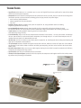
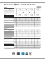
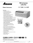
Value Place Cleveland Ohio Submittal Data
PACKAGED TERMINAL AIR CONDITIONERS AND HEAT PUMPS
WITH OUR DIGISMART® CONTROL BOARD & EMS
PTAC SPECIFICATIONS AND ACCESSORIES CATALOG
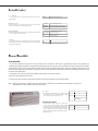
First-Year Warranty: Parts & Labor on entire unit
Second through Fifth Year: Parts & Labor on certain sealed system components
Second through Fifth Year: on certain functional parts only
* Complete warranty details available at www.amana-ptac.com.
p
MC-DPTAC
www.amana-ptac.com
Amana® is a trademark of Maytag Corporation or its related companies and used under license to Goodman Company, L.P. All rights reserved.
3/12
Supersedes 2/12
STANDARD FEATURES
(QHUJ\(IÀFLHQFLHV:LWK((5VXSWRDQG&23VXSWRRXUXQLW·VKLJKHIÀFLHQFLHVPD\TXDOLI\\RXIRUPDQ\RIWKHUHEDWHV
offered by electrical power companies.
4XLHW2SHUDWLRQ2XU37$&KDVEHHQUHGHVLJQHGWREHWKHTXLHWHVW37$&ZH·YHHYHUEXLOW7KHXQLW·VVWDWHRIWKHDUWGHVLJQDQG
FRQVWUXFWLRQSURYLGHDTXLHWHQYLURQPHQWDOORZLQJJXHVWVWRHQMR\SHDFHIXOVOHHSÀOOHGQLJKWV
Two fan motors (indoor/outdoor)
,QGRRUWDQJHQWLDOIDQIRUTXLHWRSHUDWLRQ
STC of 28
$VVHPEOHGLQWKH86$IRU\HDUV assembled at our plant in Fayetteville, TN, using Goodman resources including
engineering, production, and testing.
,QFUHDVHG'HKXPLGLÀFDWLRQ&DSDFLW\ Maintain lower humidity levels in rooms while cooling them without the need
for expensive add-ons. As a result, guests feel more comfortable at higher temperatures, thus reducing cooling costs.
%XWWRQ7RXFK3DG Provides complete control to guests for in-room comfort
ZKLOHPDLQWDLQJHQHUJ\HIÀFLHQF\
<HDU/LPLWHG:DUUDQW\(QMR\RQHRIWKHPRVWFRPSUHKHQVLYHZDUUDQWLHVLQWKHLQGXVWU\VW<HDUSDUWVODERUQGWKURXJK
WK\HDUSDUWVODERURQFHUWDLQVHDOHGV\VWHPFRPSRQHQWVQGWKURXJKWK\HDURQFHUWDLQIXQFWLRQDOSDUWVRQO\)RU
complete warranty details, visit www.amana-ptac.com.
5XQ7HVWHG All units are 100% run tested at our plant in Fayetteville, TN, including leak checks during manufacturing and
again prior to shipment at the warehouse.
7зµ8QLW)URQW'HSWK Enhance valuable room space with our slim unit front, which has a sleek 7з” depth, one of the shallowest silhouettes in the industry today. In addition, to inhibit guest-tampering, the front can be secured to the chassis with a
hidden screw.
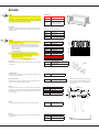
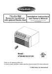
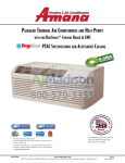
5HPRYDEOH&RQGHQVHU6KURXG$OORZVHDV\DFFHVVWRHQDEOHUHJXODUFOHDQLQJRIFRLOVZKLFKLVHVVHQWLDOWRPDLQWDLQXQLWHIÀFLHQF\
and protect the compressor for long unit life.
(DV\3XOO2XW)LOWHUV2XUÀOWHUVDUHZDVKDEOHDQGHDV\WRPDLQWDLQ
)LOWHU'U\HUIRU6HDOHG6\VWHP5HIULJHUDQW Standard in all units to protect the compressor and lengthen the life of the unit by removing moisture and preventing acid formation.
ÊÄãÙʽÊÙ
REMOVEABLE/CLEANABLE SHROUD FOR EASY
CLEANING
EASY PULL-UP FILTERS
FILTER DRYER
2
www.amana-ptac.com
MC-DPTAC
STANDARD FEATURES (CONT.)
&RQGHQVDWH'LVSHUVLRQ6\VWHP Our condensate dispersion system removes condensate from indoor cooling operation by throwing
ZDWHUGLUHFWO\RQWRWKHRXWGRRUFRLOIRUUDSLGHYDSRUDWLRQDQGLQFUHDVHGFRROLQJHIÀFLHQFLHV7KHVOLQJHUULQJRQWKHQHZ
enhanced fan draws water up and into the fan blades. This water is then atomized and evaporated into the atmosphere
through the condenser. Increased surface area from the coil allows more water to be evaporated on the sides of the coils and
helps to minimize condensate run-off.
)URQW'HVN&RQWURO(DFKXQLWFRPHVHTXLSSHGZLWKWKH'LJL6PDUWFRQWURODQGHQHUJ\PDQDJHPHQWVRIWZDUH:LWK'LJL6PDUW
using the optional RF antennae, all units can be wirelessly connected to a central hub for enhanced energy savings and
GLDJQRVWLFV$PDQDEUDQG37$&VDOVRKDYHDORZYROWDJHLQWHUIDFHFDSDELOLW\ZLWKDÀHOGVXSSOLHGIURQWGHVN212))VZLWFK
(See Page 4.)
5RRP)UHH]H3URWHFWLRQ When the unit senses temperatures of 40°F or below, the unit activates the fan motor and either the
electric resistance heater or the hydronic heater.
(DV\WRXVH&RQWUROV No complex controls to confuse your guests and create phone calls for your manager. Controls are easy to
read, understand, and activate. Our new 7-button control panel provided guests with complete control of the unit for their
LQURRPFRPIRUWZKLOHPDLQWDLQLQJRYHUDOOHQHUJ\HIÀFLHQF\
(DV\WR6HUYLFHZLWK2Q%RDUG/(''LDJQRVWLFV The main components are easily serviced and there is no guessing to determine the
problem with our easy-to-read diagnostics.
6WRQHZRRG5RRP)URQW2XU6WRQHZRRGURRPIURQWVWULNHVWKHEDODQFHEHWZHHQDWWUDFWLYHVW\OLQJDQGSUDFWLFDOGHVLJQ'LVWLQFtive contours and a modern appearance enhance the character of even the most luxurious room, while the sleek 7з” depth
maximizes usable space for your guests.
5HPRWH7KHUPRVWDW&RQWURO:KHQWKH'LJL6PDUWZLUHOHVVUHPRWHWKHUPRVWDWLVVHWXSERWKWKHUHPRWHWKHUPRVWDWDQGXQLWFRQWUROSDQHOFRQWLQXHWRFRQWUROWKHXQLWSURYLGLQJÁH[LELOLW\DQGKRPHOLNHV\VWHPFRQWURO,QVWDOODWLRQUHTXLUHVQRPRUHWKDQ
pressing two buttons. No need to run wires or make electrical connections.
5HPRWH7HPSHUDWXUH6HQVLQJ*XHVWVHQMR\XOWLPDWHFRPIRUWZLWKFRQVLVWHQWFOLPDWHFRQWURO:KHQWKHÀHOGLQVWDOOHGWKHUPLVWRU
(RTS03) is used, the unit-mounted thermostat is overridden to allow more accurate, internal wall-sensing of room ambient
temperature.
([WHQGHG+HDW3XPS+HDWLQJ Heat pump models will operate in the heating mode down to as low as 24°F outdoor ambient temperature.
=HUR)ORRU&OHDUDQFH7KHXQLWFDQEHLQVWDOOHGÁXVKWRDÀQLVKHGÁRRULIGHVLUHG6RPHDFFHVVRULHVGRQRWKDYH]HURFOHDUDQFH
6HFRQG)DQ2II'HOD\ The fan continues to run 30 seconds after the compressor has stopped in either cooling or heat pump
PRGHDQGDIWHUHOHFWULFKHDWKDVEHHQWXUQHGRII7KLVLPSURYHVHIÀFLHQF\E\GLVSHUVLQJWKHFRQGLWLRQHGDLURQWKHFRLOVLQWR
the room.
&RPSUHVVRU/RFN,Q This feature helps prolong the life of the compressor by preventing short-cycling. When the compres-sor is
VZLWFKHGIURP2IIWR2QEHFDXVHURRPWHPSHUDWXUHKDVULVHQRUIDOOHQEHORZWKHVSHFLÀHGOLPLWLWZLOOUHPDLQRQIRUDWOHDVW
4 minutes. If the temperature set-point is changed during this 4 minutes, the lock-in feature is overridden.
$XWRPDWLF(PHUJHQF\+HDW No more “my unit is not heating” complaints during the middle of the night. Heat pump units will
automatically switch over to electric resistance heat if the heat pump compressor system fails or if the heating load is greater
than the unit capacity.
&RQVWDQW)DQ0RGH Take advantage of each unit’s dual options — select continuous fan operation or cycle the fan ON and OFF
with the thermostat. Our new 7-button design allows guests to select fan performance while allowing the owner to have the
unit revert to the desired program of continuous fan or cycle with conditioning.
+LGGHQ9HQWLODWLRQ&RQWURO The ventilation control lever is hidden from the occupant's view to allow you to manage ventilation
UHTXLUHPHQWV
+LJK3UHVVXUH6ZLWFK Protects the unit from high pressure and damage to the unit, helping to ensure long unit life.
MC-DPTAC
www.amana-ptac.com
3
brings together our best PTAC ever with our best Energy Management Software and now integration with
3URSHUW\ 0DQDJHPHQW DQG )URQW 'HVN 0DQDJHPHQW 6RIWZDUH 5HGXFH 37$& HQHUJ\ FRQVXPSWLRQ E\ 25 025( WKURXJK
the power of the in-unit Energy Management System, programmable temperature set-back and limits combined. Reduce PTAC
PDLQWHQDQFHFRVWWKURXJKRXUDXWRPDWHGPDLQWHQDQFHQRWLÀFDWLRQV\VWHP,PSURYHGPDLQWHQDQFHVXVWDLQVHQHUJ\HIÀFLHQF\
((5DQGSURORQJV37$&OLIHNHHSLQJHTXLSPHQWUXQQLQJDWLWVGHVLJQHGHIÀFLHQF\OHYHODQGURRPJXHVWVPRUHFRPIRUWDEOH
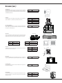
THE AMANA BRAND DIGISMART SOLUTION
IN-ROOM: “SELF-INSTALLABLE” WIRELESS PERIPHERALS
7KH'LJL6PDUW2FFXSDQF\6HQVRUFRPSOHWHVWKHLQURRPHTXLSPHQW7KLVLQIUDUHGVHQVRUFDQ
GHWHUPLQHLIWKHURRPLVRFFXSLHGRUHPSW\DQGZKHQHPSW\VLJQDOWKH37$&WRDGMXVWWKH
temperature to save energy based on programmable setbacks.
7KH'LJL6PDUW:LUHOHVV5HPRWH7KHUPRVWDWFDQPRXQWRQWKHZDOODQ\ZKHUHLQWKHJXHVWURRP
Battery powered and with its own wireless ability to communicate with the PTAC to maintain
room temperature. Best of all, no wires to run. The PTAC and Thermostat connect at the press of
a button and are permanently linked. The thermostat and PTAC work in-sync to display accurate
temperature.
7KH 'LJL6PDUW :LUHOHVV $QWHQQD LQVWDOOV LQVLGH WKH 37$& ZLWK D VQDSLQ FRQQHFWRU ,QVWDOOLQJ WKH DQWHQQD DOORZV WKH 37$& WR
FRPPXQLFDWHZLUHOHVVO\ZLWKRWKHUGHYLFHVLQWKHURRPDQGWRWKH'LJL6PDUWQHWZRUN
> 45,000+ rooms have had wireless installations since 2005
> Total wireless devices deployed to date – 120,000+
7KH$PDQDEUDQG'LJL6PDUW37$&ZLWKDQWHQQDFRPELQHGZLWKWKHVHOILQVWDOODEOHZLUHOHVV7KHUPRVWDWDQG2FFXSDQF\6HQVRU
JLYHWKHSURSHUW\RZQHUFRPSOHWHFRQWURORYHUWKHHTXLSPHQWVHWWLQJVDQGFDQUHGXFH37$&HQHUJ\XVDJHE\25025(
SITE-LEVEL —
CENTRAL WIRELESS CONTROLLER
!6LWHZLGH37$&&RQÀJXUDWLRQ
!6LWHZLGH37$&'LDJQRVWLFV
!)URQW'HVN6\VWHP,QWHUIDFH
> Email Reporting
> Internet Accessible Web User
Interface Enterprise
7KHVHVDYLQJVUHSUHVHQWHVWLPDWHGVDYLQJVRYHUWLPHDVFRPSDUHGWRWKHVDPH37$&PRGHOZLWKRXWWKH'LJL6PDUW(066\VWHPLQVWDOOHGDQGZHUHJHQHUDWHG
using general assumptions including energy loads, local weather averages and use of occupancy controls. Actual savings will vary according to actual use
KDELWVURRPVTXDUHIRRWDJHDQGKRZWKHXQLWLVLQVWDOOHG
4
www.amana-ptac.com
MC-DPTAC
ENTERPRISE — MULTIPLE WIRELESS CONTROLLERS
CENTRAL MONITORING AND
CONTROL OF MULTIPLE PROPERTIES
!'DWD:DUHKRXVLQJ
> Savings Analysis
> Email Reporting
> Virtual Metering
> Load Shedding
WEB-BASED, REAL-TIME MONITORING
AMANA® BRAND DIGISMART™ CONTROLLER:
All of the PTACs in the building can be managed through a single interface on a PC.
)($785(6 ,1&/8'( )XOO XQLW GHWDLOV IRU HYHU\ 37$& YLVLEOH IURP WKH IURQW GHVN RU KRPH RIÀFH DXWRPDWLF HPDLOV IRU 37$&
maintenance, ability to change all settings on the unit, and enhanced diagnostics. Monitor up to 170 PTACs, WIRELESSLY, with one
controller. Additional controllers can expand the network for additional rooms/properties.
!6\VWHP9HULÀFDWLRQ
> Global Setbacks
!(06&RQÀJXUDWLRQ
> Site Statistics
> Battery Notices
> Email Reporting
> Unit Health
> Unit Code Alerts
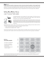
Temp Limiting – Each PTAC
FDQ EH FRQÀJXUHG ZLWK D KHDW
ing and cooling temperature
set-point limit.
Setbacks – Once a room is declared unoccupied by the occupancy sensor, the PTAC progresses through three different temperature
VHWEDFNVFRQÀJXUHGDVWKUHHGHJUHHDQGWLPHSDLUV$QH[DPSOHFRQÀJXUDWLRQLVOLVWHGEHORZ
1st: 2°, 30 mins – Setback the temp 2 degrees after 30 minutes
2nd: 4°, 1 hr – Setback the temp 2 more degrees after 30 more minutes
3rd: 8°, 3 hrs – Setback the temp 4 more degrees after 2 more hours
8QUHQWHG6HW3RLQWV²%\LQWHJUDWLQJZLWK\RXUSURSHUW\
V)URQW'HVN6\VWHPWKH37$&VZLOODGMXVWWRVSHFLÀFVHWSRLQWVZKHQQR
ORQJHULGHQWLÀHGDVUHQWHGLQWKHV\VWHP
MC-DPTAC
www.amana-ptac.com
5
NOMENCLATURE
#*
&
$%&
'
(
)
&(
* + , $# $$ $% $&
$'
(#&$$!&
$&9
#$&,'$#'
(#&(+"%
+"$$!&
(#&
$!
$&&$'$#&$()$#7$'(8
$-&$$&
<C
C<<<5
B<0
<E
E<<<5
B<0
+(+&'
=>
=><<<5
B<0
+'$!&
=A
=@<<<5
B<0
/&$#
$##'(+"%
+((
>
==A2B<02=
#(##
?
>?<5><D2B<02=
$-&#(
@
>BA2B<02=
%!$!&
&&
&#'$&"&
6@=<
'+%($@'##!%)!$&&
<<
$!(&(
=A
=4A >A
>4A ?A
A<
?4A 7>?<5><D8
."%!'3
?4C 7>BA8
=>?A<
<C??A
A4< =>?A<
<C?>A
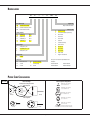
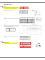
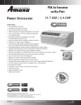
POWER CORD CONFIGURATION
133 units
3RZHU&RUG3OXJV
3RZHU5HFHSWDFOH&RQÀJXUDWLRQ
95DWLQJ3RZHU&RUG3OXJVZLWK/&','HYLFH
1(0$&RQÀJXUDWLRQ
G
NEMA6-15R; 250V receptacle,
used on 230/208V units
G
NEMA6-20R; 250V receptacle,
used on 230/208V units
G
20 amp
15 amp
30 amp
95DWLQJ3RZHU&RUG3OXJV
1(0$&RQÀJXUDWLRQ
G
20 amp
6
G
G
W
W
G
W
30 amp
www.amana-ptac.com
NEMA6-30R; 250V receptacle,
used on 230/208V units
NEMA7-20R; 277V receptacle,
used on 265V units
NEMA7-30R; 277V receptacle,
used on 265V units
All units come with factory-installed power cords.
$OOXQLWVOHVVWKDQYROWVFRPHZLWK/&',GHYLFH
MC-DPTAC
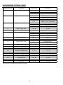
PRODUCT SPECIFICATIONS: PTC MODELS — COOLING/ELECTRIC HEAT (CONT.)
230/208 VOLTS
8 units
125 units
Dʽ¹, ϼ, Ͼ, Ͽ
Voltage ¹, ³
Capacity (BTU/h)
Amps Ϸ϶
tĂƩƐ Ϸ϶
EER
PTC
073G***XXX
230 / 208
7,700 / 7,700
3.5 / 3.5
PTC
093G***XXX
230 / 208
9,000 / 9,000
4.1 / 4.1
PTC
123G***XXX
230 / 208
11,700 / 11,500
5.6 / 5.6
PTC
153G***XXX
230 / 208
15,000 / 14,700
7.0 / 7.0
670/660
11.5/11.7
805/785
11.2/11.5
1135/1105
10.3/10.4
1500/1470
10.0/10.0
hÄ®ãó®ã«Êçã½ãÙ®,ãÙ
4.2
4.9
6.8
8.5
High
290
290
290
340
Low
High
264
310
264
310
264
310
314
360
Low
282
282
282
332
ϲϱΎ
Min. Circuit Amps ²,Ϻ, Ϸ϶
CFM (Cool/Wet Coil)
CFM (Dry Coil)
sĞŶƟůĂƚĞĚŝƌ͕&D;&ĂŶKŶůLJͿΎ
ϲϱΎ
ϲϱΎ
ϲϱΎ
sĞŶƟůĂƚĞĚŝƌ͕&D;ŽŵƉƌĞƐƐŽƌΘ&ĂŶͿΎ
ϲΎ
ϲΎ
ϲΎ
ϲΎ
ĞŚƵŵŝĚŝĮĐĂƟŽŶ;WŝŶƚƐͬ,ƌ͘Ϳ
1.7
2.2
3.6
4.4
Net Weight (lbs.)
98
102
102
113
Ship Weight (lbs.)
113
117
119
130
PTC
074G***XXX
265
7,700
3.0
PTC
094G***XXX
265
9,000
3.6
PTC
124G***XXX
265
12,000
4.8
PTC
154G***XXX
265
14,800
6.0
670
11.5
795
11.3
1,165
10.3
1,480
10.0
3.6
4.4
5.9
7.4
High
290
290
290
340
Low
High
264
310
264
310
264
310
314
360
Low
282
282
282
332
sĞŶƟůĂƚĞĚŝƌ͕&D;ŽŵƉƌĞƐƐŽƌΘ&ĂŶͿΎ
ϲϱΎ
ϲΎ
ϲϱΎ
ϲΎ
ϲϱΎ
ϲΎ
ϲϱΎ
ϲΎ
ĞŚƵŵŝĚŝĮĐĂƟŽŶ;WŝŶƚƐͬ,ƌ͘Ϳ
1.7
2.2
3.6
4.4
Net Weight (lbs.)
98
113
102
117
102
119
113
130
265/277 VOLTS
DŽĚĞů ϭ͕ϲ͕ϴ͕ϵ
Voltage ¹, ³
Capacity (BTU/h)
Amps Ϸ϶
tĂƩƐ Ϸ϶
EER
hÄ®ãó®ã«Êçã½ãÙ®,ãÙ
Min. Circuit Amps ²,Ϻ, Ϸ϶
CFM (Cool/Wet Coil)
CFM (Dry Coil)
sĞŶƟůĂƚĞĚŝƌ͕&D;&ĂŶKŶůLJͿΎ
Ship Weight (lbs.)
ΎĐƚƵĂůǀĞŶƚ&DƉĞƌĨŽƌŵĂŶĐĞǁŝůůǀĂƌLJĚƵĞƚŽĂƉƉůŝĐĂƟŽŶĂŶĚŝŶƐƚĂůůĂƟŽŶĐŽŶĚŝƟŽŶƐ͘
EÊãÝ
Ϸ ůůϮϲϱͲǀŽůƚŵŽĚĞůƐŵƵƐƚƵƐĞĂŶŵĂŶĂΠďƌĂŶĚƐƵďͲďĂƐĞ;Wd^ϰΎΎͿŽƌĂŶŵĂŶĂΠďƌĂŶĚŚĂƌĚͲǁŝƌĞŬŝƚ;WdWt,t<ϰͿ͘
ϸ DŝŶŝŵƵŵŝƌĐƵŝƚŵƉĂĐŝƚLJ;DͿƌĂƟŶŐƐĐŽŶĨŽƌŵƚŽƚŚĞEĂƟŽŶĂůůĞĐƚƌŝĐŽĚĞ͖ŚŽǁĞǀĞƌ͕ůŽĐĂůĐŽĚĞƐƐŚŽƵůĚĂƉƉůLJ͘DŝŶŝŵƵŵǀŽůƚĂŐĞŽŶϮϯϬͬϮϬϴͲǀŽůƚŵŽĚĞůƐŝƐϭϵϳǀŽůƚƐ͖
ŵĂdžŝŵƵŵŝƐϮϱϯǀŽůƚƐ͘
Ϲ DŝŶŝŵƵŵǀŽůƚĂŐĞŽŶϮϲϱͲǀŽůƚŵŽĚĞůƐŝƐϮϯϵǀŽůƚƐ͖ŵĂdžŝŵƵŵŝƐϮϵϮǀŽůƚƐ͘
Ϻ KǀĞƌĐƵƌƌĞŶƚƉƌŽƚĞĐƟŽŶĨŽƌĂůůƵŶŝƚƐǁŝƚŚŽƵƚĞůĞĐƚƌŝĐŚĞĂƚĞƌƐŝƐϭϱĂŵƉƐ͘KǀĞƌĐƵƌƌĞŶƚƉƌŽƚĞĐƟŽŶŽŶϮϲϱͲǀŽůƚŵŽĚĞůƐŵƵƐƚďĞĐĂƌƚƌŝĚŐĞͲƐƚLJůĞƟŵĞͲĚĞůĂLJĨƵƐĞƐ;ŝŶĐůƵĚĞĚĂŶĚ
ĨĂĐƚŽƌLJͲŝŶƐƚĂůůĞĚŽŶĂůůŵĂŶĂΠďƌĂŶĚϮϲϱͲǀŽůƚĐŚĂƐƐŝƐͿ͘^ĞĞŚĞĂƚĞƌƉĞƌĨŽƌŵĂŶĐĞ
ϻ ,ĞĂƟŶŐĐĂƉĂĐŝƚLJĂŶĚĞĸĐŝĞŶĐLJďĂƐĞĚŽŶƵŶŝƚŽƉĞƌĂƟŽŶǁŝƚŚŽƵƚĐŽŶĚĞŶƐĂƚĞƉƵŵƉ͖ƵŶŝƚĂƵƚŽŵĂƟĐĂůůLJƐǁŝƚĐŚĞƐƚŽĞůĞĐƚƌŝĐŚĞĂƚĂƚĂƉƉƌŽdžŝŵĂƚĞůLJϮϰΣ&ŽƵƚĚŽŽƌĂŵďŝĞŶƚ͘
ϼ ^ƉĞĐŝĨLJƚǁŽͲĚŝŐŝƚŚĞĂƚĞƌŬtƐŝnjĞƚŽĐŽŵƉůĞƚĞŵŽĚĞůŶƵŵďĞƌ͘
Ͻ ZͲϰϭϬƌĞĨƌŝŐĞƌĂŶƚƵƐĞĚŝŶĂůůƐLJƐƚĞŵƐ͘
Ͼ ůůƵŶŝƚƐŵĞĞƚŽƌĞdžĐĞĞĚ^,ZϵϬ͘ϭƐƚĂŶĚĂƌĚƐ͘
Ͽ ůůƵŶŝƚƐůĞƐƐƚŚĂŶϮϱϬǀŽůƚƐŚĂǀĞĂ>ĞĂŬƵƌƌĞŶƚĞƚĞĐƚŽƌ/ŶƚĞƌƌƵƉƚĞƌ;>/ͿƉŽǁĞƌĐŽƌĚĂŶĚŵĞĞƚh>ϰϴϰƐƚĂŶĚĂƌĚƐ͘
Ϸ϶ZĞĨĞƌƚŽĞůĞĐƚƌŝĐŚĞĂƚƉĞƌĨŽƌŵĂŶĐĞĚĂƚĂĨŽƌƚŽƚĂůDĂŶĚƌĞĐŽŵŵĞŶĚĞĚŽǀĞƌĐƵƌƌĞŶƚƉƌŽƚĞĐƟŽŶ͘ŵƉƐĂŶĚtĂƩƐŶŽƚĂƟŽŶƌĞĨĞƌƐƚŽĐŽŵƉƌĞƐƐŽƌŽŶůLJ͘
MC-DPTAC
www.amana-ptac.com
7
PRODUCT SPECIFICATIONS: PTH MODELS — COOLING/HEAT PUMP/ELECTRIC HEAT
230208 VOLTS
Wd,
ϬϳϯΎΎyyy
Dʽ¹, ϼ, Ͼ, Ͽ
Voltage ¹, ³
Capacity (BTU/h)
Wd,
ϬϵϯΎΎyyy
Wd,
ϭϮϯΎΎyyy
Wd,
ϭϱϯΎΎyyy
230 / 208
230 / 208
230 / 208
230 / 208
7,600 / 7,500
9,000 / 8,900
11,500 / 11,100
14,000 / 13,900
Amps ¹²
3.5 / 3.5
4.1 / 4.1
5.6 / 5.6
7.0 / 7.0
tĂƩƐ ¹²
650 / 620
770 / 765
1095 / 1065
1460 / 1465
EER
11.3 / 11.4
11.1 / 11.1
10.2 / 10.1
9.6 / 9.5
hÄ®ãó®ã«Êçã½ãÙ®,ãÙ
Min. Circuit Amps ², Ϻ, ¹²
CFM (Cool/Wet Coil)
CFM (Dry Coil)
4.2
5.0
6.8
8.5
High
290
290
290
340
Low
264
264
264
314
High
310
310
310
360
Low
282
282
282
332
ϲϱΎ
ϲϱΎ
ϲϱΎ
ϲϱΎ
sĞŶƟůĂƚĞĚŝƌ͕&D;&ĂŶKŶůLJͿΎ
ĞŚƵŵŝĚŝĮĐĂƟŽŶ;WŝŶƚƐͬ,ƌ͘Ϳ
1.7
2.2
3.6
4.4
Net Weight (lbs.)
108
112
115
126
Ship Weight (lbs.)
123
127
132
143
Wd,
ϬϳϰΎΎyyy
Wd,
ϬϵϰΎΎyyy
Wd,
ϭϮϰΎΎyyy
Wd,
ϭϱϰΎΎyyy
265
265
265
265
7,500
9,000
11,500
14,000
3.0
3.6
4.8
6.0
265,277 VOLTS
Dʽ¹, ϼ, Ͼ, Ͽ
Voltage ¹, ³
Capacity (BTU/h)
Amps ¹²
tĂƩƐ ¹²
635
780
1115
1430
EER
11.6
11.1
10.0
9.7
3.6
4.4
5.9
7.3
High
290
290
290
340
Low
264
264
264
314
High
310
310
310
360
Low
282
282
282
332
sĞŶƟůĂƚĞĚŝƌ͕&D;&ĂŶKŶůLJͿΎ
ϲϱΎ
ϲϱΎ
ϲϱΎ
ϲϱΎ
ĞŚƵŵŝĚŝĮĐĂƟŽŶ;WŝŶƚƐͬ,ƌ͘Ϳ
1.7
2.2
3.6
4.4
Net Weight (lbs.)
108
112
115
125
Ship Weight (lbs.)
123
127
132
142
hÄ®ãó®ã«Êçã½ãÙ®,ãÙ
Min. Circuit Amps ², Ϻ, ¹²
CFM (Cool/Wet Coil)
CFM (Dry Coil)
ΎƉƉƌŽdžŝŵĂƚĞůLJϵϱ&DǁŝƚŚŽƉƟŽŶĂůƉŽǁĞƌǀĞŶƚŬŝƚ͘ĐƚƵĂůǀĞŶƚ&DƉĞƌĨŽƌŵĂŶĐĞǁŝůůǀĂƌLJĚƵĞƚŽĂƉƉůŝĐĂƟŽŶĂŶĚŝŶƐƚĂůůĂƟŽŶĐŽŶĚŝƟŽŶƐ͘^ĞĞEŽƚĞƐ
ŽŶƉƌĞǀŝŽƵƐƉĂŐĞ
8
www.amana-ptac.com
MC-DPTAC
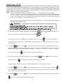
PRODUCT SPECIFICATIONS: PTC / PTH MODELS — ELECTRIC HEAT PERFORMANCE
3ULPDU\+HDWLQJIRU37&0RGHOV$X[LOLDU\+HDWLQJIRU37+0RGHOV6HHEHORZIRU3RZHU&RUG&RQÀJXUDWLRQ)
½ãÙ®
,ã;»tͿ
EÊ͘Ê¥
^ã¦Ý
230/208V
2.5
230/208V
230/208V
sʽã¦
133 units
EÊîĽ,ã®Ä¦;dhͬ«Ϳ
dÊã½
tããÝϲ
dÊã½
ÃÖÝ
D®Ä͘®Ùç®ã
ÃÖ®ãùϸ
MOP4
;ÃÖÝͿ
WÊóÙ
ÊÙ
ΛϮϯϬs
ΛϮϬϴs
ΛϮϲϱs
1
8,500
6,800
--
2,570 / 2,115
11.2 / 10.1
14.0
15
ϲͲϭϱW
3.5
1
12,000
9,900
--
3,570 / 2,935
15.5 / 14.1
19.4
20
ϲͲϮϬW
5
1
17,100
14,000
--
5,070 / 4,160
22.1 / 20.0
27.5
30
ϲͲϯϬW
265V
2.5
1
--
--
8,500
2,570
9.7
12.1
15
ϳͲϮϬW
265V
3.7
1
--
--
12,600
3,770
14.2
17.8
20
ϳͲϮϬW
265V
5
1
--
--
17,100
5,070
19.2
23.9
25
ϳͲϯϬW
ΎWd,ͬWdϬϵΎϱϬΎͬΎŚĂƐƚŚĞƐĂŵĞĂŝƌŇŽǁĂƐĂWdͬWd,ϭϮΎΎΎΎΎ;ŶŽƚĂǀĂŝůĂďůĞŽŶϳ͕ϬϬϬdhͬŚŵŽĚĞůƐͿ͘
PRODUCT SPECIFICATIONS: PTH MODELS — REVERSE-CYCLE HEATING PERFORMANCE
230/208 VOLTS
,ã®Ä¦Ö®ãùϷ
Voltage ¹, ³
BTU/h ϻ
Wd,
ϬϳϯΎΎyyy
Wd,
ϬϵϯΎΎyyy
Wd,
ϭϮϯΎΎyyy
Wd,
ϭϱϯΎΎyyy
230 / 208
230 / 208
230 / 208
230 / 208
6,800 / 6,800
8,300 / 8,100
10,900 / 10,500
13,500 / 13,300
Amps ¹²
3.5 / 3.5
4.1 / 4.1
5.6 / 5.6
7.0 / 7.0
tĂƩƐ ¹²
605 / 605
735 / 720
1040 /1020
1365 / 1345
KW5
3.3 / 3.3
3.3 / 3.3
3.1 / 3.1
2.9 / 2.9
310
310
310
360
Wd,
ϬϳϰΎΎyyy
Wd,
ϬϵϰΎΎyyy
Wd,
ϭϮϰΎΎyyy
Wd,
ϭϱϰΎΎyyy
CFM (Dry)
265/277 VOLTS
,ã®Ä¦Ö®ãùϷ
Voltage ¹, ³
BTU/h ϻ
265
265
265
265
6,800
8,200
11,000
13,500
Amps ¹²
3.0
3.6
4.8
6.0
tĂƩƐ ¹²
585
730
1040
1365
KW ϻ
3.4
3.3
3.1
2.9
CFM (Dry)
310
310
310
360
&23 &RHIÀFLHQF\RI3HUIRUPDQFHSHU$5,WHVWSURFHGXUHVXQLWVDUHUDWHGIRUFDSDFLWLHVDQGHIÀFLHQFLHV
See Notes on Page 7.
MC-DPTAC
www.amana-ptac.com
9
ACCESSORIES
CUSTOM COLOR SLEEVES
We offer over 150 different custom colors to choose from for your wall sleeves.
In addition, we can custom paint the exterior a different color from the interior
to meet your needs.
OUTDOOR GRILLES
Available in stamped-aluminum or architecturally louvered for application with
DQ$PDQDEUDQG:6'ZDOOVOHHYH
AGK—Extruded aluminum architectural grille available with anodized
DOXPLQXPÀQLVKDQGDEDNHGRQSDLQWÀQLVKIRUGXUDELOLW\&KRRVH
from 3 stock colors or a custom color to blend with your building’s
exterior color scheme.
CB (Clear Anodized),
'%'DUN%URZQ%URQ]H
TB (Stonewood Beige), WB (White), SB (Special/Custom Colors)
3*.³2QHSLHFHLQMHFWLRQPROGHGJULOOHXVLQJDSRO\PHUEOHQGRIHQJLneered thermoplastic high-impact strength material with chemical
resistance and an exterior UV protective coating.
Choose from 3 stock colors:
'%'DUN%URZQ%URQ]H7%6WRQHZRRG%HLJH:%:KLWH
CONDENSATE DRAIN KIT
Attaches to the wall sleeve base pan for controlled internal or external disposal
of condensate.
LOW-VOLTAGE WIRE HARNESS KIT
)RUTXLFNFRQQHFWLRQVRIWKHUHPRWHRUZLUHGWKHUPRVWDWVZLUHG(06RUIURQW
GHVNZLWKMXPSHUVDQGFRQQHFWRUV
REMOTE ESCUTCHEON KIT (NOT SHOWN)
Optional kit for use with units controlled via a wired, remote thermostat. Covers
control touch-pad for wired thermostat installations.
SUB-BASE KIT
The fully skirted sub-base conceals wiring while providing strong support, if
QHHGHG3OXJLQUHFHSWDFOHDQGÀHOGZLULQJDFFHVVVSHHGVLQVWDOODWLRQ(OHFWULFDO
accessories, such as fuse holders, circuit breakers and disconnect switches, meet
1(&UHTXLUHPHQWV
STANDARD DEPTH SLEEVES
WS900E
Standard PTAC sleeve
WS900SC
Seacoast triple protected
:6'
INTERNAL
Internal drain only for
window-wall installations
'.'VROGVHSDUDWHO\
161/16Η
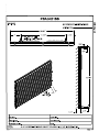
WALL SLEEVES
All our wall sleeves have industry standard dimensions of 42” wide x 16¹/16”
high. All Stonewood Beige G-90 metal wall sleeves are thermally insulated
DQG LQFOXGH D ZHDWKHU ERDUG IRU XVH GXULQJ FRQVWUXFWLRQ 7KH :6' 6&
and INTERNAL 14Я” depth is the industry standard. Sleeves may be shipped
separately to allow for installation during construction.
Η
ϰϮΗ
ϭϰЯ
EXTRA DEEP SLEEVES
We offer sleeves in several depths for thicker wall
LQVWDOODWLRQVRUVSHFLDOURRPFRQÀJXUDWLRQV
:6[['
16” to 24” in 1” increments
:6'
Extra deep 28”
:6'
Extra deep 30”
:6'
Extra deep 36”
STANDARD OUTDOOR GRILLE
SGK01B
SGK01TB
Single Pack
Stonewood Beige
^'<
ARCHITECTURAL OUTDOOR GRILLE
AGK01CB
$*.'%
AGK01TB
AGK01WB
AGK01SB
3*.'%
PGK01TB
PGK01TB
Anodized Aluminum (Silver)
'DUN%URQ]H%URZQ
Stonewood Beige
Amana White
Custom Colors
'DUN%URQ]H%URZQ
Stonewood Beige
Amana White
'<
or
W'<
<ϵϬϬϭ
ŽŶĚĞŶƐĂƚĞƌĂŝŶ<ŝƚ
(use with WS900E)
ŽŶĚĞŶƐĂƚĞƌĂŝŶ<ŝƚ;ƵƐĞǁŝƚŚt^ϵϬϬͿ
Wt,<Ϭϭ
tŝƌĞ,ĂƌŶĞƐƐ<ŝƚ
Z<ϭϬ
ZĞŵŽƚĞƐĐƵƚĐŚĞŽŶ<ŝƚ;ϭϬͲƉĂĐŬͿ
<ϵϬϬ
Wd^ϯϮϬ
Wd^ϯϯϬ
Wd^ϰϮϬ
Wd^ϰϯϬ
Wd^ϬϬϬ
<ϵϬϬ
Each kit contains 80 wires and wire nuts, enough to
attach a thermostat and one additional accessory
to 10 PTAC units. Wires come in assorted colors for
easy attachment.
230/208V 15/20A
230/208V 30A
265V 15/20A
265V 25A
Non-electrical
Optional
Fuse Holder
Location
Optional
Power Switch and Circuit Breaker
Location
Power Receptacle
Skirting
Skirting
Leveling Legs
Subbase Box Assembly
LEVELING LEGS
Gives wall sleeve front support and helps to level the unit for installation.
LL2B
>ĞǀĞůŝŶŐůĞŐƐĨŽƌ
t^ϵΎΎƐůĞĞǀĞƐ
HARD-WIRE KITS
Used to permanently wire to the chassis when a standard sub-base and power
cord are not used.
WdWt,t<ϰ
ƌŵŽƌĞĚĂďůĞͲĂůůǀŽůƚĂŐĞƐ
WdYKϯ
YƵŝĐŬŽŶŶĞĐƚͲϮϯϬͬϮϬϴs
WdYϬϰ
YƵŝĐŬŽŶŶĞĐƚͲϮϲϱΘϭϭϱs
10
www.amana-ptac.com
MC-DPTAC
ACCESSORIES (CONT.)
POWER DISCONNECT SWITCH
The PSHW**A power disconnect switch can be used for 265-volt or 230/208-volt
SK\VLFDOGLVFRQQHFWZKHUHUHTXLUHGE\ORFDOFRGHV7KHVZLWFKLVUDWHGDW
amp capacity. The switch is for use with and Amana® brand standard sub-bases
or PTPWHWK4 Hard Wire Kit.
FUSE HOLDER KIT
Cartridge-style fuses can be installed in the fuse holder for use in the sub-base or
chassis. Available in 15, 20 and 30 amp (included on 265-volt unit).
CIRCUIT BREAKER KIT (230/208V ONLY)
The circuit breaker kit, available in 15, 20 or 30 amp, can be used with Amana
brand sub-bases. It gives overcurrent protection, and its location allows you to
turn the unit on or off without tools.
W^,tϬϯ
230/208V
W^,tϬϰ
265V
&,<ϯϭϱ
FHK315E
230/208V 15A
&,<ϯϮϬ
FHK320E
230/208V 20A
230/208V 20A (R-410A)
&,<ϯϯϬ
FHK330E
230/208V 30A
<ϯΎΎ
ŝƌĐƵŝƚƌĞĂŬĞƌ<ŝƚ
230/208V 15A (R-410A)
230/208V 30A (R-410A)
DUCT EXTENSION KIT
([WHQGVDLUGLVWULEXWLRQWRDQDGMRLQLQJURRP&RQVLVWVRIDPDLQGXFWIRUWKHURRP
RIRULJLQDQGDQH[WHQVLRQGXFWWRUHDFKWKHDGMRLQLQJURRPDQGWHUPLQDOGXFW
37'.$DOORZVIRUWKHQHZ´%µVHULHVXQLWWRZRUNZLWKWKH´$µVHULHVGXFWNLWV
DĂŝŶƵĐƚ<ŝƚ
TRANSITION
džƚĞŶƐŝŽŶƵĐƚ<ŝƚ
BAFFLES
dĞƌŵŝŶĂůƵĐƚ<ŝƚ
D<ϬϮ
Main Duct – R-22
d<ϬϮ
Terminal Duct
D<Ϭϭ
Main Duct – R-410A
Wd<Ϭϭ
dƌĂŶƐŝƟŽŶƵĐƚKŶůLJʹZͲϮϮ
<ϬϮ
Extension Duct
Wd<Ϭϭ
dƌĂŶƐŝƟŽŶƵĐƚKŶůLJʹZͲϰϭϬ
POWER VENT KIT
Installation of Power Vent increases CFM up to approximately 95. Vent door will
automatically close when unit fan is off.
CONDENSER BAFFLE KIT
)RU XVH RQ QRQEDIÁHG JULOOHV 7KHVH GHÁHFWRUV GLUHFW WKH DLU LQ WRZDUG WKH
center and away from the inlet to prevent recirculation of the hot condenser air.
Ws<ϯ
230/208V – R-22
Ws<ϰ
265V – R-22
Ws<ϯ
230/208V – R-410A
Ws<ϰ
265V – R-410A
'<ϭ
ŽŶĚĞŶƐĞƌĂŋĞ<ŝƚ
Condenser Baffles
Condenser
Basepan
SUB-BASE EXTENSION COVER KIT
Converts older 30-amp sub-bases to allow for installation of the larger 30-amp
/&',SRZHUFRUGDQGSOXJV
CONDENSATE REMOVAL PUMP
&DQEHÀHOGLQVWDOOHG$VVLVWVLQUHPRYLQJFRQGHQVDWHGHYHORSHGE\KHDWSXPS
operation and transfers it to indoor coil to dissipate into room while adding
humidity to the room.
MC-DPTAC
SBEC10A
ϭϬWĂĐŬ
WϯϬϮ
230/208V – R-22
WϰϬϮ
265V – R-22
WϯϬϮ
230/208V – R-410A
www.amana-ptac.com
11
ACCESSORIES (CONT.)
SECURITY KEY LOCKS
,QFRQMXQFWLRQZLWKWKHWDPSHUUHVLVWDQWIURQWWKHLQVWDOODWLRQRI$PDQDEUDQG
security key locks prevents tampering of the controls used to set temperature,
heating and cooling functions. UL approved for institutional use only.
POWER DOOR KIT
Vent door will automatically open when unit fan is on.
THERMOSTATS
The following thermostats offer remote control. Any thermostat other than
those listed must be submitted to Goodman Company, L.P., for approval prior
to use.
HYDRONIC HEAT KIT
$GGRQ NLWV ÀW DOO XQLWV DOORZLQJ WKH DGGLWLRQ RI K\GURQLF ZDWHU RU K\GURQLF
steam heat to cooling and heating units. The kits feature left- or right-hand
piping. Unit retains complete service access with a kit installed. Unit must be
connected to and operated by a wall thermostat.
,t<Ϭϯ
,LJĚƌŽŶŝĐtĂƚĞƌ<ŝƚʹZͲϮϮ
,s<Ϭϯ
,LJĚƌŽŶŝĐ^ƚĞĂŵ<ŝƚʹZͲϮϮ
,t<Ϭϯ
,LJĚƌŽŶŝĐtĂƚĞƌ<ŝƚʹZͲϰϭϬ
,s<Ϭϯ
,LJĚƌŽŶŝĐ^ƚĞĂŵ<ŝƚʹZͲϰϭϬ
HYDRONIC VALVES
Water and steam valves are available for use with the HWK03 (water) and HVK03
(steam) heat kits.
<>Ϭϯ
^ĞĐƵƌŝƚLJ<ĞLJ>ŽĐŬ;ZͲϮϮͿ
<>Ϭϯ
^ĞĐƵƌŝƚLJ<ĞLJ>ŽĐŬ;ZͲϰϭϬͿ
W<ϯ
230/208V – R-22
W<ϰ
265V – R-22
W<ϯ
230/208V – R-410A
W<ϰ
265V – R-410A
Dʽ
,ã
^ã¦Ý
Êʽ
^ã¦Ý
®ÝÖ½ù
C5200609
D9945801
1246005/6
1246001
1246003
1246004
1241501
ϭΎ
ϮΎΎ
ϭΎ
ϭΎ
ϮΎΎ
ϮΎΎ
ϮΎΎ
1
1
1
1
1
1
1
Mech.
Mech.
Mech.
Digital
Digital
Digital
Digital
dùÖ
Manual
Manual
Manual
Manual
Manual
WƌŽŐƌĂŵ
Auto Change
^«ÖΙ
KÙ®Äãã®ÊÄ
ZŽƵŶĚ
ZĞĐƚͬ͘,Žƌŝnj͘
Rect./V or H
ZĞĐƚͬ͘,Žƌŝnj͘
ZĞĐƚͬ͘,Žƌŝnj͘
ZĞĐƚͬ͘,Žƌŝnj͘
Rect./Vert.
,LJĚƌŽŶŝĐ,ĞĂƚ<ŝƚͲdŽƉsŝĞǁ
,LJĚƌŽŶŝĐ,ĞĂƚ<ŝƚͲ^ŝĚĞsŝĞǁ
,LJĚƌŽŶŝĐ,ĞĂƚ<ŝƚͲZŝŐŚƚsŝĞǁ
s^ϮtEΎ
2-way/24V/NC/Steam
s^ϮtEKΎ
ϮͲǁĂLJͬϮϰsͬEKͬ^ƚĞĂŵ
stϮtEΎ
ϮͲǁĂLJͬϮϰsͬEͬŶĚ^ǁŝƚĐŚ
stϮtEKΎ
ϮͲǁĂLJͬϮϰsͬEKͬŶĚ^ǁŝƚĐŚ
stϯtEϮΎ
ϯͲǁĂLJͬϮϰsͬEͬEKͬŶĚ^ǁŝƚĐŚ
ΎWŽƉͲƚŽƉĐƚƵĂƚŽƌ
WIRELESS RF (RADIO FREQUENCY) CONTROLS
$OO'LJL6PDUW37$&VFRPHIDFWRU\UHDG\WREHFRQWUROOHGYLDZLUHOHVV5)GHYLFHV
2.4 Ghz 802 15.4 protocol assures robust communications and response.
12
DS01E
dŚĞƌŵŽƐƚĂƚ͗ϮͲǁĂLJĐŽŵŵƵŶŝĐĂƟŽŶƐ
DD01E
KĐĐƵƉĂŶĐLJ^ĞŶƐŽƌ͗D^ĂĐƟǀĂƟŽŶ
DT01A
Antennae / Router
GT01A
'ĞŶĞƌŝĐZĂĚŝŽŶƚĞŶŶĂͬZŽƵƚĞƌ
DD01F
ŽŽƌ^ǁŝƚĐŚ͗D^ĐƟǀĂƟŽŶ
WϬϭ
tĞďͲĞŶĂďůĞĚWůĂƞŽƌŵ^ĞƌǀĞƌ
DL01E
tĞďͲĞŶĂďůĞĚWůĂƞŽƌŵ^ĞƌǀĞƌ>ŝŶŬ
www.amana-ptac.com
MC-DPTAC
ACCESSORIES (CONT.)
REMOTE TEMPERATURE SENSOR
Unit can be wired to sense room temperature away from the PTAC to have
accurate readings.
RTS03
WIRED ENERGY MANAGEMENT CONTROL
,QFOXGHV 3,5 RFFXSDQF\ VHQVRU SRZHU IURP WKH 'LJL6PDUW FRQWURO DQG GRRU
VZLWFKFDQQRWEHXVHGZLWKDUHPRWHZLUHGWKHUPRVWDW
WEMR01W
ZĞĐĞƐƐͲŵŽƵŶƚĞĚĚŽŽƌƐǁŝƚĐŚ
WEMS01B
^ƵƌĨĂĐĞͲŵŽƵŶƚĞĚĚŽŽƌƐǁŝƚĐŚ;ƌŽǁŶͿ
WEMS01W
^ƵƌĨĂĐĞͲŵŽƵŶƚĞĚĚŽŽƌƐǁŝƚĐŚ;tŚŝƚĞͿ
SECM10001A
ůŝŵĂƚĞDĂƐƚĞƌϭϮЪ͟^ůĞĞǀĞ
džƚĞŶƐŝŽŶ;ϭϬWĂĐŬͿ
SEZA0501A
ŽŶĞŝƌĞϭϭЪ͟^ůĞĞǀĞ
džƚĞŶƐŝŽŶ;ϱWĂĐŬͿ
WdϭϬ
ϭϬWĂĐŬĨŽƌZͲϮϮƵŶŝƚƐ
WdϭϬ
ϭϬWĂĐŬĨŽƌZͲϰϭϬƵŶŝƚƐ
WALL SLEEVE EXTENSION ADAPTER KITS
Room-side extension kits to increase the depth of the existing sleeve to allow for
an industry-standard PTAC to be installed.
CURTAIN BAFFLE KIT
7KHFRORUPDWFKHGSRO\PHUFXUWDLQEDIÁHVKHOSWRSUHYHQWFXUWDLQVIURPIDOOLQJ
LQWR WKH GLVFKDUJH DLU VWUHDP DQG FDXVLQJ UHFLUFXODWLRQ UHGXFLQJ HIÀFLHQFLHV
and shortening compressor life.
ZĞŵŽƚĞǁĂůůͲŵŽƵŶƚĞĚƐĞŶƐŽƌ
MONTHLY MAINTENANCE
INTAKE AIR FILTERS
,WLVH[WUHPHO\LPSRUWDQWWRFOHDQWKHLQOHWDLUÀOWHUV RQFHD PRQWKRU PRUH RIWHQLI RSHUDWHG LQGXVW\RU GLUW\ ORFDWLRQVRU
FRQGLWLRQVWRSURSHUO\PDLQWDLQWKHRSHUDWLRQDOSHUIRUPDQFHRIWKH37$&XQLW7KHWZRLQWDNHDLUÀOWHUVFRQVWUXFWHGRIGXUDEOH
SRO\SURS\OHQHFDQEHHDVLO\LQVHUWHGLQWRWKHFDELQHWIURQWXVLQJWKHFDELQHWÀOWHUJXLGHV%HIRUHFOHDQLQJWKHLQWDNHÀOWHUVWXUQ
WKHXQLWRIIE\VHWWLQJWKHPRGHVZLWFKWRWKH2))SRVLWLRQ)LOWHUVVKRXOGEHFOHDQHGDVUHTXLUHG7KHIROORZLQJSURFHGXUHLVXVHG
WRUHPRYHWKHLQWDNHÀOWHUV
)DFLQJWKHXQLWSXOOXSRQWKHÀOWHUKDQGOHVORFDWHGDWWKHIURQWWRSRIWKHXQLW
3XOOHDFKÀOWHUXSZDUGDQGUHPRYH
&OHDQÀOWHUVZLWKYDFXXPRUZLWKUXQQLQJZDWHU5HYHUVHWKLVSURFHGXUHWRUHLQVWDOOWKHÀOWHUV
1RWH $FFHVVRU\ÀOWHUNLWVDUHDYDLODEOHIURP\RXUVDOHVSHUVRQ$OOÀOWHUVDUHSHUPDQHQWDQGFOHDQDEOH&RQVXOW\RXU
I&O Manual for other monthly cleaning instructions.
SPARE
P FILTERS
Helps keep dirt and lint out of the air and off the coil,
WKXV LQFUHDVLQJ WKH XQLW
V HIÀFLHQF\ $PDQD EUDQG
ÀOWHUVDUHHDV\WRUHPRYHZDVKDQGUHSODFH
&<ϭϬ
ϭϬͲÖ»Ͳ^Ù®Ý
&<ϭϬ
ϭϬͲÖ»Ͳ͕Ι^Ù®Ý
&<ϭϬ
ϭϬͲÖ»Ͳ^Ù®Ý;d«®Ý
ÃʽÙØç®ÙÝϮ¥®½ãÙÝ
Ö٫Ħ͘Ϳ
&<ϭϬ
ϭϬͲÖ»Ͳ^Ù®Ý;ZͲϮϮͿ
&<ϭϬ
ϭϬͲÖ»Ͳ͕Ι^Ù®Ý;ZͲϮϮͿ
REPLACEMENT CHARCOAL FILTER KIT
Absorbs airborne odors caused by cigarette, pipe
or cigar smoke and odors caused by mold, mildew,
HWF )LOWHUV DUH PDGH RI SRO\HVWHU ÀEHUV FRDWHG ZLWK
activated charcoal and are individually wrapped. These
ÀOWHUV DUH SHUPDQHQW DQG FDQ EH ZDVKHG RU FOHDQHG
Call your Amana® brand PTAC sales person for details.
ÀOWHUVSHUSDFN
MC-DPTAC
www.amana-ptac.com
13
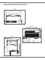
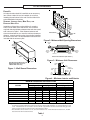
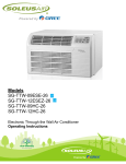
UNIT WITH ACCESSORY WALL SLEEVE AND SUB-BASE ACCESSORY
TOP VIEW
42"
40"
6 - 1 / 8"
24 - 5 / 16"
1"
9 - 9 / 16"
Location of external drain holes
on bottom flange of Wall Sleeve
Air
Flow
Air
Flow
Air
Flow
Control
Door
Air Discharge Grille
3
1"
3" Clearance
to side walls
"
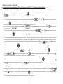
FRONT VIEW
58” LCDI CORD SET — 230V/208V UNIT*
42"
LEFT
R I GHT
16-1/16"
2-5/8"
RIGHT VIEW
AIR DISCHARGE GRILLE IS
REVERSIBLE TO PROVIDE EITHER
15° OR 40° DISCHARGE ANGLE
7/8"
STAMPED GRIL
3-1/4"
MIN
21-1/2"
2"
MAX
1-3/8"
ARCH GRILLE
14-1/8"
WALL SLEEVE
7-3/8"
1" AND 3/4" CONCENTRIC KNOCKOUTS BACK
& BOTTOM OF SUBBASE (ELECTRICAL ONLY)
58" CORD
SET 230V/208V UNIT*
18" CORD
SET 265V UNIT*
15°
40°
16-1/16"
HINGED
CONTROL
DOOR
OPTIONAL
SUBBASE
4"
13/16"
1 -3
11-3/8"
13/16"
14
1
C
DR
www.amana-ptac.com
MC-DPTAC
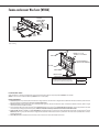
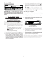
FRAMING FOR ACCESSORY WALL SLEEVE (WS9XX)
Alternative
Fastening Method
(Field Supplied)
Wood Screw
Toggle Bolt
Expansion
Anchor Bolt
Mounting
Holes
(Drilled by
Installer)
Plastic
Anchor
Screws
tĂůů^ůĞĞǀĞŵƵƐƚĞdžƚĞŶĚĂŵŝŶŝŵƵŵŽĨЬ͟ďĞLJŽŶĚŽƵƚƐŝĚĞǁĂůůƚŽĂůůŽǁĨŽƌ
ƉƌŽƉĞƌĐĂƵůŬŝŶŐ͘
JACK STUDS
HEADER - 4" x 4" OR
DOUBLE 2"x 4" ON EDGE
MAIN STUD
16 1/4"
MIN
42
1/4
"
ADJUST FRAMING TO
SECURE THIS DIMENSION
JACK STUD
CRIPPLE
FINISHED FLOOR
SUB-FLOOR
tĂůůƐůĞĞǀĞŽƉĞŶŝŶŐŚĞŝŐŚƚƐŚŽƵůĚďĞ
ƐƋƵĂƌĞĚǁŝƚŚǁĂůůƐůĞĞǀĞŽƉĞŶŝŶŐǁŝĚƚŚ͘
,сϭϲЬΗ
tсϰϮЬΗ
&ÝãĮĦt½½^½ò
tŚĞŶŝŶƐƚĂůůĞĚŝŶĂŶŽƉĞŶŝŶŐ͕ƚŚĞtĂůů^ůĞĞǀĞŵƵƐƚďĞŚŽƌŝnjŽŶƚĂůůLJůĞǀĞů;ƐŝĚĞͲƚŽͲƐŝĚĞͿĂŶĚƉŝƚĐŚĞĚЬďƵďďůĞƚŽƚŚĞŽƵƚƐŝĚĞ͘
(EKd͗dŽĞŶƐƵƌĞƵŶŝƚ͛ƐŵĂdžŝŵƵŵĞĸĐŝĞŶĐLJ͕KEKdŽǀĞƌͲŽƌƵŶĚĞƌͲƉŝƚĐŚ͘Ϳ
/ÄÝã½½ã®ÊÄEÊãÝ
ϭ͘ /Ĩ^ƵďͲďĂƐĞ;Wd^ΎΎΎͿŝƐŝŶƐƚĂůůĞĚ͕ĂůůŽǁŵŝŶŝŵƵŵϯЬ͟ŚĞŝŐŚƚĐůĞĂƌĂŶĐĞĂŶĚŵĂdžŝŵƵŵϱ͟ŚĞŝŐŚƚĐůĞĂƌĂŶĐĞďĞƚǁĞĞŶǁĂůůƐůĞĞǀĞĂŶĚŇŽŽƌ͖ĂůůŽǁŵŝŶŝŵƵŵ
Ϯв͟ƉƌŽƚƌƵƐŝŽŶĨƌŽŵĂĮŶŝƐŚĞĚǁĂůů͘See Note 4 if using hydronic units.
2. ƌĂŝŶ<ŝƚ;<ϵϬϬͿƐŚŝƉƉĞĚƐĞƉĂƌĂƚĞůLJ͘ĂŶďĞŵŽƵŶƚĞĚĞŝƚŚĞƌƌŝŐŚƚƐŝĚĞ͕ůĞŌƐŝĚĞŽƌďŽƩŽŵŽĨƐůĞĞǀĞ͘/ĨŵŽƵŶƚĞĚƚŽďŽƩŽŵŽĨƐůĞĞǀĞ͕ĂůůŽǁϮ͟ŚĞŝŐŚƚ
ĐůĞĂƌĂŶĐĞĨƌŽŵŇŽŽƌƚŽďŽƩŽŵŽĨƐůĞĞǀĞ͘
ϯ͘ &Žƌh>ĂƉƉƌŽǀĂů͕ϮϲϱsƵŶŝƚƐŵƵƐƚƵƐĞŵĂŶĂ®ďƌĂŶĚ^ƵďͲďĂƐĞ;Wd^ΎΎΎͿŽƌŵĂŶĂ®ďƌĂŶĚ,ĂƌĚtŝƌĞ<ŝƚ;WdWt,t<ϰͿ͘KǀĞƌĐƵƌƌĞŶƚƉƌŽƚĞĐƟŽŶŽŶϮϲϱs
ƵŶŝƚƐŵƵƐƚďĞďLJĐĂƌƚƌŝĚŐĞͲƐƚLJůĞƟŵĞĚĞůĂLJĨƵƐĞƐ͕ǁŚŝĐŚĂƌĞŝŶĐůƵĚĞĚĂŶĚĨĂĐƚŽƌLJͲŝŶƐƚĂůůĞĚŽŶƚŚĞŵĂŶĂ®ďƌĂŶĚϮϲϱsĐŚĂƐƐŝƐ͘
ϰ͘ /Ĩ,LJĚƌŽŶŝĐ<ŝƚ;,t<ϬϯŽƌ,s<ϬϯͿŝƐŝŶƐƚĂůůĞĚ͕tĂůů^ůĞĞǀĞŵƵƐƚĞdžƚĞŶĚĞdžĂĐƚůLJϯΗŝŶƚŽƚŚĞƌŽŽŵĨƌŽŵƚŚĞĮŶŝƐŚĞĚŝŶƚĞƌŝŽƌǁĂůů͘/ĨƵƐŝŶŐƚŚĞŵĂŶĂ®ďƌĂŶĚ
^ƵďͲďĂƐĞ;Wd^ΎΎΎͿ͕ŽŶůLJƚŚĞŵŝŶŝŵƵŵϯЬ͟ŚĞŝŐŚƚĐůĞĂƌĂŶĐĞďĞƚǁĞĞŶǁĂůůƐůĞĞǀĞĂŶĚŇŽŽƌŝƐƉĞƌŵŝƐƐŝďůĞ͘hŶŝƚŵƵƐƚĂůƐŽďĞŽƉĞƌĂƚĞĚǁŝƚŚĂƌĞŵŽƚĞͲ
ŵŽƵŶƚĞĚƚŚĞƌŵŽƐƚĂƚ͘
5. /ĨƵĐƚ<ŝƚ;D<ϬϮͿŝƐŝŶƐƚĂůůĞĚ͕ĂůůŽǁĂŵŝŶŝŵƵŵŽĨϮд͟ŝŶƚŽƚŚĞƌŽŽŵĨƌŽŵƚŚĞĮŶŝƐŚĞĚŝŶƚĞƌŝŽƌǁĂůů͘
MC-DPTAC
www.amana-ptac.com
15
PACKAGED TERMINAL AIR CONDITIONERS
AND HEAT PUMPS
WITH
CONTROL BOARD
%XWWRQ &RQWURO 3DG
One-Touch Activation
Total Fan Control
(DV\WR5HDG'LVSOD\
First-Year Warranty: Parts & Labor on entire unit
Second through Fifth Year: Parts & Labor on certain sealed system components
Second through Fifth Year: on certain functional parts only
p
* Complete warranty details available at www.amana-ptac.com.
Amana® is a trademark of Maytag Corporation or its related companies and used under license to Goodman Company, L.P. All rights reserved. Our continuing commitPHQWWRTXDOLW\SURGXFWVPD\PHDQDFKDQJHLQVSHFLÀFDWLRQVZLWKRXWQRWLFH*RRGPDQ&RPSDQ\/3+RXVWRQ7H[DV3ULQWHGLQWKH86$
16
www.amana-ptac.com
MC-DPTAC
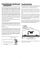
PTAC WALL SLEEVE
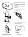
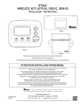
INSTALLATION INSTRUCTIONS
The wall sleeve must be installed before the air conditioner or heat pump chassis can be
set in place. Read the instructions thoroughly before proceeding.
When 230/208 volt units are to be installed, the power
supply may be either cord connected or permanent
wiring. Permanent wiring may be done through the hard
wire junction box, or the accessory subbase.
When 265 volt units are to be installed, the power supply
must be permanent wiring. Permanent wiring may be
done through the accessory hard wire junction box, or
the accessory subbase. An exposed cord connection
on 265 volt units is not permitted.
The subbase accessory includes leveling legs. If added
wall sleeve support is required and the subbase is not to
be used an accessory leveling leg kit may be installed.
Made in USA
Contents
KIT ACCESSORIES ..................................................................................................... 2
DRAIN KIT ....................................................................................................... 2
SUBBASE, LEVELING LEGS, MAIN DUCT, AND HYDRONIC HEAT KITS ........................ 2
PRE-INSTALLATION CONSIDERATIONS .................................................................. 3
OUTDOOR ENCLOSURE PANEL REMOVAL .............................................................. 3
WALL SLEEVE INSTALLATION .................................................................................. 4
RECOGNIZE THIS SYMBOL AS A SAFETY PRECAUTION
ATTENTION INSTALLING PERSONNEL
As a professional installer you have an obligation to know the product better than the customer. This
includes all safety precautions and related items.
Prior to actual installation, thoroughly familiarize yourself with this Instruction Manual. Pay special
attention to all safety warnings. Often during installation or repair it is possible to place yourself in a
position which is more hazardous than when the unit is in operation.
Remember, it is your responsibility to install the product safely and to know it well enough to be able to
instruct a customer in its safe use.
Safety is a matter of common sense...a matter of thinking before acting. Most dealers have a list of
specific good safety practices...follow them.
The precautions listed in this Installation Manual are intended as supplemental to existing practices.
However, if there is a direct conflict between existing practices and the content of this manual, the
precautions listed here take precedence.
Part No. A3495105
Printed in USA
August 2005
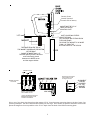
KIT ACCESSORIES
DRAIN KIT
An indoor/outdoor drain kit is available as an accessory
item. When a drain kit is to be installed, do so before
installing the wall sleeve in the wall. See the drain kit for
actual installation instructions.
4
10 2 1 /
Mi 75 m 4"
nim m
um
SUBBASE, LEVELING LEGS, MAIN DUCT, AND
HYDRONIC HEAT KITS
16 1/4"
415 mm
Minimum
Installation of these kits requires drilling of mounting
holes on both sides of the wall sleeve. The minimum
required clearance distance between the wall sleeve and
wall is shown in Table 1. If the distance between wall
sleeve and wall will be at or near the minimum clearance
distance, mount these kits on the sleeve before installing
the sleeve in the wall. The kit installation instructions are
included with the accessory kits.
Finished Floor
Dimension "B"
in Table 1
Figure 2 - Minimum Wall Opening Dimensions
Outside
Wall
16 1/16"
410 mm
Top of Wall Sleeve
Internal
Adjacent
Wall
42"
1065 mm
"A"
Minimum
"A"
Minimum
Internal
Adjacent
Wall
Allow Front Clearance (See Table 1)
14 1/8"
359 mm
Figure 3 - Minimum Unit Clearances
Wall Receptacle Within 58" From
Bottom Right Side Corner on
208/230 VAC Units Only
Outside
Wall
Figure 1 - Wall Sleeve Dimensions
Cabinet
Side
Room
Side
"C" in
Table 1
Carpet or
Finished Floor
"B" in
Table 1
1/4"
6 mm
Minimum
Figure 4 - Minimum Interior and Exterior
MINIMUM CLEARANCES AND PROJECTIONS
OPTION
Wall Sleeve Only
Subbase Kit
Leveling Legs Kit
Duct Kit
Hydronic Heat Kit "A Series"
Hydronic Heat Kit "J Series"
Drain Kit
Hardwire Kit
1
2
3
MINIMUM CLEARANCES
A (Figure 2)
B (Figure 3)
Inches
mm
Inches
mm
3
75
0
0
3
75
3 1/4
85
3
75
3
75
3
75
0
0
3
3
0 to 3 1/4 0 to 85
9
230
6
150
0
0
1
1
'0
'0
3
75
3
75
1 1/4
30
MINIMUM PROJECTION
C (Figure 4)
Inches
mm
0
0
2 3/4
70
2
50
2 3/8
35
2
2
3
75
2 1/2
65
0
0
0
0
If inside mounted then B = 1 1/2 inches (40 mm)
To achieve a flush fit between the hydronic front and the finished wall, Dimension “C” must be between 3” and
3 1/8”. If this dimension is more than 3 1/8” there will be a gap between the front and the wall. This gap could
permit occupant access to hydronic lines or other dangerous parts.
This dimension can be from 0” to 3-1/4”, but cannot exceed 3-1/4”. If this dimension exceeds 3-1/4”, the skirt
around the front will not reach the floor.
Table 1
2
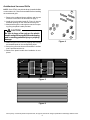
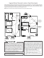
PRE-INSTALLATION CONSIDERATIONS
Before proceeding with the sleeve installation, ensure the following guidelines for locating the wall opening and sleeve
are met:
•
•
•
•
•
•
•
•
The wall opening must be the correct size. See
Figure 1 for wall sleeve dimensions and Figure 2
for minimum wall opening size.
The wall sleeve will need to be installed with
minimum clearances to the floor and adjacent
walls. Minimum projections of the sleeve into and
out of the room will also have to be met. See
Figures 3 and 4 as well as Table 1 for details.
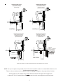
If installed in a concrete or masonry wall, a lintel
must be provided in the wall opening for support.
Do not use the wall sleeve as a lintel. See
Figure 5 for a typical lintel construction.
When installed in the opening, the wall sleeve
must be horizontally level from side to side and
pitched (one quarter bubble in the sight glass) to
the outside. DO NOT SLOPE THE WALL SLEEVE
TOWARD THE ROOM. (Figure 5)
The installer must determine and supply the
mounting bolts and/or screws to attach the wall
sleeve to the sides of the wall opening. Make sure
the wall opening is adequate for strong support.
The installer must provide adequate sealing and
insulation around the sleeve after it is installed.
See Figure 6 for one of many types of constructions.
If used, a 208/230-volt wall receptacle must be
located within 58 inches of the lower right sleeve
corner. Extension cords must not be used with the
unit. See the note on Figure 1.
For installations in walls deeper than 13-7/8
inches, special care is necessary to prevent
problems with rain water, condensate drainage
and intake/discharge air. Under these circumstances, careful job site analysis and precautions
are required. You must consult with your Sales
Representative and receive approval before
attempting such installations.
Wood
Frame
Lintel
Figure 5 - Framing with Lintel
Concrete
Lintel
13 1/2" (340 mm)
Maximum
(No Accessories)
13 3/4"
350 mm
1/4"
6 mm
Minimum
Projection
Steel
Lintel
Caulk Top,
Bottom, and
Both Sides
Power Supply
Conduit
Finished
Floor
Receptacle
Figure 6 - Block and Brick Veneer
Installation
Sleeve
Stiffener
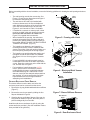
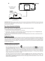
OUTDOOR ENCLOSURE PANEL REMOVAL
The sleeve stiffener must be taken out before the
enclosure panel can be removed from the sleeve.
1. Remove the zig-zag folded cardboard sleeve stiffener
(Figure 7).
Figure 7- Sleeve Stiffener Remova
2. Remove the rear closure panel by folding the four
flaps as indicated in Figure 8.
Rear Closure
Panel
3. Grasping the top and bottom flanges of the rear closure panel as shown in Figure 9, the entire panel is
pulled out diagonally from one side.
Install the wall sleeve condenser air grille by using the
screws and holes provided. (See the Installation Instructions provided for the grille kits.)
Flaps
Figure 8 - Rear Enclosure Panel
3
Figure 9 - Panel Removal
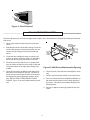
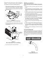
WALL SLEEVE INSTALLATION
After the wall opening is checked and approved for location, size, and clearances, complete the following to install the
wall sleeve.
1. Remove the outside enclosure panel from the wall
sleeve.
Alternative
Fastening Method
(Field Supplied)
2. Slide the wall sleeve into the wall opening. Do not distort the cabinet shape to fit the wall opening; the unit
chassis must fit snugly and uniformly into the wall
sleeve.
Wood Screw
Toggle Bolt
Expansion
Anchor Bolt
Mounting
Holes
(Drilled by
Installer)
3. Locate the sleeve within the range of minimum projections, as shown in Figures 3 and 4, so both sides
are at least the minimum projection from the wall.
Plastic
Anchor
4. Check the level of the wall sleeve. For proper drainage, the sleeve should be level from side to side and
one-quarter bubble in the sight glass sloping to the
outside.
Screws
Figure 10 - Wall Sleeve Attachment to Opening
5. Two holes will need to be drilled in both sides of the
wall sleeve for mounting into the wall. Drill holes of
proper size and in the proper location so the screws
will engage into strong supporting members of the
wall. DO NOT DRILL THROUGH BOTTOM OF
SLEEVE. Figure 10 shows possible fastening methods.
6. Check the level of the wall sleeve and adjust if necessary.
7. Caulk or seal around the outside of the entire sleeve.
8. If the unit chassis will not be installed immediately, replace the enclosure panel on the outside opening of
the sleeve. This will prevent weather damage to the
building interior.
9. Recycle or dispose of packaging materials per local
codes.
4
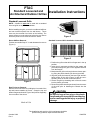
PTAC
Standard Louvered and
Architectural Outdoor Grilles
Installation Instructions
Standard Louvered Grille
NOTE: A baffle kit must not be used with a standard
louvered grille on any PTAC installation.
Before installing the grille, remove the cardboard stiffener
and rear enclosure panel from the wall sleeve. These
items can be removed from inside of the building. The
sleeve stiffener must be taken out before the rear sleeve
enclosure panel can be removed from the sleeve.
Sleeve Stiffiner Removal
Fold the two outside flaps “A” in and downward to remove
(Figure 1).
Figure 2
Standard Louvered Grille Installation Instructions
A
A
Figure 3
Figure 1
Rear Enclosure Removal
Remove the rear enclosure by folding the front ends of the
top and bottom towards the center. Grasp the top and
bottom flanges as shown in Figure 2 and pull out diagonally
from one side of the sleeve.
1. Position the grille so that all four flanges are in the up
position.
2. Insert the six grommets provided so the square end
protrudes through the grille in the opposite direction
from the flanges.
3. Manipulate the grille out through the rear sleeve opening using the plastic handle (not shown) provided.
4. Align the guide pins located in the lower right- and lefthand corners of the grille (Figure 3) with the corresponding holes in the rear of the wall sleeve.
5. Secure the grille by threading each of the six screws
into the plastic grommets.
6. Remove the plastic handle (not shown) from the center
of the grille prior to installing the chassis into the
sleeve.
CAUTION
Be sure to keep a firm grip on the plastic
handle and grille to prevent it from dropping
and /or causing possible injury or property
damage.
Made in USA
The installation and servicing of this equipment should be
performed by qualified, experienced technicians.
October 2000
Rev. 1
A3495703
Architectural Louvered Grille
NOTE: Some PTACs may include factory-installed baffles
on the outdoor coil. Remove these baffles before installing
the architectural grille.
B
1. Remove the cardboard sleeve stiffener and the rear
enclosure of the sleeve as described on page 1.
2. Install the four threaded studs (B, Figure 4) into the
threaded openings on the inside face of the grille.
3. Manipulate the grille out through the rear sleeve opening using the plastic handle provided.
CAUTION
Be sure to keep a firm grip on the plastic
handle and grille to prevent it from dropping
and /or causing possible injury or property
damage.
C
D
Figure 4
4. Attach the grille to the sleeve by aligning and inserting
the threaded studs in the corresponding holes.
5. Secure the grille to the sleeve with washers C and hex
nuts D provided with the kit.
6. Remove the plastic handle after installation is completed.
B
B
PLASTIC
HANDLE
B
B
Figure 5
Figure 6
Due to policy of continual product improvements, the right is reserved to change specifications and design without notice.
2
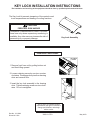
KEY LOCK INSTALLATION INSTRUCTIONS
The installation and servicing of the equipment should be done by qualified experienced technicians.
The Key Lock kit prevents tampering of the controls used
to set temperatures and heating or cooling functions.
CAUTION
PERSONAL RISK HAZARD
Underwriter’s Laboratories Inc. listed. For institutional use only where supervisory monitoring is
available. Any other use may increase the risk of
personal injury or property damage.
P1201702R
Key Lock Assembly
Installation Instructions
RETAINING
SCREW
1. Remove front from unit by pulling bottom out
and then lifting upward.
2. Loosen retaining screw by one-turn counterclockwise. Disengage door pins from housing
slots and remove door.
3. Insert the key lock assembly in the housing
slots. Tighten retaining screw one-turn clockwise. Do not overtighten.
Due to policy of continual product
improvement, the right is reserved to
change specifications and design
without notice.
Part No. 11113602
Printed in U.S.A.
Made in USA
May 2003
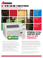
RAISING THE BAR IN PTAC CONTROLS
Designed exclusively for Amana PTAC units, DigiSmart technology has dramatically raised the bar
in PTAC controls. Your guests will appreciate its large, easy-to-read LED readout that allows them to check the temperature with a quick
glance and, if desired, to change the setting to a specific temperature by pressing a button. The ability to select a precise temperature
helps your guests avoid over-cooling their rooms, a situation that often occurs with knob-type controls, which are less precise.
What’s more, the DigiSmart Control Board offers many programmable features and self-diagnostics that help facility personnel better
manage the care and maintenance of the PTACs in their facility and allow management to better control operating costs. One of these
features is a “setback” program that senses whether or not a unit has been touched within a specific window of time. If the unit has not
been touched, the system then concludes that the room in which the PTAC is located is vacant and begins setting the temperature
back in three successive steps, thereby saving energy.
The most significant breakthrough in the PTAC industry, is our new DigiSmart Wireless Energy Management Suite that helps
ensure that you minimize energy used in cooling your guest rooms when your guests are not in the room.
ENHANCE ROOM VALUE, GAIN CONTROL AND START SAVING 35% ON PTAC ENERGY COSTS!*
There are three key pieces to the DigiSmart Wireless Energy Management Suite: a Wireless Antenna, a Remote-Mounted Thermostat,
and a combination Motion Sensor/Door Switch. When installed withan Amana brand PTAC, the system works as follows.
(1) Plug in the DigiSmart Antenna.
Once a technician plugs this small antenna into the
DigiSmart control board, the unit is ready to communicate
with the Thermostat and the Motion Sensor/Door Switch.
And as you install these amazing DigiSmart antennae
in all of the PTACs in your facility, they will form a network
and begin to talk to one another.
(1)
(2)
(2) Set and Mount the DigiSmart Remote-Mounted Thermostat.
Simply push a button inside the thermostat to link it to the PTAC
and mount the thermostat on the wall.
(3) Set and Mount the DigiSmart Occupancy Control.
(3)
A simple push of a button will link this device to the PTAC. Then just
mount the DigiSmart Motion Sensor/Door Switch above the door, and the Amana
brand’s proprietary software routines will begin working with this device to determine whether the room is occupied. While the guest is
in the room, the PTAC maintains the selected temperature. When the guest is away, however, the energy management system sets the
temperature back based on setback routines that you can determine yourself.
The new DigiSmart Wireless Energy Management Suite is an extremely valuable way for you to help control the energy
used in your guest rooms, which can dramatically reduce your operating costs over time.
Call us at
800-647-2982 for complete details.
© 2010 Goodman Company, L.P. · Fayetteville, Tennessee · www.amana-ptac.com.
·
CB-PTACRFA
*These savings represent savings over time as compared to the same PTAC model without the DigiSmart EMS System installed and were generated using general assumptions including energy
loads, local weather averages and use of occupancy controls. Actual savings will vary according to actual use habits, room square footage, and how the unit is installed.
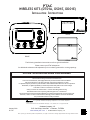
PTAC
WIRELESS KITS (DT01A, DS01E, DD01E)
INSTALLATION INSTRUCTIONS
AIR CONDITIONING SENSOR
DD01E
A
Heating & Air Conditioning
®
DS01E
DT01A
The following installation instructions are for a typical installation.
Please contact your PTAC salesperson
for additional assistance and explanation prior to ordering materials or cutting openings.
ATTENTION INSTALLING PERSONNEL
As a professional installer you have an obligation to know the product better than the customer.
This includes all safety precautions and related items.
Prior to actual installation, thoroughly familiarize yourself with this Instruction Manual.
Pay special attention to all safety warnings. Often during installation or repair
it is possible to place yourself in a position which is more hazardous than when the unit is in operation.
Remember, it is your responsibility to install the product safely and to know it well enough
to be able to instruct a customer in its safe use.
Safety is a matter of common sense...a matter of thinking before acting.
Most dealers have a list of specific good safety practices...follow them.
The precautions listed in this Installation Manual are intended as supplemental to existing practices.
However, if there is a direct conflict between existing practices and the content of this manual,
the precautions listed here take precedence.
®
is a registered trademark of Maytag Corporation or its related companies
and is used under license to Goodman Company, L.P., Houston, TX. All rights reserved.
January 2010
IO-729
Goodman Company, L.P.
5151 San Felipe, Suite 500 • Houston, TX 77056
www.amana-ptac.com • © 2009 Goodman Company, L.P.
Due to policy of continued product improvement, the right is reserved to change specifications and design without notice.
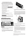
BEFORE BEGINNING INSTALLATION,
PLEASE READ IMPORTANT NOTES BELOW:
•
If devices are to be powered, field installed wiring will
need to be run from thermostat location to unit location
and from door sensor location to PTAC location and from
wired magnet to sensor location.
•
If wireless platform DP01, DP01E or DL01E are being
utilized, then room numbers MUST BE CONFIGURED in
the control board prior to binding wireless devices.
•
Front Mounting Screw
accessed
through louvers.
All units must have DT01A antenna for wireless devices
to communicate properly.
3. Remove cabinet front from chassis by tilting the bottom of the front forward, lifting slightly up and forward.
Sequence of installation:
•
1) Mount the peripherals
2) Verify operation of the door sensor
4. Mount the antenna as high up on the control panel as
possible and as far to the right as possible in a location
that will not interfere with the reinstallation of the PTAC
polymer room front. Mark holes for screw location. Remove antenna housing and drill two 1/8” holes where
marked. Some units may have the holes already predrilled in the correct location.
3) Program room numbers
4) Bind peripherals
5) Reattach peripherals to their mounted backplates
6) Install optional security screws
•
Installation and videos are available on our website at
www.amana-ptac.com.
•
Use only one DD01E Passive Infrared Motion Sensor (PIR)
door switch combination device and/or one DS01E to one
DigiSmart™ PTAC unit.
Antenna Installation For DT01* Kit
Wire
A DT01* antenna must be installed on the digital PTAC to
allow operation of either the DS01* remote RF thermostat
or a DD01* combination PIR motion sensor and door switch.
DT01* Mounting
5. Remove antenna cable and route cable through opening in bottom of antenna housing.
6. Mount antenna housing with two screws as shown in
figure. (NOTE: The Amana® brand logo should be in
the lower right hand corner).
Preparation
7. Plug wire harness from antenna into connector on the
control board to the right of the master switch, being
careful not to bend and/or break the wires when you
connect the cable to the PTAC. Gently push the connector into place by pushing on the edge of the connector with your thumb nails. Avoid pushing directly on
the wires.
1. Disconnect power to the unit by unplugging the power
cord at the wall outlet or subbase, or disconnect power
at the fuse box or circuit breaker.
2. If the cabinet front is screwed to the chassis, remove
the 1/4” screw (or screws) located behind the inlet grille.
Pull the inlet grille forward from the top of the grille to
access screw(s).
8. Restore power to the PTAC unit.
9. Reinstall the polymer room cover.
NOTE: The LED must be oriented at the top of the antenna
housing (the Amana® brand logo will be on the lower right)
for proper unit operation.
2
Mounting Sensor/Door Magnet Installation
for DD01E Kit
Thermostat Installation for DS01E Kit
NOTE: A DT01* must be installed on the digital PTAC unit
for the DS01* to be operable.
Skip these steps if not installing.
DDO1E must be mounted on the top door frame as close to
the door as possible in the horizontal position.
1. Select thermostat mounting location about five feet
above the floor, on an inside wall, out of direct sunlight, away from sources of radiant heat (lamps, fireplaces, heating and air conditioning equipment, etc.),
away from windows or door to the outside, and avoid
areas with poor air circulation. If the PIR in the thermostat is to be used with a DD01* device as a 2nd motion sensor, point the thermostat towards the area where
you are requiring additional motion sensing.
A DT01E must be installed in the PTAC unit for the DD01E to
be operable.
Skip these steps if not installing.
1. Remove motion sensor from mounting plate by pulling
apart.
2. Mount the back plate on the door trim directly above
the door using the enclosed screws. (Position so the UP
arrow is pointing up.) Mount the DD01E as low as possible on the door frame to be as close to the moving
part of the door as possible without interfering with
the door opening or closing. Choose a location for mounting the back plate that will provide good coverage of
the PIR for motion into the room. Make sure that the
DD01E will not interfere with the normal opening and
closing of the door.
Ensure location is out of the path of foot traffic where
a person might accidentally bump into the thermostats
and damage the device.
2. Remove thermostat from mounting plate by pulling apart
at the bottom of the thermostat about 1”, and slide
thermostat up to release from the top of the mounting
plate.
DO NOT SNAP MOTION SENSOR IN PLACE UNTIL AFTER
BINDING PROCESS.
3. Place thermostat mounting plate against the wall at desired location and mark placement of mounting holes.
Make sure the UP arrow is pointing up on the mounting
plate.
See Binding Instructions, page 9.
DD01*
4. If mounting in drywall, tap plastic anchors into wall. For
other surfaces, drill a 3/16” hole.
DOOR TRIM
5. Screw mounting plate to the wall. DO NOT SNAP THERMOSTAT INTO PLACE UNTIL AFTER BINDING PROCESS.
See Binding Instructions on page 9.
DOOR
(CENTER MAGNET WITH DD01*)
6. Install four (4) AA batteries (included) into the back of
the thermostat. Terminals are marked “+” and “-” for
polarity.
DD01E Mounting
NOTE: Do not install thermostat on wall plate until all configuration settings and binding processes have been completed.
3. Install two (2) AA batteries (included) into the back of
the thermostat. Terminals are marked “+” and “-” for
polarity. Do NOT put batteries into the device until
AFTER the magnet location is selected to test.
WIRED POWER OPTION
1. If the option for wired power is used, the two thermostat wires (20 gauge minimum field supplied) can be
connected to the thermostat.
2. Route wires through the opening in the mounting plate.
3. Loosen set screws on wired terminal and insert wires
into the opening. Tighten set screws.
4. Connect wires at PTAC unit to terminal pins C and R.
The wire harness kit PWHK01C is required for this connection.
3
Door Magnet Installation
WIRED MAGNET AND POWERED DOOR
SENSOR OPTION
NOTE: Magnet buckets are shipped from the factory with
the magnets in position A. The position may change based
on the door and door frame alignment on page 5.
In cases where there is no top door frame, the sensor will
need to be mounted on the wall next to the door. In these
cases a wired magnet (a field supplied single pole single
throw wired magnet) can be recessed or surface mounted
and wired to the door sensor. The magnet will be a recessed
style magnet with wired switch. The wires for the sensor (20
gauge field supplied) in the magnet will need to be run
during construction. Two wires will be run from the door
sensor location to the PTAC unit; the remaining two wires
will be run from the magnet location to the sensor location.
The door sensor has four (4) terminal locations for wired
power and/or wired magnets. The two (2) terminals closest
to the binding button are for wired power and the top two
(2) terminals are for wired magnet.
Mount the door magnet holder on the front of the door
where it will be as close as possible to the bottom of the
motion sensor but no more then 1/8" from the bottom
center of the motion sensor (DD01E) when the door is
closed.
Select the correct slot in the magnet holder (there are
three slots) to obtain 15/16" from back of sensor mounting
plate to the center of the magnet. (If you can easily slide
a business card between the magnet and the DD01E sensor,
unit is properly placed vertically.) See image below for
magnet and sensor alignment.
Run the magnet wires through the opening in the center of
the door sensor wall plate.
Screw in place with the 2 screws provided. Open and close
the door to make sure that the magnet holder and motion
sensor will not interfere with normal opening and closing
of the door. See images on pages four and five.
CONNECTING MAGNET
Using a pocket size straight blade screw driver push down
on the terminal button to open the socket, insert wire into
socket and release the terminal button. Insert one wire into
each of the two (2) terminals. See image below for wire
locations.
ALIGNMENT
GUIDES
ON BOTTOM
OF DD01E
POWER CONNECTION
If using the wired powered option for the door sensor, using
a pocket size straight blade screw driver, push down on the
terminal button to open the socket. Insert wire into socket
and release the terminal button. Insert one wire into each
of the two (2) terminals. See following for wire locations.
Connect the power wires from the door sensor to the PTAC
on terminals C & R. The wire harness kit PWHK01C is
required for this connection.
Viewed from the back with the power block in upper right corner.
Wired Magnet Connection
+
-
-
+
Battery Holder
SENSOR
MOUNTING
PLATE
Power
Connection
CENTER OF MAGNET
(IN HOLDER)
MUST BE 15/16” FROM THE
SENSOR MOUNTING PLATE
Do NOT install batteries until you are ready to test the
magnet location with DD01E.
Binding Button
4
DOOR TRIM
Security Screw
location (located
on each side of sensor)
MAGNET MUST BE 15/16”
FROM THE SENSOR
MOUNTING PLATE
MAGNET HOLDER MAY EXTEND
ABOVE THE DOOR
(OR THE DD01E MAY EXTEND BELOW
THE DOOR FRAME)
TO ENSURE THE MAGNET IS NO MORE
THAN 1/8” FROM THE
BOTTOM CENTER OF THE SENSOR
1/8” max.
MAGNET
THE SPACE FROM THE TOP OF
THE MAGNET HOLDER AND THE BOTTOM
OF THE DD01E
CANNOT BE MORE THAN 1/8”.
The ideal spacing allows a business
card to be easily placed
between the DD01E sensor
and the magnet holder.
DOOR
MAGNET SLOTS
INSTALL THE MAGNET IN
THE CORRECT SLOT.
PO
S IT
C ION
PO
SI T
A I ON
MAGNET HOLDER
TOP VIEW
PO
SIT
B ION
Straight edge screwdriver
may be placed in slots
for magnet removal
ALIGNMENT
GUIDES
ON SIDES
OF THE
MAGNET
HOLDER
SIDE VIEW
15/16th” FROM BACK EDGE OF
SENSOR MOUNTING PLATE
TO BACK OF MAGNET.
Select one of the three slots that places the magnet 15/16” from the sensor mounting plate on the door frame. See
following examples. The door frame and door usually will not align. Place holder on the door and select the slot that
places the magnet as close as possible to the 15/16” depth from the back of the DD01E mounting plate.
5
CONSTRUCTION STYLE 1
CONSTRUCTION STYLE 2
Place magnet in Position A
in instances when the door
and frame align.
Place magnet in Position B
in instances when the door
extends into the room
beyond the door frame.
POSITION A
POSITION B
CONSTRUCTION STYLE 3
CONSTRUCTION STYLE 4
Place magnet in Position C
in instances when the door
extends into the room
beyond the door frame.
Place magnet in Position A
in instances when the door
frame extends into the room
beyond the door.
Spacers
(Two (2) 1/4” spacers
are included in kit)
POSITION A
ABOVE SHOWS MAGNET 15/16” FROM THE SENSOR MOUNTING PLATE IN DIFFERENT SLOT POSITIONS
NOTE: Two (2) 1/4” spacers are provided in this kit for instances where the door is recessed behind the door trim.
See Construction style 4 above.
There is a line on the bottom of the DD01E to assist in aligning the magnet in the proper bucket location.
Above graphics are for example only. Always measure and place the magnet in the proper slot
to obtain the 15/16” needed between the magnet and the sensor mounting plate on the door frame.
6
DD01E
THE ALIGNMENT GUIDE
IS AT 15/16” FROM
BACK PLATE.
AIR CONDITIONING SENSOR
ALIGNMENT
GUIDES
ON BOTTOM
OF DD01E
SENSOR
MOUNTING
PLATE
CENTER OF MAGNET
(IN HOLDER)
MUST BE 15/16” FROM THE
SENSOR MOUNTING PLATE
IMPORTANT NOTE: When properly installed, the center line mark on the bottom of the DD01E will line up with the center
of the line of the magnet holder containing the magnet. Choose magnet position A, B, or C to align the magnet 15/16”
from the back of the DD01E.
Door Sensor Operation Verification
NOTE: Do NOT attempt to bind a DD01E unless proper operation has been validated.
To verify that door sensor is installed properly:
1. Install batteries into DD01E and snap sensor onto wall plate.
2. Close the door. Green light in lens should illuminate. Open door and green light will turn off. Repeat this step
several times to ensure door sensor is operating correctly.
Procedure must be accomplished within one minute. If not accomplished within one minute, remove batteries and
repeat Steps 1 & 2.
Configuration Settings
The PTAC control will automatically self-configure to work with the wall thermostat (DS01E Kit) if installed and bound. The
PTAC control will automatically self-configure to activate pre-configured energy management routine when the DD01E is
installed and bound to the PTAC. Additionally, the setback times and setback temperatures can be changed using the
configuration settings. If you are using DP01* Front Desk Platform, the PTAC control will need to be configured to identify
its room number placement.
Standard and DS01E Configuration
To enter configuration feature mode:
Press and continue to hold the up and down
arrow keys and quickly press the OFF
key twice within
a two (2) second time frame. You will see “ - - “ displayed. Once you are in the configuration program, you can use
the HEAT button to move UP the various configuration settings or the COOL button to move DOWN the configuration
settings. The + or - keys will move up or down the selectable codes that you can change for each configuration
setting. Ensure that you are in the proper configuration setting before pressing the + or - key as you may accidentally
change a setting that you did not intent to change.
The display will alternate between displaying the feature code
and the option code 0 (factory default setting).
Press the HEAT button one time to get into C1 mode and then the display will alternate between C1 and 0 - the
factory default. If an RF DS01* has been bound to the unit the display will alternate between C1 and rE. The lower
right dot on the display will flash.
7
DPO1A, DP01E or DL01E
Entering Room Number (Skip if not using DP01* Front Desk Platform)
1. The PTAC control can be set for a 4-digit room number. To select the first two digits (floor), press the HEAT
key until
appears, then press the up
down arrows to select the first two digits.
key until
2. To select the last two digits of the room number, press the HEAT
and down
appears, then press the up
arrows to select the last 2 digits of the room number.
For example for Room “201”, press the HEAT
=
to select “02”:
key until
appears, then press the up
.
Next to select the last two digits of the room number, press the HEAT
the up and down
down arrows
arrows to select “01”:
=
key until
appears, then press
.
3. If a room contains more than one unit (a suite), a suffix must also be entered to identify which unit is in the main
room and which unit(s) are in bedroom(s). Master unit ALWAYS MUST have a 01 suffix and slaves a suffix or 02, 03,
etc. To select the room # suffix, while still in configuration mode, press the HEAT
Then press the up and down
(
=
appears.
arrows to select the room # suffix. Example: For the unit serving the main living
area in room 224, press the HEAT
select
key until
key until
appears, then press the up and down
appears in the display). Since
arrow keys to
is the factory default setting for configuration code
,
it may not be necessary to configure the suffix for the main room.
For the bedroom unit closest to the main room in room 224, press the up and down
(
=
appears in the display) Press the
arrow keys to select 01
key to exit configuration mode.
4. If a property identifies rooms by an alpha character (such as WINGS), a prefix must also be entered to identify room
numbers (example: A-115). To select the room # prefix, while still in configuration mode, press the HEAT
key until
appears. Then press the up and down
arrows to select the room # prefix. Contact the manufac-
turer to have the prefix show as the correct letter on the platform.
8
Binding of RF Devices
3. Press and then immediately release the white tactile
button on the back of the DD01* motion sensor.
or
should now be displayed on the PTAC LED display.
or
does not show on the display in 1-2 secIf
onds, then press and release the white button a second
time. NOTE: If both a DD01* and a DS01* are being
bound, then the display will show
.
Skip if there is no motion sensor.
IMPORTANT NOTE: If wireless platform DP01*, DP01E or
DL01E are being utilized, then room numbers MUST BE
CONFIGURED in the control board prior to binding wireless
devices.
4. Press “OFF” on the PTAC touchpad to exit the binding
sequence.
5. Slide top of the thermostat down onto the wall plate
and then snap into place.
DO NOT ATTEMPT TO BIND
MORE THAN ONE ROOM AT A TIME AT THE
SAME PROPERTY!!!
6. Provided optional security screws may be used in lower
corners of the thermostat.
RF TRANSMITS THROUGH WALLS.
The wireless devices (DS01E and or DD01E must be bound to
the PTAC DT01E control for proper in-room communication.
Ensure the unit is powered but in the OFF position.
NOTE: Both the DS01E and the DD01E must be bound to
the PTAC unit during the same “learn” operation.
OPTIONAL
SECURITY SCREWS
If you need to rebind one device - then you
must rebind both devices during the same
learn mode event.
7. Snap motion sensor onto motion sensor mounting plate.
8. Provided optional security screws may be installed on
right and left side of the sensor.
All must be bound at one time.
1. Press and hold OFF button on the PTAC until
9. If you wish to change from the factory default settings,
configure the device or devices that were bound. See
the next section for configuration choices.
appears.
2. Press and then immediately release the white tactile
button on the back of the DS01* thermostat.
should
now be displayed on the PTAC LED display. If
does
not show on the display in 1-2 seconds, then press and
release the white button a second time. Skip this step
if there is no thermostat.
NOTE: If a wireless device is replaced or added, all
devices (including those previously bound) will need to be
bound/re-bound to the unit. See directions above.
9
CONFIGURATION SETTINGS CHART
Configuration Code
Description
Option Code
Description
C1
Interface
0*
Chassis Membrane*
rE
Wireless Remote
L5
Wired Thermostat
bP
Button present
bA*
7-Button, reverts to Cyclic
A
Always run fan (even in Off)
bC
7-Button, reverts to Continuous
C
Cooler Only
H*
Heat Pump*
0
Service No Operation "Eo"
C2
C3
Fan Operation
Reverse Cycle Operation
C4
Room I.D. Digit 1 & 2
00* - 99
00* - 99
C5
Room I.D. Digit 3 & 4
00* - 99
00* - 99
C6
Wired Occupancy
0*
Off*
1
On
18
18 Hour Automatic Entry
C8
Temp. Limiting Cool
60* - 72
60* - 72
C9
Temp. Limiting Heat
68 - 90, 80*
68 - 90, 80*
Cd
English / Metric Temp
F*
Fahrenheit Scale*
C
Celsius Scale
d6
Sensorless Un-Occ. Time
1 - 32, 18*
1 - 32, 18*
d7
1st Un-Occ. Set Back Temp.
1 - 16, 2*
1 - 16, 2*
d8
1st Un-Occ. Set Back Time
.1, .5*, 1 - 24
.1 ,.5 ,1 - 24, .5*
d9
2nd Un-Occ. Set Back Temp.
1 - 16, 3*
1 - 16, 3*
dA
2nd Un-Occ. Set Back Time
.1, .5, 1* - 24
(d8) - 24, 1*
db
3rd Un-Occ. Set Back Temp.
1 - 16, 6*
1 - 16, 6*
dC
3rd Un-Occ. Set Back Time
.1, .5, 1 - 24, 3*
(dA) - 24, 3*
dF
Jace Group Code
00* - 99
00* - 99
r4
Room Prefix
00* - 99
00* - 99
r5
Room Suffix
00* - 99
00* - 99
See manufacturer for additional configuration options
10
Setback Temps - DD01E
The DD01* and the DigiSmart™ control can be programmed for 3 different times to activate temperature setbacks. The
current factory default temperature setbacks in v2.5 * software release are: 2º from set point in 30 minutes, 3º in one
(1) hour, and 6º in three (3) hours. For each time, you can select a setback temperature. The amount of setback is the
amount of degrees the control will operate from guest’s setting in degrees F. If a change to the factory default temperature
settings is desired, use the following instructions.
NOTE: When first entering the configuration mode, if you see “ - - ” then you have version 2.5 or higher.
You can verify the software version by starting with the unit in the OFF position, and while holding down the
“+” and “-” buttons , double click the COOL button and then release and push the FAN button within one
second. The unit display will scroll through all of the thermister temperatures and the last item displayed
will bs CS (current software) and you will see 25 for v2.5.
*Other software versions may have different factory setback defaults. Contact your PTAC representative to
determine factory default settings.
WARNING
4. To select first unoccupied set back temperature, press the HEAT
To scroll to a previously viewed feature codes, press the COOL
Once you have scrolled to the
key until
feature code comes up.
key.
feature, press either the up or down arrow
to scroll to the desired first
unoccupied setback temperature. Cooling example: 720 (guest set point) + 20 (Setback temperature) = 740 (operational set point).
5. Press HEAT
key to scroll to
first unoccupied setback time. The first unoccupied setback time is the
time between when the control determines that the room is not occupied and when the control sets the operating
set point temperature back. The increments are in hours (.1 = 6 mins., .5 = 30 mins., 1 = 1 hour, etc.). Press either the up or down arrow
to the desired first unoccupied setback time. c
6. To select second unoccupied setback temperature, press the HEAT
the up or down arrow
key until
comes up. Press either
to the desired second unoccupied setback temperature.
Cooling example: 720 (guest set point) + 40 (Setback temperature) = 760 (operational set point).
7. Press HEAT
key to scroll to
second unoccupied setback time. Press either the up or down arrow
to the desired second unoccupied setback time. Example: Operating set point would be 760 instead of 720, one
hour (1.0 hour) after guest leaves room.
8. Press HEAT
key to scroll to
third unoccupied setback temperature. Press either the up or down arrow
to the desired third unoccupied setback temperature.
11
9. Press HEAT
key to scroll to
third unoccupied setback time. Press either the up or down arrow
to the desired third unoccupied setback time.
10. To exit configuration mode:
Press the OFF
key. NOTE: Configuration feature mode will also automatically exit if no keys are
pressed for a period of two (2) minutes.
The changes made in configuration mode are now in effect.
NOTE: Additional codes are present and may be accessed within this menu. Contact the manufacturer for additional
information.
12
Suggested Wireless Thermostat Locations in Typical Room Layouts
Select thermostat mounting location about five feet above the floor, on an inside wall, out of direct sunlight, away from
sources of radiant heat (lamps, fireplaces, heating and air conditioning equipment, etc.), away from windows or door to
the outside, and avoid areas with poor air circulation. Ensure location is out of the path of foot traffic where a person
might accidentally bump into the thermostats and damage the device.
NOTE: Due to the motion sensor inside the thermostat, do not point towards a window.
WIRELESS
THERMOSTAT
lOCATION
WIRELESS
THERMOSTAT
lOCATION
WIRELESS
THERMOSTAT
lOCATION
PTAC
PTAC
OUTSIDE
OUTSIDE
NOTE: This equipment has been tested and found to comply with
the limits for a Class B digital device, pursuant to Part 15 of the FCC
Rules. These limits are designed to provide reasonable protection
against harmful interference in a residential installation. This
equipment generates, uses and can radiate radio frequency energy
and, if not installed and used in accordance with the instructions,
may cause harmful interference to radio communications. However,
there is no guarantee that interference will occur in a particular
installation. If this equipment does cause harmful interference to
radio or television reception, which can be determined by turning
the equipment off and on, the user is encouraged to try to correct
the interference by one or more of the following measures:
- Reorient or relocate the receiving antenna.
- Increase the separation between the equipment and
receiver.
- Connect the equipment into an outlet on a circuit different
from that to which the receiver is connected.
- Consult the dealer or an experienced radio/TV technician for
help.
This equipment is authorized for use under the United
States Federal Communication Commission Rules and
Regulations, Code of Federal Regulations Chapter 47 part
15 and must be installed in accordance with the instructions provided in this document. Failure to install or operate this equipment as instructed in this document could
void the user’s authority to operate the equipment. This
equipment contains no user serviceable parts. Any modification or repairs to the internal components or to the antenna configuration of the equipment without the express
written consent of Everex Communications, Inc., could void
the user’s authority to operate the equipment.
NOTE: To comply with FCC RF exposure requirements in section
1.1307, a minimum separation distance of 20cm (8 inches) is required
between the equipment and all persons.
13
THIS PAGE LEFT BLANK INTENTIONALLY
14
THIS PAGE LEFT BLANK INTENTIONALLY
15
is a registered trademark of Maytag Corporation or its related companies and is used
under license to Goodman Company, L.P., Houston, TX. All rights reserved.
®
Goodman Company, L.P.
5151 San Felipe, Suite 500 • Houston, TX 77056
www.amana-ptac.com • © 2009 Goodman Company, L.P.
16
THROUGH-THE-WALL DESIGN FOR FLUSH-MOUNT APPLICATIONS
COOLING-ONLY OR ELECTRIC HEAT OR HEAT PUMP MODELS
Specifications for:
Cooling Models:
PBC092E00BB
PBC122E00BB
PBC093E00BB
PBC123E00BB
Electric Heat Models:
PBE093E35BB
PBE123E35BB
Heat Pump Models:
PBH092E12BB
PBH093E35BB
PBH113E35BB
OFFERING TOTAL
COMFORT WITH
EASY-TO-USE
CONTROLS!
t ELECTRONIC TOUCH PAD WITH REMOTE CONTROL
t HIGH ENERGY EFFICIENCY WITH MODELS UP TO 9.8 EER
saving you money when compared to lower EER models.
t EASILY REMOVABLE CONDENSER TOP that allows for quick
and complete cleaning of outdoor coils. This access for cleaning the outdoor coil enables easy removal of dirt
and debris to help lengthen the life of the compressor
and other system sealed components. Remove six easy
access screws and let the cleaning begin!
t EASY ACCESS SLIDE OUT FILTER has a permanent
polypropylene filter mesh that is easy to remove and clean.
t ACCESSORY WALL SLEEVE: PBWS01A is a solid-sided, heavily
insulated metal sleeve. It includes a stamped aluminum exterior
grille with a weather-seal rear enclosure for installation without the
chassis. The sleeve has a solid bottom for complete weather-tight
installation. An optional PBWMFC can be used when a more permanent weather seal is needed for sleeves installed without the chassis.
t 100% FULL FACTORY RUN TEST on all units for high reliability and
dependability. Units start the first time — every time!
t QUIET OPERATION. Designed with guest comfort in mind —
providing reliable, quiet operation for years to come.
Before purchasing this appliance, read important information about its
estimated annual energy consumption, yearly operational cost, or energy
efficiency rating that is available from your retailer.
Cooling Only Models
Amana® brand Model
PBC092E00BB
Electric Heat Models
PBC122E00BB
PBC093E00BB
PBC123E00BB
PBE093E35BB
PBE123E35BB
Heat Pump Models
PBH092E12BB
PBH093E35BB
PBH113E35BB
General Features:
Voltage
115
115
230 / 208
230 / 208
230 / 208
230 / 208
115
230 / 208
230 / 208
Approx. chassis weight
75 lbs
77 lbs
75 lbs
77 lbs
77 lbs
79 lbs
79 lbs
79 lbs
81 lbs
Approx. shipping weight
88 lbs
90 lbs
88 lbs
90 lbs
90 lbs
98 lbs
92 lbs
92 lbs
95 lbs
11,500 /11,100
Cooling:
Capacity / BTUH
9,200
11,800
9,200 / 8,900
11,800 / 11,400
9,200 / 8,900
11,800 / 11,400
9,000
9,000 / 8,700
Amps
8.6
11.6
4.4 / 4.7
5.6 / 6.0
4.4 / 4.7
5.6 / 6.0
8.8
4.5 / 4.8
5.7 / 6.2
Watts
940
1,260
940 / 910
1,200 / 1,160
940 / 910
1,200 / 1,160
960
960 / 930
1,220 / 1,180
CFM
275
275
275
275
265
265
265
265
265
E.E.R.
9.8
9.4
9.8 / 9.8
9.8 / 9.8
9.8 / 9.8
9.8 / 9.8
9.4
9.4 / 9.4
9.4 / 9.4
Dehumidification - pts/hr
2.5
3.4
2.5
3.4
2.5
3.4
2.5
2.5
3.4
Capacity / BTUH
n/a
n/a
n/a
n/a
11,000 / 9,000
11,000 / 9,000
3,900
11,000 / 9,000
11,000 / 9,000
Amps
n/a
n/a
n/a
n/a
15.0 / 14.0
15.0 / 14.0
11.0
15.0 / 14.0
15.0 / 14.0
Watts
n/a
n/a
n/a
n/a
3,500 / 2,900
3,500 / 2,900
1,150
3,500 / 2,900
3,500 / 2,900
Capacity / BTUH
n/a
n/a
n/a
n/a
n/a
n/a
8,500
8,500 / 8,200
11,000 / 10,700
Amps
n/a
n/a
n/a
n/a
n/a
n/a
7.7
4.0 / 4.2
5.2 / 5.6
Watts
n/a
n/a
n/a
n/a
n/a
n/a
860
860 / 830
1,195 / 1,160
C.O.P
n/a
n/a
n/a
n/a
n/a
n/a
2.9
2.9 / 2.9
2.7 / 2.7
Adjustable changeover thermostat
n/a
n/a
n/a
n/a
n/a
n/a
Yes
Yes
Yes
Thermostatic drain valve
n/a
n/a
n/a
n/a
Yes
Yes
Yes
Yes
Yes
Electric Heat:
Heat Pump: (Reverse cycle)
Electrical Data:
Circuit Breaker Size
5-15P
5-15P
6-15P
6-15P
6-20P
6-20P
5-15P
6-20P
6-20P
Plug type
Parallel
Parallel
Tandem
Tandem
Perpendicular
Perpendicular
Parallel
Perpendicular
Perpendicular
8.0’ w/LCDI
8.0’ w/LCDI
6.0’ w/LCDI
6.0’ w/LCDI
6.0’ w/LCDI
6.0’ w/LCDI
8.0’ w/LCDI
6.0’ w/LCDI
6.0’ w/LCDI
Power cord length
Note: Units ship without the optional PBWS01A wall sleeve and require a solid-side sleeve for field installation. If installing into existing sleeves, call your Amana brand sales person for
compatibility assessment or adapter kits. Damage caused by improper sleeves, or by use of improper grilles, is not covered by the product warranty.
Optional Accessories:
Features: (all models)
Agency Approval
U.L (Underwriters Laboratory) listed; USA and Canada
Chassis Type
Slide-out for easy installation and service accessibility
Fan speeds:
2 speeds: High & Low
Energy Saver
Yes - ( Cooling only - Auto fan operation )
PBWS01A
PBAGK01TB
PBAGK01SB
Fan ONLY
Yes - High Speed
Exhaust CFM
30
Discharge air
Top discharge with 4-way adjustable air throw
PBWMFC01A
Slide-out-filter
Top Pull-out Polypropylene - Permanent filter that is washable
Condensate
drain spout
Yes - external drain spout on the PBWS01A optional wall sleeve
Dimensions:
Height
Chassis Dimensions:
With chassis installed
15 5/8”
Sleeve Cut-outs:
15 13/16”
Width
Depth
26.0”
16 7/8”
Depth with chassis installed and
room front cover attached = 21 7/8”
26 3/16”
Maximum wall
thickness = 16 3/8”
PBFAK01A
Insulated metal sleeve for installation of 26” Built-In Air
Conditioners; solid side and solid bottom with weather board
and stamped aluminum grille.
Architectural grille kit for use with PBWS01A sleeve and 26”
Built-In Air conditioners in beige.
Architectural grille kit for use with PBWS01A sleeve and 26”
Built-In Air conditioners in custom colors
An insulated metal cover for use when PBWS01A is installed
without 26” Built-In Air Conditioner
Sleeve adapter kit; converts Fedders BSAOOC & Friedrich
WSC 27” wall sleeves for use with Amana 26” Built-In Air
Conditioners
1-Year Entire Unit Limited Warranty*
5-Year Sealed System Limited Warranty*
1-Year Entire Unit and 5-Year Sealed System Components. Goodman Company L.P. will
repair or replace any factory defective part or sealed system leak caused by a defective
part. See product warranty for complete details.
*Complete warranty details available from your local dealer or at www.amana-ptac.com
Plug Type:
Parallel
Tandem
Perpendicular
15 Amps
125 Volts
15 Amps
250 Volts
20 Amps
250 Volts
Call us at
800-647-2982 for complete details.
www.amana-ptac.com
CB-TTW4 09-12
© 2012 Goodman Company, L.P. Amana is a registered trademark of Maytag Corporation or its related companies and is used under license to Goodman Company, L.P., Houston, TX. All rights reserved.
®
PBWS01A
Wall Sleeve
Installation Instructions
General Information
The wall sleeve must be installed before the air
conditioner chassis can be set in place. Read the
instructions thoroughly before proceeding.
Table of Contents
General Information ................................................................. 1
Preinstallation Considerations ................................................ 2
Wall Sleeve Installation ........................................................... 3
Condensate Drain Kit ............................................................... 3
RECOGNIZE THIS SYMBOL AS A SAFETY PRECAUTION.
ATTENTION INSTALLING PERSONNEL
IO-657
As a professional installer you have an obligation to
know the product better than the customer. This
includes all safety precautions and related items.
Remember, it is your responsibility to install the
product safely and to know it well enough to be able
to instruct a customer in its safe use.
Prior to actual installation, thoroughly familiarize
yourself with this Instruction Manual. Pay special
attention to all safety warnings. Often during
installation or repair, it is possible to place yourself
in a position which is more hazardous than when
the unit is in operation.
Safety is a matter of common sense...a matter of
thinking before acting. Most dealers have a list of
specific good safety practices...follow them.
The precautions listed in this Installation Manual
are intended as supplemental to existing practices.
However, if there is a direct conflict between existing
practices and the content of this manual, the
precautions listed here take precedence.
March 2006
Preinstallation Considerations
Before proceeding with the sleeve installation, ensure the
following guidelines for locating the wall opening and sleeve
are met:
• The wall opening must be the correct size. See Figure
15 3/4"
401 mm
•
•
26"
661 mm
16 3/4"
426 mm
Figure 1
Wall Sleeve Dimensions
1 for wall sleeve dimensions and Figure 3 for minimum
wall opening size.
The wall sleeve must be installed with a 5” minimum
clearance to the floor and 1 1/2” to adjacent walls. See
Figure 2 for minimum projections of the sleeve into and
out of the room.
If installed in a concrete or masonry wall, a lintel must
be provided in the wall opening for support. Do not use
the wall sleeve as a lintel. If the wall is less than 8”
thick or of hollow construction, an alternate means of
support for the sleeve must be provided. See Figure 4
for a typical lintel construction.
Wood
Frame
Lintel
Ceiling
24"
Min.
Lintels
6"
6"
1" Min.
5" Min.
Figure 4
Framing with Lintel
1" Min.
• When installed in the opening, the wall sleeve must be
Inside Wall
Outside Wall
level from side to side and sloped one quarter bubble
front to back. DO NOT SLOPE THE WALL SLEEVE
TOWARD THE ROOM. See Figure 5.
Figure 2
Minimum Unit Clearances
Flashing
Waterproof
Barrier
15 13/16"
401.6 mm
Minimum
Level
Rail
Finished Floor
5"
1/4 Bubble Lower
Front to Back
Figure 3
Minimum Wall Opening Dimensions
Figure 5
Sleeve Installation
2
Waterproof barrier should remain in place until the unit is
installed. An accessory metal front panel, PBWMFC, is
also available, but must be purchased separately.
Wall Sleeve Installation
After the wall opening is checked and approved for strength,
location, size, and clearances, install the wall sleeve as
follows:
• Attach the sleeve using four #12x2” wood screws (for
1. Remove the outside enclosure panel from the wall
sleeve.
2. Slide the wall sleeve into the wall opening. Do not
distort the cabinet shape to fit the wall opening; the unit
chassis must fit snugly and uniformly into the wall
sleeve.
3. Locate the sleeve within the range of minimum projections, as shown in Figure 2, so both sides are at least
the minimum projection from the wall.
4. Check the level of the wall sleeve. For proper drainage,
the sleeve should be level from side to side and onequarter bubble front to back (outside).
5. Drill two holes in both sides of the wall sleeve so
mounting screws can be secured to wall supports.
See Figure 6 for location of screw holes. DO NOT
DRILL THROUGH BOTTOM OF SLEEVE.
6. Check the level of the wall sleeve and adjust if necessary.
7. Caulk or seal around the outside of the entire sleeve.
8. If the unit chassis is not to be installed immediately,
replace the enclosure panel on the outside opening of
the sleeve to limit weather damage to the building
interior.
9. Recycle or dispose of packaging materials according to
local codes.
wood constructed buildings) or four #12x2” masonry
screws (for cement or brick constructed buildings)
(Figure 6). Make sure the wall construction is adequate
to support the unit.
Alternative
Fastening Method
(Field Supplied)
Wood Screw
Toggle Bolt
Expansion
Anchor Bolt
Mounting
Holes
(Drilled by
Installer)
Plastic
Anchor
Screws
Figure 6
Attaching Wall Sleeve to Opening
• Provide adequate sealing and insulation around the
sleeve after it is installed. See Figure 7 for one example
of construction.
Concrete
Lintel
14 3/4"
375 mm
Maximum
(No Accessories)
Condensate Drain Kit
/4"
16 3 m
m
426
Steel
Lintel
An outdoor condensate drain kit (Figure 8) is available on all
models. An accessory drain kit, DK900D, is available for
internal drain applications and must be purchased separately. The drain kit must be installed before installing the
wall sleeve in the wall. See the drain kit for actual installation
instructions.
Caulk Top,
Bottom, and
Both Sides
Kit Ordering
Number
DK9001
Finished
Floor
Power Supply
Conduit
Description
Internal Condensate Drain Kit
Figure 7
Block and Brick Veneer Installation
• Do not use extension cords with the unit.
Figure 8
Condensate Drain Kit
3
©2002 - 2006 Goodman Company, L.P.
Fayetteville, TN 37334
4