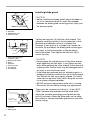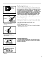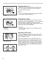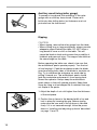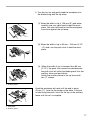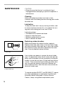
1
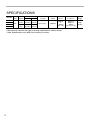
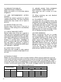
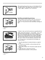
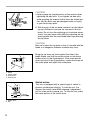
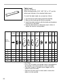
Table Saw
With Electric Brake
210 mm (8-1/4”)
MODEL 2702X1
MODEL 2702
255 mm (10”)
MODEL 2703X1
MODEL 2703
DOUBLE
INSULATION
I N S T R U C T I O N
M A N U A L
WARNING: For your personal safety, READ and UNDERSTAND before using.
SAVE THESE INSTRUCTIONS FOR FUTURE REFERENCE.
w w w. m a k i t a . c o m
SPECIFICATIONS
Blade
MODEL Arbor
hole diameter
2702X1
2702
2703X1
2703
5/8"
Cutting capacities
90°
45°
210mm
68mm
47mm
(8-1/4") (2-11/16") (1-3/4")
255mm
(10")
91mm
(3-9/16")
63mm
(2-1/2")
Maximum dado No load speed Table size
capacity
(RPM)
(W x L)
13 mm (1/2")
4,600/min
686mm
x
560mm
(27" x 22")
• Manufacturer reserves the right to change specifications without notice.
• Note: Specifications may differ from country to country.
2
Dimensions
(L x W x H)
Net
weight
560mm x
686mm x
458mm
(22" x 27" x 18")
18kg
(40 lbs)
For Your Own Safety Read Instruction Manual
Before Operating Table Saw
Save it for future reference
GENERAL SAFETY PRECAUTIONS
(For All Tools)
1. KNOW YOUR POWER TOOL.
Read the owner’s manual carefully. Learn
the tool’s applications and limitations, as
well as the specific potential hazards
peculiar to it.
9. USE RIGHT TOOL.
Don’t force tool or attachment to do a job
for which it was not designed; for example,
don’t use circular saw for cutting tree limbs
or logs.
2. KEEP GUARDS IN PLACE and in working order.
10. WEAR PROPER APPAREL.
Wear no loose clothing, gloves, neckties,
rings, bracelets, or other jewelry which
may get caught in moving parts. Nonslip
footwear is recommended.Wear protective
hair covering to contain long hair.
3. REMOVE ADJUSTING KEYS AND
WRENCHES.
Form habit of checking to see that keys
and adjusting wrenches are removed from
tool before turning it on.
4. KEEP WORK AREA CLEAN.
Cluttered areas and benches invite accidents.
5. DON’T USE IN DANGEROUS
ENVIRONMENT.
Don’t use power tools in damp or wet locations, or expose them to rain. Keep work
area well lighted. Don’t use tool in presence of flammable liquids or gases.
6. KEEP CHILDREN AWAY.
All visitors should be kept safe distance
from work area.
7. MAKE WORKSHOP CHILD PROOF
with padlocks, master switches, or by
removing starter keys.
8. DON’T FORCE TOOL.
It will do the job better and safer at the rate
for which it was designed.
11. ALWAYS USE SAFETY GLASSES.
Also use face or dust mask if cutting operation is dusty. Everyday eyeglasses only
have impact resistant lenses, they are
NOT safety glasses.
12. SECURE WORK.
Use clamps or a vise to hold work when
practical. It’s safer than using your hand
and it frees both hands to operate tool.
13. DON’T OVERREACH.
Keep proper footing and balance at all
times.
14. MAINTAIN TOOLS WITH CARE.
Keep tools sharp and clean for best and
safest performance. Follow instructions for
lubricating and changing accessories.
15. DISCONNECT TOOLS before
servicing; when changing accessories
such as blades, bits, cutters, and the like.
3
16. REDUCE THE RISK OF
UNINTENTIONAL STARTING.
Make sure switch is in off position before
plugging in.
21. NEVER LEAVE TOOL RUNNING
UNATTENDED. TURN POWER OFF.
Don’t leave tool until it comes to a complete stop.
17. USE RECOMMENDED ACCESSORIES.
Consult the owner’s manual for recommended accessories. The use of improper
accessories may cause risk of injury to
persons.
22. When servicing use only identical
replacement parts.
18. NEVER STAND ON TOOL.
Serious injury could occur if the tool is
tipped or if the cutting tool is accidentally
contacted.
19. CHECK DAMAGED PARTS.
Before further use of the tool, a guard or
other part that is damaged should be carefully checked to determine that it will operate properly and perform its intended function - check for alignment of moving parts,
binding of moving parts, breakage of
parts, mounting, and any other conditions
that may affect its operation. A guard or
other part that is damaged should be properly repaired or replaced.
20. DIRECTION OF FEED.
Feed work into a blade or cutter against
the direction of rotation of the blade or cutter only.
23. POLARIZED PLUGS.
To reduce the risk of electric shock, this
equipment has a polarized plug (one blade
is wider than the other). This plug will fit in
a polarized outlet only one way. If the plug
does not fit fully in the outlet, reverse the
plug. If it still does not fit, contact a qualified electrician to install the proper outlet.
Do not change the plug in any way.
VOLTAGE WARNING:
Before connecting the tool to a power
source (receptacle, outlet, etc.) be sure
the voltage supplied is the same as that
specified on the nameplate of the tool. A
power source with voltage greater than
that specified for the tool can result in
SERIOUS INJURY to the user - as well as
damage to the tool. If in doubt, DO NOT
PLUG IN THE TOOL. Using a power
source with voltage less than the nameplate rating is harmful to the motor.
EXTENSION CORDS.
Make sure your extension cord is in good condition. When using an extension cord, be
sure to use one heavy enough to carry the current your product will draw. An undersized
cord will cause a drop in line voltage resulting in loss of power and overheating. Table 1
shows the correct size to use depending on cord length and nameplate ampere rating. If
in doubt, use the next heavier gage. The smaller the gage number, the heavier the cord.
Table 1. Minimum gage for cord
Ampere Rating
4
Total length of cord in feet
Volts
120 V
25 ft.
100 ft.
150 ft.
50 ft.
16
16
14
16
14
12
16
16
14
12
14
12
AWG
More than
Not more than
0
6
18
6
10
18
10
12
12
16
Not Recommended
ADDITIONAL SAFETY RULES
DO NOT let comfort or familiarity with product (gained from repeated use) replace strict
adherence to table saw safety rules. If you use this tool unsafely or incorrectly, you can
suffer serious personal injury.
1. Wear eye protection.
10. NEVER wear gloves during operation.
2. Don’t use the tool in presence of flammable liquids or gases.
11. Keep hands out of the line of the saw
blade.
3. NEVER use the tool with an abrasive
cut-off wheel installed.
12. NEVER stand or permit anyone else to
stand in line with the path of the saw
blade.
4. Check the blade carefully for cracks or
damage before operation. Replace cracked
or damaged blade immediately.
5. Clean the spindle, flanges (especially
the installing surface) and hex nut before
installing the blade. Poor installation may
cause vibration/wobbling or slippage of
the blade.
6. Use saw-blade guard and spreader for
every operation for which it can be used,
including all through sawing operations.
Always assemble and install the blade guard
following the step by step instructions outlined in this manual. Through sawing operations are those in which the blade cuts
completely through the workpiece as in
ripping or cross cutting. NEVER use the
tool with a faulty blade guard or secure the
blade guard with a rope, string, etc. Any
irregular operation of the blade guard
should be corrected immediately.
7. Immediately reattach the guard and
spreader after completing an operation which
requires removal of the guard.
8. Do not cut metals such as nails and
screws.Inspect for and remove all nails,
screws and other foreign matter from the
workpiece before operation.
9. Remove wrenches, cut-off pieces, etc.
from the table before the switch is turned on.
13. Make sure the blade is not contacting
the spreader or workpiece before the
switch is turned on.
14. Before cutting an actual workpiece, let
the tool run for a while. Watch for vibration
or wobbling that could indicate poor installation or a poorly balanced blade.
15. NEVER make any adjustments while
tool is running. Disconnect tool before
making any adjustments.
16. Use a push stick when required. Push
sticks MUST be used for ripping narrow
workpieces to keep your hands and fingers
well away from the blade.
17. Pay particular attention to instructions for
reducing risk of KICKBACK. KICKBACK is a sudden reaction to a pinched, bound or misaligned
saw blade. KICKBACK causes the ejection of
the workpiece from the tool back towards the
operator. KICKBACKS CAN LEAD TO SERIOUS PERSONAL INJURY. Avoid KICKBACKS
by keeping the blade sharp, by keeping the rip
fence parallel to the blade, by keeping the
spreader, antikickback pawls and blade guard
in place and operating properly, by not releasing the workpiece until you have pushed it all
the way past the blade, and by not ripping a
workpiece that is twisted or warped or does not
have a straight edge to guide along the
fence.
5
18. Do not perform any operation freehand.
Freehand means using your hands to support or guide the workpiece, in lieu of a rip
fence or miter gauge.
23. Don’t abuse cord. Never yank cord to
disconnect from receptacle. Keep cord
away from heat, oil, water and sharp
edges.
19. NEVER reach around or over saw
blade. NEVER reach for a workpiece until
the saw blade has completely stopped.
24. Some material contains chemicals
which may be toxic. Take caution to prevent working dust inhalation and skin contact. Follow material supplier safety data.
20. Avoid abrupt, fast feeding. Feed as
slowly as possible when cutting hard workpieces. Do not bend or twist workpiece while
feeding. If you stall or jam the blade in the
workpiece, turn the tool off immediately.
Unplug the tool. Then clear the jam.
25. The guard can be lifted during workpiece setup and for ease of cleaning.
Always make sure that guard hood is
down and flat against sawtable before
plugging in the tool.
21. NEVER remove cut-off pieces near the
blade or touch the blade guard while the
blade is running.
22. Knock out any loose knots from workpiece BEFORE beginning to cut.
SAVE THESE INSTRUCTIONS.
WARNING:
MISUSE or failure to follow the safety rules stated in this instruction manual may cause
serious personal injury.
6
The tool is shipped from the factory with the saw blade
and blade guard not in the installed condition. Assemble
as follows:
ASSEMBLY
CAUTION:
• Always unplug the tool before assembly.
Installing saw blade
Remove the table insert on the table. Hold the outer
flange with the offset wrench and loosen the hex nut
counterclockwise with the wrench. Then remove the
outer flange.
2
3
1
1. Wrench
2. Offset Wrench
3. Hex nut
3
1
4
1.
2.
3.
4.
Outer flange
Hex nut
Inner flange
Saw blade
2
Assemble the inner flange, blade, outer flange and hex
nut onto the arbor, making sure that the teeth of the
blade are pointing down at the front of the table. Always
install the hex nut with its recessed side facing the outer
flange.
CAUTION:
• Keep the flange surface clean of dirt or other adhering
matter; it could cause blade slippage. Be sure that the
blade is installed so that the teeth are aligned in the cutting (turning) direction.
To secure the blade in place, hold the outer flange with
the offset wrench, then tighten the hex nut clockwise
with the wrench. BE SURE TO TIGHTEN THE HEX
NUT SECURELY.
CAUTION:
2
1. Wrench
2. Offset Wrench
1
• Be sure to hold the hex nut carefully with the wrench.
If your grip should slip, the wrench may come off the
hex nut, and your hand could strike the sharp blade
edges.
7
1
Installing blade guard
2
3
CAUTION:
• Before installing the blade guard, adjust the depth of
cut to its maximum elevation. Insert the spreader
between the blade guard mounting portion (stay) and
the pressure plate.
4
1. Blade guard
2. Spreader
3. Antikickback pawl
4. Pressure plate
1
3
6
Tighten the hex bolts (A) with the offset wrench. The
spreader installing location is factory-adjusted so that
the blade and spreader will be in a straight line.
However, if they are not in a straight line, loosen the
hex bolts (B) and adjust the blade guard mounting portion (stay) so that the spreader is aligned directly
behind the blade. Then tighten the hex bolts (B) to
secure the stay.
2
4
5
7
1. These two clearances
should be equal
2. Blade guard portion
3. Blade
4. Spreader
5. Pressure plate
6. Hex bolts(A)
7. Hex bolts(B)
2
4 - 5 mm
(5/32" - 13/64")
1. Spreader
2. Blade guard
8
CAUTION:
• Always grasp the striped portion of the offset wrench
when tightening the hex bolts. If you tighten the hex
bolts while grasping the offset wrench further than the
striped portion, the hex bolts may be damaged and/or
an injury to your hand may result.
• If the blade and spreader are not aligned properly, a
dangerous pinching condition may result during operation. Make sure they are properly aligned. You could
suffer serious personal injury while using the tool without a properly aligned spreader.
• NEVER make any adjustments while tool is running.
Disconnect the tool before making any adjustments.
1
There must be a clearance of about 4 - 5 mm (5/32” 13/64”) between the spreader and the blade teeth.
Adjust the spreader accordingly and tighten the hex
bolts (A) securely. Attach the table insert on the table,
then check to see that the blade guard works smoothly
before cutting.
Positioning table saw
459 mm
(18-1/16”)
334 mm
(13-1/8”)
1
1. Hole diameter 8 mm (5/16”)
1
25 mm (1”)
Locate the table saw in a well lit and level area where
you can maintain good footing and balance. It should
be installed in an area that leaves enough room to easily handle the size of your workpieces. The table saw
should be secured with four screws or bolts to the work
bench or table saw stand using the holes provided in
the bottom of the table saw. When securing the table
saw on the work bench, make sure that there is an
opening in the top of the work bench the same size as
the opening in the bottom of the table saw so the sawdust can drop through.
If during operation there is any tendency for the table
saw to tip over, slide or move, the work bench or table
saw stand should be secured to the floor.
2
1. 6 mm (1/4”) Std. washer
2. No. 10 wood screw 40 mm (1-1/2”)
min. length
NOTE:Table saw stand
• Models 2702X1 and 2703X1 are standard-equipped
with a table saw stand.
1
2
1. 6 mm (1/4”) Std. washer
2. 6 mm (1/4”) Machine bolt & nut
tighten securely
Storing accessories
1
The miter gauge and wrenches can be stored on the
left side of the base and the rip fence can be stored at
the rear of the base.
1. Miter gauge
1
1. Rip fence
9
Adjusting depth of cut
The depth of cut may be adjusted by turning the handle. Turn the handle clockwise to raise the blade or
counterclockwise to lower it.
1
NOTE:
• Use a shallow depth setting when cutting thin materials in order to obtain a cleaner cut.
1. Handle
Adjusting bevel angle
1
2
Loosen the lock lever counterclockwise and turn the
handwheel until the desired angle (0° - 45°) is obtained.
The bevel angle is indicated by the arrow pointer.
After obtaining the desired angle, tighten the lock lever
clockwise to secure the adjustment.
3
CAUTION:
1. Lock lever
2. Handwheel
3. Arrow pointer
• After adjusting the bevel, be sure to tighten the lock
lever securely.
Adjusting positive stops
The tool is equipped with positive stops at 90° and 45°
to the table surface. To check and adjust the positive
stops, proceed as follows:
1
2
1. 90° adjusting screw
2. 45° adjusting screw
(A)
90°
45°
(B)
90°
10
45°
Move the handwheel as far as possible by turning it.
Place a triangular rule on the table and check to see if
the blade is at 90° or 45° to the table surface. If the
blade is at an angle shown in Fig. A, turn the adjusting
screws clockwise; if it is at an angle shown in Fig. B,
turn the adjusting screws counterclockwise to adjust
the positive stops.
After adjusting the positive stops, set the blade at 90° to
the table surface. Then adjust the arrow pointer so that
its right edge is aligned to the 0° graduation.
1
1. Arrow pointer
Installing and adjusting rip fence
Raise the grip of the rip fence. Install the rip fence on
the table so that the fence holder engages with the
guide rail. The rip fence can be secured by lowering the
grip.
1
2
3
1. Fence holder
2. Guide rail
3. Grip
A
B
1
1. Scale
1
2
To check to be sure that the rip fence is parallel with the
blade, secure the rip fence 2 - 3 mm (5/64” - 1/8” ) from
the blade. Raise the blade up to maximum elevation.
Mark one of the blade teeth with a crayon. Measure the
distance (A) and (B) between the rip fence and blade.
Take both measurements using the tooth marked with
the crayon.These two measurements should be identical. If the rip fence is not parallel with the blade, proceed as follows:
1. Turn the adjusting nut counterclockwise a couple of
turns.
2. Loosen the two hex bolts on the rip fence with the
wrench provided.
3. Adjust the rip fence until it becomes parallel with the
blade.
4. Lower the grip to secure the rip fence.
5. Tighten the two hex bolts on the rip fence.
3
1. Hex bolts
2. Adjusting nut
3. Grip
11
CAUTION:
• Always grasp the striped portion of the wrench when
tightening the hex bolts. If you tighten the hex bolts
while grasping the wrench further than the striped portion, the hex bolts may be damaged and/or an injury
to your hand may result.
6. With the grip of the rip fence lowered, turn the adjusting nut clockwise to secure the rear end of the rip
fence. Do not turn the adjusting nut clockwise excessively. You may have some difficulty adjusting the rip
fence parallel with the saw blade when repositioning
the rip fence.
CAUTION:
Be sure to adjust the rip fence so that it is parallel with the
blade, or a dangerous kickback condition may occur.
1
Bring the rip fence up flush against the side of the
blade. Make sure that the arrow pointer on the fence
holder points to the 0 graduation. If the arrow pointer
does not point to the 0 graduation, loosen the screw on
the scale plate and adjust the scale plate.
2
3
4
1. Screw
2. Fence holder
3. Scale plate
4. Arrow mark
1
2
1. Switch lever
2. Key
12
Switch action
This tool is equipped with a special type of switch to
prevent unintentional starting. To start the tool, first
depress the switch lever.While keeping it depressed,
pull its lower portion toward you. To stop the tool, press
the lower portion of the switch lever.
When operating the switch lever, it is convenient to
view it through the window area in the table.
CAUTION:
• When not using the tool, remove the key and store it
in a secure place. This prevents unauthorized operation.
• Before plugging in the tool, always check to see that
the switch lever actuates properly and returns to the
“OFF” position.
• Do not pull the switch lever hard without the key. This
can cause breakage of the switch.
OPERATION
CAUTION:
• Always use “work helpers” such as push sticks and
push blocks when there is a danger that your hands or
fingers will come close to the blade.
• Always hold the workpiece firmly with the table and
the rip fence or miter gauge. Do not bend or twist it
while feeding. If the workpiece is bent or twisted, dangerous kickbacks may occur.
• NEVER withdraw the workpiece while the blade is running. If you must withdraw the workpiece before completing a cut, first switch the tool off while holding the
workpiece firmly. Wait until the blade has come to a
complete stop before withdrawing the workpiece.
Failure to do so may cause dangerous kickbacks.
• NEVER remove cut-off material while the blade is running.
• NEVER place your hands or fingers in the path of the
saw blade. Be especially careful with bevel cuts.
• Always secure the rip fence firmly, or dangerous kickbacks may occur.
• Always use “work helpers” such as push sticks and
push blocks when cutting small or narrow workpieces,
or when the dado head is hidden from view while cutting.
Work helpers
Push sticks, push blocks or auxiliary fence are types of
“work helpers”. Use them to make safe, sure cuts without the need for the operator to contact the blade with
any part of the body.
13
Push stick
(H)
9.5 mm
(3/8”)
130 mm (5”)
75 mm (3”)
19 mm
(3/4”)
9.5 mm (3/8”)
40 mm
(1-1/2”)
50mm (2”)
50 mm
(2”)
380 mm (15”)
A push stick can be easily made from a piece of plywood 19 mm (3/4”) to 25 mm (1”) thick.
Cut out the hatched area on the stick and smooth
edges with a file. (H) dimension should be less than
12.7 mm (1/2”) so as to be thinner than the workpiece.
120 mm
(4-3/4”)
Push block
300 mm (12”)
Use a 19 mm (3/4”) piece of plywood.
130 mm
(5”)
1
6 mm (1/4”)
2
50mm (2”)
300 mm (12”)
130 mm
(5”)
50 mm
(2”)
3
9.5 mm (3/8”)
100 mm (4”)
4
50 mm (2”)
1.
2.
3.
4.
8 mm (5/16”)
Face/edge parallel
Handle
Wood screw
Glue together
9.5 mm
(3/8”)
19 mm
(3/4”)
120 mm
(4-3/4”)
40 mm
(1-1/2”)
1
460 mm (18”)
140 mm
(5-1/2”)
Fasten with glue and wood screws.
1. Face/edge parallel
14
Handle should be in center of plywood piece. Fasten
with glue and wood screws as shown. Small piece 9.5
mm x 8 mm x 50 mm (3/8” x 5/16” x 2”) of wood must
always be glued to plywood to keep the blade from
dulling if the operator cuts into push block by mistake.
(Never use nails in push block.)
Auxiliary fence
Make auxiliary fence from 9.5 mm (3/8”) and 19 mm
(3/4”) plywood pieces.
Wood facing (rip fence)
A wood facing should be used for operations when the
blade comes close to the rip fence. Wood facing for the rip
fence should be the same size as the rip fence. Make sure
the bottom of facing is flush with the table surface.
1
1. No. 10 wood screws (long enough
to penetrate halfway into facing)
Crosscutting
CAUTION:
• When making a crosscut, remove the rip fence from
the table.
• When cutting long or large workpieces, always provide
adequate support to the sides of the table. The support should be at the same height as the table.
• Always keep hands away from path of blade.
Miter gauge
1
2
3
4
Use the miter gauge for the 4 types of cutting shown in
the figure.
CAUTION:
1.
2.
3.
4.
• Secure the knob on the miter gauge carefully.
• Avoid creep of workpiece and gauge by firm workholding arrangement, especially when cutting at an angle.
• NEVER hold or grasp the intended “cut-off” portion of
the workpiece.
CROSS CUTTING
MITERING
BEVEL CUTTING
COMPOUND MITERING
(ANGLES)
Use of miter gauge
1
2
3
Slide the miter gauge into the thick grooves in the table.
Loosen the knob on the gauge and align to desired
angle (0° to 60°). Bring stock flush up against fence and
feed gently forward into the blade.
1. Groove
2. Miter gauge
3. Knob
15
Auxiliary wood facing (miter gauge)
To prevent a long board from wobbling, fit the miter
gauge with an auxiliary fence board. Fasten with
bolts/nuts after drilling holes, but fasteners must not
protrude from the face board.
Ripping
CAUTION:
• When ripping, remove the miter gauge from the table.
• When cutting long or large workpieces, always provide
adequate support behind the table. DO NOT allow a
long board to move or shift on the table. This will
cause the blade to bind and increase the possibility of
kickback and personal injury. The support should be at
the same height as the table.
Before operating the table saw, check to be sure that
the antikickback pawls operate properly. Turn the tool
off and unplug it. Feed the workpiece under the blade
guard and along both sides of the blade to simulate cutting. Try to withdraw the workpiece on each side by
pulling it toward you. The antikickback pawls should
grab the workpiece and prevent it from moving back
toward the operator. Always keep the antikickback
pawls sharp so they will operate properly. Keep them
sharp by using a round-shaped file to maintain the original shape of the pawls.
1. Adjust the depth of cut a bit higher than the thickness
of the workpiece.
2. Position the rip fence to the desired width of rip and
lock in place by lowering the grip. Before ripping,
make sure the rear end of the rip fence is secured
firmly. If it is not secured enough, follow the procedures in “Installing and adjusting rip fence” described
on page 11 and 12.
16
3. Turn the tool on and gently feed the workpiece into
the blade along with the rip fence.
(1) When the width of rip is 150 mm (6”) and wider,
carefully use your right hand to feed the workpiece. Use your left hand to hold the workpiece
in position against the rip fence.
(2) When the width of rip is 65 mm - 150 mm (2-1/2”
- 6”) wide, use the push stick to feed the workpiece.
1
1. Push stick
1
(3) When the width of rip is narrower than 65 mm
(2-1/2”), the push stick cannot be used because
the push stick will strike the blade guard. Use the
auxiliary fence and push block.
Attach the auxiliary fence to the rip fence with
two “C” clamps.
1. Auxiliary fence
1
Feed the workpiece by hand until the end is about
25 mm (1”) from the front edge of the table. Continue
to feed using the push block on the top of the auxiliary
fence until the cut is complete.
2
1. Push block
2. Auxiliary fence
17
MAINTENANCE
CAUTION:
• Always be sure that the tool is switched off and
unplugged before attempting to perform inspection or
maintenance.
Cleaning
Clean out sawdust and chips from time to time.
Carefully clean the blade guard and moving parts inside
the table saw.
Lubrication
To keep the table saw in tip-top running condition, and
to assure maximum service life, oil or grease the moving parts and rotating parts from time to time.
Lubrication places:
• Threaded shaft to elevate the blade
• Hinge to rotate the frame
• Elevation guide shafts on motor
• Gear to elevate the blade
Replacing carbon brushes
Remove and check the carbon brushes regularly.
Replace when they wear down to the limit mark. Keep
the carbon brushes clean and free to slip in the holders.
Both carbon brushes should be replaced at the same
time. Use only identical carbon brushes.
1
1. Limit mark
1
2
Use a holder cap opener to remove the brush holder
caps. To replace the carbon brush in the side near the
table, lower the blade as far as possible by turning the
handle. Loosen the lock lever, tilt the blade and secure
it at 45°. Then loosen the brush holder cap while viewing it through the opening of the base. Remove the
worn carbon brushes, insert the new ones and secure
the brush holder caps.
1. Holder cap opener
2. Brush holder cap
To maintain product SAFETY and RELIABILITY, repairs,
any other maintenance or adjustment should be performed by Makita Authorized or Factory Service
Centers, always using Makita replacement parts.
18
CAUTION:
ACCESSORIES
• These accessories or attachments are recommended
for use with your Makita tool specified in this manual.
The use of any other accessories or attachments
might present a risk of injury to persons.
Only use accessory or attachment for its stated purpose.
Dado head set (Part No. 191543-4)
A dado is cutting a rabbet or a wide groove into the
workpiece. The dado head set consists of two outside
cutters, three inside cutters and paper washers.
1/8”
1/8”
1/16”
1/8”
1/8”
Outside cutters: 6”diameter, 1/8” thick, 5/8”arbor hole, 2 pcs.
Inside cutters: 6”diameter, 1/8”thick, 5/8”arbor hole, 2 pcs.
Inside cutter: 6”diameter, 1/16”thick, 5/8”arbor hole, 1 pc.
Paper washers:
5/8”arbor hole, 6 pcs.
Various combinations of these cutters are used to cut
grooves from 1/8” to 1/2” for use in making joints,
tenoning, grooving, etc.
1
2
3
4
Dado flange set (Part No. 192693-8)
1. Dado outer flange
When cutting groove 1/4”, 5/16”, 3/8”, 7/16” or 1/2” ,
use this dado outer flange.
2. Dado hex nut
When cutting groove 1/4”, 5/16”, 3/8”, 7/16” or 1/2” ,
use this dado hex nut.
3. Ring
When cutting groove 1/4”, 5/16”, 3/8”, 7/16” or 1/2” ,
use this ring.
4. Washer
When cutting groove 1/4”, 5/16” or 3/8”, use this
washer.
19
Table insert
(Part No. 317061-6)
When cutting grooves 5/16”, 3/8”,7/16” or 1/2” use this
table insert instead of the standard table insert.
To install the dado head set, proceed as follows:
1. Turn the tool off and unplug it before installing.
2. Remove the blade guard with the spreader.
3. Install the dado head set with the teeth pointing down
at the front of the table.
4. Use the chart below to select the proper cutters to
obtain the various cutting widths.
Spindle
Outside
Inner
Ring
flange
Cutter
1/8"
Inside
cutter
1/16"
Inside
cutter
Outside
cutter
Outer
flange
Dado
Dado
Hex
Hex
nut
flange
nut
Washer Outer
CUT
WIDTH
1/8"
1/4"
5/16"
3/8"
7/16"
1/2"
•
•
•
•
•
•
•
•
•
•
•
•
•
•
•
• •
• •
• •
x2
•
•
•
•
•
•
•
•
•
•
•
•
•
•
•
•
•
•
•
•
•
•
CAUTION:
• For a 1/8” cut width, the outside cutter is assembled to
the spindle in the same manner as the saw blade.
• The outer flange or the dado outer flange must be
used for each cut width.
• The hex nut alone must not be used to secure the
dado on to the spindle.
20
NOTE:
• When widths slightly greater than the above are
required, fit the paper washers in between the inside
and outside cutters to adjust the width.
1
2
5. Arrange the cutters so that the tips of the inside cutters are positioned at the gullets of the outside cutter.
When more than one inside cutter is used, space
the tips of the inside cutters equidistantly in relation
to one another. Poorly spaced cutters may cause
vibration and noise.
3
1. Inside cutter
2. Outside cutter
3. Gullet
When installing two outside cutters without any inside
cutter, be sure that the cutter tips do not face each
other.
6. While tightening the hex nut, be careful to maintain the
even spacing between the tips of the inside cutters.
7. Rotate the dado head one turn by hand to make sure
that it does not contact anything before operation.
200 mm(8”)
600 mm(24”)
1
19 mm
(3/4”)
When dadoing, use featherboards. The diagram shown
illustrates dimensions for making a typical featherboard.
It should be made from a straight piece of wood that is
free of knots or cracks.
130 mm
(5”)
115 mm
(4-1/2”)
1. Kerf should be about 6 mm
(1/4”) apart
21
1
2
Featherboards are used to keep the workpiece in contact with the rip fence and table as shown, and to stop
kickbacks.
To install featherboards, proceed as follows:
4
3
1.
2.
3.
4.
“C”Clamps
Facing board
Featherboard
Push stick
1. Turn the tool off and unplug it.
2. Add 8” high flat facing board to the rip fence, the full
length of the rip fence.
3. Mount featherboards to the rip fence and table as
shown, so that the leading edges of the featherboards will support the workpiece until the cut is
completed, and the workpiece has been pushed
completely past the cutter with a push stick.
4. Make sure featherboards are securely attached.
CAUTION:
• Only the Makita dado head set (Part No. 191543-4)
should be used with Makita table saw Model
2702/Model 2703. Do not use dado combinations
wider than 13 mm (1/2").
• After dadoing, ALWAYS replace the blade guard with
the spreader back in its original position on the table
saw.
• NEVER attempt bevel cuts when dadoing.
• NEVER dado if there is vibration (flutter) or a strange
noise.
• NEVER attempt dados in other than wood.
• Do not use the dado set for cut-offs.
• Feed work slowly, especially when cutting deep or wide
grooves or dados. If a deep cut is needed, make several
passes through the workpiece rather than one deep,
wide cut. Fast or abrupt feeds can be dangerous.
• Use a push stick. When the dado head is hidden from
view while cutting, your hands should never be on top
of the stock.
• A very dangerous throwback can result if the wood
becomes stuck and you try to remove it by pulling
toward you. Always stop the tool and wait for dado
head to come to a complete stop. Then simply withdraw the wood.
WARNING:
• Use extra caution when the guard assembly is
removed for any non-through sawing operation such
as dadoing, rabbeting or resawing. Replace guard
immediately after non-through sawing is completed.
22
1
How to perform rabbeting
3
2
1. Rabbet
2. First cut
3. Second cut
1. Remove blade guard.
2. Attach auxiliary fence to rip fence for cuts that run the
length of the stock. Facing should be as high as the
workpiece is wide. Adjust fence and blade to desired
dimensions.
3. First cut: Hold board flat on table as in ordinary ripping.
4. Second cut: Set workpiece on its edge. (Use featherboards, push stick, push block and so on, using precautions, safety rules and guidelines for ripping or
related work.)
5. For end-type rabbeting, if the workpiece is less than
10-1/2” wide, rest the wood flat on the table against
the miter gauge (with wood facing). The rip fence
should not be used.
6. After rabbeting is completed, immediately re-install
the blade guard as before.
Table saw stand (Part No. 192680-7)
1
3
2
Place the stays on a level location and assemble the
legs inside. Secure with the bolts and nuts, then attach
the rubber caps to the ends of the legs.
4
5
1.
2.
3.
4.
5.
Rubber cap
Nut
Leg
Under stay
Stay
1
Now set the table saw on top of the assembled stand
and secure with four bolts, washers and nuts.
NOTE:
• Models 2702X1 and 2703X1 are standard-equipped
with a table saw stand.
2
1. Bolt
2. Stand
23
ACCESSORIES
CAUTION:
• These accessories or attachments are recommended
for use with your Makita tool specified in this manual.
The use of any other accessories or attachments
might present a risk of injury to persons. Only use
accessory or attachment for its stated purpose.
If you need any assistance for more details regarding
these accessories, ask your local Makita service center.
• Steel & Carbide-tipped saw blades
Table/Miter saw
blades
Combination
Fine cross cuts
•
•
•
•
•
•
•
•
24
For general purpose cuts for
table and miter saws.
General purpose blade for fast and
smooth rip, crosscuts and miters.
For sand-free cuts cleanly against
the grain.
Sub-Table set ( Left / Right )
Rip fence
Miter gauge
Offset wrench 13-22
Wrench 19
Key (Switch button)
Holder cap opener
Joint ( for connecting to dust collector )
Cut
First-Class
Postage
Required
Post Office will
not deliver
without proper
postage.
Makita U.S.A., Inc.
14930 Northam Street
La Mirada, CA 90638-5753
Fold
21
MAIL THIS PORTION
Your answers to the following questions are appreciated.
1. This product was purchased from:
Home Center
3. How did you learn about this product:
Magazine
Radio
Hardware/Lumber Store
From Dealer
Exhibition
Tool Distributor
Newspaper
From Friend
Industrial Supply
Store Display
Previous Usage
Construction Supply
Catalog
Other (
Other (
)
2. Use of the product is intended for:
)
4. Most favored points are:
Construction Trade
Design
Repair Service
Industrial Maintenance
Features
Durability
Home Maintenance
Size
Power
Hobby
Price
Other (
Other (
)
)
Makita Brand
5. Any comments:
YEAR
SERIAL NO.
SEX
STATUS
INTL.
LAST NAME / COMPANY NAME
Married Single
M
F
Paste
STREET ADRESS
AGE:
ZIP CODE
Under 19
AREA
CODE
PHONE
20-29
30-39
40-49
50-60
Paste
Paste
CITY
STATE
Paste
Paste
MODEL NO.
DAY
Over 60
Paste
MONTH
Paste
Paste
Paste
Paste
DATE PURCHASED
Paste
Paste
BE SURE TO COMPLETE THE CUSTOMER’S PORTION OF THIS FORM AND RETAIN FOR YOUR RECORDS.
Please return this portion by facsimile or mail.
22
Facsimile No: (714) 522-8133
Paste
Paste
Paste
Paste
Paste
Paste
Paste
Paste
FACTORY SERVICE CENTERS
1-800-4-MAKITA
RETAIN THIS PORTION FOR YOUR RECORDS
ALABAMA
2365 Pelham Parkway
Pelham, AL 35124
(205) 620-1791
COLORADO
11839 E. 51st Ave.
Denver, CO 80239-2709
(303) 371-2850
LOUISIANA
5626 Jefferson Hwy.
Harahan, LA 70123
(504) 733-4138
ARIZONA
3707 E. Broadway Rd., Ste. 6
Phoenix, AZ 85040
(602) 437-2850
FLORIDA
620 Douglas Ave. Suite 1302
Altamonte Springs, FL 32714
(407) 774-6000
MARYLAND
7541 - 45 Ritchie Highway
Glen Burnie, MD 21061
(410) 590-0160
ARKANSAS
Shackleford Shopping Center
240 South Shackleford Rd.,
Ste. C
Little Rock, AR 72211
(501) 224-5733
CALIFORNIA
41850 Christy St.
Fremont, CA 94538-5107
(510) 657-9881
1421 N. Clovis Ave., Ste. 112
Fresno, CA 93727
(559) 252-5166
14930 Northam St.
La Mirada, CA 90638-5753
(714) 522-8088
1970 Fulton Avenue
Sacramento, CA 95825
(916) 482-5197
1440 South “E” Street
San Bernardino, CA 92408
(909) 885-1289
7674 Clairemont Mesa Blvd.
San Diego, CA 92111
(858) 278-4471
1565 Winchester B.
Campbell, CA 95008-0501
(408) 379-0377
750 East Sample Road
Pompano Beach, FL 33064
(954) 781-6333
Thompson Center Waters
5501 W. Waters Ave., Ste. 406
Tampa, FL 33634
(813) 886-8292
GEORGIA
4680 River Green Parkway
Duluth, GA 30096-2566
(770) 476-8911
ILLINOIS
1450 Feehanville Dr.
Mt. Prospect, IL 60056-6011
(847) 297-3100
INDIANA
8403 Michigan Road, Unit 1
Indianapolis, IN 46268
(317) 334-9980
KANSAS
8819 W. 95th St.
Overland Park, KS 66212
(913) 642-1111
KENTUCKY
1215 S. Hurstbourne Parkway
Louisville, KY 40222
(502) 326-3740
MASSACHUSETTS
232 Providence Hwy.
Westwood, MA 02090
(617) 461-9754
MINNESOTA
6427 Penn Ave. South
Richfield, MN 55423
(612) 869-5199
NEW YORK
4917 Genessee Street
Cheektowaga, NY 14225
(716) 685-9503
131-35 31st Ave.
Flushing, NY 11354
(718) 886-0971
NORTH CAROLINA
3501-G S. Tryon St.
Charlotte, NC 28217
(704) 527-0611
TEXAS
12801 Stemmons Fwy Ste. 809
Farmers Branch, TX 75234
(972) 243-1150
12701 Directors Dr.
Stafford, TX 77477-3701
(281) 565-8665
6379 Pearl Road
Parma Heights, OH 44130
(440) 843-7555
3453 IH-35 North, Ste. 101
San Antonio, TX 78219
(210) 228-0676
1617 E. Kemper Rd.
Sharonville, OH 45246
(513) 771-0788
NEBRASKA
4129 S. 84th St.
Omaha, NE 68127
(402) 597-2925
OKLAHOMA
552 E. Memorial Road
Oklahoma City, OK 73114
(405) 752-2655
NEVADA
3375 S. Decatur Blvd.
Suites. 22 - 24
Las Vegas, NV 89102
(702) 368-4277
OREGON
828 19th Avenue., N.W.
Portland, OR 97209
(503) 222-1823
16735 Saticoy St., Ste. 105
Van Nuys, CA 91406
(818) 782-2440
TENNESSEE
4655 Nolensville Rd.
Nashville, TN 37211
(615) 331-9922
OHIO
6253 E. Main St.
Columbus, OH 43213
(614) 860-0222
MISSOURI
9876 Watson Road
St. Louis, MO 63126-2221
(314) 909-9889
NEW JERSEY
251 Herrod Blvd.
Dayton, NJ 08810-1539
(609) 655-1212
PUERTO RICO
200 Guayama St.
Hato Rey, PR 00917
(787) 250-8776
PENNSYLVANIA
Springwater Plaza
364 Wilmington W. Chester
Pike
Glen Mills, PA 19342
(610) 459-4122
UTAH
145 E. 1300 S., Ste. 101
Salt Lake City, UT 84115
(801) 359-3410
WASHINGTON
22220 84th Ave. So., Bldg. A
Kent, WA 98032
(253) 395-8055
WISCONSIN
Lincoln Plaza Shopping Ctr.
2245 S. 108th St. West Allis, WI
53227
(414) 541-4776
6200 Babcock Blvd
Pittsburgh, PA 15237
(412) 366-6363
CUSTOMER’S RECORD
When you need service: Send
complete tool (prepaid) to one
of the Makita Factory Service
Centers listed, or to an Authorized
Makita Service Center. Be sure
to attach a letter to the outside of
the carton detailing the problem
with your tool.
Date Purchased
Dealer’s Name & Address
Model No.
Serial No.
27
WARNING
Some dust created by power sanding, sawing, grinding, drilling, and other
construction activities contains chemicals known to the State of California
to cause cancer, birth defects or other reproductive harm. Some examples
of these chemicals are:
• lead from lead-based paints,
• crystalline silica from bricks and cement and other masonry products, and
• arsenic and chromium from chemically-treated lumber.
Your risk from these exposures varies, depending on how often you do this
type of work. To reduce your exposure to these chemicals: work in a well
ventilated area, and work with approved safety equipment, such as those
dust masks that are specially designed to filter out microscopic particles.
MAKITA LIMITED ONE YEAR WARRANTY
Warranty Policy
Every Makita tool is thoroughly inspected and tested before leaving the factory. It is warranted to be free of
defects from workmanship and materials for the period of ONE YEAR from the date of original purchase.
Should any trouble develop during this one year period, return the COMPLETE tool, freight prepaid, to one of
Makita’s Factory or Authorized Service Centers. If inspection shows the trouble is caused by defective
workmanship or material, Makita will repair (or at our option, replace) without charge.
This Warranty does not apply where:
• repairs have been made or attempted by others:
• repairs are required because of normal wear and tear:
• the tool has been abused, misused or improperly maintained:
• alterations have been made to the tool.
IN NO EVENT SHALL MAKITA BE LIABLE FOR ANY INDIRECT, INCIDENTAL OR CONSEQUENTIAL
DAMAGES FROM THE SALE OR USE OF THE PRODUCT. THIS DISCLAIMER APPLIES BOTH DURING
AND AFTER THE TERM OF THIS WARRANTY.
MAKITA DISCLAIMS LIABILITY FOR ANY IMPLIED WARRANTIES, INCLUDING IMPLIED WARRANTIES OF
“MERCHANTABILITY” AND “FITNESS FOR A SPECIFIC PURPOSE,” AFTER THE ONE YEAR TERM OF THIS
WARRANTY.
This Warranty gives you specific legal rights, and you may also have other rights which vary from state to state.
Some states do not allow the exclusion or limitation of incidental or consequential damages, so the above
limitation or exclusion may not apply to you. Some states do not allow limitation on how long an implied
warranty lasts, so the above limitation may not apply to you.
Makita Corporation of America
2650 Buford Hwy., Buford, GA 30518
884129C060