1
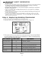
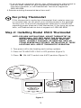
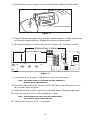
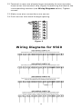
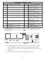
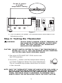
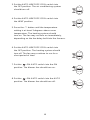
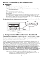
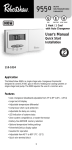
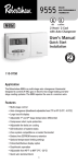
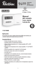
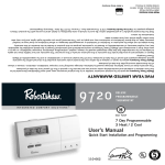
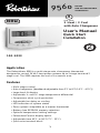
9560
®
DELUXE
NON-PROGRAMMABLE
THERMOSTAT
H
NeW
HEAT PUMP
2 Heat / 2 Cool
with Auto Changeover
User's Manual
YEA
WO
2
WA
R
T
Quick Start
Installation
RRANTY
110-1033
Application
The Robertshaw 9560 is a multi-stage auto changeover thermostat
designed to control 24 VAC heat pump systems up to 2 stage heat and 2
stage cool. The 9560 requires the use of a common wire.
Features
• Multi-stage control
• Auto changeover [deadband adjustable from 2°F to 8°F (1.0°C - 4.5°C)]
• Large back lit display
• Adjustable 1ST and 2ND stage temperature differential
• Compressor short cycle protection
• Adjustable fan delay on cooling
• LED indication of system status
• Zone system compatible as a master thermostat
• Battery-free EEPROM memory retention
• Optional temperature limiting settings
• Fahrenheit/Celsius display option
• Adjustable from 45°F to 90°F (7°C - 32°C)
• Quick wire terminal block
1
! IMPORTANT SAFETY INFORMATION
WARNING:
• Always turn off power at the main power source by unscrewing fuse
or switching circuit breaker to the off position before installing,
removing, cleaning, or servicing thermostat.
• Read all the information in this manual before installing or programming this thermostat.
• This is a 24 VAC low-voltage thermostat. Do not install on voltages
higher than 30 VAC.
• All wiring must conform to local and national building and electrical
codes and ordinances.
• Do not short (jumper) across terminals on the gas valve or at the
system control to test installation. This will damage the thermostat
and void the warranty.
Step 1: Replacing Existing Thermostat
1. Turn off power to heating and cooling system.
2. Remove cover from old thermostat to expose wires (Figure 1).
Figure 1
3. Disconnect wires one at a time from existing terminals. Use enclosed labels
to mark existing wires. Refer to cross references in Table 1 if existing wiring
does not directly match the labels.
Old Terminal
New Label
Description
L
L
System Check
R, V-VR or VR-R
R
24 VAC, Return
Y, Y1 or M
Y1
1st Stage Cooling Control
O or R
O
Cool Active Reversing Valve
B
B
Heat Active Reversing Valve
F or G
G
Fan Control Relay
Y2
Y2
2nd Stage Cooling Control
W2 or W-U
W2
2nd Stage Heating Control
C, X or B
C
24 VAC, Transformer Common Side
W1 or W
E
Emergency Heating Relay
NOTE: THIS THERMOSTAT REQUIRES A 24V COMMON WIRE FOR PROPER OPERATION.
Table 1
2
• If you have any questions about cross referencing the old terminal to
the new label, reference your equipment installation manual, a
licensed contractor, or call Robertshaw Technical Support at
(800) 445-8299.
4. Remove existing thermostat base from wall.
Recycling Thermostat
If this thermostat is replacing a thermostat that contains mercury
in a sealed tube, do not place your old thermostat in the garbage.
Contact your local waste management authority for instructions
regarding proper disposal of the thermostat. If you have any questions, call Robertshaw technical support at 1-800-445-8299.
Step 2: Installing Model 9560 Thermostat
NOTE: FOR NEW INSTALLATIONS, MOUNT THERMOSTAT ON
INSIDE WALL, FIVE FEET ABOVE THE FLOOR. DO NOT
INSTALL BEHIND A DOOR, IN A CORNER, NEAR AIR
VENTS, IN DIRECT SUNLIGHT, OR NEAR ANY HEAT OR
STEAM GENERATING FIXTURES. INSTALLATION AT THESE
LOCATIONS WILL AFFECT THERMOSTAT OPERATION.
1. Turn power off to the heating and cooling systems.
2. Place AUTO-HEAT-OFF-COOL in OFF position (Figure 2).
-ON-AUTO switch into AUTO position (Figure 2).
Maple Chase Company
www.maplechase.com
Tech Service: 1-800-445-8299
M-F 7:30 a.m. - 5:30 p.m. CST
MADE IN MEXICO
TM
Item
9555
3. Place
SETTING OR CHANGING THE SETPOINT TEMPERATURE:
1. Press or button. Display will show SET and the current
temperature setpoint.
2. Press or button to adjust temperature setpoint.
3. After completing the change, the display will return to the current
room temperature after a few seconds.
CHANGING THE TEMPERATURE DIFFERENTIAL,
DEAD BAND, AND RESIDUAL COOL:
The temperature differentials are factory set at 1˚F and 2˚F for
1ST and 2ND stages respectively. The dead band for Autochangeover is set at 3˚F. To change settings:
1. Press the and buttons at the same time and hold for 1
second. Display will indicate: DIFFERENTIAL 1ST.
2. Press either the or button to adjust the 1st stage differential between 0.5˚F – 3˚F (0.5˚C - 1.5˚C).
3. Either wait five seconds or press the
button. The display
will indicate: DIFFERENTIAL 2ND.
4. Press either the or button to adjust 2nd stage differential between 1˚F – 6˚F (1˚C - 3˚C).
5. Either wait five seconds or press the
button. The display
will indicate: DEADBAND.
6. Press either the or button to adjust the dead band
between 3˚F – 6˚F (1.5˚C - 3˚C).
7. Either wait five seconds or press the
button. The fan
icon and ON will be displayed.
8. Press either the or button to adjust the Residual Cool
fan delay between 0, 30, 60, or 90 seconds.
9. The display will return to the current room temperature after
a few seconds.
120-1523
AU X
CHECK
EMER
Figure 2
3
4. Remove the cover using a coin or screwdriver (Figure 3). Set aside.
Figure 3
5. Place thermostat against the wall at desired location. Make sure wires
will feed through opening (Figure 4) on base of thermostat.
6. Mark placement of mounting holes (Figure 4). Set base aside.
Mounting Holes
E
Y1 B
WIRING
OPENING
O
G W2 Y2
RESET
NORMAL
EMER HEAT
Figure 4
7. If mounting on drywall, tap plastic anchors into wall.
NOTE: ENCLOSED PLASTIC ANCHORS DO NOT REQUIRE A
DRILLED HOLE FOR DRYWALL.
8. Drill the marked holes using a 3/16" drill bit if mounting on a surface other than drywall.
9. Align base with plastic anchors and feed wires through opening.
10. Secure base to wall with supplied screws.
NOTE: THE THERMOSTAT WILL MOUNT HORIZONTALLY
ON A SINGLE GANG JUNCTION BOX.
11. Strip end of wires 5/16” if needed.
4
12. Terminal screws are already loose and ready for wire insertion.
Insert wires into terminal strip (Figure 5) matching the label to the
corresponding terminal (see Wiring Diagrams below). Tighten
screws.
13. Make sure wire connections are secure.
14. Push access wire back through opening.
E
E
Y1 B
O
G W2 Y2
Figure 5
Wiring Diagrams for 9560
5
TERMINAL LEGEND - 9560
TERM
EQUIPMENT TO CONNECT
REQ?
TERMINAL FUNCTION
C
24VAC common connection
Yes
For input of 24VAC common
side of transformer
L
System fault indicator connection
No
For input of system fault
indicator (if present)
R
24VAC hot connection
Yes
For input of 24VAC hot side
of transformer
Y2
Second stage cooling connection
No
Energizes on a call for
second stage cooling
Y1
First stage compressor connection Yes
Energizes on a call for first
stage heating or cooling
E
Emergency heat connection
No*
Energizes on a call for heat
in the EM mode only
G
Indoor fan connection
Yes
Energizes with E, Y1, Y2 and
W2 terminals or with FAN
option switched to the
ON position
W2
Second stage heat connection
No*
Energizes on a call for
second stage heating
(auxiliary heat)
O
Cool active reversing valve
connection
Yes**
Energizes when in the in
COOL mode
B
Heat active reversing valve
connection
Yes**
Energizes when in the
HEAT or EM modes
*
For systems using a backup heat source. If separate E terminal connection is not available,
jumper E and W2.
** Most heat pump systems will have a cool active OR heat active reversing valve. Use the
appropriate terminal.
E
Y1 B
WIRING
OPENING
O
G W2 Y2
RESET
NORMAL
EMER HEAT
Figure 6
15. A temperature limiting jumper has been included in this thermostat. Cutting this jumper (J3) limits the heating setpoint to no
greater than 72°F and the cooling setpoint to no lower than 78°F
(Figure 7).
16. Replace thermostat cover by snapping into place.
6
Cut the J3 jumper
to enable
temperature limiting
E
Y1 B
WIRING
OPENING
O
G W2 Y2
RESET
NORMAL
EMER HEAT
Figure 7
17. Turn on power to system. Test thermostat as described in the
following section.
Step 3: Testing the Thermostat
! WARNING:
DO NOT SHORT (JUMPER) ACROSS TERMINALS OF
GAS VALVE OR SYSTEM CONTROL TO TEST OPERATION. THIS WILL DAMAGE THE THERMOSTAT
AND VOID YOUR WARRANTY.
CAUTION: DO NOT SWITCH SYSTEM TO COOL IF THE TEMPERATURE IS
BELOW 50°F (10°C). THIS CAN DAMAGE THE AIR CONDITIONING SYSTEM AND CAUSE PERSONAL INJURY.
1. Place the AUTO-HEAT-OFF-COOL switch into
the COOL position.
2. Press the button until the temperature setting
is at least 3 degrees below the room temperature.
The air conditioning system should turn on within
a few seconds.
NOTE: ONCE THE THERMOSTAT TURNS OFF WHEN IN THE COOL MODE, A
BUILT IN 5-MINUTE DELAY PREVENTS THE SYSTEM FROM TURNING ON AGAIN. THIS PROTECTS THE COMPRESSOR. NO ADDITIONAL TIME DELAY RELAY IS REQUIRED. TO OVERRIDE THE 5MINUTE DELAY FOR INSTALLATION, PRESS THE RESET BUTTON.
7
3. Put the AUTO-HEAT-OFF-COOL switch into
the OFF position. The air conditioning system
should turn off.
4. Put the AUTO-HEAT-OFF-COOL switch into
the HEAT position.
5. Press the button until the temperature
setting is at least 3 degrees above room
temperature. The heating system should
turn on. The fan may not turn on immediately,
depending on the fan delay built into the furnace.
6. Put the AUTO-HEAT-OFF-COOL switch into
the OFF position. The heating system should
turn off. The fan may continue to run for a
short period of time.
7. Put the
-ON-AUTO switch into the ON
position. The blower fan should turn on.
8. Put the
-ON-AUTO switch into the AUTO
position. The blower fan should turn off.
8
Step 4: Customizing the Thermostat
◆ Settings
System
Cool: The thermostat controls the cooling.
Off: The heating and cooling systems are off.
Heat: The thermostat controls the heat.
AUTO:The thermostat automatically selects heat or cool depending
on the temperature.
Fan
Auto: Equipment controls the fan.
On: The fan operates continuously.
Temperature
The default setpoint temperature for heating is 70°F (21°C), for cooling is 78°F (25°C), and for auto is 72°F (22°C). After putting the system switch in heat, cool, or auto, press either the or button to
adjust the temperature setting up or down.
The display will return to the current room temperature five seconds after
the last input and the new setpoint will be saved.
AU X
CHECK
EMER
Figure 8
◆ Temperature Differential and Deadband
The temperature differential is factory set at 1°F (0.5°C) for the 1ST stage
differential and 2°F (1.0°C) for the 2ND stage. This means that whenever
the room temperature changes by one degree Fahrenheit from the temperature setting, the system will turn on. If the system turns on too
often, increase the temperature differential.
The 2ND stage will turn on when the room temperature changes from the
desired temperature by the sum of the 1ST and 2ND stage differential settings. The 2ND stage will also turn on if the temperature has not increased
(or decreased in the event of cooling) for a period of twenty minutes.
Although programmed at the same time as the temperature differentials,
the deadband is used only during the AUTO mode. In the AUTO mode, the
thermostat will automatically cycle either the heating or cooling system to
maintain optimal comfort. The deadband is the minimum allowable temperature which must occur to switch to the opposite mode. For example, if
the deadband is set at 3°F and the setpoint is set at 70°F, the thermostat
will switch to cooling mode when the temperature reaches 73°F.
NOTE: IF THE TEMPERATURE LIMITING JUMPER J3 IS CUT
(FIGURE 7), THE DEADBAND IS NOT ADJUSTABLE AND IS
AUTOMATICALLY SET TO 6°F (3°C).
9
◆ Changing Fahrenheit (F) to Celsius (C),
Temperature Differential, Deadband,
and Residual Cool
The temperature differential is factory set at 1°F (0.5°C) for the 1ST stage
differential and 2°F (1.0°C) for the 2ND stage. The deadband for auto
changeover is set at 3°F (1.5°C). To change settings:
1. The thermostat is preset to display the temperature in degrees
Fahrenheit (U.S. models) or degrees Celsius (Canadian models). The
temperature display can be changed. Press and hold both the or
A buttons for three seconds. The display will read F or C. Release
the buttons. Press either the or button to change the display.
2. After three seconds, the display will switch to the differential
settings. The display will read DIFFERENTIAL 1ST.
3. The temperature differential is factory set at 1°F (0.5°C) for the first
stage. Press either the or button to adjust the 1ST stage
differential between 0.5°F - 3°F.
4. Either wait three seconds or press the
button. The display will
indicate: DIFFERENTIAL 2ND.
5. The 2nd stage differential is factory set at 2°F (1.5°C). Press either
the or button to adjust the 2nd stage temperature differential
between 1°F - 6°F (1°C - 3°C).
6. Press the or button to adjust the 2nd stage timed differential
between 5 to 40 minutes. Either wait 5 seconds or press the
button.
7. Either wait three seconds or press the
button. The display will
indicate: AUTOCHANGE DEADBAND.
8. Press either the or button to adjust the deadband between
2°F - 8°F (1.0°C - 4.5°C).
9. Either wait three seconds or press the
button. The fan icon and
ON will be displayed.
10. Press either the or button to adjust the residual cool fan delay
between 0, 30, 60, or 90 seconds.
11. The display will return to the original room temperature display after
a few seconds.
◆ LED Indicators
The Robertshaw 9560 uses three LED indicators (in addition to icons on
the LCD display) to indicate functionality of the thermostat. When illuminated, the right red LED indicates that the thermostat is calling for emergency heat. The left green LED indicates a call for auxiliary cool. When
the middle amber LED is illuminated, the system is not functioning. Call
your local HVACR service contractor.
10
◆ Backlit Display
This thermostat is equipped with a backlight to make nighttime temperature adjustments quick and easy. Press the
button to activate the
backlight. The backlight will turn off after about 15 seconds of inactivity.
◆ Emergency Heat
The Emergency Heat switch is located on the bottom right corner. To
activate emergency heat, slide switch from NORMAL to EMER HEAT.
◆ Reset
To reset the thermostat to factory preprogrammed conditions,
press the RESET button located beneath the lower left corner
of the display.
E
Y1 B
WIRING
OPENING
O
G W2 Y2
RESET
NORMAL
EMER HEAT
RESET Switch
Step 5: Troubleshooting
Symptom
Remedy
Thermostat does not turn on system.
Check wiring (see Installation
section).
Thermostat turns system on and
off too frequently.
Increase temperature differential
(see Changing the Temperature
Differential section).
CHECK LED is lighted
Monitors system status. Call your
local HVAC service provider.
Thermostat does not display
proper room temperature.
Check Fahrenheit (F) / Celsius (C)
settings (see Changing Fahrenheit
(F) to Celsius (C) section).
Er on display
If error occurs after turning on
EMERGENCY HEAT, make sure the
system switch is in HEAT also. If
Er is still on display, call technical
service.
If problems with thermostat cannot be resolved, call:
Technical Support: (800) 445-8299
Monday-Friday 7:30 AM - 5:30 PM CST
11
Two Year Limited Warranty
Climate Controls Americas warrants to the original contractor
installer, or to the original consumer user, each new Robertshaw thermostat to be free from defects in materials and workmanship under normal
use and service for a period of two (2) years from date of purchase. This
warranty and our liability does not apply to batteries or merchandise that
has been damaged by misuse, neglect, mishandling, alterations, improper
installation, or use in a way other than in accordance with Climate
Controls Americas recommendations and instructions.
Climate Controls Americas agrees to repair or replace at its option
any thermostat under warranty provided it is returned within the warranty
period, postage prepaid, with proof of the date of purchase. Cost of
thermostat removal or reinstallation is not the responsibility of Climate
Controls Americas.
Repair or replacement as provided under this warranty is the exclusive
remedy of the consumer. Climate Controls Americas shall not be liable
for any incidental or consequential damages for breach of any express or
implied warranty on this product, or under any other theory of liability.
Except to the extent prohibited by applicable law, any implied warranty of
merchantability or fitness for a particular purpose on this product is
limited to the duration of this warranty.
Some states do not allow the exclusion or limitation of incidental or
consequential damages, or allow limitations on how long an implied
warranty lasts, so the above limitations or exclusions may not apply to
you. This warranty gives you specific legal rights, and you may also have
other rights which vary from state to state.
For warranty returns, send thermostat, shipping prepaid to:
Climate Controls Americas
Warranty Claims Department
515 S. Promenade
Corona, CA 91719
Climate Controls Americas
191 E. North Avenue
Carol Stream Illinois 60188
United States of America
©2003 Climate Controls Americas
110-1033
12