1
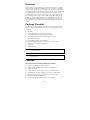
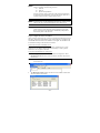
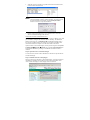
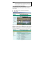
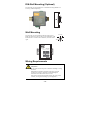
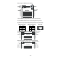
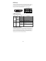
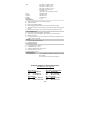
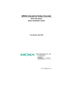
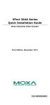
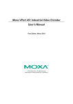
Moxa Video Encoder
VPort 251 Series
Quick Installation Guide
Second Edition, June 2008
© 2008 Moxa Inc., all rights reserved.
Reproduction without permission is prohibited.
P/N:1802002510010
Overview
The VPort 251 is a high performance, 1-channel video encoder in a compact
form factor that is suitable for installation in a variety of locations, including
outdoor camera cabinets. For easier installation, the VPort 251 supports both
panel mounting and DIN-rail mounting (with DK-35A accessory), and includes
a loop-through power output that can be used to power an analog camera.
In addition, the VPort 251 supports full-motion video at D1 resolution (720 ×
480 at 30 FPS for NTSC, 720 × 576 at 25 FPS for PAL). Both MPEG4 and
MJPEG are supported, making the VPort 251 especially suited for use with
distributed video surveillance systems. 2-way audio support is also built in,
allowing real-time voice communication between field engineers and control
centers.
Package Checklist
The VPort 251 is shipped with the following items. If any of these items are
missing or damaged, please contact your customer service representative for
assistance.
y
y
y
y
y
y
y
VPort 251
y
y
4 pcs pad
5-pin terminal block for 1 DI and 1 relay output
2-pin terminal block for loop-through power output
5-pin terminal block for RS-232/422/485 PTZ control port
Quick Installation Guide
Power adaptor (Need to order seperately)
Documentation & Software CD (includes User’s Manual, Quick
Installation Guide, datasheet, and utility)
Warranty booklet
NOTE Please verify that the model name printed on the unit's side label is
correct for your order.
NOTE This product must be installed in compliance with your local laws
and regulations.
Features
High Performance Video/Audio Networking Solution
y
y
y
y
y
y
y
y
Supports NTSC/PAL analog video cameras
Supports MPEG4/MJPEG video compression technology
1 BNC video input
1 audio input and 1 audio output for 2-way voice communication
Standard RTSP (real-time streaming protocol) for easy integration
Multicast (IGMP) protocols for efficient network transmission
QoS (TOS) for priority transmission
Full D1, 4CIF, VGA, QVGA, and CIF video resolutions
-2-
y
y
1 auto-sensing 10/100BaseT(X) Ethernet port
y
"Transparent PTZ Control" function to control remote PTZ cameras with
legacy PTZ control panel or keyboard
y
Built-in web server and RS-232 console for remote and local access &
configuration
y
y
y
y
y
TCP, UDP, and HTTP network transmission modes
RS-232/RS-422/RS-485 COM port for controlling PTZ (pan/tilt/zoom)
motorized cameras
Simultaneous access for up to 10 clients
Set video quality to CBR (constant bit rate) or VBR (variable bit rate)
Timestamp and text overlay
DDNS (Dynamic DNS), UPnP and IP filtering supported
Intelligent Alarm Trigger
y
y
Built-in video motion detection (VMD)
y
y
y
y
Alarm-triggered snapshots with pre-alarm and post-alarm snapshots
y
Configurable schedule for alarm activation
1 digital input channel and 1 relay (digital) output channel for external
sensor and alarm
Sequential snapshot images
Messages with snapshot images sent by FTP or email
HTTP action settings for customized alarm messages sent by HTTP event
server
Convenient Hardware Installation
y
Compact form factor for installation at almost any location
y
Panel mounting and DIN-rail mounting (with DK-35A accessory)
y
Loop-through power output with identical range as power input, for
powering analog cameras
Video Management and Control
y
Moxa SoftDVR™ Lite IP surveillance software included for viewing and
recording
y
Free VPort SDK PLUS available, with flexible interface and sample codes
for customized applications
NOTE If you are interested in the VPort SDK PLUS, please visit
moxa.com to download the software, or contact a Moxa sales
representative for more information.
-3-
VPort 251 Panel Layout
1. Grounding point
4
6
3
2. Power input jack (12 to 32
5
VDC or 18 to 30 VAC)
2
1
3. 5-pin terminal block for
digital input and relay output
4. Hardware reset button
5. 10/100BaseTX Ethernet
port with RJ45 connector,
LEDs
6. Status LEDs
7. Audio input jack
251
13
1-Channel Video Encoder
Video Input
Compression
MPEG4 or MJPEG
Ethernet
Auto 10/100 Mbps
Protocols
TCP,UDP,HTTP,DHCP,SMTP,
FTP,NTP,DNS,RTSP,IGMP,
QoS,DDNS,SNMP
GPIO
14
1-ch NTSC/PAL
RS-232 or RS-422/485
1x power input and
1x loop power output
(for speakers)
15 9. Vpp BNC connector for
D1x1,Relay Outputx1
PTZ
POWER
(mic in or line in)
8. Audio output jack
video input
10. 2-pin terminal block for
loop-through power output
11. RS-232 console port
12. 5-pin terminal block for
RS-232/422/485
13. Model name
12
11
8 14. Mounting point for wall
mounting
7
9 15. Mounting point for DK-35A
10
DIN-Rail Kit
NOTE The 2-pin terminal block for loop-through power output can be
used as an alternative power input port.
-4-
Initial Installation and Configuration
Before installing the VPort 251, verify that all items in the package checklist
are present. In addition, you will need a notebook or PC equipped with an
Ethernet port to complete the installation.
Step 1: Connect the power source, and connect loop-through power output
if required.
The VPort 251 can be powered by a 12 to 32 VDC power source, or an 18 to
30 VAC power source. The power input jack accepts a concentric barrel-type
connector. The loop-through power output accepts a 2-pin terminal block
connector. Check the STAT LED on the top panel to verify that power is
connected correctly.
NOTE The VPort 251's power output is looped through the power input
and will match the voltage of the power input source. For example,
if the power input is 12 VDC, the loop-through power output will
also be 12 VDC.
Step 2: Connect the VPort to the network.
The VPort 251 has an auto-sensing 10/100 Mbps Ethernet port, with built-in
LEDs to show 10 Mbps (amber) or 100 Mbps (green) connection activity.
Step 3: Connect the VPort to a camera and an audio source.
Use a coaxial cable to connect a video camera to the VPort's VIDEO INPUT
port, which uses a BNC connector.
A microphone or an amplifier can be plugged directly into the VPort's AUDIO
INPUT jack, and a speaker can be plugged into the AUDIO OUTPUT jack.
NOTE Check the VIDEO LED on the top panel to verify that the video
connection is working properly.
Step 4: Connect the VPort 251 to a motorized PTZ camera/device.
If you are using a PTZ camera or device, you can connect the PTZ control
cable to the VPort to allow PTZ control over the network. A 5-pin terminal
block for RS-232/422/485 serial connections is provided for this purpose. The
pin assignments are shown below:
PIN
1
2
3
4
5
RS-422/485
Ground
GND
RxRRx+
R+
Tx-/ DataT-\DTx+/ Data+
T+\D+
GND
--RxD
--TxD
RS-232
Ground
N/A
RxD
N/A
TxD
To enable PTZ control, configure the PTZ control protocol in the VPort's
web-based manager.
-5-
NOTE Drivers are required to support specific PTZ control protocols. The
VPort 251 supports the following protocols:
y
y
y
Pelco D
Pelco P
DynaColor DynaDome
For other protocols, please contact the video camera manufacturer
for the PTZ control commands. You may then use the VPort 251’s
Custom Camera function to program PTZ control.
NOTE New PTZ drivers can be uploaded for the VPort 251. Please contact
a Moxa sales rep to discuss development of new PTZ drivers.
NOTE The “Transparent PTZ Control” function can be used for PTZ
camera control over the network, without requiring special PTZ
drivers. PTZ cameras can be directly controlled by a keyboard or
PTZ control panel on the network.
Step 5: Configure the VPort’s IP address.
After powering on the VPort 251, wait a few seconds for the POST (Power On
Self Test). The STAT LED will turn green when the POST is completed. The
NETWORK LED will blink as the IP address is assigned. The IP address will
be selected according to the network environment.
Network Environment with DHCP Server
In this case, the VPort's IP address is assigned by a DHCP server. Use the
DHCP server’s IP address table or Moxa's VPort utility to look up the IP
address that was assigned to the VPort.
Using VPort and EtherDevice Configurator
1.
Run edscfgui.exe to start VPort and EtherDevice Configurator. Select
Broadcast Search from the List Server menu to search for the VPort on
the network.
NOTE VPort and Ether Device Configurator can be downloaded at
www.moxa.com.
2.
The Broadcast Search window will show a list of all EDS switches and
VPorts located on the network.
-6-
3.
When the search is complete, every EDS switch and VPort found on the
network will be listed onscreen.
NOTE Broadcast Search can only search for devices connected to the
same LAN domain as the PC running the utility. If your devices are
located on different LAN domain, use the Specify IP Address
function to search for a specific IP address.
4.
Double-click the selected VPort, or use a web browser to access the
VPort’s web-based manager (web console).
Network Environment without DHCP Server
If your VPort is connected to a network that does not have a DHCP server, then
you will need to configure the VPort's IP address manually. The default IP
address of the VPort 251 is 192.168.127.100 and the default subnet mask is
255.255.255.0. Make sure that you change your computer’s IP address and
subnet mask so that the computer is on the same subnet as the VPort.
Open the VPort’s web-based manager (see Step 6) and navigate to the System
Configuration Æ Network Æ General page. Select Use fixed IP address to
ensure that the IP address you assign is not deleted each time the VPort is
restarted.
Step 6: Open the VPort's web-based manager
In a web browser, enter the VPort's IP address as the URL to open the VPort's
web-based manager.
Step 7: Install the ActiveX Control plug-in
When you first access the VPort’s web-based manager, a message will appear
regarding the installation of the VPort ActiveX Control component. Click
"Yes" to allow the display of video images in the web browser.
-7-
NOTE For Windows XP SP2 or above, the ActiveX Control component
may be automatically blocked for security reasons. In this case, the
warning message may not appear. Unblock the ActiveX control
function or disable the security configuration to allow installation
of the VPort ActiveX Control component.
Step 8: Continue to the VPort’s web-based manager
After installing the ActiveX Control component, the VPort’s web-based
manager will appear. Check the following items to verify that the system was
installed properly:
y
y
y
Video images
Audio (make sure your PC’s or notebook’s sound is turned on)
Video information
Step 9: Access the VPort’s system configuration
In the VPort's web-based manager, the model name, server Name, IP address,
MAC address, firmware version, and LED status will be displayed at the top
of the page. Use this information to verify system information and installation.
Click System Configuration to see an overview of the system configuration.
-8-
For details on each item, please refer to the User’s Manual.
NOTE Administrators should go to System Configuration Æ System Æ
Account in the VPort’s web-based manager to set the
administrator’s password and enable authentication. The
administrator account name is admin. Each time the web-based
manager is opened, an authentication window will ask for the
account name and password.
Mounting Dimensions (unit=mm)
63.6
31.1
37.55
31.6
14.6
18
36.1
47.5
50
66.1
50
88.2
VPort 251
1-Channel Video Encoder
106
25
43
125.6
100.2
88.2
60.3
22.6
18.5
14.6
18.8
66.1
28.1
-9-
33.3
37.1
11
44.1
DIN-Rail Mounting (Optional)
The VPort 251 can be mounted on a 35-mm DIN-rail using the DK-35A
accessory (ordered separately).
Wall Mounting
The VPort 251 can be mounted on the wall with 2 screws.
Make sure that screws are less than 3.5 mm in diameter, with
heads between 3.5 and 6.0 mm in diameter, as shown on the
right.
6.0 mm
3.5 mm
VPort 251
1-Channel Video Encoder
Wiring Requirements
ATTENTION
Safety First!
Be sure to disconnect the power cord before installing or wiring
the VPort.
Determine the maximum current for each power wire and
common wire. Observe all electrical codes dictating the
maximum current allowed for each wire size.
If the current exceeds the maximum ratings, the wiring could
overheat, causing serious damage to your equipment.
- 10 -
You should also pay attention to the following:
y
y
y
y
Use separate paths to route wiring for power and devices. If power wiring
and device wiring paths must cross, make sure the wires are perpendicular
at the intersection point.
NOTE: Do not run signal or communications wiring and power wiring in
the same wire conduit. To avoid interference, wires with different signal
characteristics should be routed separately.
You can use the type of signal transmitted through a wire to determine
which wires should be kept separate. The rule of thumb is that wiring that
shares similar electrical characteristics can be bundled together.
Keep input wiring and output wiring separated.
It is strongly advised that you label wiring to all devices in the system when
necessary.
Grounding the VPort 251
Grounding and wire routing help limit the effects of noise from
electromagnetic interference (EMI). Before connecting devices, run the ground
connection from the grounding point on the VPort to the grounding surface.
ATTENTION
This product is intended to be mounted to a well-grounded
mounting surface such as a metal panel.
Wiring the Relay Output
The VPort 251 has one set of
relay outputs, labeled RELAY. 3
contacts on the 5-pin terminal
block on the VPort's top panel are
used for the relay output.
The relay output can be used for the following:
y System alarm, such as for network disconnection
y Event alarm, such as for VMD (video motion detection), video loss, or
digital inputs
The maximum current and power capacity of the relay output is 24
VDC @ 1A. Please be careful not to exceed this power
specification.
Before connecting the VPort to the DC/AC power inputs, make
sure that the DC power source voltage is stable.
Wiring the Digital Inputs
The VPort 251 has one digital input channel, labeled DI. Two contacts on the
5-pin terminal block on the VPort's top panel are used to connect to this DI.
- 11 -
STEP 1: Insert the negative
(ground)/positive DI wires into the
┴/I1 terminals.
STEP 2: To keep the DI wires from
pulling loose, use a small flathead
screwdriver to tighten the
connection.
STEP 3: Insert the terminal block
connector into the receptor on the
VPort’s top panel.
Communication Connections
The VPort 251 has an RS-232 console port and a 10/100BaseT(X) Ethernet
port, which both use RJ45 connectors.
RS-232 Connection
The RS-232 console port is on the top panel and uses a 10-pin RJ45 connector.
Use an RJ45-to-DB9 or RJ45-to-DB25 cable to connect your PC COM port to
the console port. Cable wiring diagrams are shown below. You may then use a
console terminal program, such as Moxa's PComm Terminal Emulator, to open
the VPort’s console configuration utility.
RJ45 (10-pin) Console Port Pin Assignment
Pin
1
2
3
4
5
6
7
8
9
10
Description
--DSR
--GND
TxD
RxD
GND
--DTR
---
1
10
RJ45 (10-pin) to DB9(F) Cable Wiring
RJ45 Plug Pin 1
1
DCD
2
DSR
3
RTS
GND 4/7
5
TxD
6
RxD
8
CTS
9
DTR
1
6
7
5
3
2
8
4
- 12 -
DCD
DTR
CTS
GND
RxD
TxD
RTS
DSR
RJ45 (10-pin) to DB25 (F) Cable Wiring
RJ45 Plug Pin 1
1
DCD
2
DSR
3
RTS
GND 4/7
5
TxD
6
RxD
8
CTS
9
DTR
8
6
4
7
2
3
5
20
DCD
DTR
CTS
GND
RxD
TxD
RTS
DSR
10/100BaseT(X) Ethernet Port Connection
The 10/100BaseT(X) port is on the VPort 251’s front panel and is used to
connect to Ethernet-enabled devices. The following table shows pinouts for
both MDI (NIC-type) ports and MDI-X (hub/switch-type) ports. Cable wiring
diagrams are also provided for straight-through and cross-over Ethernet cables.
(MDI) Port Pinouts
Pin
1
2
3
6
(MDI-X) Port Pinouts
Signal
Tx+
TxRx+
Rx-
Pin
1
2
3
6
8-pin RJ45
Signal
Rx+
RxTx+
Tx-
1
RJ45 (8-pin) to RJ45 (8-pin) Straight-Through Cable Wiring
Straight-Through Cable
Switch Port
RJ45 Plug Pin 1
RJ45
Connector
Tx+
TxRx+
Rx-
VPort Ethernet
Port
RJ45
Connector
Cable Wiring
3
6
1
2
3
6
1
2
Rx+
RxTx+
Tx-
RJ45 (8-pin) to RJ45 (8-pin) Cross-Over Cable Wiring
Cross-Over Cable
VPort Ethernet
Port
NIC Port
RJ45 Plug Pin 1
RJ45
Connector
(Rx+)
(Rx-)
(Tx+)
(Tx-)
Tx+
TxRx+
Rx-
RJ45
Connector
Cable Wiring
3
6
1
2
1
2
3
6
- 13 -
Rx+
RxTx+
Tx-
(Tx+)
(Tx-)
(Rx+)
(Rx-)
8
PTZ Port
A PTZ port is located on the VPort 251’s bottom panel. The port is used to
connect to a PTZ motorized camera or device, so that the camera or device can
be controlled from the VPort over the IP network. The PTZ port supports
RS-232 or RS-422/485 signals through the terminal block, with pin
assignments as shown in the following table:
Pin Assignment
PIN RS-422/485 RS-232
1
GND
GND
2
R--3
R+
RxD
4
T-/D--5
T+/D+
TxD
PTZ
5
4
3
2
1
LED Indicators
Several LED indicators are located on the front panel of the VPort 251:
LED
Color
RED
STAT
GREEN
VIDEO
PTZ
GREEN
State
Description
On
Hardware initialization
Flashing
Software initialization
On
System boot-up
Flashing
Firmware upgrade proceeding
On
Video signal is detected
Off
Video signal is not detected
On
RS-232 or RS-485 signals are being
transmitted
Off
RS-232 or RS-485 signals are not
being transmitted or have not been
detected
GREEN
Hardware Reset
The RESET button restores the system to the factory default settings. When the
system fails to install properly or operates abnormally, use a pointed object,
such as a straightened paper clip or toothpick, to hold the reset button down for
several seconds. When the STAT LED blinks red, release the button. The
POST process will run and the VPort will reboot. The STAT LED will glow a
steady green when the VPort has finished rebooting.
- 14 -
Specifications
Video
Video Compression
MPEG4, MJPEG
Video Input
1, BNC connector
NTSC/PAL
Auto-sensing or manual
Video Resolution and FPS (frames per second):
QVGA
CIF
VGA
4CIF
Full D1
Video Viewing
NTSC
PAL
Size
Max. FPS
Size
Max. FPS
320 × 240
30
320 × 288
25
352 × 240
30
352 × 288
25
640 × 480
30
640 × 576
25
704 × 480
30
704 × 576
25
720 × 480
30
720 × 576
25
y Adjustable image size and quality
y Timestamp and text overlay
Audio
Audio Input
Audio Output
Network
Protocols
Ethernet
Serial Port
PTZ Port
Console Port
GPIO
Digital Input
Relay Output
LED Indicators
STAT
VIDEO
PTZ
Power
Input
Output
Consumption
Mechanical
Housing
Dimension (W x D x H)
Weight
Installation
Environmental
Operating Temperature
Storage Temperature
Ambient Relative Humidity
Regulatory Approvals
EMI
1 line-in or mic-in jack, 3.5 mm
1 line-out jack, 3.5 mm
TCP, UDP, HTTP, SMTP, FTP, Telnet, NTP,
DNS, DHCP, UPnP, RTP, RTSP, ICMP,
IGMPv3, QoS (ToS), SNMP (V1/V2c/V3),
DDNS
1 auto-negotiating 10/100BaseT(X) port with
RJ45 connector
1 RS-232 or RS-422/485 port with terminal block
connector, max. speed of 115.2 Kbps
1 RS-232 port with RJ45 connector
1 channel, max. 8 mA
“Low”: +13V to +30V
“High”: -30V to +3V
1 channel, max. 24 VDC @ 1A
Indicates if the system booted properly
Video input signal active
PTZ control signal active
One 12/ 24 VDC or 24 VAC
2-pin terminal block for power output (looped
through power input)
Max. 7.5W
Metal case
88 x 107 x 50 mm (4.33 x 4.21 x 1.96 in)
850 g
Wall mounting or DIN-rail (with optional
DK-35A Kit)
0 to 60°C (32 to 140°F)
-40 to 85°C (-40 to 185°F)
5 to 95% (non-condensing)
FCC Part 15, CISPR (EN55022) class A
- 15 -
EMS
EN61000-4-2 (ESD), Level 2
EN61000-4-3 (RS), Level 3
EN61000-4-4 (EFT), Level 3
EN61000-4-5 (Surge), Level 3
EN61000-4-6 (CS), Level 3
EN61000-4-12
(Oscillatory wave immunity), Level 3
IEC60068-2-27
IEC60068-2-32
IEC60068-2-6
160,000 hours
5 years
Shock
Freefall
Vibration
MTBF
Warranty
Alarm Features
y Video motion detection with sensitivity tuning
y Video loss alarm
y Daily repeat timing schedule
y Alarm-triggered JPEG snapshots with pre and post-alarm images
y Automatic transfer of stored images by email or FTP, with event-triggered
actions
y HTTP action setting for custom alarm messages by HTTP event server
PTZ (Pan/Tilt/Zoom)
y PTZ camera control through RS-232/422/485
y Supports Dynacolor DynaDome, Pelco D, Pelco P, custom camera
y PTZ driver upload
y “Transparent PTZ Control” for network camera control using legacy PTZ
control panel or keyboard
Security
y User level password protection
y IP address filtering
System Requirements
y 2.4 GHz Pentium 4 or above
y 512 MB memory or above
y Windows XP/2000 with SP4 or above
y Internet Explorer 6 or above
y DirectX 9.0c or above
Bundled Software
Moxa SoftDVR Lite
1 to 4-channel IP surveillance software for viewing
& recording
(Visit moxa.com for release information.)
Technical Support Contact Information
www.moxa.com/support
Moxa Americas:
Toll-free: 1-888-669-2872
Tel:
+1-714-528-6777
Fax:
+1-714-528-6778
Moxa China (Shanghai office):
Toll-free: 800-820-5036
Tel:
+86-21-5258-9955
Fax:
+86-10-6872-3958
Moxa Europe:
Tel:
+49-89-3 70 03 99-0
Fax:
+49-89-3 70 03 99-99
Moxa Asia-Pacific:
Tel:
+886-2-8919-1230
Fax:
+886-2-8919-1231
- 16 -